

Getting Started
4535 612 62651 Rev A
September 2006
HD11 XE Ultrasound System
Copyright © 2006 Koninklijke Philips Electronics N.V. All rights reserved Printed in USA

Manufactured by Philips Ultrasound
22100 Bothell-Everett Highway
Bothell, WA 98021-8431
USA
Telephone: +1 425-487-7000 or 800-426-2670
Fax: +1 425-485-6080
www.medical.philips.com
This Medical Device meets the provisions of the transposition of the Medical
Device Directive 93/42/EEC within the country of origin of the Notified Body
concerned with the device.
European Union Representative
Philips Medical Systems Nederland B.V.
PMS Quality and Regulatory Affairs Europe
Veenpluis 4-6
5684 PC Best
The Netherlands
CAUTION
United States federal law restricts this device to sale by or on the order of a
physician.
This document and the information contained in it is proprietary and confidential information of Philips Medical Systems
("Philips") and may not be reproduced, copied in whole or in part, adapted, modified, disclosed to others, or disseminated
without the prior written permission of the Philips Legal Department. This document is intended to be used by customers
and is licensed to them as part of their Philips equipment purchase. Use of this document by unauthorized persons is strictly
prohibited.
Philips provides this document without warranty of any kind, implied or expres sed, inc luding, but not limited to, the implied
warranties of merchantability and fitness for a particular purpose.
HD11 XE Getting Started
2
4535 612 62651

Philips has taken care to ensure the accuracy of this document. However, Philips assumes no liability for errors or omissions
and reserves the right to make changes without further notice to any products herein to improve reliability, function, or
design. Philips may make improvements or changes in the products or programs described in this document at any time.
This product may contain remanufactured parts equivalent to new in performance, or parts that have had incidental use.
“Color Power Angio,” “HD11,” “High Q,” “OmniPlane,” “QLAB,” “SonoCT,” “Ultraband,” and “XRES” are trademarks of
Koninklijke Philips Electronics N.V.
Non-Philips product names may be trademarks of their respective owners.
HD11 XE Getting Started
4535 612 62651
3

4
HD11 XE Getting Started
4535 612 62651

Contents
1 Read This First . . . . . . . . . . . . . . . . . . . . . . . . . . . . . . . . . . . . . . . . . . . . . . . .15
Intended Audience . . . . . . . . . . . . . . . . . . . . . . . . . . . . . . . . . . . . . . . . . . . . . . . . . . . .15
Warnings. . . . . . . . . . . . . . . . . . . . . . . . . . . . . . . . . . . . . . . . . . . . . . . . . . . . . . . . . . . .15
Warning Symbols . . . . . . . . . . . . . . . . . . . . . . . . . . . . . . . . . . . . . . . . . . . . . . . . . . . . .16
About Your User Information . . . . . . . . . . . . . . . . . . . . . . . . . . . . . . . . . . . . . . . . . .16
About Your Compact Disc . . . . . . . . . . . . . . . . . . . . . . . . . . . . . . . . . . . . . . . . . . . . .17
Conventions . . . . . . . . . . . . . . . . . . . . . . . . . . . . . . . . . . . . . . . . . . . . . . . . . . . . . . . . .17
System Conventions. . . . . . . . . . . . . . . . . . . . . . . . . . . . . . . . . . . . . . . . . . . . . . . .17
User Information Conventions . . . . . . . . . . . . . . . . . . . . . . . . . . . . . . . . . . . . . . .18
Upgrades and Updates . . . . . . . . . . . . . . . . . . . . . . . . . . . . . . . . . . . . . . . . . . . . . . . . .19
Customer Comments . . . . . . . . . . . . . . . . . . . . . . . . . . . . . . . . . . . . . . . . . . . . . . . . .19
Ordering Supplies and Accessories . . . . . . . . . . . . . . . . . . . . . . . . . . . . . . . . . . . . . . .20
Customer Service. . . . . . . . . . . . . . . . . . . . . . . . . . . . . . . . . . . . . . . . . . . . . . . . . . . . .20
2 Safety. . . . . . . . . . . . . . . . . . . . . . . . . . . . . . . . . . . . . . . . . . . . . . . . . . . . . . . .23
Dangerous Voltages Symbol. . . . . . . . . . . . . . . . . . . . . . . . . . . . . . . . . . . . . . . . . . . . .23
Warnings. . . . . . . . . . . . . . . . . . . . . . . . . . . . . . . . . . . . . . . . . . . . . . . . . . . . . . . . . . . .23
Electrical Shock Hazard . . . . . . . . . . . . . . . . . . . . . . . . . . . . . . . . . . . . . . . . . . . . .23
Explosion Hazard . . . . . . . . . . . . . . . . . . . . . . . . . . . . . . . . . . . . . . . . . . . . . . . . . .24
Radio Frequency Communications Equipment Hazard. . . . . . . . . . . . . . . . . . . . .24
Electromagnetic Compatibility . . . . . . . . . . . . . . . . . . . . . . . . . . . . . . . . . . . . . . . . . . .24
ECG Signal . . . . . . . . . . . . . . . . . . . . . . . . . . . . . . . . . . . . . . . . . . . . . . . . . . . . . . . . . .26
Electrostatic Discharge Precautions . . . . . . . . . . . . . . . . . . . . . . . . . . . . . . . . . . . . . .26
Biological Safety . . . . . . . . . . . . . . . . . . . . . . . . . . . . . . . . . . . . . . . . . . . . . . . . . . . . . .27
ALARA Education Program . . . . . . . . . . . . . . . . . . . . . . . . . . . . . . . . . . . . . . . . . .28
Output Display . . . . . . . . . . . . . . . . . . . . . . . . . . . . . . . . . . . . . . . . . . . . . . . . . . . .33
Control Effects . . . . . . . . . . . . . . . . . . . . . . . . . . . . . . . . . . . . . . . . . . . . . . . . . . . .36
HD11 XE Getting Started
4535 612 62651
5

Contents
Related Guidance Documents . . . . . . . . . . . . . . . . . . . . . . . . . . . . . . . . . . . . . . .39
Acoustic Output and Measurement. . . . . . . . . . . . . . . . . . . . . . . . . . . . . . . . . . . .40
Acoustic Output Tables . . . . . . . . . . . . . . . . . . . . . . . . . . . . . . . . . . . . . . . . . . . . .43
Acoustic Measurement Precision and Uncertainty . . . . . . . . . . . . . . . . . . . . . . . .43
Symbols Used on the System . . . . . . . . . . . . . . . . . . . . . . . . . . . . . . . . . . . . . . . . . . . .45
Patient Safety . . . . . . . . . . . . . . . . . . . . . . . . . . . . . . . . . . . . . . . . . . . . . . . . . . . . . . . .47
Ultrasound Exposure . . . . . . . . . . . . . . . . . . . . . . . . . . . . . . . . . . . . . . . . . . . . . . .47
Thermal Exposure . . . . . . . . . . . . . . . . . . . . . . . . . . . . . . . . . . . . . . . . . . . . . . . . .48
Electrical Warnings. . . . . . . . . . . . . . . . . . . . . . . . . . . . . . . . . . . . . . . . . . . . . . . . .48
Installation Requirements. . . . . . . . . . . . . . . . . . . . . . . . . . . . . . . . . . . . . . . . . . . .49
AC Power Requirements . . . . . . . . . . . . . . . . . . . . . . . . . . . . . . . . . . . . . . . . . . . .50
Defibrillators. . . . . . . . . . . . . . . . . . . . . . . . . . . . . . . . . . . . . . . . . . . . . . . . . . . . . .51
Pacemakers . . . . . . . . . . . . . . . . . . . . . . . . . . . . . . . . . . . . . . . . . . . . . . . . . . . . . . .51
Explosive Hazards. . . . . . . . . . . . . . . . . . . . . . . . . . . . . . . . . . . . . . . . . . . . . . . . . .52
Philips Transducers. . . . . . . . . . . . . . . . . . . . . . . . . . . . . . . . . . . . . . . . . . . . . . . . .52
Latex Materials and Patient Contact . . . . . . . . . . . . . . . . . . . . . . . . . . . . . . . . . . .52
FDA Medical Alert . . . . . . . . . . . . . . . . . . . . . . . . . . . . . . . . . . . . . . . . . . . . . . . . .52
Transmissible Spongiform Encephalopathy . . . . . . . . . . . . . . . . . . . . . . . . . . . . . .54
Peripherals Connections . . . . . . . . . . . . . . . . . . . . . . . . . . . . . . . . . . . . . . . . . . . .55
Operator Safety . . . . . . . . . . . . . . . . . . . . . . . . . . . . . . . . . . . . . . . . . . . . . . . . . . . . . .56
Repetitive Strain Injury . . . . . . . . . . . . . . . . . . . . . . . . . . . . . . . . . . . . . . . . . . . . .56
Foot Switch Warning . . . . . . . . . . . . . . . . . . . . . . . . . . . . . . . . . . . . . . . . . . . . . . .57
Philips Transducers. . . . . . . . . . . . . . . . . . . . . . . . . . . . . . . . . . . . . . . . . . . . . . . . .57
Electrical Warnings. . . . . . . . . . . . . . . . . . . . . . . . . . . . . . . . . . . . . . . . . . . . . . . . .57
Explosive Hazards. . . . . . . . . . . . . . . . . . . . . . . . . . . . . . . . . . . . . . . . . . . . . . . . . .57
Glutaraldehyde Exposure . . . . . . . . . . . . . . . . . . . . . . . . . . . . . . . . . . . . . . . . . . . .57
Infection Control . . . . . . . . . . . . . . . . . . . . . . . . . . . . . . . . . . . . . . . . . . . . . . . . . .58
3 System Overview . . . . . . . . . . . . . . . . . . . . . . . . . . . . . . . . . . . . . . . . . . . . . 61
About the HD11 XE Ultrasound System. . . . . . . . . . . . . . . . . . . . . . . . . . . . . . . . . . .61
HD11 XE Getting Started
6
4535 612 62651

Contents
Intended Uses. . . . . . . . . . . . . . . . . . . . . . . . . . . . . . . . . . . . . . . . . . . . . . . . . . . . . . . .62
Studies. . . . . . . . . . . . . . . . . . . . . . . . . . . . . . . . . . . . . . . . . . . . . . . . . . . . . . . . . . . . . .63
Abdominal Studies . . . . . . . . . . . . . . . . . . . . . . . . . . . . . . . . . . . . . . . . . . . . . . . . .63
Cardiac Studies. . . . . . . . . . . . . . . . . . . . . . . . . . . . . . . . . . . . . . . . . . . . . . . . . . . .64
Gynecological Studies. . . . . . . . . . . . . . . . . . . . . . . . . . . . . . . . . . . . . . . . . . . . . . .64
Intraoperative Studies . . . . . . . . . . . . . . . . . . . . . . . . . . . . . . . . . . . . . . . . . . . . . .65
Neonatal Head Studies. . . . . . . . . . . . . . . . . . . . . . . . . . . . . . . . . . . . . . . . . . . . . .66
Obstetrical Studies . . . . . . . . . . . . . . . . . . . . . . . . . . . . . . . . . . . . . . . . . . . . . . . . .66
Pediatric Studies . . . . . . . . . . . . . . . . . . . . . . . . . . . . . . . . . . . . . . . . . . . . . . . . . . .67
Small Parts Studies . . . . . . . . . . . . . . . . . . . . . . . . . . . . . . . . . . . . . . . . . . . . . . . . .67
Transcranial Studies . . . . . . . . . . . . . . . . . . . . . . . . . . . . . . . . . . . . . . . . . . . . . . . .68
Vascular Studies . . . . . . . . . . . . . . . . . . . . . . . . . . . . . . . . . . . . . . . . . . . . . . . . . . .68
Ultrasound System Components . . . . . . . . . . . . . . . . . . . . . . . . . . . . . . . . . . . . . . . . .69
System Control Panel Components . . . . . . . . . . . . . . . . . . . . . . . . . . . . . . . . . . .71
Display . . . . . . . . . . . . . . . . . . . . . . . . . . . . . . . . . . . . . . . . . . . . . . . . . . . . . . . . . .72
About Standard Features, Clinical Options, and Purchasable Options. . . . . . . . . . . .73
Standard Features. . . . . . . . . . . . . . . . . . . . . . . . . . . . . . . . . . . . . . . . . . . . . . . . . .73
Clinical Options . . . . . . . . . . . . . . . . . . . . . . . . . . . . . . . . . . . . . . . . . . . . . . . . . . .73
Purchasable Options. . . . . . . . . . . . . . . . . . . . . . . . . . . . . . . . . . . . . . . . . . . . . . . .75
4 Using the System . . . . . . . . . . . . . . . . . . . . . . . . . . . . . . . . . . . . . . . . . . . . . .79
Turning the System On and Off. . . . . . . . . . . . . . . . . . . . . . . . . . . . . . . . . . . . . . . . . .79
Positioning the Control Panel and Monitor. . . . . . . . . . . . . . . . . . . . . . . . . . . . . . . . .80
Adjusting the Monitor Position . . . . . . . . . . . . . . . . . . . . . . . . . . . . . . . . . . . . . . .80
Locking and Unlocking the Monitor Arm . . . . . . . . . . . . . . . . . . . . . . . . . . . . . . .81
Adjusting the Monitor Display . . . . . . . . . . . . . . . . . . . . . . . . . . . . . . . . . . . . . . . .81
Raising, Lowering, and Swiveling the System Control Panel . . . . . . . . . . . . . . . . .82
Using the System Control Panel . . . . . . . . . . . . . . . . . . . . . . . . . . . . . . . . . . . . . . . . .82
Soft Keys. . . . . . . . . . . . . . . . . . . . . . . . . . . . . . . . . . . . . . . . . . . . . . . . . . . . . . . . .82
Keyboard . . . . . . . . . . . . . . . . . . . . . . . . . . . . . . . . . . . . . . . . . . . . . . . . . . . . . . . .83
HD11 XE Getting Started
4535 612 62651
7

Contents
Select and Enter Keys and the Trackball . . . . . . . . . . . . . . . . . . . . . . . . . . . . . . . .83
Changing the Current Input Language . . . . . . . . . . . . . . . . . . . . . . . . . . . . . . . . . . . . .84
Customizing Your System . . . . . . . . . . . . . . . . . . . . . . . . . . . . . . . . . . . . . . . . . . . . . .84
About Presets . . . . . . . . . . . . . . . . . . . . . . . . . . . . . . . . . . . . . . . . . . . . . . . . . . . . .84
Changing and Saving System Settings . . . . . . . . . . . . . . . . . . . . . . . . . . . . . . . . . . .85
Installing, Removing, and Disabling Options . . . . . . . . . . . . . . . . . . . . . . . . . . . . .85
Assigning Option Keys . . . . . . . . . . . . . . . . . . . . . . . . . . . . . . . . . . . . . . . . . . . . . .86
Making Backups. . . . . . . . . . . . . . . . . . . . . . . . . . . . . . . . . . . . . . . . . . . . . . . . . . . . . . .86
Backing Up Presets . . . . . . . . . . . . . . . . . . . . . . . . . . . . . . . . . . . . . . . . . . . . . . . . .86
Backing Up System Settings . . . . . . . . . . . . . . . . . . . . . . . . . . . . . . . . . . . . . . . . . .87
Backing Up Patient Folders . . . . . . . . . . . . . . . . . . . . . . . . . . . . . . . . . . . . . . . . . .87
Managing Patient Data . . . . . . . . . . . . . . . . . . . . . . . . . . . . . . . . . . . . . . . . . . . . . . . . .88
Managing Data Security . . . . . . . . . . . . . . . . . . . . . . . . . . . . . . . . . . . . . . . . . . . . . . . .89
Configuring Network Settings . . . . . . . . . . . . . . . . . . . . . . . . . . . . . . . . . . . . . . . . . . .90
Configuring the System’s Network Settings . . . . . . . . . . . . . . . . . . . . . . . . . . . . .90
Adding a DICOM Server . . . . . . . . . . . . . . . . . . . . . . . . . . . . . . . . . . . . . . . . . . . .91
Associating DICOM Servers with Roles . . . . . . . . . . . . . . . . . . . . . . . . . . . . . . . .92
Checking the DICOM Job Manager . . . . . . . . . . . . . . . . . . . . . . . . . . . . . . . . . . . .93
Connecting Peripherals . . . . . . . . . . . . . . . . . . . . . . . . . . . . . . . . . . . . . . . . . . . . . . . .94
Connecting a Printer . . . . . . . . . . . . . . . . . . . . . . . . . . . . . . . . . . . . . . . . . . . . . . .97
Connecting a VCR . . . . . . . . . . . . . . . . . . . . . . . . . . . . . . . . . . . . . . . . . . . . . . . .102
Assigning Keys to Peripherals . . . . . . . . . . . . . . . . . . . . . . . . . . . . . . . . . . . . . . .103
Connecting and Configuring the Foot Switch . . . . . . . . . . . . . . . . . . . . . . . . . . .103
Configuring and Using the Data Transfer Feature. . . . . . . . . . . . . . . . . . . . . . . . . . .105
Assigning a Record Key . . . . . . . . . . . . . . . . . . . . . . . . . . . . . . . . . . . . . . . . . . . .105
Transferring Data . . . . . . . . . . . . . . . . . . . . . . . . . . . . . . . . . . . . . . . . . . . . . . . . .106
Moving and Transporting the System . . . . . . . . . . . . . . . . . . . . . . . . . . . . . . . . . . . .106
Taking Precautions When Moving the System . . . . . . . . . . . . . . . . . . . . . . . . . .107
Using the Wheel Controls . . . . . . . . . . . . . . . . . . . . . . . . . . . . . . . . . . . . . . . . . .108
HD11 XE Getting Started
8
4535 612 62651

Contents
Moving the System . . . . . . . . . . . . . . . . . . . . . . . . . . . . . . . . . . . . . . . . . . . . . . . .109
Transporting the System in a Vehicle . . . . . . . . . . . . . . . . . . . . . . . . . . . . . . . . .109
Getting Help and Troubleshooting Your System . . . . . . . . . . . . . . . . . . . . . . . . . . .111
Using the Help . . . . . . . . . . . . . . . . . . . . . . . . . . . . . . . . . . . . . . . . . . . . . . . . . . .111
Getting Technical Support . . . . . . . . . . . . . . . . . . . . . . . . . . . . . . . . . . . . . . . . . .111
Troubleshooting . . . . . . . . . . . . . . . . . . . . . . . . . . . . . . . . . . . . . . . . . . . . . . . . . .113
5Cleaning and Maintaining the System . . . . . . . . . . . . . . . . . . . . . . . . . . . .115
Cleaning and Disinfecting System Surfaces . . . . . . . . . . . . . . . . . . . . . . . . . . . . . . . .115
Cleaning the Cables and the Connectors . . . . . . . . . . . . . . . . . . . . . . . . . . . . . . . . .117
Preventive Maintenance . . . . . . . . . . . . . . . . . . . . . . . . . . . . . . . . . . . . . . . . . . . . . . .118
Recommended Frequency of Maintenance Procedures . . . . . . . . . . . . . . . . . . .118
Service Documentation . . . . . . . . . . . . . . . . . . . . . . . . . . . . . . . . . . . . . . . . . . . . . . .119
Electrostatic Discharge Guidelines . . . . . . . . . . . . . . . . . . . . . . . . . . . . . . . . . . . . . .120
Maintaining the System Control Panel . . . . . . . . . . . . . . . . . . . . . . . . . . . . . . . . . . .121
Cleaning the Air Filter . . . . . . . . . . . . . . . . . . . . . . . . . . . . . . . . . . . . . . . . . . . . .121
Cleaning the Trackball . . . . . . . . . . . . . . . . . . . . . . . . . . . . . . . . . . . . . . . . . . . . .122
Cleaning and Maintaining Peripherals. . . . . . . . . . . . . . . . . . . . . . . . . . . . . . . . . . . . .123
VCR. . . . . . . . . . . . . . . . . . . . . . . . . . . . . . . . . . . . . . . . . . . . . . . . . . . . . . . . . . . .123
Video Printers. . . . . . . . . . . . . . . . . . . . . . . . . . . . . . . . . . . . . . . . . . . . . . . . . . . .123
Replacing the System Battery. . . . . . . . . . . . . . . . . . . . . . . . . . . . . . . . . . . . . . . . . . .124
Disposing of Equipment . . . . . . . . . . . . . . . . . . . . . . . . . . . . . . . . . . . . . . . . . . . . . . .124
6Device Standards. . . . . . . . . . . . . . . . . . . . . . . . . . . . . . . . . . . . . . . . . . . . .125
Specifications. . . . . . . . . . . . . . . . . . . . . . . . . . . . . . . . . . . . . . . . . . . . . . . . . . . . . . . .125
Model Number . . . . . . . . . . . . . . . . . . . . . . . . . . . . . . . . . . . . . . . . . . . . . . . . . . .125
Power Requirements . . . . . . . . . . . . . . . . . . . . . . . . . . . . . . . . . . . . . . . . . . . . . .125
Operating Environment . . . . . . . . . . . . . . . . . . . . . . . . . . . . . . . . . . . . . . . . . . . .125
Storage Environment . . . . . . . . . . . . . . . . . . . . . . . . . . . . . . . . . . . . . . . . . . . . . .125
Regulatory Compliance . . . . . . . . . . . . . . . . . . . . . . . . . . . . . . . . . . . . . . . . . . . . . . .125
HD11 XE Getting Started
4535 612 62651
9

Contents
Standards and Directives . . . . . . . . . . . . . . . . . . . . . . . . . . . . . . . . . . . . . . . . . . . . . .126
Audible Acoustic Output . . . . . . . . . . . . . . . . . . . . . . . . . . . . . . . . . . . . . . . . . . . . . .127
Electromagnetic Compatibility . . . . . . . . . . . . . . . . . . . . . . . . . . . . . . . . . . . . . . . . . .127
Electromagnetic Emissions . . . . . . . . . . . . . . . . . . . . . . . . . . . . . . . . . . . . . . . . . .128
Approved Cables, Transducers, and Accessories for EMC . . . . . . . . . . . . . . . .128
Electromagnetic Immunity . . . . . . . . . . . . . . . . . . . . . . . . . . . . . . . . . . . . . . . . . .131
Recommended Separation Distance . . . . . . . . . . . . . . . . . . . . . . . . . . . . . . . . . .135
Avoiding Electromagnetic Interference . . . . . . . . . . . . . . . . . . . . . . . . . . . . . . . .137
Restrictions for Use . . . . . . . . . . . . . . . . . . . . . . . . . . . . . . . . . . . . . . . . . . . . . . .138
Immunity Level Test Results . . . . . . . . . . . . . . . . . . . . . . . . . . . . . . . . . . . . . . . .138
Electrosurgical Units. . . . . . . . . . . . . . . . . . . . . . . . . . . . . . . . . . . . . . . . . . . . . . . . . .139
Input/Output Connections. . . . . . . . . . . . . . . . . . . . . . . . . . . . . . . . . . . . . . . . . . . . .139
System Input/Output Connections . . . . . . . . . . . . . . . . . . . . . . . . . . . . . . . . . . .139
ECG/Physio Input Connections . . . . . . . . . . . . . . . . . . . . . . . . . . . . . . . . . . . . . .142
7 Transducers. . . . . . . . . . . . . . . . . . . . . . . . . . . . . . . . . . . . . . . . . . . . . . . . . 145
Supported Transducers . . . . . . . . . . . . . . . . . . . . . . . . . . . . . . . . . . . . . . . . . . . . . . .145
Specialty Transducers. . . . . . . . . . . . . . . . . . . . . . . . . . . . . . . . . . . . . . . . . . . . . .149
Connecting Transducers . . . . . . . . . . . . . . . . . . . . . . . . . . . . . . . . . . . . . . . . . . . . . .150
Activating Transducers. . . . . . . . . . . . . . . . . . . . . . . . . . . . . . . . . . . . . . . . . . . . . . . .154
Transducer Supplies and Accessories . . . . . . . . . . . . . . . . . . . . . . . . . . . . . . . . . . . .154
8 Transducer Care and Maintenance . . . . . . . . . . . . . . . . . . . . . . . . . . . . . . 155
Handling Transducers. . . . . . . . . . . . . . . . . . . . . . . . . . . . . . . . . . . . . . . . . . . . . . . . .155
Inspecting Transducers for Damage. . . . . . . . . . . . . . . . . . . . . . . . . . . . . . . . . . . . . .156
Installing and Cleaning the Ergonomic Grip. . . . . . . . . . . . . . . . . . . . . . . . . . . . . . . .156
Storing Transducers . . . . . . . . . . . . . . . . . . . . . . . . . . . . . . . . . . . . . . . . . . . . . . . . . .157
Storage for Transport . . . . . . . . . . . . . . . . . . . . . . . . . . . . . . . . . . . . . . . . . . . . .157
Daily and Long-Term Storage . . . . . . . . . . . . . . . . . . . . . . . . . . . . . . . . . . . . . . .158
Safety Considerations When Using Disinfectants and Gels . . . . . . . . . . . . . . . . . . .159
HD11 XE Getting Started
10
4535 612 62651

Contents
Latex Product Alert . . . . . . . . . . . . . . . . . . . . . . . . . . . . . . . . . . . . . . . . . . . . . . .160
Transmissible Spongiform Encephalopathy . . . . . . . . . . . . . . . . . . . . . . . . . . . . . . . .160
Acoustic Coupling Medium . . . . . . . . . . . . . . . . . . . . . . . . . . . . . . . . . . . . . . . . . . . .161
Cleaning, Disinfecting, and Sterilizing Transducers . . . . . . . . . . . . . . . . . . . . . . . . . .161
Choosing a Disinfectant . . . . . . . . . . . . . . . . . . . . . . . . . . . . . . . . . . . . . . . . . . . .161
General Cleaning Procedures for All Transducers . . . . . . . . . . . . . . . . . . . . . . .162
Disinfecting Transducers with Wipes and Sprays
(Low to Intermediate-Level Disinfection) . . . . . . . . . . . . . . . . . . . . . . . . . . . . . .163
Cleaning and Disinfecting Cables and Connectors with Wipes and Sprays . . . .164
Disinfecting Transducers by Immersion (High-Level Disinfection). . . . . . . . . . .167
Sterilizing Transducers . . . . . . . . . . . . . . . . . . . . . . . . . . . . . . . . . . . . . . . . . . . . .173
Disinfectants Compatibility . . . . . . . . . . . . . . . . . . . . . . . . . . . . . . . . . . . . . . . . . . . .176
Disinfectant Types . . . . . . . . . . . . . . . . . . . . . . . . . . . . . . . . . . . . . . . . . . . . . . . .177
Factors Affecting Disinfectant Efficiency . . . . . . . . . . . . . . . . . . . . . . . . . . . . . . .177
Disinfectants Compatibility Table . . . . . . . . . . . . . . . . . . . . . . . . . . . . . . . . . . . . . . .178
Gels Statement . . . . . . . . . . . . . . . . . . . . . . . . . . . . . . . . . . . . . . . . . . . . . . . . . . . . . .192
9 Endocavity Transducers . . . . . . . . . . . . . . . . . . . . . . . . . . . . . . . . . . . . . . .193
Operator. . . . . . . . . . . . . . . . . . . . . . . . . . . . . . . . . . . . . . . . . . . . . . . . . . . . . . . . . . .193
Patient Safety . . . . . . . . . . . . . . . . . . . . . . . . . . . . . . . . . . . . . . . . . . . . . . . . . . . . . . .193
Equipment Operation. . . . . . . . . . . . . . . . . . . . . . . . . . . . . . . . . . . . . . . . . . . . . . . . .195
Electrical Safety. . . . . . . . . . . . . . . . . . . . . . . . . . . . . . . . . . . . . . . . . . . . . . . . . . . . . .195
Description and Use. . . . . . . . . . . . . . . . . . . . . . . . . . . . . . . . . . . . . . . . . . . . . . . . . .195
C8-4v Endocavity Transducer . . . . . . . . . . . . . . . . . . . . . . . . . . . . . . . . . . . . . . .196
3D9-3v Endocavity Transducer . . . . . . . . . . . . . . . . . . . . . . . . . . . . . . . . . . . . . .197
C9-5ec Endocavity Transducer . . . . . . . . . . . . . . . . . . . . . . . . . . . . . . . . . . . . . .198
The Endocavity Exam . . . . . . . . . . . . . . . . . . . . . . . . . . . . . . . . . . . . . . . . . . . . . . . . .199
Preparing the Endocavity Transducer for an Exam . . . . . . . . . . . . . . . . . . . . . . .199
Preparing a Patient for an Endocavity Exam . . . . . . . . . . . . . . . . . . . . . . . . . . . .201
Endocavity Examination Guidelines . . . . . . . . . . . . . . . . . . . . . . . . . . . . . . . . . . .201
HD11 XE Getting Started
4535 612 62651
11

Contents
Accessories for Endocavity Transducers . . . . . . . . . . . . . . . . . . . . . . . . . . . . . . . . . .202
10 TEE Transducers. . . . . . . . . . . . . . . . . . . . . . . . . . . . . . . . . . . . . . . . . . . . . 203
Operator. . . . . . . . . . . . . . . . . . . . . . . . . . . . . . . . . . . . . . . . . . . . . . . . . . . . . . . . . . .203
Patient Safety . . . . . . . . . . . . . . . . . . . . . . . . . . . . . . . . . . . . . . . . . . . . . . . . . . . . . . .204
Equipment Operation. . . . . . . . . . . . . . . . . . . . . . . . . . . . . . . . . . . . . . . . . . . . . . . . .207
Electrical Safety. . . . . . . . . . . . . . . . . . . . . . . . . . . . . . . . . . . . . . . . . . . . . . . . . . . . . .208
Leakage Current . . . . . . . . . . . . . . . . . . . . . . . . . . . . . . . . . . . . . . . . . . . . . . . . . .209
Electrosurgical Units. . . . . . . . . . . . . . . . . . . . . . . . . . . . . . . . . . . . . . . . . . . . . . .209
Pacemakers . . . . . . . . . . . . . . . . . . . . . . . . . . . . . . . . . . . . . . . . . . . . . . . . . . . . . .209
Defibrillators. . . . . . . . . . . . . . . . . . . . . . . . . . . . . . . . . . . . . . . . . . . . . . . . . . . . .210
Accident Prevention . . . . . . . . . . . . . . . . . . . . . . . . . . . . . . . . . . . . . . . . . . . . . . .210
OmniPlane III Transducers . . . . . . . . . . . . . . . . . . . . . . . . . . . . . . . . . . . . . . . . . . . . .210
Basic Transducer Parts . . . . . . . . . . . . . . . . . . . . . . . . . . . . . . . . . . . . . . . . . . . . .211
Deflection Control Basics . . . . . . . . . . . . . . . . . . . . . . . . . . . . . . . . . . . . . . . . . .212
Temperature Controls . . . . . . . . . . . . . . . . . . . . . . . . . . . . . . . . . . . . . . . . . . . . .213
Description and Use: OmniPlane III Transducer . . . . . . . . . . . . . . . . . . . . . . . . . . . .214
Manipulating the OmniPlane III Tip . . . . . . . . . . . . . . . . . . . . . . . . . . . . . . . . . . .215
Rotating the OmniPlane Array. . . . . . . . . . . . . . . . . . . . . . . . . . . . . . . . . . . . . . .216
Calibration . . . . . . . . . . . . . . . . . . . . . . . . . . . . . . . . . . . . . . . . . . . . . . . . . . . . . .217
Checking the TEE Transducer . . . . . . . . . . . . . . . . . . . . . . . . . . . . . . . . . . . . . . . . . .218
Inspecting the Transducer . . . . . . . . . . . . . . . . . . . . . . . . . . . . . . . . . . . . . . . . . .218
Verifying Operation of the Controls . . . . . . . . . . . . . . . . . . . . . . . . . . . . . . . . . .219
S7-3t TEE Transducer . . . . . . . . . . . . . . . . . . . . . . . . . . . . . . . . . . . . . . . . . . . . .219
Selecting Patients for the S7-3t Transducer . . . . . . . . . . . . . . . . . . . . . . . . . . . .221
Deflection and Scan Plane Rotation Control. . . . . . . . . . . . . . . . . . . . . . . . . . . .221
Tip Deflection Control. . . . . . . . . . . . . . . . . . . . . . . . . . . . . . . . . . . . . . . . . . . . .221
Lock Operation . . . . . . . . . . . . . . . . . . . . . . . . . . . . . . . . . . . . . . . . . . . . . . . . . .222
Transducer Scan Plane Rotation Control . . . . . . . . . . . . . . . . . . . . . . . . . . . . . .222
Special Considerations for TEE Examinations . . . . . . . . . . . . . . . . . . . . . . . . . . . . . .224
HD11 XE Getting Started
12
4535 612 62651

Contents
Preparing Patients for a TEE Examination . . . . . . . . . . . . . . . . . . . . . . . . . . . . . . . . .224
Examination Guidelines . . . . . . . . . . . . . . . . . . . . . . . . . . . . . . . . . . . . . . . . . . . .225
Tip Fold-Over. . . . . . . . . . . . . . . . . . . . . . . . . . . . . . . . . . . . . . . . . . . . . . . . . . . .227
Recognizing Tip Fold-Over. . . . . . . . . . . . . . . . . . . . . . . . . . . . . . . . . . . . . . . . . .228
Correcting Tip Fold-Over . . . . . . . . . . . . . . . . . . . . . . . . . . . . . . . . . . . . . . . . . .228
Ensuring Accurate Temperature Sensing. . . . . . . . . . . . . . . . . . . . . . . . . . . . . . . . . .228
TEE Manual Auto-Cool Safety Feature . . . . . . . . . . . . . . . . . . . . . . . . . . . . . . . .229
Entering the Patient Temperature . . . . . . . . . . . . . . . . . . . . . . . . . . . . . . . . . . . .230
Monitoring the Distal Tip Temperature . . . . . . . . . . . . . . . . . . . . . . . . . . . . . . .231
Resuming Imaging After an Auto-Cool Interruption. . . . . . . . . . . . . . . . . . . . . .233
Changing Temperature Display Options . . . . . . . . . . . . . . . . . . . . . . . . . . . . . . .234
Checking the Patient After a TEE Examination . . . . . . . . . . . . . . . . . . . . . . . . . . . . .234
TEE Accessories . . . . . . . . . . . . . . . . . . . . . . . . . . . . . . . . . . . . . . . . . . . . . . . . . . . . .235
Bite Guards. . . . . . . . . . . . . . . . . . . . . . . . . . . . . . . . . . . . . . . . . . . . . . . . . . . . . .235
Tip Protector . . . . . . . . . . . . . . . . . . . . . . . . . . . . . . . . . . . . . . . . . . . . . . . . . . . .235
Transducer Covers. . . . . . . . . . . . . . . . . . . . . . . . . . . . . . . . . . . . . . . . . . . . . . . .236
Disposable Drape . . . . . . . . . . . . . . . . . . . . . . . . . . . . . . . . . . . . . . . . . . . . . . . . .236
Electrical Safety Check Procedure for TEE Transducers . . . . . . . . . . . . . . . . . . . . .236
Test Background. . . . . . . . . . . . . . . . . . . . . . . . . . . . . . . . . . . . . . . . . . . . . . . . . .236
Equipment and Procedure . . . . . . . . . . . . . . . . . . . . . . . . . . . . . . . . . . . . . . . . . .238
11 Biopsy-Capable Transducers. . . . . . . . . . . . . . . . . . . . . . . . . . . . . . . . . . . .241
Transducers Supporting Biopsy . . . . . . . . . . . . . . . . . . . . . . . . . . . . . . . . . . . . . . . . .241
Biopsy Guide Instructions . . . . . . . . . . . . . . . . . . . . . . . . . . . . . . . . . . . . . . . . . . . . .242
Using the Biopsy Needle Guide . . . . . . . . . . . . . . . . . . . . . . . . . . . . . . . . . . . . . . . . .243
Biopsy Precautions . . . . . . . . . . . . . . . . . . . . . . . . . . . . . . . . . . . . . . . . . . . . . . . . . . .243
12 Intraoperative Transducers . . . . . . . . . . . . . . . . . . . . . . . . . . . . . . . . . . . .245
Operator. . . . . . . . . . . . . . . . . . . . . . . . . . . . . . . . . . . . . . . . . . . . . . . . . . . . . . . . . . .245
Intended Use. . . . . . . . . . . . . . . . . . . . . . . . . . . . . . . . . . . . . . . . . . . . . . . . . . . . . . . .246
HD11 XE Getting Started
4535 612 62651
13

Contents
Patient Safety . . . . . . . . . . . . . . . . . . . . . . . . . . . . . . . . . . . . . . . . . . . . . . . . . . . . . . .246
Patient Contact Parts . . . . . . . . . . . . . . . . . . . . . . . . . . . . . . . . . . . . . . . . . . . . . .247
Equipment Operation. . . . . . . . . . . . . . . . . . . . . . . . . . . . . . . . . . . . . . . . . . . . . .247
Description and Use. . . . . . . . . . . . . . . . . . . . . . . . . . . . . . . . . . . . . . . . . . . . . . . . . .249
Preparing a Transducer for Intraoperative Imaging. . . . . . . . . . . . . . . . . . . . . . . . . .250
Disposable Drape . . . . . . . . . . . . . . . . . . . . . . . . . . . . . . . . . . . . . . . . . . . . . . . . .252
Accessory Equipment . . . . . . . . . . . . . . . . . . . . . . . . . . . . . . . . . . . . . . . . . . . . . .252
Electrical Safety. . . . . . . . . . . . . . . . . . . . . . . . . . . . . . . . . . . . . . . . . . . . . . . . . . .252
Defibrillators. . . . . . . . . . . . . . . . . . . . . . . . . . . . . . . . . . . . . . . . . . . . . . . . . . . . .252
Accessory Equipment . . . . . . . . . . . . . . . . . . . . . . . . . . . . . . . . . . . . . . . . . . . . . . . . .252
Testing Leakage Current on Intraoperative Transducers . . . . . . . . . . . . . . . . . . . . .253
Leakage Current . . . . . . . . . . . . . . . . . . . . . . . . . . . . . . . . . . . . . . . . . . . . . . . . . .253
Leakage Current Testing . . . . . . . . . . . . . . . . . . . . . . . . . . . . . . . . . . . . . . . . . . .253
Appendix A HD11 XE System Supplies, Peripherals, and Accessories. . . . 259
Ordering Parts . . . . . . . . . . . . . . . . . . . . . . . . . . . . . . . . . . . . . . . . . . . . . . . . . . . . . .259
Supplies . . . . . . . . . . . . . . . . . . . . . . . . . . . . . . . . . . . . . . . . . . . . . . . . . . . . . . . . . . . .259
Physio Supplies . . . . . . . . . . . . . . . . . . . . . . . . . . . . . . . . . . . . . . . . . . . . . . . . . . .259
Printer Supplies. . . . . . . . . . . . . . . . . . . . . . . . . . . . . . . . . . . . . . . . . . . . . . . . . . .261
VCR Supplies . . . . . . . . . . . . . . . . . . . . . . . . . . . . . . . . . . . . . . . . . . . . . . . . . . . .262
Removable Media . . . . . . . . . . . . . . . . . . . . . . . . . . . . . . . . . . . . . . . . . . . . . . . . .262
Transducer Supplies . . . . . . . . . . . . . . . . . . . . . . . . . . . . . . . . . . . . . . . . . . . . . . .263
Peripherals . . . . . . . . . . . . . . . . . . . . . . . . . . . . . . . . . . . . . . . . . . . . . . . . . . . . . . . . .265
Printers and Printer Accessories . . . . . . . . . . . . . . . . . . . . . . . . . . . . . . . . . . . . .265
VCRs . . . . . . . . . . . . . . . . . . . . . . . . . . . . . . . . . . . . . . . . . . . . . . . . . . . . . . . . . . .266
Accessories. . . . . . . . . . . . . . . . . . . . . . . . . . . . . . . . . . . . . . . . . . . . . . . . . . . . . . . . .266
Index . . . . . . . . . . . . . . . . . . . . . . . . . . . . . . . . . . . . . . . . . . . . . . . . . . . . . . . . . 269
HD11 XE Getting Started
14
4535 612 62651

1 Read This First
W
This section contains important information about the user information for your
system and about contacting Philips Ultrasound.
Intended Audience
Before you use your user information, you need to be familiar with ultrasound
techniques. Sonography training and clinical procedures are not included here.
This manual is intended for sonographers, physicians, and biomedical engineers
who operate and maintain the ultrasound system.
Warnings
Before using the system, read these warnings and the “Safety” section of this manual.
ARNINGS
• Do not remove system covers; hazardous voltages are present inside the sys-
tem. To avoid electrical shock, use only supplied power cords and connect
only to properly grounded wall (wall/mains) outlets.
• Do not operate the system in the presence of flammable anesthetics. Explo-
sion can result.
• Medical equipment needs to be installed and put into service according to the
special electromagnetic compatibility (EMC) guidelines provided in “Electro-
magnetic Compatibility” on page 24.
• The use of portable and mobile radio-frequency (RF) communications equip-
ment can affect the operation of medical equipment.
HD11 XE Getting Started
4535 612 62651
15
Read This First
1
Warning Symbols
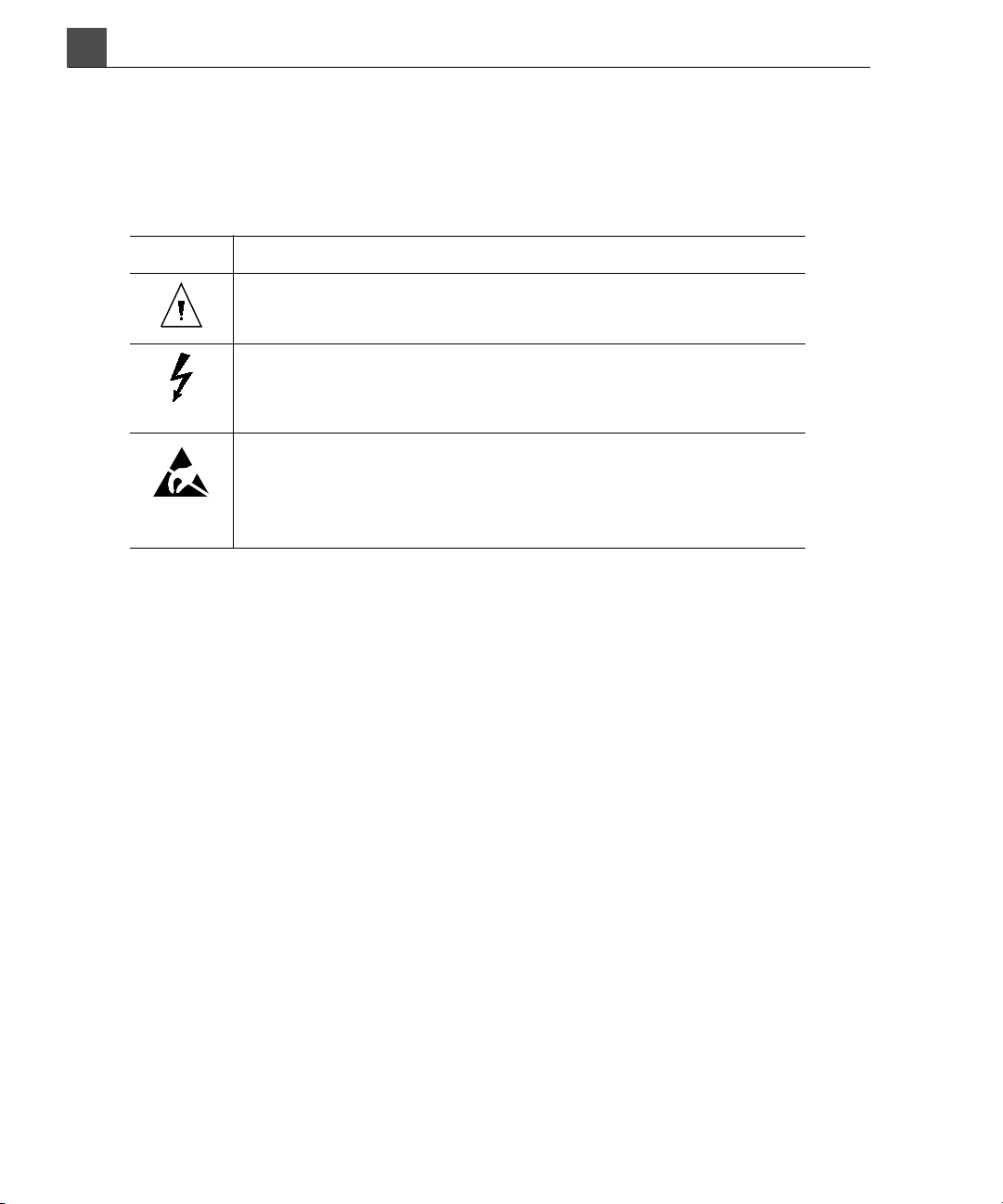
The system uses the following warning symbols (Table 1-1). For additional sym-
bols used on the system, see “Symbols Used on the System” on page 45.
Symbol Description
Documentation: The product is marked with this symbol
when it is necessary to refer to the user information.
Dangerous voltages: This symbol appears adjacent to
high-voltage terminals. It indicates the presence of voltages
greater than 1,000 Vac (600 Vac in the United States).
ESD (electrostatic discharge): The product is marked with this
symbol to warn the user not to touch exposed pins. Touching
exposed pins can cause electrostatic discharge, which can
damage the product.
Ta b l e 1 - 1 W a r n i n g S y m b o l s
About Your User Information
The user information provided with your system includes the following components:
• Compact Disc (CD): Includes all of the user information, except the Operat-
ing Notes.
• Getting Started: Introduces you to system features and concepts, and helps
you set up your ultrasound system. This manual also includes procedures for
basic operation. For detailed operating instructions, refer to Help or the User
Reference.
• Help: Help is available on the system in some languages and the information
in Help is also included in the User Reference on the CD. Help contains comprehensive instructions for using the system. Press Help on the system control panel to display Help. It includes a glossary containing descriptions of all
controls and display elements.
• Quick Guide: The Quick Guide is provided with the system and is also
included on the CD. It contains procedures, imaging tips, and information on
system controls.
HD11 XE Getting Started
16
4535 612 62651

• Acoustic Output Tables: Included on the CD, it contains information about
mechanical index (MI) and thermal index (TI) precision and accuracy, the
acoustic output default tables, and the acoustic output tables.
• Medical Ultrasound Safety: Included on the CD, it contains information on
bioeffects and biophysics, prudent use, and implementing ALARA (as low as
reasonably achievable).
• Operating Notes: Contains information that clarifies certain system
responses that might be misunderstood or cause user difficulty.
• Shared Roles for System and Data Security: Contains guidelines to help
you understand how the security of your ultrasound system could be compromised and information on Philips efforts to help you prevent security
breaches.
About Your Compact Disc
The CD contains all of the user information, except the Operating Notes. The
instructions for using the CD are included with the CD.
Read This First
1
Conventions
The system uses certain conventions throughout the interface to make it easy for
you to learn and use. The accompanying user information also uses typographical
conventions to assist you in finding and understanding information.
System Conventions
These conventions are used in the system:
• The trackball, the Enter key, and the Select key work together somewhat
like a computer mouse. Moving the trackball is like moving the mouse. Pressing the Enter key is like pressing the left mouse button. In Image Review,
pressing the Select key is like pressing the right mouse button.
• To enter text into a field, click in the field and use the keyboard.
•To display a list, click the down arrow. To scroll through a list, click the arrows
at either end of the scroll bar or drag the scroll bar up or down.
• Controls on the control panel include buttons, soft keys, hard keys, option
and record keys, knobs, slide controls, and a trackball. Press a button to acti-
HD11 XE Getting Started
4535 612 62651
17

Read This First
1
vate or deactivate its function. Turn a knob to change the selected setting.
Move a slide control to change its setting. Roll the trackball in the direction
that you want to move a caliper or object.
•The Point er control has multiple functions, depending on the mode: Press it
to show or hide the system pointer, to exit an active application, to start a
function from an icon on the Report and Review pages, or to select and view
thumbnails on the display.
User Information Conventions
The user information follows these conventions:
• Hypertext links appear in blue.
• All procedures are numbered, and all subprocedures are lettered. You must
complete steps in the sequence they are presented to ensure success.
• Bulleted lists indicate general information about a particular function or procedure. They do not imply a sequential procedure.
• Control names and menu items or titles are spelled as they are on the system,
and they appear in bold text.
• Symbols appear as they appear on the system.
• The left side of the system is to your left as you stand in front of the system,
• Transducers and pencil probes both are referred to as transducers, unless the
• Click means to move the pointer to an object and press the Enter key.
• Double-click means to quickly click twice to select an object or text.
• Select means to move the pointer to an object and press the Select key.
• Drag means to place the pointer over an object and then press and hold the
HD11 XE Getting Started
18
4535 612 62651
facing the system. The front of the system is nearest you as you operate it.
distinction is important to the meaning of the text.
Enter key while moving the trackball. Use this method to move an object on
the display.

Read This First
Information that is essential for the safe and effective use of the ultrasound system
appears throughout your system user information as follows:
1
NOTE
Notes bring your attention to important information that will help you operate
the ultrasound system more effectively.
CAUTION
Cautions highlight ways that you could damage your ultrasound system and consequently void your warranty or service contract.
WARNING
Warnings highlight information vital to the safety of you, the operator, and the
patient.
Upgrades and Updates
Philips Ultrasound is committed to innovation and continued improvement.
When upgrades that consist of hardware or software improvements are released,
updated user information sets will accompany those system upgrades.
Customer Comments
If you have questions about the user information set, or to report an error in the
user information set
• For U.S. customers, call Philips Ultrasound Customer Service at
800-722-9377.
• For customers outside the USA, call your local customer service representative or contact one of the offices under “Customer Service” on page 20.
You can also send e-mail to Philips Ultrasound Technical Communications at the
following address:
bothell.techpubs@philips.com
HD11 XE Getting Started
4535 612 62651
19

Read This First
1
Ordering Supplies and Accessories
You can order transducer covers, biopsy guides, and other supplies and accessories from CIVCO Medical Instruments:
CIVCO Medical Instruments
102 First St. South
Kalona, IA 52247-9589
Telephone: 800-445-6741, Ext. 1 for Customer Service (USA)
+1 319-656-4447 (International)
Fax: 877-329-2482 (USA)
+1 319-656-4451 (International)
E-mail: info@civcomedical.com
Internet: civco.com
For more information on ordering supplies and accessories, see “HD11 XE Sys-
tem Supplies, Peripherals, and Accessories” on page 259.
Customer Service
Customer service representatives are available worldwide to answer questions
and to provide maintenance and service. Please contact your local Philips Ultrasound representative for assistance. You can also contact one of the following
offices for referral to a customer service representative, or visit the Philips Ultrasound Web site:
www.medical.philips.com
Corporate and North American Headquarters
22100 Bothell-Everett Highway
Bothell, WA 98021-8431
USA
800-722-9377
HD11 XE Getting Started
20
4535 612 62651

Read This First
Asia Pacific Headquarters
Level 9, Three Pacific Place
1 Queen’s Road East
Wanchai
Hong Kong
+852 2821 5888
European Headquarters (also serves Africa and the Middle East)
Philips Medizin Systeme Böblingen GmbH
Hewlett-Packard-Str. 2
71034 Böblingen
Germany
+49 40 5078 4532
Latin American Headquarters
1550 Sawgrass Corporate Parkway, Suite 300
Sunrise, FL 33323
USA
1
+1 954-628-1000
HD11 XE Getting Started
4535 612 62651
21

1
Read This First
HD11 XE Getting Started
22
4535 612 62651

2Safety
Read this section before you use the ultrasound system. Also refer to the Quick
Guide and the Help.
Before you use any transducer for the first time, be sure to read all applicable
usage, patient-safety, operator-safety, and electrical-safety guidelines in this manual.
If you have any comments or questions about safety, contact your Philips representative.
This section includes critical information about the intended uses of the ultrasound system.
Dangerous Voltages Symbol
The dangerous voltages symbol appears adjacent to high-voltage terminals.
It indicates the presence of voltages greater than 1,000 Vac (600 Vac in the United
States).
Warnings
Before using the system, read the following warnings and this “Safety” section:
Electrical Shock Hazard
WARNING
Do not remove system covers. To avoid electrical shock, use only supplied power
cords and connect only to properly grounded wall (wall/mains) outlets. For more
information regarding operator and patient safety, see “Electrical Warnings” on
page 48.
HD11 XE Getting Started
4535 612 62651
23

Safety
2
Explosion Hazard
WARNING
Do not operate the system in the presence of flammable anesthetics. For more
information regarding operator and patient safety, see “Explosive Hazards” on
page 52.
Radio Frequency Communications Equipment Hazard
WARNING
The use of portable and mobile RF communications equipment can affect the
operation of medical equipment.
Electromagnetic Compatibility
Electromagnetic compatibility (EMC) is defined as the ability of a product, a device,
or a system to function satisfactorily in the presence of the electromagnetic phenomena that exists in the location of the product, the device, or the system being
used; and, in addition, to not introduce intolerable electromagnetic disturbances
to anything in that same environment.
Electromagnetic immunity is the ability of a product, a device, or a system to function satisfactorily in the presence of electromagnetic interference (EMI).
Electromagnetic emissions is the ability of a product, a device, or a system to introduce intolerable electromagnetic disturbances into the use environment.
The ultrasound system has been manufactured in compliance with existing electromagnetic compatibility requirements. Use of this system in the presence of an
electromagnetic field can cause momentary degradation of the ultrasound image.
If this occurs often, review the environment in which the system is being used to
identify possible sources of radiated emissions. These emissions could be from
other electrical devices used within the same room or an adjacent room, or from
portable and mobile RF communications equipment such as cellular phones and
pagers, or from the existence of radio, TV, or microwave transmission equipment
located nearby. In cases where electromagnetic interference (EMI) is causing disturbances, it may be necessary to relocate your system.
HD11 XE Getting Started
24
4535 612 62651

The system complies with International Standard CISPR 11 for radiated and conducted electromagnetic disturbances. Compliance with this standard allows the
system to be used in all establishments, including domestic establishments and
those directly connected to the public low-voltage power supply network that
supplies buildings used for domestic purposes.
CAUTION
Medical equipment has special precautions regarding EMC and needs to be
installed and put into service according to the EMC information provided in the
system’s accompanying documents.
“Electromagnetic Compatibility” on page 127 includes information on electro-
magnetic emissions and immunity as it applies to the system. Ensure that the
operating environment of your system meets the conditions specified in the referenced information. Operating the system in an environment that does not meet
these conditions may degrade system performance.
The information and warnings contained in this and other sections should be
observed when installing and using the ultrasound system to ensure its EMC.
Safety
2
The ultrasound system will remain safe and will provide the following essential
performance if it is operated within the electromagnetic environment listed in
Table 6-6 on page 131:
• Imaging (See “Electromagnetic Compatibility” on page 127 for conducted
immunity limitations and rationale.)
• Doppler audio and spectral display
•Measurements
• Acoustic output
• ECG triggering
• VCR recording and playback
• Printing using the system printers
• Patient information
• Date/time information
HD11 XE Getting Started
4535 612 62651
25

Safety
2
WARNING
Using cables, transducers, or accessories with the system other than those specified for use with the system may result in increased emissions or decreased
immunity of the system.
ECG Signal
The amplitude of the electrocardiogram (ECG) signal is critical for reliable frame
triggering. Frame triggering should only be used when a clean, noise-free ECG
waveform is observed on the ECG display.
The ECG signal should be at least 0.25 mV to ensure reliable triggering when the
system is used in the presence of the electromagnetic phenomena described in
this manual.
WARNING
Operation of your system below 0.25 mV may cause inaccurate results. See
“ECG/Physio Input Connections” on page 142 for more information.
Electrostatic Discharge Precautions
Electrostatic discharge (ESD), commonly referred to as a static shock, is a naturally occurring phenomenon. ESD is most prevalent during conditions of low
humidity, which can be caused by heating or air-conditioning. During low humidity
conditions, electrical charges naturally build up on individuals and objects and can
create static discharges.
HD11 XE Getting Started
26
4535 612 62651

The following cautions can help to reduce ESD effect:
W
CAUTIONS
• Do not touch transducer connector pins or the system’s transducer recepta-
cle.
• Handle the transducer by the metal connector shell.
• Make contact with a metal surface of the system before connecting a trans-
ducer to the system.
• On connectors that display the ESD sensitivity symbol , do not touch the
connector pins, and always observe the preceding ESD precautions when handling or connecting transducers. For more information, see “Electrostatic Dis-
charge Guidelines” on page 120.
Biological Safety
This section contains information about biological safety and a discussion of the
prudent use of the system.
A list of precautions related to biological safety follows; observe these precautions when using the system. For more information refer to Medical Ultrasound
Safety on your user information CD.
Safety
2
ARNINGS
• Do not use the system if an error message appears on the video display indi-
cating that a hazardous condition exists. Note the error code, turn off power
to the system, and call your customer service representative.
• Do not use a system that exhibits erratic or inconsistent image updating. Dis-
continuities in the scanning sequence are indicative of a hardware failure that
must be corrected before use.
• Perform ultrasound procedures prudently. Use the ALARA (as low as reason-
ably achievable) principle.
HD11 XE Getting Started
4535 612 62651
27

Safety
W
2
ARNINGS
• Use only acoustic standoffs that have been approved by Philips Ultrasound.
• Transducer covers may contain natural rubber latex. Those covers may cause
allergic reactions in some individuals. Refer to the FDA Medical Alert on Latex
Products, dated March 29, 1991.
• In contrast studies using a high-MI acoustic field, capillary rupture, due to
microbubble expansion within a capillary in an acoustic field, can cause
extravasation.
• Preventricular contractions can be caused by the oscillations of microbubbles
when a high-MI acoustic field is triggered in the heart at the end of systole. In
a very sick patient with certain risk factors, theoretically, this could lead to
ventricular fibrillation. References: 1. Skyba DM, Price RJ, Linka AZ, Skalak
TC, Kaul S. Direct in vivo visualization of intravascular destruction of microbubbles
by ultrasound and its local effects on tissue. Circulation 1998;98:290-293. 2. van
Der Wouw PA, Brauns AC, Bailey SE, Powers JE, Wilde AA. Premature ventric-
ular contractions during triggered imaging with ultrasound contrast. J Am Soc
Echocardiogr 2000;13(4):288-94.
• If the sterile transducer cover becomes compromised during an intraopera-
tive application involving a patient with Creutzfeldt-Jakob disease, follow the
recommendations described in “Transmissible Spongiform Encephalopathy”
on page 54.
• If the system becomes contaminated internally with bodily fluids carrying
• The backlight lamps in the system displays contain mercury and must be recy-
ALARA Education Program
The guiding principle for the use of diagnostic ultrasound is defined by the “as low
as reasonably achievable” (ALARA) principle. The decision as to what is reasonable has been left to the judgement and insight of qualified personnel. No set of
rules can be formulated that would be sufficiently complete to dictate the correct
HD11 XE Getting Started
28
4535 612 62651
pathogens, you must immediately notify your Philips Ultrasound service representative. The system’s internal components cannot be disinfected. In this
case, the system must be disposed of as biohazardous material in accordance
with local or federal laws.
cled or disposed of according to local, state, or federal laws.

Safety
response to every circumstance. By keeping ultrasound exposure as low as possible, while obtaining diagnostic images, users can minimize ultrasonic bioeffects.
Since the threshold for diagnostic ultrasound bioeffects is undetermined, it is the
sonographer’s responsibility to control total energy transmitted into the patient.
The sonographer must reconcile exposure time with diagnostic image quality. To
ensure diagnostic image quality and limit exposure time, an ultrasound system
provides controls that can be manipulated during the exam to optimize the
results of the exam.
The ability of the user to abide by the ALARA principle is important. Advances in
diagnostic ultrasound not only in the technology but in the applications of that
technology, have resulted in the need for more and better information to guide
the user. The output display indices are designed to provide that important information.
There are a number of variables which affect the way in which the output display
indices can be used to implement the ALARA principle. These variables include
index values, body size, location of the bone relative to the focal point, attenuation in the body, and ultrasound exposure time. Exposure time is an especially
useful variable, because it is controlled by the user. The ability to limit the index
values over time supports the ALARA principle.
2
Applying ALARA
The system imaging mode used depends upon the information needed. 2D and
M-mode imaging provide anatomical information, while Doppler, Philips Color
Power Angio (CPA), and Color imaging provide information about blood flow. A
scanned mode, like 2D, CPA, or Color, disperses or scatters the ultrasonic energy
over an area, while an unscanned mode, like M-mode or Doppler, concentrates
ultrasonic energy. Understanding the nature of the imaging mode being used
allows the sonographer to apply the ALARA principle with informed judgement.
Additionally, the transducer frequency, system setup values, scanning techniques,
and operator experience allow the sonographer to meet the definition of the
ALARA principle.
Special care must be taken to enter the correct application when conducting an
exam, and to remain in that application throughout the course of that examination. In the future, HD11 XE may add some applications, such as ophthalmic appli-
HD11 XE Getting Started
4535 612 62651
29

Safety
2
cations, dealing with delicate parts of the body which require lower limits for
acoustic output.
The decision as to the amount of acoustic output is, in the final analysis, up to the
system operator. This decision must be based on the following factors: type of
patient, type of exam, patient history, ease or difficulty of obtaining diagnostically
useful information, and the potential localized heating of the patient due to transducer surface temperatures. Prudent use of the system occurs when patient
exposure is limited to the lowest index reading for the shortest amount of time
necessary to achieve acceptable diagnostic results.
Although a high index reading does not mean that a bioeffect is actually occurring,
a high index reading should be taken seriously. Every effort should be made to
reduce the possible effects of a high index reading. Limiting exposure time is an
effective way to accomplish this goal.
There are several system controls that the operator can use to adjust the image
quality and limit the acoustic intensity. These controls are related to the techniques that an operator might use to implement ALARA. These controls can be
divided into three categories: direct, indirect, and receiver controls.
Direct Controls
Application selection and the Power control directly affect acoustic intensity.
There are different ranges of allowable intensity or output based on your selection. Selecting the correct range of acoustic intensity for the application is one of
the first things that occurs in any exam. For example, peripheral vascular intensity
levels are not recommended for fetal exams. Some systems automatically select
the proper range for a particular application, while others require manual selection. Ultimately, the user has the responsibility for proper clinical use. The ultrasound system provides both automatic (default) settings and manual
(user-selectable) settings.
Power has direct impact on acoustic intensity. Once the application has been
established, the Power control can be used to increase or decrease the intensity
output. The Power control allows you to select intensity levels less than the
established maximum. Prudent use dictates that you select the lowest output
intensity that is consistent with good image quality.
HD11 XE Getting Started
30
4535 612 62651

Safety
2
Indirect Controls
The indirect controls are those that have an indirect effect on acoustic intensity.
These controls affect imaging mode, pulse repetition frequency, focus depth, pulse
length, and transducer selection.
The choice of imaging mode determines the nature of the ultrasound beam. 2D is
a scanning mode, Doppler is a stationary or unscanned mode. A stationary ultrasound beam concentrates energy in a single location. A moving or scanned ultrasound beam disperses the energy over an area and the beam is concentrated on
the same area for a fraction of the time as that of an unscanned mode.
Pulse repetition frequency or rate refers to the number of ultrasound bursts of
energy over a specific period of time. The higher the pulse repetition frequency,
the more pulses of energy in a period of time. Several controls affect pulse repetition frequency: focal depth, display depth, gate depth, scale, number of focal
zones, and sector width controls.
Focus of the ultrasound beam affects the image resolution. To maintain or
increase resolution at a different focus requires a variation in output over the
focal zone. This variation of output is a function of system optimization. Different
exams require different focal depths. Setting the focus at the proper depth
improves the resolution of the structure of interest.
Pulse length is the time during which the ultrasonic burst is turned on. The longer
the pulse, the greater the time-average intensity value. The greater the time-average intensity, the greater the likelihood of temperature increase and cavitation.
Pulse length or burst length or pulse duration is the output pulse duration in
pulsed Doppler. Increasing the Doppler gate length increases the pulse length.
Transducer selection indirectly affects intensity. Tissue attenuation changes with
frequency. The higher the transducer operating frequency, the greater the attenuation of the ultrasonic energy. A higher transducer operating frequency requires
more output intensity to scan at a deeper depth. To scan deeper at the same output intensity, a lower transducer frequency is required. Using more gain and output beyond a point, without corresponding increases in image quality, can mean
that a lower frequency transducer is needed.
HD11 XE Getting Started
4535 612 62651
31

Safety
2
Receiver Controls
Receiver controls are used by the operator to improve image quality. These controls have no effect on output. Receiver controls only affect how the ultrasound
echo is received. These controls include gain, TGC, dynamic range, and image
processing. The important thing to remember, relative to output, is that receiver
controls should be optimized before output is increased. For example: before
increasing output, optimize gain to improve image quality.
An Example of Applying ALARA
An ultrasound scan of a patient’s liver begins with selecting the appropriate transducer frequency. After selecting the transducer and the application, which are
based on patient anatomy, adjustments to output power should be made to
ensure that the lowest possible setting is used to acquire an image. After the
image is acquired, adjusting the focus of the transducer, and then increasing the
receiver gain to produce a uniform representation of the tissue follows. If an adequate image can be obtained with the increase in gain, then a decrease in output
should be made. Only after making these adjustments should you increase output
to the next level.
Having acquired the 2D display of the liver, Color can be used to localize blood
flow. As with the 2D image display, gain and image processing controls must be
optimized before increasing output.
Having localized the blood flow, use the Doppler controls to position the gate
over the vessel. Before increasing output, adjust velocity range or scale and Doppler gain to obtain an optimal Doppler trace. Only if maximum Doppler gain does
not create an acceptable image do you increase output.
In summary: select the correct transducer frequency and application for the job;
start with a low output level; optimize the image using focus, receiver gain, and
other imaging controls; if the image is not diagnostically useful at this point, then
increase output.
Additional Considerations
Ensure that scanning time is kept to a minimum, and ensure that only medically
required scanning is performed. Never compromise quality by rushing through an
exam. A poor exam may require a follow-up, which ultimately increases exposure
HD11 XE Getting Started
32
4535 612 62651

Safety
time. Diagnostic ultrasound is an important tool in medicine, and, like any tool, it
should be used efficiently and effectively.
2
Output Display
The system output display comprises two basic indices: a mechanical index and a
thermal index. The thermal index further consists of the following indices: soft
tissue (TIS), bone (TIB), and cranial bone (TIC). One of these three thermal indices will be displayed at all times. Which one depends upon the system preset or
user choice, depending upon the application at hand.
The mechanical index (MI) is continuously displayed over the range of 0.0 to maximum output (see the HD11 XE Acoustic Output Tables), in increments of 0.1 for all
applications except contrast, where the minimum increment is 0.01.
The thermal index consists of the three indices, and only one of these is displayed
at any one time. Each transducer application has a default selection that is appropriate for that combination. The TIB, TIS, or TIC is continuously displayed over
the range of 0.0 to maximum output, based on the transducer and application, in
increments of 0.1.
The decision as to which of the three thermal indices to display should be based
on the following criteria:
• Appropriate index for the application: TIS is used for imaging soft tissue, TIB
for a focus at or near bone, and TIC for imaging through bone near the surface, as in a cranial exam.
•Mitigating factors that might create artificially high or low thermal index readings: location of fluid or bone, or blood flow. For example, is there a highly
attenuating tissue path so that the actual potential for local zone heating is less
than the thermal index displays.
• Scanned modes versus unscanned modes of operation affect the thermal
index. For scanned modes, heating tends to be near the surface; for
unscanned modes, the potential for heating tends to be deeper in the focal
zone.
• Always limit ultrasound exposure time. Do not rush the exam. Ensure that
the indices are kept to a minimum and that exposure time is limited without
compromising diagnostic sensitivity.
HD11 XE Getting Started
4535 612 62651
33

Safety
2
Mechanical Index (MI) Display
Mechanical bioeffects are threshold phenomena that occur when a certain level of
output is exceeded. The threshold level varies, however, with the type of tissue.
The potential for mechanical bioeffects varies with peak rarefactional pressure
and ultrasound frequency. The MI accounts for these two factors. The higher the
MI value, the greater the likelihood of mechanical bioeffects occurring. There is
no specific MI value that means that a mechanical effect is actually occurring. The
MI should be used as a guide for implementing the ALARA principle.
Thermal Index (TI) Displays
The TI informs the user about the conditions that exist that might lead to an
increase in temperature at the surface of the body, within the body tissue, or at
the point of focus of the ultrasound beam on bone. That is, the TI informs the
user of the potential for temperature rise in body tissue. It is an estimate of temperature increase in body tissue with specific properties. The actual amount of
any temperature rise is influenced by factors such as tissue type, vascularity, mode
of operation and others. The TI should be used as a guide for implementing the
ALARA principle.
The bone thermal index (TIB) informs the user about potential heating at or near
the focus after the ultrasound beam has passed through soft tissue or fluid, for
example, at or near second or third trimester fetal bone.
The cranial bone thermal index (TIC) informs the user about the potential heating
of bone at or near the surface, for example, cranial bone.
The soft tissue thermal index (TIS) informs the user about the potential for heating within soft homogeneous tissue.
➤ To display TIS, TIC, or TIB
1. Press Setup.
2. In the System widow, click the System tab.
3. Under Thermal Index, select the appropriate index.
4. Click Close.
TIC is displayed when you select a transcranial application.
HD11 XE Getting Started
34
4535 612 62651

Safety
2
Mechanical and Thermal Indices Display Precision and Accuracy
The MI and TI precision is 0.1 unit on the system.
For system MI and TI display accuracy estimates, see the HD11 XE Acoustic Output
Tabl es . These accuracy estimates are based on the variability range of transducers
and systems, inherent acoustic output modeling errors and measurement variability, as discussed below.
The displayed values should be interpreted as relative information to help the system operator achieve the ALARA principle through prudent use of the system.
The values should not be interpreted as actual physical values in interrogated tissue or organs. The initial data that is used to support the output display is derived
from laboratory measurements based on the American Institute of Ultrasound in
Medicine (AIUM) measurement standard. The measurements are then put into
algorithms for calculating the displayed output values.
Many of the assumptions used in the process of measurement and calculation are
conservative in nature. Over-estimation of actual in situ intensity exposure, for
the vast majority of tissue paths, is built into the measurement and calculation
process. For example:
• The measured water tank values are derated using a conservative, industry
standard, attenuation coefficient of 0.3 dB/cm-MHz.
• Conservative values for tissue characteristics were selected for use in the TI
models. Conservative values for tissue or bone absorption rates, blood perfusion rates, blood heat capacity, and tissue thermal conductivity were selected.
• Steady State temperature rise is assumed in the industry standard TI models,
and the assumption is made that the ultrasound transducer is held steady in
one position long enough for steady state to be reached.
A number of factors are considered when estimating the accuracy of the displayed
values: hardware variations, estimation algorithm accuracy, and measurement
variability. Variability among transducers and systems is a significant factor. Transducer variability results from piezoelectric crystal efficiencies, process-related
impedance differences, and sensitive lens focusing parameter variations. Differences in system pulser voltage control and efficiencies is also a contributor to
variability. There are inherent uncertainties in the algorithms used to estimate
acoustic output values over the range of possible system operating conditions and
pulser voltages. Inaccuracies in laboratory measurements are related to, among
HD11 XE Getting Started
4535 612 62651
35

Safety
2
others, differences in hydrophone calibration and performance, positioning, alignment, and digitization tolerances, and variability among test operators.
The conservative assumptions of the output estimation algorithms of linear propagation, at all depths, through a 0.3 dB/cm-MHz attenuative medium is not considered in the accuracy estimate for the display. Neither linear propagation, nor
uniform attenuation at the 0.3 dB/cm-MHz rate, occur in water tank measurements or in most tissue paths in the body. In the body, different tissues and organs
have dissimilar attenuation characteristics. In water, there is almost no attenuation. In the body, and in particular, in water tank measurements, non-linear propagation and saturation losses occur as pulser voltages increase.
Therefore, the display accuracy estimates are based on the variability range of
transducers and systems, inherent acoustic output modeling errors, and measurement variability. Display accuracy estimates are not based on errors in, or caused
by measuring according to, the AIUM measurement standards, or the effects of
non-linear loss on the measured values.
Control Effects
Controls Affecting the Indices
As various system controls are adjusted, the TI and MI values may change. This
will be most apparent as the Power control is adjusted; however, other system
controls will affect the on-screen output values.
Power
Power controls the system acoustic output. Two real-time output values are on
the screen: a TI and MI. They change as the system responds to Power adjustments.
In combined modes, such as Triplex (simultaneous Color, 2D, and pulsed-wave
Doppler), the individual modes each add to the total TI. One mode will be the
dominant contributor to this total. The displayed MI will be from the mode with
the largest MI value.
HD11 XE Getting Started
36
4535 612 62651

Safety
2
2D Controls
Sector Width
Narrowing the sector angle may increase frame rate. This action will increase the
TI. Pulser voltage may be automatically adjusted down with software controls to
keep the TI below the system maximums. A decrease in pulser voltage will
decrease MI.
Zoom
Increasing the zoom magnification by pressing Zoom may increase frame rate.
This action will increase the TI. The number of focal zones may also increase
automatically to improve resolution. This action may change MI since a different
focal zone may now produce the largest MI value.
Number of Focal Zones
More focal zones may change both the TI and MI by changing frame rate or focal
depth automatically. Lower frame rates decrease the TI. MI displayed will correspond to the zone with the largest MI value.
Focus
Changing the focal depth will change MI. Generally, higher MI values will occur
when the focal depth is near the natural focus of the transducer.
Color and Power Controls
Color Sector Width
Narrower color sector width will increase color frame rate and the TI will
increase. The system may automatically decrease pulser voltage to stay below the
system maximum. A decrease in pulser voltage will decrease the MI. If pulsed
Doppler is also enabled then pulsed Doppler will remain the dominant mode and
the TI change will be small.
Color Sector Depth
Deeper color sector depth may automatically decrease color frame rate or select
a new color focal zone or color pulse length. The TI will change due to the combination of these effects. Generally, the TI will decrease with increased color sector depth. MI will correspond to the peak MI value of the dominant pulse type
HD11 XE Getting Started
4535 612 62651
37

Safety
2
which is a color pulse. However, if pulsed Doppler is also enabled then pulsed
Doppler will remain the dominant mode and the TI change will be small.
Scale
Using the scale control to increase the color velocity range may increase the TI.
The system may automatically adjust pulser voltage to stay below the system maximums. A decrease in pulser voltage will also decrease MI.
Sector Width
A narrower 2D sector width in Color imaging will increase color frame rate. The
TI will increase. MI will not change. If pulsed Doppler is also enabled, then pulsed
Doppler will remain the dominant mode and the TI change will be small.
M-mode and Doppler Controls
Combination Modes
Use of combination modes affects both the TI and MI through the combination of
pulse types. During duplex, the TI will display the dominant pulse type. The displayed MI will be from the mode with the largest MI value.
Gate Depth
When Doppler gate depth is increased the Doppler PRF may automatically
decrease. An increase in PRF will increase the TI. The system may also automatically decrease the pulser voltage to remain below the system maximum. A
decrease in pulser voltage will decrease MI.
Other
2D, Color, M-mode, CPA, PW, and CW
When a new imaging mode is selected, both the TI and MI may change to default
settings. Each mode has a corresponding pulse repetition frequency and maximum
intensity point. In combined or simultaneous modes, the TI is the sum of the contribution from the modes enabled and the displayed MI is the largest of the MI values associated with each mode and focal zone enabled. The system will return to
the previously selected state if a mode is turned off and then reselected.
HD11 XE Getting Started
38
4535 612 62651

Safety
Transducer
Each transducer type has unique specifications for contact area, beam shape, and
center frequency. Presets are initialized in 2D mode when you select a transducer.
Factory presets vary with transducer and selected mode. With each new transducer selected, the MI and TI displayed values are likely to change.
Depth
An increase in 2D depth will automatically decrease the 2D frame rate. This
would decrease the TI. The system may also automatically choose a deeper 2D
focal depth. A change of focal depth may change the MI. The MI displayed is that
of the zone with the largest MI value.
Preset
Factory presets vary with transducer and selected mode. A change in preset
while a transducer is active will change some of the controls listed above, which
can change the MI and TI values in the ways indicated for each relevant control.
2
Related Guidance Documents
For more information about ultrasonic bioeffects and related topics, see the following:
1. AIUM Report, January 28, 1993, “Bioeffects and Safety of Diagnostic Ultrasound”
2. Bioeffects Considerations for the Safety of Diagnostic Ultrasound, J Ultrasound
Med., Sept. 1988: Vol. 7, No. 9 Supplement
3. Acoustic Output Measurement Standard for Diagnostic Ultrasound Equipment. (AIUM, NEMA. 1998)
4. Acoustic Output Labeling Standard for Diagnostic Ultrasound Equipment
(AIUM, 1998)
5. Second Edition of the AIUM Output Display Standard Brochure, Dated March
10, 1994. (A copy of this document is provided with each system.)
6. Information for Manufacturers Seeking Marketing Clearance of Diagnostic
Ultrasound Systems and Transducers. FDA. September 1997. FDA.
HD11 XE Getting Started
4535 612 62651
39

Safety
2
7. Standard for Real-Time Display of Thermal and Mechanical Acoustic Output
Indices on Diagnostic Ultrasound Equipment. (Revision 1, AIUM, NEMA.
1998)
8. WFUMB. Symposium on Safety of Ultrasound in Medicine: Conclusions and
Recommendations on Thermal and Non-Thermal Mechanisms for Biological
Effects of Ultrasound, Ultrasound in Medicine and Biology, 1998: Vol. 24, Supplement 1.
Acoustic Output and Measurement
Since the initial use of diagnostic ultrasound, the possible human biological effects
(bioeffects) from ultrasound exposure have been studied by various scientific and
medical institutions. In October 1987, the American Institute of Ultrasound in
Medicine (AIUM) ratified a report prepared by its Bioeffects Committee (Bioeffects Considerations for the Safety of Diagnostic Ultrasound, J Ultrasound Med.,
Sept. 1988: Vol. 7, No. 9 Supplement), sometimes referred to as the Stowe
Report, which reviewed available data on possible effects of ultrasound exposure.
Another report “Bioeffects and Safety of Diagnostic Ultrasound,” dated January
28, 1993, provides more current information.
The acoustic output for this system has been measured and calculated in accordance with the “Acoustic Output Measurement Standard for Diagnostic Ultrasound Equipment” (AIUM, NEMA 1998), the “Standard for Real-Time Display of
Thermal and Mechanical Acoustic Output Indices on Diagnostic Ultrasound
Equipment” (Revision 1, AIUM, NEMA 1998), and the September, 1997 FDA document “Information for Manufacturers Seeking Marketing Clearance of Diagnostic
Ultrasound Systems and Transducers.”
HD11 XE Getting Started
40
4535 612 62651

Safety
2
In Situ, Derated, and Wate r Value Intensities
All intensity parameters are measured in water. Since water absorbs very little
acoustic energy, these water measurements represent a worst case value. Biological tissue does absorb acoustic energy. The true value of the intensity at any
point depends on the amount and type of tissue and the frequency of the ultrasound that passes through the tissue. The intensity value in the tissue, In Situ, has
been estimated by using the following formula:
In Situ = Water [e
Where: In Situ = In Situ Intensity Value
Water = Water Value Intensity
e=2.7183
a = Attenuation Factor
Tissue = a(dB/cm-MHz)
-0.23alf
]
Amniotic
Fluid
Brain = 0.53
Heart = 0.66
Kidney = 0.79
Liver = 0.43
Muscle = 0.55
Since the ultrasonic path during an examination is likely to pass through varying
lengths and types of tissue, it is difficult to estimate the true In Situ intensity. An
attenuation factor of 0.3 is used for general reporting purposes; therefore, the In
Situ value which is commonly reported uses the formula:
Since this value is not the true In Situ intensity, the term “derated” is used.
= 0.006
l = Skin line to measurement depth (cm)
f=Center frequency of the transducer/system/mode
combination (MHz)
-0.069lf
In Situ derated = Water [e
]
HD11 XE Getting Started
4535 612 62651
41

Safety
2
Mathematical derating of water based measurements using the 0.3 dB/cm-MHz
coefficient, may yield lower acoustic exposure values than would be measured in a
homogenous 0.3 dB/cm-MHz tissue. This is true because non-linearly propagating
acoustic energy waveforms experience more distortion, saturation, and absorption in water than in tissue, where attenuation present all along the tissue path
will dampen the buildup of non-linear effects.
The maximum derated and the maximum water values do not always occur at the
same operating conditions; therefore, the reported maximum water and derated
values may not be related by the In Situ (derated) formula. For example: a
multi-zone array transducer that has maximum water value intensities in its deepest zone may have its largest derated intensity in one of its shallowest focal zones.
Conclusions Regarding Tissue Models and Equipment Survey
Tissue models are necessary to estimate attenuation and acoustic exposure levels
In Situ from measurements of acoustic output made in water. Presently, available
models may be limited in their accuracy because of varying tissue paths during
diagnostic ultrasound exposures and uncertainties in acoustical properties of soft
tissues. No single tissue model is adequate for predicting exposures in all situations from measurements made in water, and continued improvement and verification of these models is necessary for making exposure assessments for specific
applications.
A homogeneous tissue model with an attenuation coefficient of 0.3 dB/cm-MHz
throughout the beam path is commonly used when estimating exposure levels.
The model is conservative in that it overestimates the In Situ acoustic exposure
when the path between the transducer and the site of interest is composed
entirely of soft tissue, because the attenuation coefficient of soft tissue is generally
higher than 0.3 dB/cm-MHz. When the path contains significant amounts of fluid,
as in many first and second-trimester pregnancies scanned transabdominally, this
model may underestimate the In Situ acoustical exposure. The amount of underestimation depends on each specific situation. For example, when the beam path
is longer than 3 cm and the propagation medium is predominantly fluid (conditions that may exist during transabdominal OB scans), a more accurate value for
the derating term is 0.1 dB/cm-MHz.
Fixed-path tissue models, in which soft tissue thickness is held constant, sometimes are used to estimate In Situ acoustical exposures when the beam path is
HD11 XE Getting Started
42
4535 612 62651

Safety
longer than 3 cm and consists largely of fluid. When this model is used to estimate maximum exposure to the fetus during transabdominal scans, a value of
1 dB/MHz may be used during all trimesters.
The maximum acoustic output levels of diagnostic ultrasound devices extend over
a broad range of values:
• A survey of 1990-equipment models yielded mechanical index (MI) values
between 0.1 and 1 at their highest output settings. Maximum MI values of
approximately 2 are known to occur for currently available equipment. Maximum MI values are similar for real-time 2D, M-mode, pulsed Doppler, and
Color flow imaging.
• Computed estimates of upper limits to temperature elevations during transabdominal scans were obtained in a survey of 1988 and 1990 pulsed Doppler
equipment. The vast majority of models yielded upper limits less than
1 degree C and 4 degrees C for exposures of first-trimester fetal tissue and
second-trimester fetal bone, respectively. The largest values obtained were
approximately 1.5 degrees C for first-trimester fetal tissue and 7 degrees C
for second-trimester fetal bone. Estimated maximum temperature elevations
given here are for a “fixed-path” tissue model and are for devices having I
2
SPTA
values greater than 500 mW/cm2. The temperature elevations for fetal bone
and tissue were computed based on calculation procedures given in Sections
4.3.2.1-4.3.2.6 in Bioeffects and Safety of Diagnostic Ultrasound (AIUM, 1993).
Acoustic Output Tables
Acoustic output tables are in the HD11 XE Acoustic Output Tables manual.
Acoustic Measurement Precision and Uncertainty
All table entries have been obtained at the same operating conditions that give
rise to the maximum index value in the first column of the tables. Measurement
precision and uncertainty for power, pressure, intensity, and center frequency are
shown in Table 2-1 and Table 2-2.
HD11 XE Getting Started
4535 612 62651
43

Safety
2
Ta b l e 2 - 1 A c o u s t i c M e a s u r e m e n t P re c i s i o n
NOTE
Per Section 6.4 of the Output Display Standard, measurement precision on the
following quantities is determined by making repeated measurements and stating
the standard deviation as a percentage.
Quantity
Pr is the underated peak rarefactional
pressure measured in MegaPascals.
Wo is the ultrasonic power in
milliWatts.
fc is the center frequency in MHz
(NEMA UD-2 definition).
PII.3 is the derated spatial-peak pulse
intensity integral in Joules/cm2.
Table 2-2 Acoustic Measurement Uncertainty
Quantity
Precision
(Percentage Standard Deviation)
Pr: 5.4%
6.2%
<1%
PII.3: 3.2%
Measurement Uncertainty
(percentage, 95% confidence
value)
Pr is the underated peak rarefactional
pressure measured in MegaPascals.
Wo is the ultrasonic power in
milliWatts.
is the center frequency in MHz
f
c
(NEMA UD-2 definition).
PII.3 is the derated spatial-peak pulse
intensity integral in Joules/cm
HD11 XE Getting Started
44
4535 612 62651
Pr ± 11.3%
± 10%
± 4.7%
PII.3: +18% to -23%
2
.

Symbols Used on the System
Table 2-3 lists the symbols used on the ultrasound system and their meanings.
Table 2-3 Symbols Used on the System
Symbol Meaning Description
Type BF The patient-applied part provides a degree of protection
from electrical shock. Suitable for external and internal
application to the patient, excluding direct cardiac
application. The patient-applied part is floating (isolated)
from earth ground.
Type CF The patient-applied part provides a degree of protection
from electrical shock. Suitable for all patient-applied
applications including direct cardiac applications. The
patient-applied part is floating (isolated) from earth ground.
Safety
2
Ty p e CF
Defibrillator
Proof
Attention See the accompanying documentation.
Dangerous
voltages
Input The connector near either of these symbols receives an
Output The connector near this symbol sends an outgoing signal.
Alternating
current
Ground Protective earth ground.
The patient-applied part provides a degree of protection
from electrical shock. This symbol indicates that the
patient-applied part is defibrillator proof. The patient-applied
part is suitable for all patient applications including direct
cardiac applications.
This symbol appears adjacent to high-voltage terminals. It
indicates the presence of voltages greater than 1,000 Vac
(600 Vac in the United States).
incoming signal.
The connector near this symbol receives alternating
voltages.
HD11 XE Getting Started
4535 612 62651
45

Safety
2
Table 2-3 Symbols Used on the System (Continued)
Symbol Meaning Description
Equipotential
grounding
post
Electrostatic
discharge
Mercury
content and
proper
disposal
Recycle Dispose of properly in accordance with local, state, or
Global
Medical
Device
Nomenclature
Used post for establishing common ground between
instruments.
Warns the user not to touch exposed pins. Touching
exposed pins can cause electrostatic discharge, which can
damage the product.
This symbol indicates that the system display contains
mercury. Dispose of properly in accordance with local, state,
or federal laws.
This symbol also indicates separate collection for electrical
and electronic equipment in compliance with the Waste
Electrical and Electronic Equipment (WEEE) Directive.
federal laws.
Indicates the symbol for the Global Medical Device
Nomenclature Code.
The following symbols may appear on the optional foot switch:
Record
pedal
Print pedal Press this pedal to print the display image.
Freeze pedal Press this pedal to freeze the display image.
Press this pedal to record the display image.
˜
HD11 XE Getting Started
46
4535 612 62651

Safety
Table 2-3 Symbols Used on the System (Continued)
Symbol Meaning Description
The following symbols appear on the product packaging to indicate environmental
considerations:
2
Atmospheric
pressure
Relative
humidity
Ambient
temperature
Patient Safety
This section describes issues and situations that can affect patient safety when you
are using the ultrasound system.
Ultrasound Exposure
Although no harmful effects have been demonstrated for the ultrasound frequencies, intensities, and exposure times used in examinations with Philips ultrasound
systems, Philips recommends that you select the lowest ultrasound exposure that
produces diagnostically acceptable information.
Follow these guidelines to reduce ultrasound exposure:
Atmospheric pressure range of 572 to 1,013 hPa for
transport and storage.
Relative humidity range of 20% to 90% (noncondensing) for
transport and storage.
Ambient temperature range –20°C to +60°C (–4°F to
+140°F) (noncondensing) for transport and storage. (Does
not apply to media.)
• Use diagnostic ultrasound only when there is a good medical reason.
• Reset controls at the start of every examination.
• Reduce exposure time, independent of the acoustic index value.
• Use techniques that enable you to both collect clinical data and end the examination quickly.
•Use a transducer that provides the best possible resolution and penetration.
For more detailed information on ultrasound exposure, see the Output Display
Standards and ODS Acoustic Tables booklet.
HD11 XE Getting Started
4535 612 62651
47

Safety
2
Information regarding the concept of ALARA (As Low As Reasonably Achievable)
and possible ultrasound bioeffects is described in the brochure, Medical Ultrasound
Safety, developed by the American Institute of Ultrasound in Medicine (AIUM).
Thermal Exposure
Some transducers, such as transesophageal echocardiography (TEE) transducers,
use Auto-Cool software to prevent overheating. The system software issues
on-screen warning messages and (if necessary) terminates the imaging session to
prevent transducer overheating. For more information about Auto-Cool thermal
controls, see “TEE Manual Auto-Cool Safety Feature” on page 229.
WARNING
Your system automatically turns off the transmit power if the device malfunctions.
If this occurs, turn off the system, remove any transducer from the patient, and
contact your Philips service representative.
Electrical Warnings
Follow these warnings to ensure patient and operator safety. Failure to follow
these warnings can affect both patient and operator safety.
HD11 XE Getting Started
48
4535 612 62651

W
ARNINGS
• Do not remove the system covers.
• Do not attempt to service the system yourself. Only qualified personnel
should service the system.
• Do not touch accessible connector pins and the patient simultaneously.
• Be very careful not to touch internal electrical circuits. Accidently contacting
internal electrical circuits could cause serious injury.
• To avoid electrical shock, use only the supplied power cords and connect
them only to properly grounded wall outlets.
• Connect all equipment supplied with the system only into the 115-Vac outlets
provided. Connecting equipment supplied with the system to a wall outlet can
cause excessive enclosure leakage current.
• Do not connect items to the ultrasound system that are not specified by Phil-
ips as part of the system. See “Explosive Hazards” on page 52.
• Do not connect additional multiple-socket outlets or extension cords to the
system.
Safety
2
Installation Requirements
The system is designed to be installed by qualified service personnel. Installation
of the system by a Philips service representative is included in the purchase price
of all new systems purchased from Philips.
HD11 XE Getting Started
4535 612 62651
49

Safety
2
AC Power Requirements
Plug your system only into an AC outlet that satisfies the following criteria:
• The AC outlet must be capable of handling up to 1,440 VA to compensate for
• The AC outlet must be able to handle intermittent currents of up to 15 A (for
• The AC outlet must have a circuit that can accommodate this additional load.
An equipotential terminal is provided on the rear panel of the system. Use this
when redundant earth ground is necessary according to IEC 60601-1-1.
WARNING
No life-support devices should be connected to the same circuit as the ultrasound system.
The AC power to the system must be capable of delivering 1,000 VA sustained
and 1,450 VA intermittent, and meet all of the minimum requirements specified in
IEC 60601-1, second edition. This means, for example, that transients on the
power line should not be any greater than the following:
surges and fluctuations.
100/120 Vac) or 10 A (for 200/240 Vac).
• AC drops down to 70% of nominal voltage for up to 25 AC cycles.
• AC drops down to 40% of nominal voltages for up to 5 AC cycles.
• Complete AC dropout for one complete AC cycle.
If your AC power does not meet these requirements, you should use a power line
conditioner, or an uninterruptible power supply (UPS).
HD11 XE Getting Started
50
4535 612 62651

Defibrillators
W
Use defibrillators that do not have grounded patient circuits. To determine
whether or not a defibrillator patient circuit is grounded, see the defibrillator service guide, or consult a biomedical engineer.
Observe the following precautions when using a transducer when a defibrillation
is required.
ARNINGS
• Before defibrillation, always remove the transducer from the patient.
• Before defibrillation, always disconnected the transducer from the system.
• Consider that a disposale transducer cover provides no protective electrical
insulation against defibrillation.
• A small hole in the outer layer of the transducer opens a conductive path to
grounded metal parts of the transducer. The secondary arcing that could
occur during defibrillation could cause patient burns. The risk of burns is
reduced, but not eliminated, by using an ungrounded defibrillator.
Safety
2
Pacemakers
Philips ultrasound equipment in normal operation, as with other medical electronic diagnostic equipment, uses high-frequency electrical signals that can interfere with pacemaker operation. Though the possibility of interference is slight, be
alert to this potential hazard and stop system operation immediately if you note
interference with a pacemaker.
HD11 XE Getting Started
4535 612 62651
51

Safety
W
2
Explosive Hazards
Failure to follow these warnings can affect both patient and operator safety.
ARNINGS
• Do not operate the system in the presence of flammable anesthetics. Doing
so could lead to an explosioni.
• Do not use the foot switch in the operating room. IEC 60601-1-1 specifies
that foot-operated control devices used in the operating room must be of
watertight construction. The foot switch supplied with the ultrasound system
meets only IPX1 drip-proof construction requirements.
Philips Transducers
Use only transducers that are approved by Philips for use with your ultrasound
system. For a list of transducers that are compatible with the system and for
information on caring for your transducers, see “Transducers” on page 145.
Latex Materials and Patient Contact
The ultrasound system and transducers do not contain natural rubber latex that
contacts humans. Natural rubber latex is not used on any ultrasound transducer,
including transthoracic, intraoperative, and transesophageal echocardiography
(TEE) transducers. It also is not used on Philips ECG cables for the products in
this manual.
WARNING
Latex is commonly used in sheaths (transducer covers) marketed to help with
infection control in transesophageal, endocavity, and intraoperative imaging applications and during biopsies. Examine the packaging to confirm latex content.
Studies have shown that patients can experience allergic reactions with natural
rubber latex. The U.S. Food and Drug Administration published a medical alert on
latex products dated March 29, 1991.
FDA Medical Alert
The U.S. Food and Drug Administration published the following medical alert on
latex products, dated March 29, 1991:
HD11 XE Getting Started
52
4535 612 62651

Safety
Allergic Reactions to Latex-Containing Medical Devices
Because of reports of severe allergic reactions to medical devices containing
latex (natural rubber), the FDA is advising health care professionals to identify
their latex sensitive patients and be prepared to treat allergic reactions
promptly. Patient reactions to latex have ranged from contact urticaria to systemic anaphylaxis. Latex is a component of many medical devices, including
surgical and examination gloves, catheters, intubation tubes, anesthesia masks,
and dental dams.
Reports to the FDA of allergic reactions to latex-containing medical devices
have increased lately. One brand of latex cuffed enema tips was recently
recalled after several patients died as a result of anaphylactoid reactions during
barium enema procedures. More reports of latex sensitivity have also been
found in the medical literature. Repeated exposure to latex both in medical
devices and in other consumer products may be part of the reason that the
prevalence of latex sensitivity appears to be increasing. For example, it has
been reported that 6% to 7% of surgical personnel and 18% to 40% of spina
bifida patients are latex sensitive.
2
Proteins in the latex itself appear to be the primary source of the allergic reactions. Although it is not now known how much protein is likely to cause
severe reactions, the FDA is working with manufacturers of latex-containing
medical devices to make protein levels in their products as low as possible.
FDA’s recommendations to health professionals in regard to this problem are
as follows:
When taking general histories of patients, include questions about latex sensitivity. For surgical and radiology patients, spina bifida patients and health care
workers, this recommendation is especially important. Questions about itching, rash, or wheezing after wearing latex gloves or inflating a toy balloon may
be useful. Patients with positive histories should have their charts flagged.
If latex sensitivity is suspected, consider using devices made with alternative
materials, such as plastic. For example, a health professional could wear a
non-latex glove over the latex glove if the patient is sensitive. If both the
health professional and the patient are sensitive, a latex middle glove could be
used. (Latex gloves labeled “Hypoallergenic” may not always prevent adverse
reactions.)
HD11 XE Getting Started
4535 612 62651
53

Safety
2
•Whenever latex-containing medical devices are used, especially when
the latex comes in contact with mucous membranes, be alert to the
possibility of an allergic reaction.
• If an allergic reaction does occur and latex is suspected, advise the
patient of a possible latex sensitivity and consider an immunologic
evaluation.
•Advise the patient to tell health professionals and emergency personnel about any known latex sensitivity before undergoing medical procedures. Consider advising patients with severe latex sensitivity to
wear a medical identification bracelet.
The FDA is asking health professionals to report incidents of adverse reactions to latex or other materials used in medical devices. (See the October
1990 FDA Drug Bulletin.) To report an incident, call the FDA Problem
Reporting Program, operated through the U.S. Pharmacopeia toll-free number: 800-638-6725. (In Maryland, call collect 301-881-0256.)
For a single copy of a reference list on latex sensitivity, write to: LATEX DA,
HFZ-220, Rockville, MD 20857.
Tr a n s m i s s i b l e S p o n g i f o r m E n c e p h a l o p a t h y
WARNING
If a sterile transducer cover becomes compromised during an intraoperative
application involving a patient with transmissible spongiform encephalopathy, such
as Creutzfeldt-Jakob disease, follow the guidelines of the Centers for Disease
Control and Prevention (CDC) and the World Heath Organization (WHO). The
WHO provides infection control guidelines for transmissible spongiform encephalopathies. The transducers for your system cannot be decontaminated using a
heat process.
HD11 XE Getting Started
54
4535 612 62651

Peripherals Connections
W
Do not connect AC power cords for peripherals to the AC power outlets on the
system unless the peripherals are specified by Philips as part of the system. The
risks associated with connecting such equipment to the outlets provided include
• Excessive power draw, resulting in possible fire or electrical shock hazards
• High-impedance ground connection
• Electromagnetic interference with other system devices
The outlets installed on this system are rated 115 V~60 Hz 500 VA maximum
total load. Use the outlets only for supplying power to equipment that is intended
to be part of the system. Do not connect additional multiple socket outlets or
extension cords to the system.
ARNINGS
• If you use peripheral equipment powered from an electrical source other than
the ultrasound system, the combination of the peripheral equipment and the
ultrasound system is considered to be a medical system. It is your responsibility to comply with IEC 60601-1-1 and to test the medical system according to
the requirements. If you have questions, contact your Philips representative.
Safety
2
• Do not use nonmedical peripherals, such as report printers, within 1.5 m
(6 ft) of a patient, unless the nonmedical peripherals receive power from an
isolated power outlet on the Philips ultrasound system, or from an isolation
transformer that meets medical safety standards, as defined by standard IEC
60601-1-1.
Philips ultrasound systems are tested to the requirements of IEC 60601-1 and IEC
60601-1-1, with system peripherals that are powered by the built-in isolation
transformer. The system peripherals meet general electrical safety usage requirements, but not necessarily medical device standards.
Devices connecting to the network interface of the ultrasound system must comply with the applicable IEC or national standards. In addition, the device must be
certified to IEC 60950 or equivalent.
HD11 XE Getting Started
4535 612 62651
55

Safety
2
WARNING
The use of cables, transducers, or accessories not supplied with the HD11 XE
system can result in increased electromagnetic emissions or decreased electromagnetic immunity of the system. For more information on electromagnetic
immunity, see “Electromagnetic Immunity” on page 131.
Operator Safety
This section describes issues and situations that can affect operator safety when
you are using an ultrasound system.
Repetitive Strain Injury
Repetitive ultrasound scanning has been associated with carpal tunnel syndrome
(CTS) and related musculoskeletal problems. Some investigators1 have looked at a
large population of sonographers with different types of equipment. An article2,
with feedback from a smaller geographical area, makes the following recommendations:
NOTE
• Maintain your joints in optimum positions with a balanced posture while scanning.
• Allow frequent breaks to give soft tissue a chance to recuperate from awkward positions and repetitive movement.
• Avoid gripping the transducer with excessive force.
The S3-1, S4-2, and S8-3 transducers are shipped with an ergonomic grip. To
order additional ergonomic grips, contact your Philips representative. To learn
how to install and clean the ergonomic grip, see “Installing and Cleaning the Ergo-
nomic Grip” on page 156.
1. Pike, Ian et al. “Prevalence of Musculoskeletal Disorders and Related Work and Personal Factors Among Diagnostic Medical Sonographers.” Journal of Diagnostic Medical Sonographers.”
Vol. 13 , N o. 5 : 2 19 -22 7, Sep te mbe r 1 99 7.
2. Necas, Martin. “Musculoskeletal Symptomatology and Repetitive Strain Injuries in Diagnostic
Medical Sonographer.” Journal of Diagnostic Medical Sonographers, 266-273, November/December 1996.
HD11 XE Getting Started
56
4535 612 62651

Foot Switch Warning
WARNING
Do not use the foot switch in the operating room. IEC 60601-1-1 specifies that
foot-operated control devices used in the operating room must be of watertight
construction. The foot switch supplied with the ultrasound system meets only
IPX1 drip-proof construction requirements.
Philips Transducers
Use only transducers that are approved by Philips for use with your Philips ultrasound system. The transducers that are compatible with the system are listed in
the “Supported Transducers” on page 145.
Electrical Warnings
To learn about electrical warnings associated with the system, see “Electrical
Warnings” on page 57.
Explosive Hazards
To learn about explosive hazards associated with the system, see “Explosive Haz-
ards” on page 57.
Safety
2
Glutaraldehyde Exposure
The United States Occupational Safety and Health Administration (OSHA) has
issued a regulation dealing with levels of acceptable glutaraldehyde exposure in
the working environment. Philips does not sell glutaraldehyde-based disinfectants
with its products. This type of disinfectant is, however, recommended for the disinfection of transducers used in TEE, intraoperative, endocavity, and biopsy procedures.
To reduce the presence of glutaraldehyde fumes in the air, be sure to use a covered or ventilated soaking basin. Such systems are commercially available. The
most current information about such products can be found on the following
Philips Web site:
www.medical.philips.com/transducercare
HD11 XE Getting Started
4535 612 62651
57

Safety
2
Infection Control
There are issues related to infection control for you, as well as for the patient.
You should follow the infection control procedures established in your clinic or
hospital for both the protection of the staff and the patient.
Tr a n s d u c e r s
The major area of concern is the handling of transducers that have come into
contact with infected patients. You should always wear gloves when you handle
transducers used in TEE, endocavity, intraoperative, and biopsy procedures that
have not been previously disinfected.
For information on cleaning and disinfecting transducers, see “Cleaning, Disinfect-
ing, and Sterilizing Transducers” on page 161.
Removing Blood and Infectious Material from the System
Use a gauze pad moistened with soap and water to remove blood on the system
and the transducer connectors and cables. Then dry the equipment with a soft
cloth to prevent corrosion. You can use a 70% solution of isopropyl alcohol (rubbing alcohol) on the system and only on certain parts of some transducers. Additional cleaning agents are also available for transducers. For more detailed
information, see “Cleaning, Disinfecting, and Sterilizing Transducers” on page 161.
To l e a r n m o r e a b o u t r e m o v i n g b l o o d a n d other infectious material from the system, see “Cleaning and Disinfecting System Surfaces” on page 115.
CAUTION
Do not wipe the transducer strain relief/housing joint, the strain relief, or the
cable with isopropyl alcohol. Isopropyl alcohol can damage these parts of the
transducer. This damage is not covered by the warranty or your service contract.
Also, do not use isopropyl alcohol on TEE transducers (except for their handles).
ECG Cables and Lead Sets
For cleaning and disinfection information for ECG cables and lead sets, see the
instructions provided with the ECG cables and lead sets.
HD11 XE Getting Started
58
4535 612 62651

Disposable Drape
If you believe contamination of the imaging system might occur during an exam,
Philips recommends that you take universal precautions and cover the ultrasound
system with a disposable drape. Consult your hospital’s rules regarding equipment
use in the presence of infectious disease.
CAUTION
Be sure to position the drape so that you do not block the vents on the ultrasound system, the monitors, or the peripherals.
Safety
2
HD11 XE Getting Started
4535 612 62651
59

Safety
2
HD11 XE Getting Started
60
4535 612 62651

3 System Overview
This section provides information to help you get started using the Ultrasound
System.
About the HD11 XE Ultrasound System
The system is a powerful ultrasound imaging and image review tool. Use the system to perform the following tasks:
• Image in a variety of modes, including 3D mode and 4D mode.
• Store, manage, and review images.
• Perform measurements and calculations by using the comprehensive analysis
package.
• Create, edit, and add images to reports.
• Print images to one of the printers.
• Export data in PC formats to removable media.
•Export DICOM data to removable media (requires a DICOM option).
• Generate and store DICOM structured reporting (SR) across network PACS
and DICOM media for OB/GYN and cardiac studies (requires the DICOM
Networking option).
• Archive data to removable media (if your system does not have a DICOM
option).
• Send images and patient information over a network to a DICOM picture
archiving and communication system (PACS).
• Use QLAB Advanced Quantification software to analyze stored images by
using quantification tools referred to as plug-ins.
• Use Anatomical M-mode to orient the M-mode cursor to the anatomy of
interest instead of the transducer.
HD11 XE Getting Started
4535 612 62651
61

System Overview
3
NOTE
Some features are options and are not available on all systems. For more information about the standard features, the clinical options, and the options available,
see “About Standard Features, Clinical Options, and Purchasable Options” on
page 73.
For more information and detailed instructions, see the Help.
A copy of the DICOM Conformance Statement is available on the following Philips Web site:
www.medical.philips.com/main/company/connectivity/us/
Intended Uses
The ultrasound system is useful in a variety of diagnostic ultrasound applications,
as outlined in Table 3-1. The patient population includes adults, pregnant females,
children and adolescents, and neonates.
Ta b l e 3 - 1 I n t e n d e d U s e s
3D/4D
2D Mode
Imaging
Application
Abdominal X X X X X X
Cardiac X X X X X X X
Gynecological X X X X X X
Intraoperative X X X X X
Musculoskeletal X X
Neonatal Head X X X X X
Obstetrical X X X X X X X
Pediatric X X X X X X X
Small Parts X X X X X
HD11 XE Getting Started
62
4535 612 62651
M-mode
PW Doppler
CW Doppler
Color Flow
Color Power Angio
Calcs Analysis

System Overview
Ta b l e 3 - 1 I n t e n d e d U s e s ( C o n t i n u e d )
3D/4D
2D Mode
Imaging
Application
Tr an scr ani al X X X X X X
Transesophageal X X X X X X
Vascular X X X X X X
M-mode
PW Doppler
CW Doppler
Color Flow
Color Power Angio
Studies
The following sections provide information about the imaging applications listed in
Table 3-1.
3
Calcs Analysis
Abdominal Studies
Abdominal studies are performed with fundamental imaging or Tissue Harmonic
Imaging (THI) to obtain images that can be used for
• Detecting abdominal organ abnormalities
•Evaluating organ size and texture
• Determining size, contour, and patency of vessels
• Characterizing obstructions
• Determining blood flow patterns and velocities
•Guiding a biopsy needle
Table 3-2 lists important information about abdominal studies.
Target Approach Patients
Abdominal organs, arteries,
and veins
Ta b l e 3 - 2 A b d o m i n a l S t u d i e s
Transabdominal Adult, pediatric, and neonatal
HD11 XE Getting Started
4535 612 62651
63

System Overview
3
Cardiac Studies
Cardiac studies are performed with fundamental imaging or Tissue Harmonic
Imaging to obtain images that can be used for
• Detecting abnormalities in heart anatomy and blood flow
• Determining the blood flow patterns and velocities in the heart and associated
vessels
• Imaging and measuring anatomic parameters of the heart and associated vessels
Table 3-3 lists important information about cardiac studies.
Ta b l e 3 - 3 C a r d i a c S t u d i e s
Ta r g e t A p p r o a c h P a t i e n t s
Heart and vessels Transthoracic Adult, pediatric, and neonatal
Heart and vessels Transesophageal
echocardiography (TEE)
Heart and vessels Transabdominal Fetal heart
Adult and pediatric (recommended
weight: at least 25 kg (55 lb))
Gynecological Studies
Gynecological studies are performed with fundamental imaging or Tissue Harmonic Imaging to obtain images that can be used for
• Visualizing female reproductive organs
• Determining blood flow patterns and velocities
• Guiding a biopsy needle
• Detecting structural abnormalities
Table 3-4 lists important information about gynecological studies.
HD11 XE Getting Started
64
4535 612 62651

System Overview
Table 3-4 Gynecological Studies
Ta r g e t A p p r o a c h P a t i e n t s
Female organs Abdominal and endovaginal Adult females
Female organs Abdominal Pediatric females
Arteries and veins Abdominal and endovaginal Adult females
Intraoperative Studies
Intraoperative studies are performed during surgery to obtain images that can be
used to help the surgeon
• Locate and visualize anatomical structures.
• Visualize blood flow patterns and quantify velocities.
• Image and measure anatomical and physiological parameters of interest.
Table 3-5 lists important information about intraoperative studies.
Table 3-5 Intraoperative Studies
Ta r g e t A p p r o a c h P a t i e n t s
3
Internal organs and vessels Intraoperative Adult and pediatric
Musculoskeletal Studies
Musculoskeletal studies are performed to obtain images that can be used for
• Evaluating tendon, ligament, and muscle size and contour
• Detecting pathology and other abnormalities
• Evaluating integrity of tendons and ligaments
Table 3-6 lists important information about musculoskeletal studies.
HD11 XE Getting Started
4535 612 62651
65

System Overview
3
Table 3-6 Musculoskeletal Studies
Target Approach Patients
Tendons and ligaments Shoulder
Wrist/hand
Knee
Ankle/foot
Muscles Extremities Adult and pediatric
Adult and pediatric
Neonatal Head Studies
Neonatal head studies are performed to obtain an image of brain structures that
can be used to detect abnormalities, such as abnormal ventricle size or a shift in
the midline or flow abnormalities. In addition, neonatal head studies are often
performed to detect bleeding.
WARNING
Do not aim the ultrasound beam toward the posterior orbit, because acoustic
output is greater than that recommended for ophthalmic use.
Table 3-7 lists important information about neonatal head studies.
Table 3-7 Neonatal Head Studies
Target Approach Patients
Brain structure Intact fontanelles Infants
Obstetrical Studies
Obstetrical studies are performed with fundamental imaging or Tissue Harmonic
Imaging to obtain images of the fetus that can be used for
• Detecting maternal or fetal structural abnormalities
• Imaging and measuring anatomic parameters of the fetus
• Determining blood flow patterns and velocities
Table 3-8 lists important information about obstetrical studies.
HD11 XE Getting Started
66
4535 612 62651

System Overview
Ta b l e 3 - 8 O b s t e t r i c a l S t u d i e s
Target Approach Patients
Fetus Transabdominal Pregnant women and fetuses
Fetus Endovaginal Pregnant women and fetuses
The American Institute of Ultrasound in Medicine (AIUM) has issued the following statement regarding obstetrical ultrasound studies:
The AIUM advocates the responsible use of diagnostic ultrasound. The AIUM
strongly discourages the non-medical use of ultrasound for psychosocial or
entertainment purposes. The use of either two-dimensional (2D) or
three-dimensional (3D) ultrasound to only view the fetus, obtain a picture of
the fetus or determine the fetal gender without a medical indication is inappropriate and contrary to responsible medical practice. Although there are no
confirmed biological effects on patients caused by exposures from present
diagnostic ultrasound instruments, the possibility exists that such biological
effects may be identified in the future. Thus ultrasound should be used in a
prudent manner to provide medical benefit to the patient.
Pediatric Studies
3
For information about pediatric studies, see the following sections:
• “Abdominal Studies” on page 63
• “Cardiac Studies” on page 64
• “Gynecological Studies” on page 64
• “Intraoperative Studies” on page 65
• “Neonatal Head Studies” on page 66
Small Parts Studies
Small parts studies are performed to obtain images that can be used for
• Detecting structural abnormalities
• Determining blood flow patterns and velocities
•Guiding a biopsy needle
HD11 XE Getting Started
4535 612 62651
67

System Overview
3
Table 3-9 lists important information about small parts studies.
Ta b l e 3 - 9 S m a l l P a r t s S t u d i e s
Target Approach Patients
Thyroid Neck Adult, pediatric, and neonatal
Scrotum Scrotal sac Adult and pediatric males
Breast Breast Adult and pediatric
NOTE
Breast imaging is intended for adjunctive evaluation.
Tr a n s c r a n i a l S t u d i e s
For information about transcranial studies, see “Vascular Studies” on page 68.
Tr a n s e s o p h a g e a l E c h o c a r d i o g r a p h y (TEE) Studies
For information about transesophageal echocardiography (TEE) studies, see “Car-
diac Studies” on page 64.
Vascul ar Studies
Vascular studies are performed to obtain images that can be used for
• Detecting vessel size, contour, and patency
•Characterizing obstructions and abnormalities
• Determining blood flow patterns and velocities
• Imaging and measuring anatomic parameters of vessels
• Detecting structural irregularities
Table 3-10 lists important information about vascular studies.
HD11 XE Getting Started
68
4535 612 62651

System Overview
Ta b l e 3 - 1 0 Va s c u l a r S t u d i e s
Target Approach Patients
3
Cerebrovascular arteries and
veins
Upper extremity arteries and
veins
Lower extremity arteries and
veins
Abdominal vessels Abdominal Adult and pediatric
Superficial Vessels Intraoperative and
Neck Adult, pediatric, and neonatal
Transcranial Adult
Arms Adult, pediatric, and neonatal
Legs Adult, pediatric, and neonatal
Adult and pediatric
surface
Ultrasound System Components
The system consists of a monitor, a system control panel, and a cart, as shown in
Figure 3-1.
HD11 XE Getting Started
4535 612 62651
69

System Overview
3
Microphone
Transducer and
gel holders
Handle
Figure 3-1 HD11 XE System
Monitor
Soft key panel
Control panel
Printer
CD-RW
drive
Physio panel
MOD drive
Storage bin
NOTE
The headphone jack on the CD drive is not active on this system.
Transducer
connector
panel
Wheels
HD11 XE Getting Started
70
4535 612 62651

System Overview
3
System Control Panel Components
The system control panel, as shown in Figure 3-2, is the horizontal surface that
contains keys that you press, knobs that you turn and push, and slide controls that
you move left and right or up and down.
The Help describes all of the controls on the system control panel.
Figure 3-2 System Control Panel
Soft key
panel
Keyboard
Option keys
Control
panel keys
Knobs
On/Off
Help
Slide controls
Record keys
Trackball
HD11 XE Getting Started
4535 612 62651
71

System Overview
3
Display
The display looks somewhat different depending on the mode, application, preset,
and transducer. The imaging area is in the center of the display. The imaging area,
soft key labels, image data, and patient and study information, and thumbnail area,
however, always remain in the same location, as shown in Figure 3-3.
Patient and study data area
Image data
area
Figure 3-3 Display
Thumbnail
area
Icon area
Soft key
labels
Select menu
and prompts
HD11 XE Getting Started
72
4535 612 62651

System Overview
3
About Standard Features, Clinical Options, and Purchasable Options
This section lists the standard features on the system, the clinical options that are
available, and options that you can purchase and install.
Standard Features
Each system includes the following standard features:
• iSCAN Intelligent Optimization
•High Q Automatic Doppler Analysis
• SonoCT Real-time Compound Imaging
• XRES Adaptive Image Processing
•Anatomical M-mode
•Multi-session CD-RW drive
• Freehand 3D with multiplanar reformatting (MPR) capability for linear and
curved array transducers
• Onboard patient reporting with embedded images
• Support for up to three onboard peripherals
Clinical Options
Each system includes one of the four standard clinical software applications. You
must purchase the clinical application package for each exam type that you want
to perform.
Optionally, you can purchase the Shared Service Clinical package which combines
all of the applications and presets listed in Table 3-11 and includes physio (ECG),
exam-specific calculations and analysis, configurable reporting, and biopsy capabilities.
HD11 XE Getting Started
4535 612 62651
73

System Overview
3
Table 3-11 lists and describes the application packages that you can purchase for
use with the ultrasound system. For instructions on installing, removing, and disabling options, see “Installing, Removing, and Disabling Options” on page 85.
Table 3-11 Clinical Option Packages
Name Description
Cardiac Provides adult and pediatric presets. Also includes physio
(ECG), cardiac calculations and analysis, and reporting
capabilities.
General Imaging Provides adult and pediatric presets for abdominal
(including renal), small parts, musculoskeletal, and prostate
exams. This application also includes biopsy capabilities,
exam-specific calculations and analysis, and reporting
capability.
OB/GYN Provides presets for obstetrical, gynecological,
endovaginal, and fetal echo. This option also includes
biopsy capabilities, OB/GYN calculations and analysis, OB
trending, and reporting capability.
Vascular Provides presets for carotid, transcranial Doppler (TCD),
and bilateral lower and upper extremities. Also includes
physio (ECG), vascular calculations and analysis, and
reporting capability.
ICE Imaging Provides cardiac-catheterization (Cath) lab and
electrophysiology (EP) lab presets for intracardiac echo
(ICE) imaging. The ICE Imaging option allows use of the
EPMedSystems FlexMate ICE catheter transducer. This
option uses the cardiac/adult calculations and analysis
package.
HD11 XE Getting Started
74
4535 612 62651

System Overview
3
Purchasable Options
In addition to the standard features available on the system, other features are
available as purchasable options.
You need to install options before you can use them. Use the Options setup win-
dow to install the options. For more information, see “Installing, Removing, and
Disabling Options” on page 85.
For information on purchasing options, contact your Philips representative.
Table 3-12 lists and describes the performance and image management options.
Ta b l e 3 - 1 2 P e r f o r m a n c e a n d Image Management Options
Name Description Requirements
Advanced Clinical
Performance Package
Contrast Package Provides low mechanical index (MI)
DICOM Networking Provides an MOD drive plus connectivity to
Features SonoCT Real-time Compound
Imaging with up to 9 beam-steered lines of
sight. This option also includes XRES
Adaptive Image Processing for reducing
noise and artifacts to improve tissue
conspicuity.
contrast with Pulse Inversion Harmonics
for left ventricular opacification (LVO)
evaluation in cardiac and vascularity of the
abdominal area in general imaging. This
option is optimized to work with the C5-2
and S3-1 transducers.
Note: The use of contrast is limited to
specific options in some countries.
an RIS/CIS or PACS, and supplies DICOM
Modality Worklist, Modality Performed
Procedure Step, Print and Store, and
Structured Reporting (OB, Cardiac).
--
One of the
following clinical
options: Cardiac
or General
Imaging
--
HD11 XE Getting Started
4535 612 62651
75

System Overview
3
Table 3-12 Performance and Image Management Options (Continued)
Name Description Requirements
DICOM Networking
Software Upgrade
Panoramic Imaging This option provides a more complete view
Stress Echo This option provides for efficient stress
Provides connectivity to an enterprise data
management system or PACS, and supplies
DICOM Modality Worklist, Modality
Performed Procedure Step, Print and Store,
and Structured Reporting (OB, Cardiac).
of vasculature, musculature, and enlarged
organs and masses for more natural views
of structures and relationships. Includes
zoom, pan, and image rotation of
panoramic images.
echo exams. It includes the ability to define
protocols with up to eight stages and views,
and three factory default protocols. It also
provides wall motion scoring and the ability
to pause the protocol to acquire images.
This option also includes the foot switch
and an MOD drive, and the software
needed to save studies in DICOM format
to an MOD.
MOD drive
installed on the
system
--
Cardiac
application
Table 3-13 lists and describes the advanced 3D/4D option packages.
NOTE
76
Each 4D option package requires the installation of 4D hardware. A 4D option is
not a software-configurable option—it is a hardware option that requires the purchase and installation of the motor controller board. The Fetal STIC option will
only function if you have installed the 4D Imaging option.
HD11 XE Getting Started
4535 612 62651

System Overview
Table 3-13 Advanced 3D/4D Option Packages
Name Description Requirements
3
4D Imaging Automated, quantitative 3D volume acquisition
that is supported on the following transducers:
3D8-4, 3D6-2, and 3D9-3v.
This option provides the ability to acquire and
display in 4D mode, depending on the transducer.
This package also includes 3D Color Power Angio
Imaging and 3D color Doppler.
Fetal STIC
4D Vaginal
Package
Presents the fetal heart beating in a multiplanar
display, preserving spatial and temporal
relationships to aid in detecting anomalies during
routine obstetrical exams.
This package includes the 4D Imaging option and
the 3D9-3v transducer.
4D Abdominal
Package
Includes the 4D Imaging option, and one curved
array transducer (choose from either 3D6-2 or
3D8-4).
--
--
Yo u m u s t
purchase the
Fetal STIC
option
separately.
Yo u m u s t
purchase the
Fetal STIC
option
separately.
4D Combo
Package
4D Complete
Package
Includes the 4D Imaging option, the 3D9-3v
transducer for endovaginal applications, and one
curved array 3D volume transducer (choose from
either 3D6-2 or 3D8-4).
Includes the 4D Imaging option, the 3D9-3v
transducer for endovaginal applications, and two
curved array 3D volume transducers (3D6-2 and
3D8-4).
HD11 XE Getting Started
Yo u m u s t
purchase the
Fetal STIC
option
separately.
Yo u m u s t
purchase the
Fetal STIC
option
separately.
4535 612 62651
77

System Overview
3
Table 3-14 lists each of the software options that are available for the system.
Table 3-14 Software Options
Software Option Application Package
Resident Self Test --
Stress Stress Echo
QLAB–GI 3DQ OB/GYN Clinical
Application Package
QLAB–2DQ Cardiac Clinical Application
Package
QLAB–SQ Cardiac Clinical Application
Package
QLAB–ROI Cardiac Clinical and
General Imaging Application
Packages
QLAB–IMT Vascular Clinical
Application Package
DICOM Networking DICOM Networking
HD11 XE Getting Started
78
4535 612 62651
Panoramic Panoramic Imaging
Color for 4D Imaging 4D Imaging
3D Fetal Echo STIC Fetal STIC
Contrast Contrast Package
Vascular Vascular Clinical
Application Package
OB/GYN OB/GYN Clinical
Application Package
General Imaging General Imaging Clinical
Application Package
Cardiac Cardiac Clinical Application
Package

4 Using the System
This section describes how to begin using your system.
Turning the System On and Off
➤ To turn the system on or off
Press the On/Off button that is located on the right side of the soft key panel, as
shown in Figure 4-1.
Figure 4-1 On/Off Button
On/Off button
• When the system is off, press the On/Off button to turn it on. The green
• When the system is on, press the button to start the shutdown process and
NOTE
Do not unplug the system from the wall outlet until the system is completely off.
CAUTION
If you unplug your system before the shutdown message appears, or if you press
and hold On/Off for longer than 3 seconds, you will have to wait longer than
usual to use your system the next time you turn it on. You may also corrupt files
and lose patient data.
LED above the On/Off button is lit when the system is on.
to turn off the system completely.
HD11 XE Getting Started
4535 612 62651
79

Using the System
4
If the system does not turn off after 90 seconds, press and hold On/Off for
5 seconds to force the system to turn off. For more information, see “Trouble-
shooting” on page 113.
NOTE
NOTE
Pressing and holding On/Off to force the system to shut down can cause the
same problems as prematurely unplugging the system. Wait the full 90 seconds
before assuming that the system has failed to shut down normally.
The fan comes on periodically to regulate the temperature within the system,
even when the system is turned off.
To break the connection from the main power supply, remove the ultrasound system plug from the wall outlet.
Positioning the Control Panel and Monitor
This section provides information about adjusting the display and information on
raising, lowering, and swiveling the system control panel and the monitor. For
instructions on moving and transporting the system, see “Moving and Transport-
ing the System” on page 106.
There are two ways you can adjust the system:
• Adjust the display settings for ambient light changes. For instructions, see
“Adjusting the Monitor Display” on page 81.
•Positioning the monitor and control panel for comfortable use.
Adjusting the Monitor Position
The monitor is mounted on an articulated arm that permits it to be positioned
vertically and in an arc from side to side. The monitor arm can also be locked for
moving the system.
You can adjust the position of the monitor to suit different operating positions
and operator heights. When it is released from its locked transport position, the
monitor can be tilted up and down, swiveled right and left, and moved from side
to side.
HD11 XE Getting Started
80
4535 612 62651

Using the System
➤ To adjust the monitor position
Grasp it by the sides and tilt, swivel, move up or down, or from side to side.
Locking and Unlocking the Monitor Arm
Lock the monitor arm when moving and transporting the system.
➤ To lock the monitor arm
1. Press the articulating portions of the arm together.
2. Slide the lock lever to the locked position.
➤ To unlock the monitor arm
1. Slide the lock lever to the unlocked position.
2. Position the monitor.
Adjusting the Monitor Display
4
You can adjust the monitor display brightness to compensate for ambient light
changes. You can also customize the tint of the display.
➤ To adjust the display brightness
1. Press Setup.
2. Click the System tab.
3. Select the appropriate Monitor brightness setting. Use the lowest setting
(1) for very dark rooms and the highest setting (5) for bright conditions, such
as operating rooms. Philips recommends setting 3 for normal scan room light-
ing conditions.
4. Click Apply.
5. Click Close.
NOTE
To c y c l e t h r o u g h t h e b r i g htness settings, press Ctrl+M repeatedly.
HD11 XE Getting Started
4535 612 62651
81

Using the System
4
To adjust the display tint
➤
1. Press Setup.
2. Click the System tab.
3. Select the appropriate Monitor tint setting. Philips recommends the sRGB
setting for routine use.
4. Click Apply.
5. Click Close.
NOTE
To cycle through the brightness settings, press Ctrl+T repeatedly.
Raising, Lowering, and Swiveling the System Control Panel
➤ To raise, lower, or swivel the system control panel and the monitor
1. To unlock the system control panel, do either of the following:
– Grasp the adjustment handle under the system control panel and pull it
toward you.
– Squeeze either button in the center of the system handle.
2. Raise or lower the control panel, or rotate the control panel left or right as
needed.
3. Release the handle or buttons to lock the system control panel in place.
For help locating the adjustment handle, see Figure 3-1.
Using the System Control Panel
The system control panel is the horizontal surface that contains keys that you
press, knobs that you push and turn, and slide controls that you move left and
right or up and down.
Soft Keys
The soft keys are the keys above the system control panel and below the monitor.
The functions of the soft keys change depending on the mode, the application, the
preset, and the transducer. The function of each soft key is shown above the soft
key on the bottom of the display.
HD11 XE Getting Started
82
4535 612 62651

Using the System
➤ To use a soft key
Press the up arrow or the down arrow on the soft key to choose or change the
selection that corresponds to the key on the display.
➤ To locate a soft key
• Press the Next soft key to see if it appears in the second level of soft keys.
• Press the Select key to change the word that is highlighted in the Select
menu. In some modes, the soft keys change depending on the active function
of the trackball.
Keyboard
Use the keyboard on the system control panel to type information into fields and
to type labels, titles, and text labels onto the display.
Select and Enter Keys and the Trackball
The trackball, the Enter key, and the Select key work together somewhat like a
computer mouse. Moving the trackball is like moving the mouse. Pressing the
Enter key is like pressing the left mouse button. In Image Review, pressing the
Select key is like pressing the right mouse button.
4
Clicking an Item on the Display or Selecting an Option
➤ To click an item on the display or to select an option
Use the trackball to move the cursor over the item or the option, and press the
Enter key.
Changing the Active Function of the Trackball
In many circumstances, you can use the trackball for more than one function. The
possible functions of the trackball for the current mode, transducer, and preset
are listed in the Select menu above the soft key labels. The active trackball function is highlighted, and its associated screen elements appear in blue.
➤ To change the active trackball function
Press Select.
HD11 XE Getting Started
4535 612 62651
83

Using the System
4
Changing the Current Input Language
You can enter patient information and annotation labels by using any of your system’s input languages.
NOTE
To learn how to specify the input languages for your system, see the Help.
➤ To d i s p l a y o r h i d e t h e I M E s t a t u s w i n d o w
Press the World (labeled with a globe) key twice.
➤ To change the current input language
Press the left Alt key and either Shift key at the same time.
If the Locale is set to Japanese, the Patient Identification window includes the
Ideographic or Phonetic options for entering patient information. All representations of the patient information appear in the patient’s report.
Customizing Your System
Yo u c a n c u s t o m i z e y o u r s y s t e m i n m a n y ways. You can create presets designed
specifically for the exams you perform, you can change system settings to reflect
your needs, and you can add options to enhance your imaging abilities.
The system provides a Setup window for you to modify system settings and set-
tings for modes, options, presets, and peripherals.
For more information on using the Setup window, see the Help.
About Presets
A preset is a group of settings that optimizes the system for a specific type of
exam. Presets establish many initial settings, such as gain value, color map, filter,
and items on the Label menu.
When you turn on your system, the most recently used preset is active. Before
you begin an exam, be sure that the appropriate preset is active.
You can choose from several default presets. You cannot delete these default presets. However, they provide a starting point from which you can create your own
presets. You can create up to 20 presets for each of the 9 exam types. If you need
HD11 XE Getting Started
84
4535 612 62651

NOTES
Using the System
to create more than 180 presets, you can save presets to a CD and restore them
when you need to use them.
• Presets are only available if you purchased the corresponding application package option.
• The system contains application presets and DICOM presets. Unless DICOM
is specified, when preset is mentioned in the documentation, it is referring to
application presets.
You can save multiple sets of DICOM configuration settings by using DICOM Presets. For example, if you move your system among departments that use different
DICOM settings, you can create a preset for each department and then easily
change your system to a different DICOM preset each time you move the system.
It is important to make a backup copy of your presets to preserve them in the
event of a hard disk drive failure, or before you upgrade your system software.
For more information, see “Making Backups” on page 86.
For more information about presets—including how to create, select, delete,
modify, save, and restore presets—see the Help.
4
Changing and Saving System Settings
➤ To change system settings
1. Press Setup and click the System tab.
2. To apply your changes to the current state of the system, make the changes
and click Apply or Close.
3. To save your changes to a preset, click Save.
For detailed instructions on how to change specific settings, see the Help.
Installing, Removing, and Disabling Options
When you receive your system, the options you purchased are installed and
enabled. At some point, however, you may need to install a new option, to
remove an option, or to disable an option.
HD11 XE Getting Started
4535 612 62651
85

Using the System
4
➤ To install, remove, or disable an option
Press Setup, and then click the Options tab. For detailed instructions on the
information and steps needed to install, remove, or disable options, see the Help.
Assigning Option Keys
Before you can use any of the following features, you must assign an option key to
the feature:
• Contrast (for Contrast soft keys; available if the Contrast option is installed)
• Stress (available if the Stress Echo option is installed)
The option keys are labeled Option 1 and Option 2. To use the application,
press the option key assigned to the feature.
For detailed instructions on how to assign an option key to the Contrast or Stress
features, see the Help.
Making Backups
It is very important to back up the information on your system in case your system’s memory fails for any reason. Backing up your system safeguards your customized settings and preserves your preferred configurations. If your settings are
subsequently changed, they can be quickly restored from the backup copy, without having to reset them manually. Keeping a backup copy also eliminates the need
to manually reconfigure your settings after a software upgrade.
Backing Up Presets
You need to back up the presets that you create. If you do not and your system’s
memory fails, you will need to re-create all of the presets you created.
If you need to create more presets than you can store on your system, you can
save the presets to a CD and restore them when you need to use them.
For more information and detailed instructions on backing up presets, see the
Help.
HD11 XE Getting Started
86
4535 612 62651

Using the System
4
Backing Up System Settings
Every time you back up presets, your system settings, printer and VCR settings,
and options settings are automatically backed up as well. You can restore one or
more of these at any time.
For more information and detailed instructions on backing up system settings, see
the Help.
Backing Up Patient Folders
The data in your system’s memory is temporary storage. The oldest patient folders on your system are automatically deleted when your system’s memory is full,
or the system will prompt you to manually select studies to be deleted depending
on the Disk Full Strategy. For more information, see the Help.
You need to save any important patient data and images to a CD-R, a CD-RW, an
MOD, or to a DICOM PACS. If your system’s memory fails and you did not back
up patient folders, all patient information, images, and measurements will be lost.
NOTE
The MOD drive and network capabilities are components of DICOM options.
For more information and detailed instructions on backing up patient folders, see
the Help.
HD11 XE Getting Started
4535 612 62651
87

Using the System
4
Managing Patient Data
After you complete an ultrasound exam, there are many things you can do with
the data. You can:
•Review the images in Image Review. Image Review has a powerful search capability so that you can easily find any study that is still located on the system’s
hard disk drive.
• Generate a report by using Report mode.
• Print images to an attached USB printer.
• Print images to a DICOM printer.
•Export images to a DICOM PACS.
• Export images and reports to removable media such as a CD or an optional
MOD for viewing on a personal computer or a PACS, or for archiving the
studies.
If you choose to export images to removable media, you have several choices
regarding the export media and format.
For more information and detailed instructions on managing patient data, see the
Help.
Table 4-1 lists and describes the types of removable media available and the
export formats. For detailed information on how to configure your system and
export images, see the Help.
Table 4-1 Removable Media and Export Formats
Item Description
Removable Media Drive
CD-RW
CD-R
MOD The MOD drive is optional on the system. MODs can be erased and
HD11 XE Getting Started
88
4535 612 62651
You can use either a CD-R or a CD-RW with the system’s CD drive.
CD-RWs can be erased and reused, but are more expensive than
CD-Rs. CD-Rs cannot be erased, but are more likely to be
compatible with your personal computer.
reused numerous times, but they are more expensive than CD-Rs
and CD-RWs.

Using the System
Table 4-1 Removable Media and Export Formats (Continued)
Item Description
Export Format
PC format The system stores still images as BMP files, loops as AVI files, and
report pages as HTML files. You can view these standard file types on
any personal computer. However, PC format files cannot be
reimported into the system.
DICOM format Your system must have an MOD drive to export images in DICOM
format. However, if you have both an MOD drive and a CD drive,
you can export images in DICOM format to either an MOD or to a
CD-R or CD-RW. Exporting images as DICOM format lets you view
images on a PACS system or on another DICOM viewer. You can
also reimport the images into the system, and view them in Review
mode.
Export format If your system does not have an MOD drive, you can use the export
format to store studies on a CD. Studies exported in this format
cannot be viewed on a personal computer, or on a DICOM viewer,
but you can reimport the images into the system to view them in
Review mode.
4
Managing Data Security
The Health Insurance Portability and Accountability Act (HIPAA) was passed by
the U.S. Congress on August 2, 1996, and became effective April 2003. The primary purpose of HIPAA is to provide improved portability of health benefits and
better accountability in the area of health-care fraud. To help hospitals comply
with HIPAA, this system protects the health-care information of individuals
against access without consent or authorization.
You can configure a variety of security settings on the system to protect patient
information from unauthorized access. For more information about security settings, see the Help.
HD11 XE Getting Started
4535 612 62651
89

Using the System
4
Configuring Network Settings
This section provides the information needed to configure the network settings
on the system. It includes:
• “Configuring the System’s Network Settings” on page 90
• “Adding a DICOM Server” on page 91
• “Associating DICOM Servers with Roles” on page 92
• “Checking the DICOM Job Manager” on page 93
For a list of the DICOM options available for the system, see Table 3-12. For
information about enabling options on your system, see the Help.
Configuring the System’s Network Settings
Before you can connect to a DICOM network, you need to configure the system’s
network settings. Check with your system administrator for the specific values
that you need to enter.
➤ To c o n f i g u r e t h e s y s t e m ’ s n e t w o r k s e t t i n g s
1. Press Setup to open the Setup window.
2. Click the System tab.
3. Click the DICOM button.
4. In the DICOM Preset tab, verify that the correct preset is displayed. If not,
click Change DICOM Preset and select the preset.
5. Click Change Settings for current preset.
6. In the This System tab, type the AE title that the network administrator
assigned to this system.
7. Set the Port number to the number assigned to the system by the network
administrator.
8. Click Network settings.
HD11 XE Getting Started
90
4535 612 62651

Using the System
9. In the Network Settings window, click TCP/IP Properties to open the
Internet Protocol (TCP/IP) Properties window.
10. Enter the network settings that you obtained from your system administrator
and click OK.
Adding a DICOM Server
The next step in configuring your DICOM functionality is to add each DICOM
server to a list of known servers. A DICOM server can store study content or
can print study images.
➤ To add a DICOM Server
1. In the DICOM Preset tab, verify that the correct preset is displayed. If not,
click Change DICOM Preset and select the preset.
2. Click Change Settings for current preset.
3. Click the Servers & Roles tab.
4. Click New for each new server you want to add.
4
NOTE
5. Enter the following information for each server into the Servers section:
– Name: The name you will use to refer to this DICOM server. This name
will be used in dialog boxes and error messages.
– AE Title: The DICOM Application Entity (AE) Title associated with the
DICOM server. This is often the same as the server name.
– Host/IP Address: The network location of the DICOM server. You can
specify the host by using a fixed Internet Protocol (IP) address (for example, 130.30.72.106) or a Dynamic Host Configuration Protocol (DHCP)
name (for example, Jamaica).
– Port: Enter the port number specified by your network administrator.
The default port number, 104, is assigned to ultrasound systems at most institutions.
After you enter the server information, the rest of the fields in the Server
section of the DICOM Setup window are automatically filled in with default
values.
HD11 XE Getting Started
4535 612 62651
91

Using the System
4
6. In the Servers area, click Done.
7. Click Ping to test the network communication between your system and the
server. A message confirms that the system can communicate with the server
or printer.
NOTE
If you are unsure about what information to enter in the Servers section of the
DICOM Setup window, or if you receive an error message after clicking Ping,
contact your network administrator for information about which values to use.
Associating DICOM Servers with Roles
The final step in configuring your network settings is to associate a DICOM
server with each role. For example, one of the servers could be the Storage SCP
(Service Class Provider) and another could be the B&W Printer SCP. Each role is
assigned to only one server; however, a single server can have multiple roles. To
assign each server to a role, use the Roles section in the Servers & Roles tab of
the DICOM Setup window.
You can assign DICOM servers to the following roles:
• Primary Storage SCP, Secondary Storage SCP—The server assigned
to this role receives and stores images acquired from the system. You can
assign two Storage SCP servers (Primary and Secondary).
• Storage Commit SCP—The server assigned to this role takes ownership
of the study.
• SR Storage SCP—The server assigned to this role receives and stores
• SR Storage Commit SCP—The server assigned to this role takes owner-
• Black-and-White (B&W) Printer SCP—The server assigned to this role
• Color Printer SCP—The server assigned to this role is a color printer.
• MWL SCP—(Modality Worklist) The server assigned to this role provides
HD11 XE Getting Started
92
4535 612 62651
structured reporting data.
ship of the structured reporting data.
is the black-and-white printer.
information about scheduled patients to the system.

NOTES
Using the System
• MPPS SCP—(Modality Performed Procedure Step) The server assigned to
this role receives information about studies that are started and completed on
the system.
• You cannot associate the same DICOM server with both the black-and-white
and the color DICOM printer roles.
• If you assign a server to the black-and-white printer, and not to the color
printer, then all images, black-and-white and color, are printed on the
black-and-white printer (color images are converted to black-and-white). If
you only assign a server to the color printer and not to the black-and-white
printer, then all images, black-and-white and color, are printed on the color
printer. If you assign both a black-and-white printer, and a color printer, then
black-and-white images are printed on the black-and-white printer, and color
images are printed on the color printer.
• For the system to communicate with the DICOM server, you need to set
some of the Advanced selections. For example, you must choose the correct
image format for the Storage SCP, and the correct parameters for the Printer
SCP. Click the Advanced buttons associated with each role to further specify
storage and printer settings.
4
➤ To further specify storage and printer settings
Click the Advanced buttons associated with each role.
For information about using DICOM presets, see the Help.
Checking the DICOM Job Manager
At the end of the day, you can check the DICOM Job Manager to ensure all
DICOM jobs were successfully sent to the network.
➤ To access DICOM Job Manager
Press the Ctrl key and the J key (Ctrl+J) at the same time to open the Job Man-
ager window.
If there are jobs left in the queue, you can resend them to the network. For more
information, see the Help.
HD11 XE Getting Started
4535 612 62651
93

Using the System
W
4
Connecting Peripherals
This section provides information about how to connect optional peripherals to
your system.
ARNINGS
• Using accessories, transducers, peripherals, or cables not supplied with the
ultrasound system or not recommended by Philips can result in increased
emissions or decreased immunity of the ultrasound system.
• If you use additional peripheral equipment powered from an electrical source
other than the ultrasound system, the combination of the peripheral equipment and the ultrasound system is considered to be a medical system. It is
your responsibility to comply with IEC 60601-1-1 and to test the system to
those requirements. For more information, see “Safety” on page 23. If you
have questions, contact your Philips representative.
• If you have a modem, make sure it is not connected to a telephone line while
you are performing an ultrasound exam on a patient.
Figure 4-2 shows where each peripheral is connected to the system. If you are
connecting more than one of the optional peripherals to the system and plan to
store them together on the cart, you need to place either the VCR or the color
printer tray between each peripheral. For more information, see “Printers and
Printer Accessories” on page 265.
HD11 XE Getting Started
94
4535 612 62651

Serial interface
connector
Figure 4-2 Input/Output Connections
Foot switch
connector
S-Video output
connector
Using the System
4
Network
connector
USB connector
B&W composite
video output
connector
Color composite
video output
connector
Print trigger
output connector
Analog telephone line
input connector
HD11 XE Getting Started
4535 612 62651
95

Using the System
4
Table 4-2 lists and describes each connector.
Ta b l e 4 - 2 Pe r i p h e r a l C o n n e c t o r s
Connector Description
Serial interface Connects the ultrasound system to an offline review
station
Network Connects the ultrasound system to a DICOM
network
USB Connects a plain-paper printer to the ultrasound
system
Foot switch Connects a foot switch to the ultrasound system
S-Video output Connects a generic VCR or video input printer to the
ultrasound system
B&W composite
video output
Color
composite video
output
Print trigger
output
Analog
telephone line
input
For a description of each symbol on the I/O Panel, see the “System Input/Output
Connections” on page 139.
Figure 4-3 shows the system cart with the cables protruding through the access
hole. Each system comes standard with:
• Two power cords
•Two Universal Serial Bus (USB) cables
Connects a device such as a multi-format camera to
the ultrasound system
Connects a video monitor or video input printer to
the ultrasound system
Connects a trigger to start a print on a video input
printer
Connects an analog telephone line to the ultrasound
system for remote service assistance
•VCR cables (two audio, two video, and one RS-232)
HD11 XE Getting Started
96
4535 612 62651

Figure 4-3 System Cart and Cables
Connecting a Printer
Using the System
4
You can connect the following types of printers to your ultrasound system:
•Sony USB printer
•Video printer
• Philips-authorized USB plain-paper printer
Each system includes a standard black-and-white USB printer.
Connecting a USB Printer
This section provides instructions for connecting the Sony USB color printer to
the system. The color printer is mounted on the rear shelf of the system.
If you purchased a plain-paper printer, see “Connecting a Plain-Paper USB
Printer” on page 100 for information and instructions on how to connect that
type of printer.
HD11 XE Getting Started
4535 612 62651
97

Using the System
W
4
➤ To connect the Sony USB color printer
1. Turn off the system and unplug the power cord from the power source.
2. Connect the USB cable and the power cord to the back of the printer in the
appropriate connections. For an illustration of the peripheral connections, see
Figure 4-2. For an illustration of the system cart and cables, see Figure 4-3.
3. Lift the peripheral housing garage up and off of the back of the system cart.
4. Loosen the cart strap and slide the printer under the strap on top of the cart.
5. Tighten the strap to secure the printer in place.
6. Align the peripheral housing garage with the four pins on the cart and push
the garage into place on the back of the cart.
ARNINGS
• If you use peripheral equipment powered from an electrical source other than
the ultrasound system, the combination of the peripheral equipment and the
ultrasound system is considered to be a medical system. It is your responsibility to comply with IEC 60601-1-1 and to test the medical system according to
the requirements. If you have questions, contact your Philips representative.
• Do not use nonmedical peripherals within 1.5 m (6 ft) of a patient, unless the
nonmedical peripherals receive power from an isolated power outlet on the
Philips ultrasound system, or from an isolation transformer that meets medical safety standards, as defined by standard IEC 60601-1-1.
7. Reconnect the system’s power cord to the power source.
8. Turn on the printer, and then turn on the system.
For information on assigning a record key, see “Assigning Keys to Peripherals” on
page 103.
For information on ordering USB printers, paper, cartridges, power cords, and
cables, see “HD11 XE System Supplies, Peripherals, and Accessories” on
page 259.
HD11 XE Getting Started
98
4535 612 62651

Using the System
W
4
Connecting a Video Printer
You can connect either a black-and-white or a color video printer to the system.
NOTE
You may need to purchase a BNC adapter to attach the video trigger connector
from your video printer to the system.
➤ To connect the video printer
1. Turn off the system and unplug the power cord from the power source.
2. Position the video printer on a surface other than the system cart. You may
need a longer set of cables and a longer power cord, and an isolation transformer.
ARNINGS
• If you use peripheral equipment powered from an electrical source other than
the ultrasound system, the combination of the peripheral equipment and the
ultrasound system is considered to be a medical system. It is your responsibility to comply with IEC 60601-1-1 and to test the medical system according to
the requirements. If you have questions, contact your Philips representative.
• Do not use nonmedical peripherals within 1.5 m (6 ft) of a patient, unless the
nonmedical peripherals receive power from an isolated power outlet on the
Philips ultrasound system, or from an isolation transformer that meets medical safety standards, as defined by standard IEC 60601-1-1.
3. Plug the power cord into the back of the video printer and insert the other
end into an appropriate power source. See the preceding Warnings.
4. Connect the video printer cables:
a. Plug the video input cable into the video input connection on the back of
the video printer (this connection may be labeled Composite Video). For a
black-and-white video printer, plug the other end into the B/W composite
video output connector on the I/O panel located on the back of the cart.
For a color video printer, plug the other end into the S-Video output connector on the I/O panel. For an illustration, see Figure 4-2.
HD11 XE Getting Started
4535 612 62651
99

Using the System
4
b. Plug the video print trigger cable into the print trigger connector on the
back of the video printer, and plug the other end of the cable into the
print trigger connector on the I/O panel on the back of the cart. For an
illustration, see Figure 4-2.
NOTE
NOTES
On some video printers, the video print trigger connector may be labeled Remote.
5. Reconnect the system’s power cord to the power source.
6. Turn on the video printer, and then turn on the system.
For information on assigning a record key, see “Assigning Keys to Peripherals” on
page 103.
Connecting a Plain-Paper USB Printer
This section provides instructions for connecting a plain-paper USB printer to
your system.
• Check with your Philips-qualified service representative before purchasing or
connecting a plain-paper USB printer to make sure it is compatible with the
ultrasound system and to obtain a Commercial Off-the-Shelf Software
(COTS) CD-ROM. The COTS CD-ROM includes the printer driver information necessary for your printer to communicate with the system.
• Because a plain-paper printer is typically larger than the Sony printers, it does
not fit on the system cart. Use a 3-m (10-ft) USB cable to connect the
plain-paper printer to the USB connector on the back of the system.
HD11 XE Getting Started
100
4535 612 62651
 Loading...