

Page 1
Domestic Appliances and Personal Care
TECHNICAL DATA
HPA Solarium
HB 971/A
Sunmobile 4S
Input voltage : 230V - 50Hz
Input consumption : approx. 2175W
Fuse : 16 A
UVA source : 4x HPA Flexpower 400-600
Ballast : 2x 400W
: 2x 500W
: 1x 100W
Starter : integrated soft start system
Timer : digital 30 mins
Cooling : 1x fan floor part
: 3x fan tanning part
Radiation area : 190 x 70 cm
Output (min) UVX-36 meter : 4.2 mW/cm
Protecting goggles : 2X HB072 - 4822 690 80147
Safety : CENELEC insulation class 2
: UV type 3
Weight : approx. 42 kg
2
at 65 cm
AS THE APPLIANCE IS HIGHLY SUSCEPTIBLE TO SCRATCHING, YOU SHOULD BE
EXTRA CAREFUL DURING DISASSEMBLY.
TO PREVENT THE MULTI-CORE CABLES FROM GETTING DAMAGED AT THE HINGES,
THEY MUST BE ASSEMBLED AND CLAMPED AT THE ORIGINAL PLACES.
Published by Philips Domestic Appliances and Personal Care Printed in The Netherlands Copyright reserved Subject to modification
©
4322 277 00912
02/01
Page 2
L
Tr1
Tr2
Tr3
Tr4
Tr5
Tr6
Tr7
M4
L
M3
R9
C11
T1
M2
N
M1
Tr8
"C
R5
R10
R6
TCO1
R8
R7
C2
C4
C3
C1
L
N
M1
IR
L6C7
L7C8
L8C9
L9C10
C12
safety
L1B
B1
L1A
B9
B7
L2
B8
B6
L3
B3
B5
L4
B2
B4
IR
C1
C2
C3
C4
M2
La
1
La
2
La
3
La
4
Re1
SK2TCO2
SK5
SK3
M3
TCO3SK6
SK4
TCO4
N
N
M4
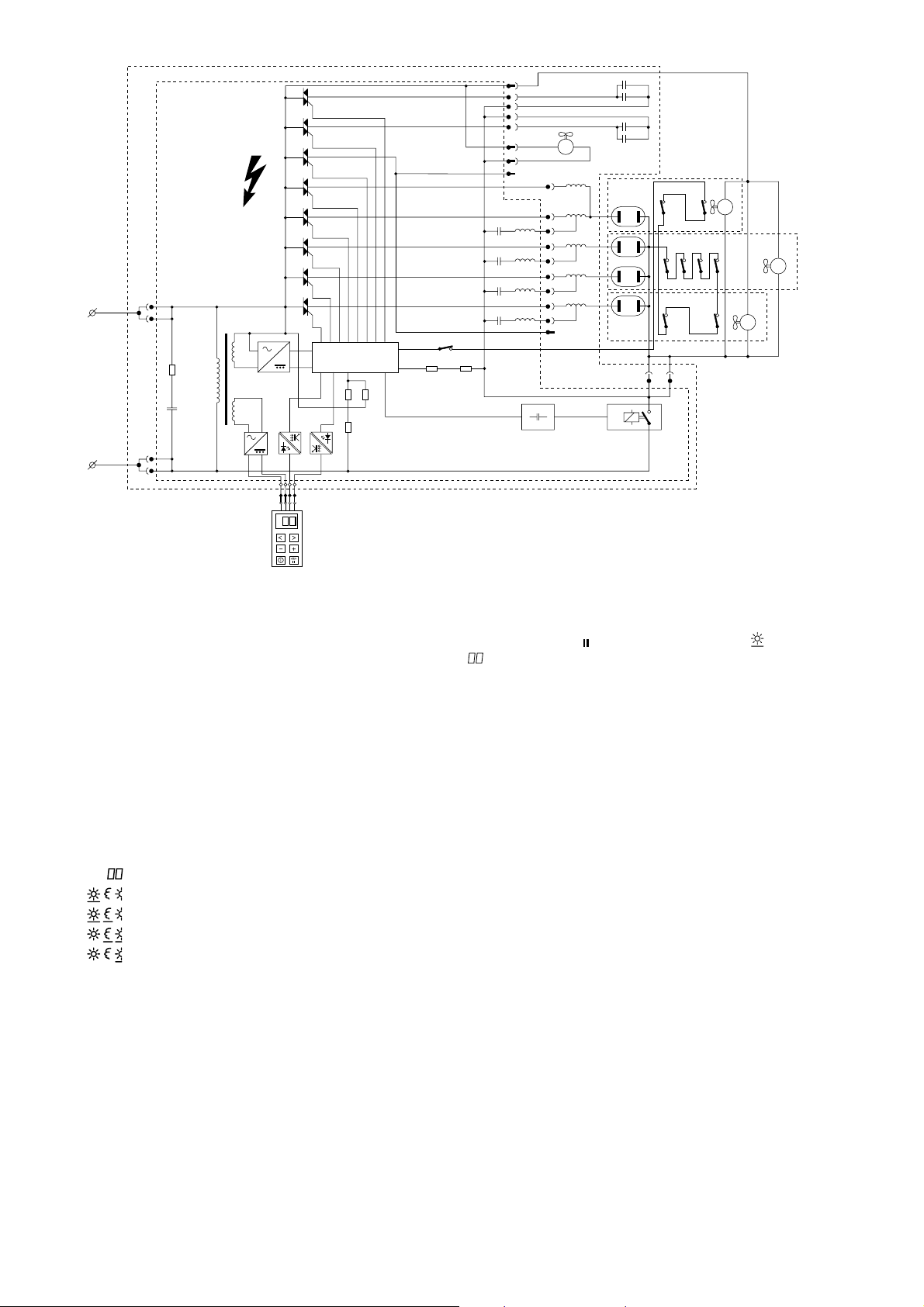
TECHNICAL INFORMATION
Tanning appliance HB971 is equipped with a universal
power PCB.
This means that the specific characteristics of the
appliance have to be programmed in a microcontroller
to determine the way in which various components
are activated.
When the mains plug is inserted into the wall socket,
the display of the remote control will show all functions
available to the user.
Including the various combinations, these functions
are:
time setting
full body tanning
full body + facial tanning
half body + facial tanning
half body tanning
The UV lamps may produce a humming sound just
after start-up. This humming sound will stop as soon
as the lamps burn properly, which is after about
20 seconds. At this point the light intensity clearly
increases.
After pressing the key, the display showing and,
the UV working hours will be shown. After 750
operating hours, an L will automatically appear on the
display to indicate that the HPA lamps need to be
replaced or the tanning time must be slightly
increased.
The clock speed of the µ-controller is derived from the
50 Hz mains frequency.
This frequency is also used to control the 8 triacs that
determine the switch-in point (soft start) of the cos !
capacitors and the HPA lamps.
The fans are switched via the safety relay.
This relay is part of the (one fault condition) timer
circuit.
If the control of the triacs is disturbed due to a fault in
the µ-controller, the UV lamps may not be switched
off.
As the µ-controller also generates a pulsating direct
voltage to power the relay, the relay will be
de-energised in case of a fault, thereby interrupting
the lamp circuit.
Conversely, the appliance will not start if the switch
contacts of the relay are closed at that moment
(sticking contacts).
During the last minute of the session the beeper
produces an intermittent signal to alert the user to the
fact that a new session can be set.
The remote control is galvanically isolated from the
mains, with power supply and control taking place via
a 4-core cable.
The remote control only functions as input/output
terminal.
Page 3

DISASSEMBLY
1. FLOOR PART (item 37)
- Remove the cord holders (item 28) and
detach the cord clamps at the back.
- Remove the covers (item 29 and 39).
The cover on the flex side can only be
removed last.
2. REMOTE CONTROL (item 41)
- Remove the cord holder and pull the
connector loose.
3. WHEEL (item 49)
- Remove the covers (item 29,39).
- Remove the locking plate and the nearest
frame screw.
- Push the shaft out of its clamping.
4. GAS SPRING (item 14)
- Remove the covers (item 29,39).
- Put the appliance in its highest operating
position (to ensure that no pressure is
excerted on the gas spring) and tighten the
ornamental screw (item 26).
- Loosen the 8-core cable so that the cable
can easely slide through the cable duct.
- Remove a retaining ring from the hinge shaft
at A.
- Tilt the appliance carefully so that the
radiation part rests on the floor.
- Support the floor part to remove the
pressure from the hinge shaft.
- Remove the hinge shaft and lower the floor
part onto the floor.
- Remove the 2 bearing bushes.
- Loosen the ornamental screw (item 26),
slide the top part of the stand approx. 20 cm
inwards and tighten the screw again.
- Remove the 2 screws from the upper part of
the stand at B and pull this part loose from
the hinge.
- After the shafts have been removed, the gas
spring can be slid out of the stand.
5. HIGHT ADJUSTMENT (item 27)
- Loosen the lower attachment of the gas
spring in the manner described under 4.
- Remove the cord with its clamping by
pressing the snap clamping on the inside.
- Remove the outer tube.
- Remove the 2 guide blocks and slide the
clamping block from the inner tube.
6. HINGE WITH GAS SPRING (item 12)
- Remove the stand part in the manner
described under 4 and 5.
- Remove the upper ornamental strips from
the hinge part.
- Remove the cover (item 17) from the
radiation part.
- Remove the cover from the connector
compartment.
- Detach the 8-core cable.
- Remove the retaining ring from the locking
shaft at C and push the shaft out of the
stand.
- Remove the hinge part.
7. HPA LAMP (item 23)
- Remove the glass filter from the lamp unit in
question.
The lamp unit will continue to cling to the
upper part.
- Remove the reflector clamps.
- Remove the reflector and take the lamp
from the holder.
NB: When checking or replacing HPA lamps,
pay attention to the following:
a. HPA lamps only start burning when they
have cooled down sufficiently.
b. Never touch a lamp with your fingers.
Clean the lamp with a cloth moistened with
alcohol, if necessary.
c. After assembly the glass filter should be free
from finger prints and dust. Clean the glass
filter with a cloth moistened with alcohol, if
necessary.
8. COVER OUTER SECTION (item 19)
- Remove the cover (item 17) and the cover
of the connector compartment.
- Detach the wires of the outer section.
- Support this section and remove the 3 fixing
screws at D.
9. COVER INNER SECTION (item 1)
- Disassembly of the cover is not advisable,
since the non-visible parts of the pivot can
only be fitted with special tools.
For this reason, the cover is supplied as a
whole with grip plate and wiring.
- Remove the centre glass filter and assemble
it onto the new cover.
- Remove the outer sections (see under 8)
and attach them to the inner section.
- Detach the wiring that runs through the tube
of the stand.
- Remove the upper ornamental strips.
- Remove the retaining ring from the locking
shaft at C and push the shaft out of the
stand.
- Pull the inner section out of the stand.
10. POWER PCB (item 30)
- Pull the mains plug out of the wall socket.
- Remove the cover (item 29, see under .1)
- Replace the power PCB and connect all
connectors.
- Place the cover on the base. The display of
the remote control will now show error code
E06 or E05.
- This indicates that the power PCB still
needs to be programmed (code A08) for use
in the HB971 according to the input in the
table.
The following fault codes have been defined:
E01 - Safety circuit interrupted
This code will appear on the display for
5 seconds, while the beeper produces a
loud beep.
Check whether the lamp units are in the
correct position, whether all fans work
or whether any UV filter is missing,
broken or damaged.
E02 - Safety relay does not work according
to specification
Replace the power module (item 30).
E03 / Fault in microprocessor
E04 - Replace the power module (item 30).
E05 / Application code not programmed
E06 - This only occurs in case of a new
power module supplied by Service.
Program the application code,
beginning at line 1, step 3.
Page 4

01
2
3
45 76891011
1
Open Service Mode
Set Application Code
2
Close Service Mode
3
1 4222 062 94880 housing with grip
2 4822 442 01238 end cover
3 4822 321 11397 flex L/R 5c
4 4822 271 30619 micro switch
5 4822 214 12662 14-tabs pcb
6 4222 062 94800 lamphousing L(facial)
4222 062 94990 lamphousing R
7 4822 252 11236 automatic cutout 120C
8 4822 380 10228 reflector M
9 4822 450 10449 distance indicator
10 4222 062 94790 lamphousing M
11 4822 530 70444 spring washer
12 4222 062 94760 hinge complete
13 4822 321 11396 flex in stand 8c
14 4822 529 10401 gasspring
E5
E6
Press
C02
2x 1x 8x
1x
00
+ 1x + 1x + 1x+ 1x
A00 A08 C02 C00
C00
+ 1x + 1x
1x 2x
26 4222 062 94750 adj. knob
27 4822 401 11732 clamping unit
28 4822 256 10435 flexholder L/R
29 4822 442 01236 cover R.C.-side
30 4222 062 94720 power module
31 4222 062 94860 4-s connector mains
32 4222 062 94870 4-s connector capacitors
33 4222 062 94850 9-s connector ballasts
34 = 5
35 4222 062 94730 fan complete
36 4222 062 95010 pcb frame
37 4822 441 12109 housing floorpart
38 4822 462 11021 orn. prop (4x)
39 4822 442 01235 cover flex-side
40 4822 321 11395 mains flex
15 4822 530 70126 retaining ring
16 4822 401 11733 flex clamping
17 4822 498 10689 grip cover
18 4822 265 11215 tab connector
19 4222 062 94830 cover L(facial)
4222 062 95000 cover R
20 4822 361 11042 fan complete M
4222 062 94840 fan complete L
4222 062 94810 fan complete R
21 4822 325 20102 lampholder
22 4222 062 94820 reflector L(facial)
4822 380 10229 reflector R
23 4822 134 30032 HPA lamp
24 4222 062 94770 orn. strips (2x3)
25 4222 062 94780 orn. caps (4x)
41 4222 062 94710 remote control
42 4822 146 10935 ballast 500W/230V
43 4222 062 94330 ballast 400W/230V
44 4222 062 94740 bar grip
45 4822 528 70519 wheel small
46 4222 062 94890 ballast 100W/230V
47 4222 062 94600 capacitor 50µF/250V
48 4822 265 20234 connecting block mains
49 4822 528 11215 wheel large
Page 5

HB 971/A
17
10
1
D
2
3
4
5
6
7
8
9
18
19
20
21
22
11
12
13
14
23
C
B
24
25
15
16
A
26
27
Page 6

28
38
29
30
31
32
33
34
35
39
40
41
42
43
36
37
44
A
45
46
47
48
49
Page 7

HB 971/A
Page 8

 Loading...