

Philips HB556AB Service Manual
Solarium
HB556/A
HB556/B
Philips Domestic Appliances and Personal Care
Service Manual
TECHNICAL INFORMATION
Input consumption : approx. 1415 W / 230 V / 50 Hz
Lamp : 6x TL Cleo Performance 100 W-S
: 4x TL Cleo Performance 80 W-S
: 1x HP400/H (HB556/A)
: 1x HP400/SH (HB556/B)
Starter : 10x S12
: 1x ZG 4,5D
Ballast : 7x 100 W / 230 V
: 6x 80 W / 230 V
Timer : 1x 30 mins – motor-driven
Radiation area : 174 x 58 cm
Radiation distance : 20 cm
Height adjustment : between 67 – 97 cm
Protecting goggles : HB071 – 4822 690 80123
Output UVX36 meter : > 5.5 mW/cm² at 20 cm (HP400 on)
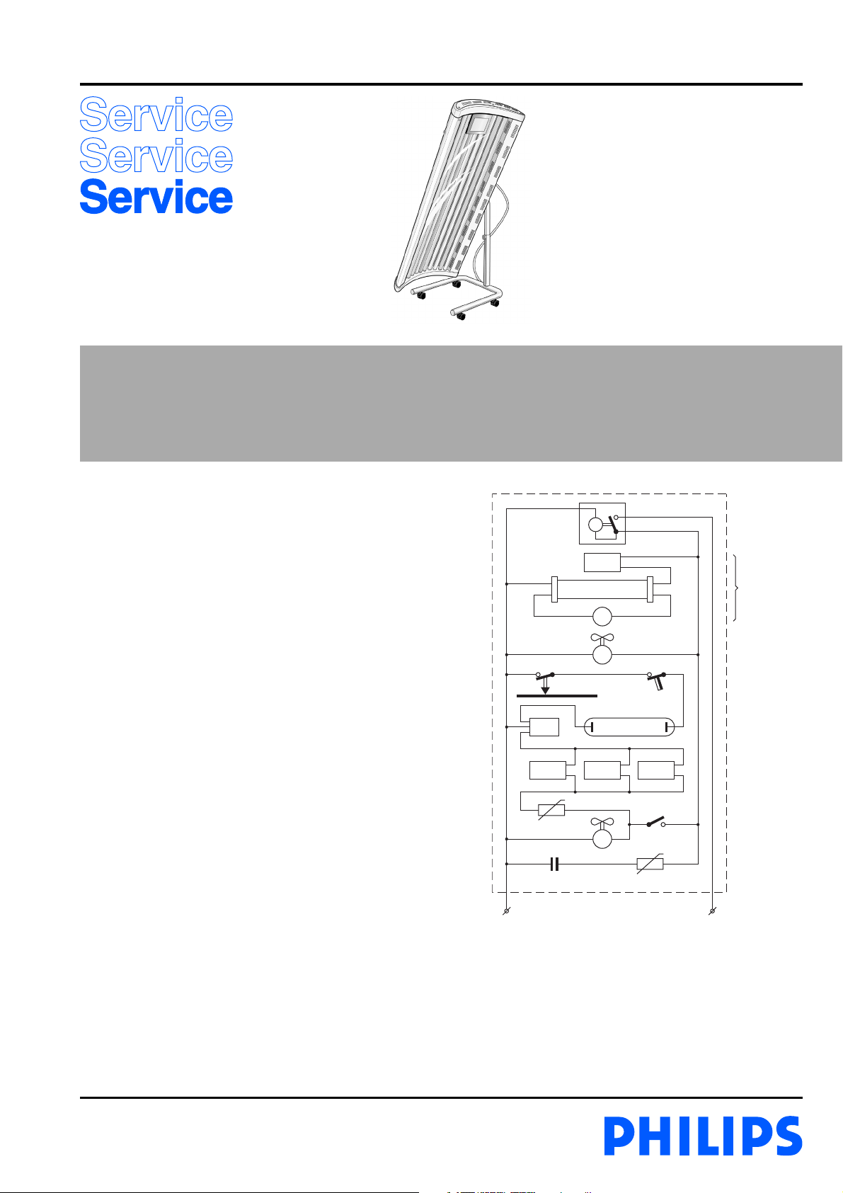
SK1
M
L
La
S
SK3 TCO
S11
L11a
NTC1
C NTC
M1
La11
M2
230 V / 50 Hz
L11cL11b
SK2
6 x
100 W
4 x
80 W
1 x
HPA
260 W
Published by Philips Domestic Appliances and Personal Care Printed in the Netherlands © Copyright reserved Subject to modification
03/02

HINTS FOR REPAIRS
HB556/A HB556/B
- Interchange starters, lamps or ballasts to establish
whether they are defective.
- If they are not defective, check the internal wiring,
especially that connected to the lamp holders.
- The snap-on connections of the wiring can be detached
by means of a paperclip.
- Premature blackening of a tube end points to a defective
starter or a wiring fault.
- A burned NTC resistor or overheated wiring points to a
wiring fault at the connecting block.
Replacement of lamps/starters (items 33, 34 and 11)
Loosen the screws (item 6) and remove the end covers
(item 5).
Pull the acrylic sheet (item 35) out of the appliance.
Now the lamps/starters can be replaced.
Disassembly of gas spring (item 8)
Put the canopy in its highest position.
Fasten ornamental screw (item 7).
Remove the 2 screws (A).
Lift the canopy off the foot together with a second person.
Place the canopy on a soft surface.
The gas spring can now be taken out.
Disassembly of fan (item 13)
Unlock the clamps of the fan cover (item 12).
Loosen the connecting wires and pull out the fan unit
(item 13).
Disassembly of timer (item 20)
Remove the end cover on the side where the timer is
located.
Pull the top cover on this side out of the groove of the side
panel (item 17).
Pull the side panel off the metal frame to create enough
room to remove the timer.
Disassembly of hinge (items 14, 15 and 16)
Unlock the clamps of the hinge cover with a screwdriver.
Loosen the screw (B).
Ask a second person to depress the locks of the bearing
bush (item 16) with two small screwdrivers.
Position yourself on the other side of the appliance and
press the stand with your foot while pulling the canopy
slightly (approx. 5 mm) towards you to deactivate the lock.
Now you and the other person should position yourselves
at opposite ends of the appliance. Lift the canopy from the
stand by pulling at it.
Place the canopy on a soft surface.
Remove the lock spring (item 15)
Tap the bearing bush off the shaft with a plastic hammer.
Disassembly of facial unit (item 24)
Remove the fan, the end covers and the top cover.
Contrary to what is indicated in the exploded view, a
complete refl ector unit with fi lter glass mounted in a metal
frame is supplied as item 24.
2-4
 Loading...