

Philips HB 544-A Service Manual
Service
Service
Service
UV-A Solarium
HB 544/A
Domestic Appliances and Personal Care
Service Manual 4822 729 21763 is
herewith cancelled.
Service Manual
SAP coding 8843 544 99999
PRODUCT INFORMATION
UVA lamps
Input power
Starter
Ballast
Timer
Radiation area
Radiation distance
Height adjustment
Protecting goggles
Output UVX36 meter
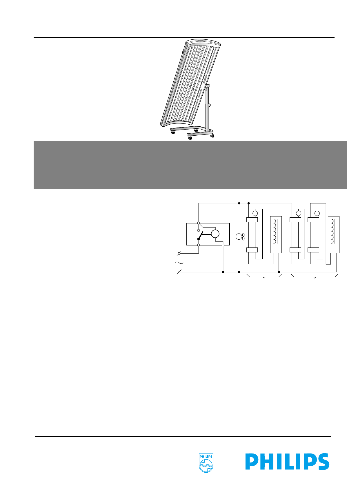
HINTS FOR REPAIRS
-
By interchanging it can be found out whether starters,
lamps or ballasts are defective.
If they are not, the internal wiring is to be checked,
especially that on the tube holders.
-
The snap-on connections of the wiring can be
unlocked with a paper clip.
-
The quick blackening of a tube-end points to a
defective starter or a wiring fault.
-
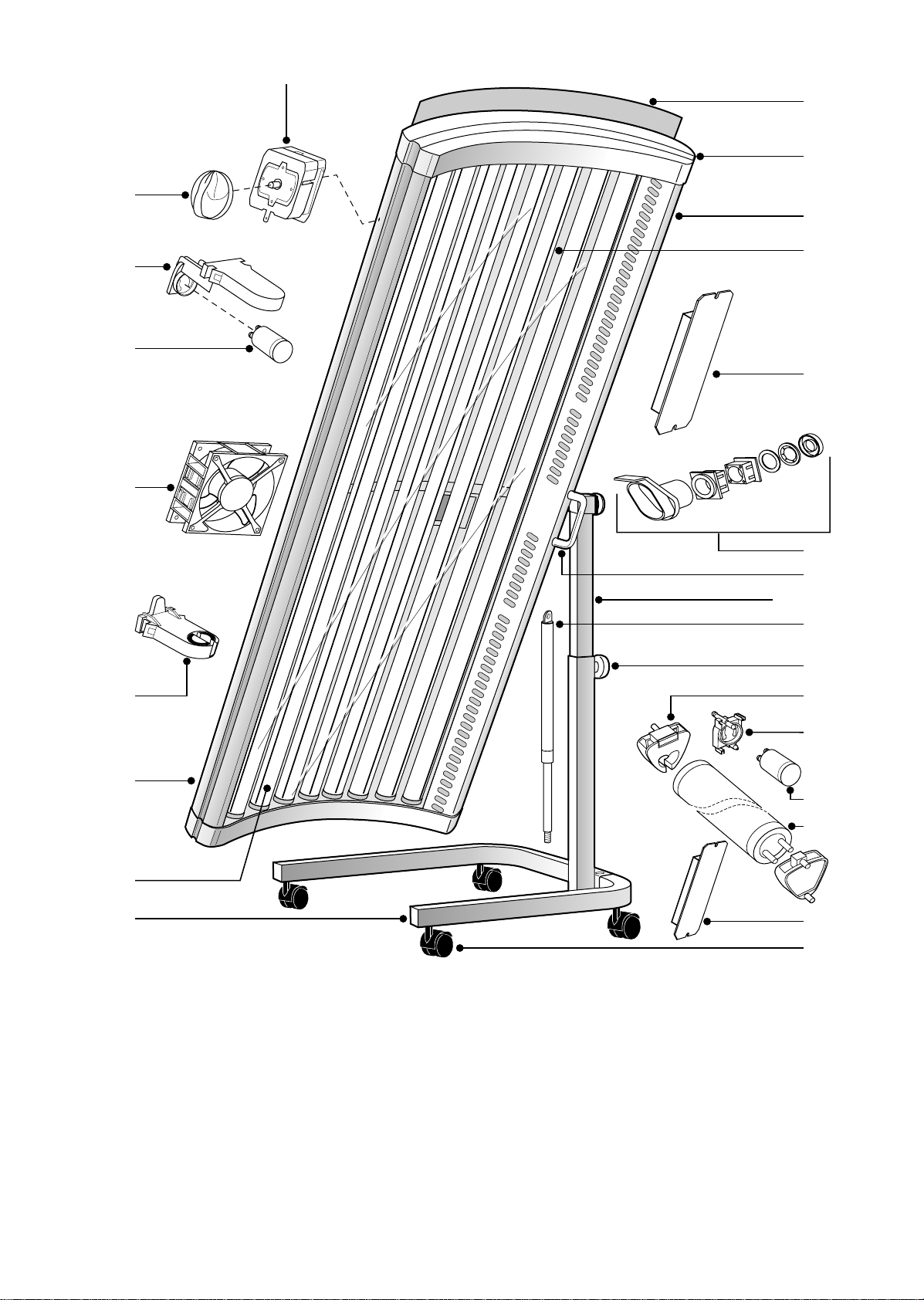
Disassembly of radiation part
Remove end cover (item 11, 2x).
Remove cover (item 10) and acrylic plate (item 13).
For removal of ballast or fan the pop rivets must
be drilled out.
New parts have to be fixed with pop rivets 4.8 mm
or blind-rivetting nuts M3 (no service items).
:
10 x TL100W/Cleo
:
4 x TL 15W/Cleo
:
approx. 1160W
:
10 x S12
:
4 x S2
:
10 x 100W/230V
:
2 x 30W
:
60 mins Eaton
:
170 x 56 cm
:
20 cm
:
between 66-96 cm
:
HB071 - 4822 690 80123
:
>4.6 mW/cm at 20 cm
2
S
a
M
a1 b1
Disassembly of gasspring (item 18)
Put solarium in highest position.
Fasten ornamental screw (item 19)
Now turn the stand and the radiation unit through
so far that the legs of the stand and the radiation
unit rest on the floor.
Remove the nut inside the stand tube.
Remove the ornamental screw and unlock the
plastic guide block.
Separate the inner and outer stand part.
Remove the ornamental prop and the spring clip
at the inner side of the stand and lift the pin out.
The gasspring can be taken out now.
Note: a new gasspring comes with plastic guide
block, spring clip and ornamental prop.
Disassembly of hinge (item 15)
Remove the ornamental prop, spring clip and
plastic ring.
Polish the shaft with abrasive paper to make the
removal of guide blocks easier.
On assembly see to it that the cams of the spring
clip rest in the groove on the shaft.
La
M
L
10 x
S S
2x
Published by Philips Domestic Appliances and Personal Care Printed in The Netherlands Copyright reserved Subject to modification
©
4322 277 00366
00/08
HB 544/A
1
2
3
4
9
10
11
12
13
14
5
6
7
8
1
4822 410 11079
2
4822 255 10255
3
4822 219 80258
4
4822 361 10966
5
4822 255 10254
timer knob
lamp/starter holder
S12 starter
fan 230V
lamp holder
16
9965 000 02280
17
9965 000 02732
18
4822 529 10329
19
4822 502 13999
20
4822 255 10182
15
16
18+17
18
19
20
21
22
23
24
25
handgrip
stand with gasspring
gasspring
orn. screw
lamp holder
6
9965 000 06405 side panel
7
4822 134 30014
8
4822 462 11193
9
4822 349 40068
10
4822 441 11963
11
4822 442 00006
12
9965 000 01865
13
4822 466 10705
14
4822 146 10344
15
4822 520 10789
TL 100W/Cleo
U-shaped foot
timer 60 mins
cover
end cover
side panel with grip
acrylic plate
ballast 230V/100W
bearing set
21
4822 255 10153
22
5322 219 80597
23
4822 134 30026
24
4822 142 60359
25
4822 528 10924
4822 690 80147
starter holder
S2 starter
TL 15W/Cleo
ballast 230V/30W
swivel wheel
HB072 prot. goggles
 Loading...