

Page 1

Provapor elance
GC 6005
Service
Information
!
Philips Domestic Appliances and Personal Care
Service Manual
SAP coding GC 6005
PRODUCT INFORMATION
Feataures : optinox sole plate
boiler capacity 1 litre
length steam hose 1,9 metre
length cord set 1,9 metre
maximum steam output 80 gr/min
steam ready indicator
Voltage : 220-240 Volt
Frequency : 50-60 Hz
Power consumptium : Boiler : 1200 Watt
Pressure : 3,5 bar
Iron : 800 Watt
Product meets the requirements regarding interference
suppression on radio and television.
- After the product has been repaired, it should function
properly and has to meet the safety requirements as laid
down offi cially established at this moment.
Published by Philips Domestic Appliances and Personal Care Printed in the Netherlands © Copyright reserved Subject to modification
4322 277 00601
01/04
Page 2
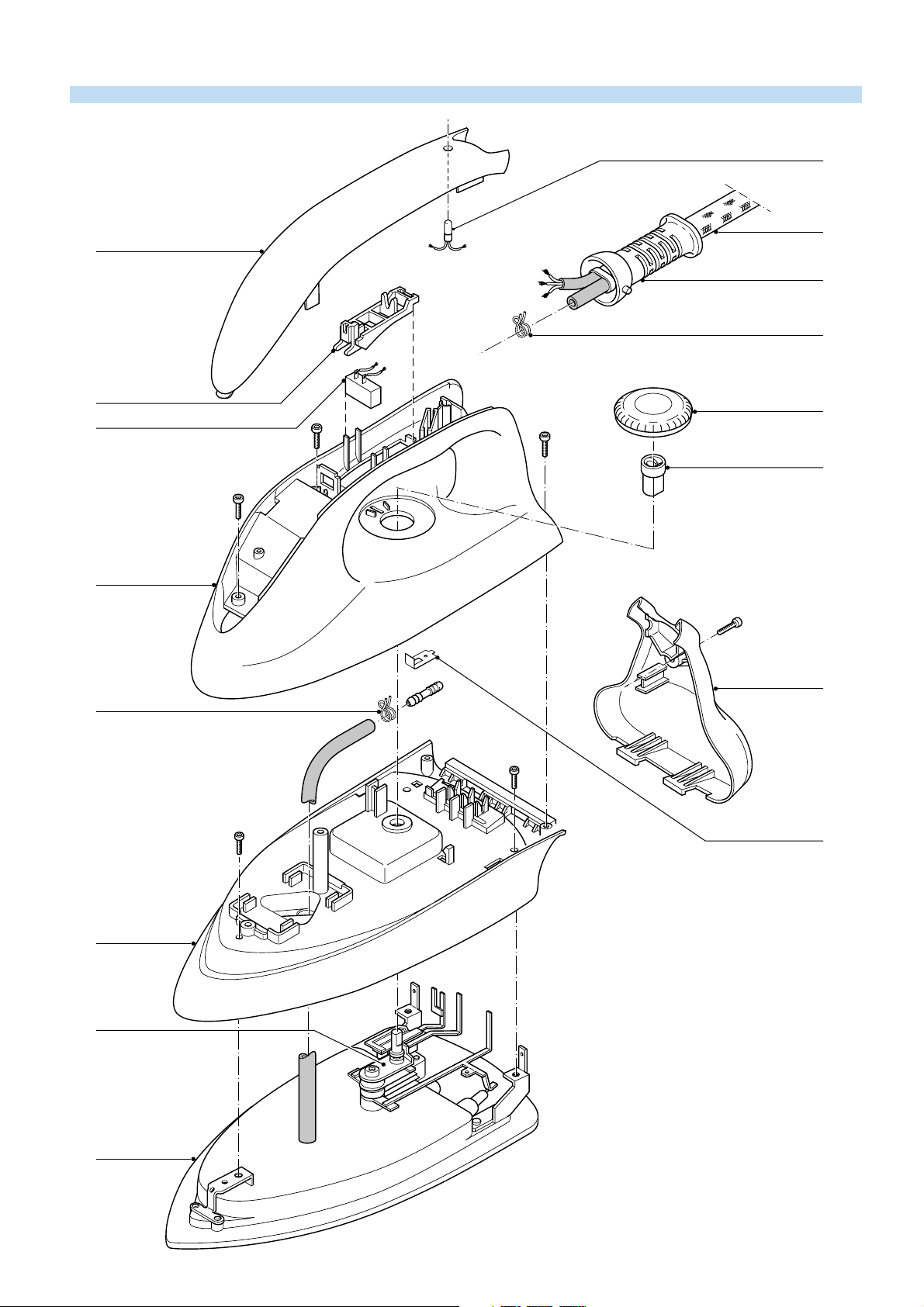
EXPLODED VIEW IRON
1
10
2
11
14
14
3
4
2
B
B
5
B
6
A
12
C
C
7
13
8
9
DAP1560
Page 3

PARTS LIST IRON
Pos Service Nummer Description
Iron inlay
Intermediate cable + microswitch
Electro valve trigger
Thermostat dial
Thermostat joint
Iron handle
Rattle
Iron skirt
Soleplate unit
Iron lamp
Ball swivel
Iron back part
Iron thermostat
Spring clamp
10
11
12
13
14
1
2
3
4
5
6
7
8
9
9965 000 08140
9965 000 08141
9965 000 08184
9965 000 08185
9965 000 01682
9965 000 08186
4822 492 71445
9965 000 08187
9965 000 08188
9965 000 01686
9965 000 01687
9965 000 08189
9965 000 01690
4822 492 71001
STAND IRON
Main
switch
Steam
ready
Boiler
thermostat
Boiler
heating
element
Cut
out
p
Electro-
valve
Steamswitch
Thermostat
Page 4

DISASSEMBLY ADVISE IRON
BACK PLATE 12
remove SCREW A
INLAY 1
remove LAMP 10
remove MICRO SWITCH 2
HANDLE 6
remove THERM. DIAL 4
remove SCREW B (4x)
unlock HANDLE carefully
SKIRT 8
remove ELECTRICAL
WIRES
remove EXTENSION
PIECE 5
remove SPRING CLAMP
FROM STEAM HOSE
remove SCREW C (3x)
Bend back the contact points
THERMOSTAT 13
ONLY
cut CONDUCTOR A
at location P
remove SCREW D
P
Q
B
A
ASSEMBLY
REQUIREMENTS
THERMOSTAT 2
Instead of metal conductor A,
the new thermostat has a wire
with AMP clamp.
After fi xing screw D, connect
the AMP clamp to tag Q.
After assembling SKIRT 8
ALWAYS turn conductor B
through 180 degrees.
D
ADJUSTMENT AND CONTROLS
Thermostat 13
Thermostat ( 13 ) supplied as a spare part or fi tted to
the sole plate ( 9 ) has already been a djusted by the
supplier and secured by glue.
To avoid disfunction of the iron , NEVER readjust the
thermostat.
NOTE :
For opening you need a Torx screwdriver 362 TR
T20 x 100.
Page 5

EXPLODED VIEW STAND
24
26
37
23
22
E
31
27
25
28
30
27
33
32
36
34
35
29
DAP1571
Page 6

PARTS LIST + DISASSEMBLY ADVICE STAND
Pos Service Nummer
22
23
24
25
26
27
28
29
30
31
32
33
34
35
36
9965 000 08193
9965 000 08194
9965 000 08195
9965 000 01782
9965 000 08252
4822 462 71999
9965 000 08240
9965 000 08201
9965 000 08202
9965 000 01790
9965 000 08203
4822 218 11561
9965 000 08241
9965 000 01900
9965 000 01902
Description
Tray rubber foot for fi xation
Complete tray
Safety cap for boiler
Filling hole gasket for alu boiler
Superior stand printed
Boiler rubber feet
Complete boiler
Locket insert
Inferior stand
Filter
Main switch
Electrovalve
Steam dial
Sream regulator
Steam ready light
37 9965 000 08246 Funnel
ADJUSTMENT AND CONTROLS
– To avoid leakage of the sealings and damage to
the components in and on the boiler, NEVER clean
the boiler with vinegar, a descaling agent or other
chemicals.
OPEN THE STAND
pressure fi xation rubber through
the tray
E
remove SCREW E (3 x)
E
E
– The boiler doesn’t contain serviceable parts.
Never disassemble the boiler body and /or
components on and in the boiler.
– ALWAYS REPLACE THE BOILER ( 28 ) WHEN:
the mechanical safety valve ( 24 ) has been
*
activated.
the boiler thermostat or hand - resettable safety
*
thermostat are open, because the boiler has
been subjected to too high temperatures.
the electrovalve ( 33 ) fails or the sieve is soiled
*
with scale.
– After the product has been repaired, it should
function properly and has to meet the safety
requirements as laid down and offi cially established
at this moment.
remove LOCKED INSERT 29
NOTE:
OPEN NOW THE STAND.
DON’T WORRY IF THE SNAPS AT THE SIDE WILL BE
BROKEN.
THEY ARE ONLY FOR THE ASSEMBLY.
THE STAND REMAINS CLOSE WITHOUT THESE SNAPS.
 Loading...