

Philips FWV-135 Service Manual
Version 1.0
FWV135
© 3141 785 30750
Service Manual
MP3 VCD Mini System
all versions
Published by LX 0611 Service Audio Printed in The Netherlands Subject to modification
©
Copyright 2006 Philips Consumer Electronics B.V. Eindhoven, The Netherlands
All rights reserved. No part of this publication may be reproduced, stored in a retrieval
system or transmitted, in any form or by any means, electronic, mechanical, photocopying,
or otherwise without the prior permission of Philips.
TABLE OF CONTENTS
Handling chip components ............................................................1-1
Information about lead-free soldering............................................1-2
Technical specification...................................................................2-1
Service tools..................................................................................2-1
Service measurement setup..........................................................2-2
Connections and controls......................................................3-1...3-2
Maintenance and troubleshooting .................................................3-3
Disassembly diagram............................................................4-1...4-2
Set block diagram..........................................................................5-1
Set wiring diagram.........................................................................5-2
TUNER BOARD
circuit diagram ..........................................................................6-1
layout diagram...................................................................6-2 6-3
AUDIO BOARD
circuit diagram ..........................................................................7-1
layout diagram..........................................................................7-2
CONTROL BOARD
circuit diagram ..........................................................................8-1
layout diagram..........................................................................8-2
CASSETTE BOARD
circuit diagram ..........................................................................9-1
layout diagram..........................................................................9-2
VCD BOARD
circuit diagram ........................................................................10-1
layout diagram........................................................................10-2
Exploded view diagram................................................................11-1
Mechanical partslist.....................................................................11-2
Electrical partslist...............................................................12-1...12-4
VIDEO CD
CLASS 1
LASER PRODUCT
1 - 1
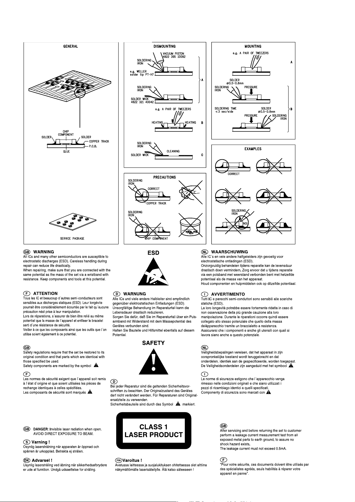
HANDLING CHIP COMPONENTS

1 - 2
INFORMATION ABOUT LEAD-FREE SOLDERING
Philips CE is producing lead-free sets from 1.1.2005 onwards.
IDENTIFICATION:
Regardless of special logo (not always indicated) one must treat all sets from 1 Jan 2005 onwards, according next rules:
Example S/N:
• Use only lead-free solder alloy Philips SAC305 with order code 0622 149 00106. If lead-free solder-paste is required, please contact
the manufacturer of your solder-equipment. In general use of solder-paste within workshops should be avoided because paste is not
easy to store and to handle.
• Use only adequate solder tools applicable for lead-free solder alloy. The solder tool must be able
• Adjust your solder tool so that a temperature around
• Mix of lead-free solder alloy / parts with leaded solder alloy / parts is possible but PHILIPS recommends strongly to avoid mixed
• Use only original spare-parts listed in the Service-Manuals. Not listed standard-material (commodities) has to be purchased at
• Special information for BGA-ICs:
• For sets produced before 1.1.2005 (except products of 2004), containing leaded solder-alloy and components, all needed spare-parts
• On our website www.atyourservice.ce.Philips.com
o To reach at least a solder-temperature of 40
o To stabilize the adjusted temperature at the solder-tip
o To exchange solder-tips for different applications.
solder-joint should not exceed ~ 4 sec. Avoid temperatures above 400 otherwise wear-out of tips will rise drastically and flux-fluid
will be destroyed. To avoid wear-out of tips switch off un-used equipment, or reduce heat.
solder alloy types (leaded and lead-free).
If one cannot avoid or does not know whether product is lead-free, clean carefully the solder-joint from old solder alloy and re-solder
with new solder alloy (SAC305).
external companies.
- always use the 12nc-recognizable soldering temperature profile of the specific BGA (for de-soldering always use the lead-free
temperature profile, in case of doubt)
- lead free BGA-ICs will be delivered in so-called 'dry-packaging' (sealed pack including a silica gel pack) to protect the IC against
moisture. After opening, dependent of MSL-level seen on indicator-label in the bag, the BGA-IC possibly still has to be baked dry.
(MSL=Moisture Sensitivity Level). This will be communicated via AYS-website.
Do not re-use BGAs at all.
will be available till the end of the service-period. For repair of such sets nothing changes.
BGA-de-/soldering (+ baking instructions)
∗
Heating-profiles of BGAs and other ICs used in Philips-sets
∗
Bottom line of typeplate gives a 14-digit S/N. Digit 5&6 is the year, digit 7&8 is the week number,
so in this case 2005 wk12
So from 0501 onwards = from 1 Jan 2005 onwards
Im portant note
you avoid mixing solder-alloys ( leaded/ lead -free). So best to always use SAC305 and the
higher temperatures belong to this.
Due to lead-free technology some rules have to be respected by the workshop during a repair:
: In fact also product s of year 2004 must be treated in this way as long as
− is reached and stabilized at the solder joint. Heating-time of the
you find more information to:
For additional questions please contact your local repair-helpdesk.
You will find this and more technical information within the "magazine", chapter "workshop news".
SERVICE INSTRUCTION
Safety regulations require that after a repair, the set must be returned in its original condition. Pay in particular attention to
the following points:
· Route the wire trees correctly and fix them with the
mounted cable clamps.
· Check the insulation of the AC Power lead for external
damage.
· Check the strain relief of the AC Power cord for proper
function.
· Check the electrical DC resistance between the AC Power
Plug and the secondary side (only for sets which have a AC
Power isolated power supply):
1. Unplug the AC Power cord and connect a wire
between the two pins of the AC Power plug.
2. Set the AC Power switch to the "on" position (keep the
AC Power cord unplugged!).
3. Measure the resistance value between the pins of the
AC Power plug and the metal shielding of the tuner or
the aerial connection on the set. The reading should be
larger than 4.5 Mohm (For U.S. it should be between
4.2 Mohm and 12 Mohm).
4. Switch "off" the set, and remove the wire between the
two pins of the AC Power plug.
• Check the cabinet for defects, to avoid touching of any
inner parts by the customer.

2 - 1
TECHNICAL SPECIFICATIONS
GENERAL
Mains voltage
Mains frequency
Battery
Power consumption
Dimension (W x H x D)
Weight
(with/without speaker)
remote
normal 45 W
Standby
:
120/230V
-/98
:
-/98
50/60 Hz
:
R06 (AA)
<
:
:< 7 W
: 265 x 300 x 254 mm
: 6.5 / 4 Kg
AMPLIFIER
Output power : 2 x 10 W
Speaker impedance
Frequency response
Signal to Noise ratio
2 x 6 ohm
:
:
63 Hz - 16 kHz (±3dB)
:
> 62 dBA
TUNER - FM SECTION
Tuning range : 87.5 - 108 MHz
IF frequency
Sensitivity
Selectivity
IF Rejection
Image Rejection
Distortion
Tuning Grid
300kHz : < 4 9 dB
: 10.7 MHz ± 0.02 MHz
:< 22 dBf at 26 dB
:> 40 dB
:> 18dB
:< 6 %
:
50K Hz
TUNER - AM SECTION
Tuning range :
Tuning Grid
IF frequency
Sensitivity
Selectivity S9/300kHz
IF rejection
Distortion
Image rejection
522 - 1611 kHz
:
9K Hz
:
455 kHz ± 3 kHz
≤ 4 mV/m 26 dB
:
:
:> 16 dB
:
:> 24 dB
:< 7%
:
:> 28 dB
AUDIO CASSETTE RECORDER
Number of tracks : 2 stereo
Tape speed : 4.7 cm/sec +3/-3%
Wow & flutter : < 0.4 % DIN
Fast wind/rewind C60 : 160 sec.
Frequency response P/B : 80 - 12500 Hz
S/N ratio : 48 dBA
VIDEO PERFORMANCE
Number of progarmmable track 20
Channel sepatation 1 kHz : ≥ 25 dB
S/N ratio
Frequency response : 63 -16000Hz
MPEG1 : VCD version 2.0
MPEG1 Layer 3 : MPEG AUDIO
MP3-CD bit rate : 32 - 256 kbps
:
: ≥ 62 dBA
SERVICE TOOLS
Audio signal disc SBC 429.......................................................................4822 397 30184
Playability test disc SBC 444
Test disc 5 (disc without errors ) +
Test disc 5A (disc with dropout errors, black spots and fingerprints)
SBC 426/426A.....................................................................4822 397 30096
Burn in test disc (65 min. 1kHz signal at -30 dB level without “pause”)
...................................................................4822 397 30245
.....4822 397 30155
AVAILABLE ESD PROTECTION EQUIPMENT
anti-static table mat
anti-static wristband
connection box (3 press stud connections, 1MΩ) 4822 320 11307
extendible cable (2m, 2MΩ, to connect wristband to connection box) 4822 320 11305
connecting cable (3m, 2MΩ, to connect table mat to connection box) 4822 320 11306
earth cable (1MΩ, to connect any product to mat or to connection box) 4822 320 11308
KIT ESD3 (combining all 6 prior products - small table mat) 4822 310 10671
wristband tester 4822 344 13999
large 1200x650x1.25mm 4822 466 10953
small 600x650x1.25m 4822 466 10958
4822 395 10223

2 - 2
S
ERVICE MEASUREMENT
Tuner SW
RF Generator
e.g. PM5326
Aerial replacement
DUT
Capacitor
Ri=50Ω
R=50Ω
Bandpass
250Hz-15kHz
e.g. 7122 707 48001
LF Voltmeter
e.g. PM2534
S/N and distortion meter
e.g. Sound Technology ST1700B
To avoid atmospheric interference all AM-measurements have to be carried out in a Faraday«s cage.
Use a bandpass filter (or at least a high pass filter with 250Hz) to eliminate hum (50Hz, 100Hz).
Tuner AM (MW,LW)
RF Generator
e.g. PM5326
Ri=50Ω
DUT
Frame aerial
e.g. 7122 707 89001
Bandpass
250Hz-15kHz
e.g. 7122 707 48001
LF Voltmeter
e.g. PM2534
S/N and distortion meter
e.g. Sound Technology ST1700B
To avoid atmospheric interference all AM-measurements have to be carried out in a Faraday«s cage.
CD
Use Audio Signal Disc SBC429 4822 397 30184 (replaces test disc 3)
L.P.F. = 13
th
order filter 4822 395 30204
DUT
L
R
Low pass filter 22kHz
LEVEL METER
e.g. Sennheiser UPM550
with FF-filter
S/N and distortion meter
e.g. Sound Technology ST1700B
3 - 1
CONNECTION AND CONTROLS
1
VCD/CD TUNER TAPE AUX
3
(
ECHO
°
%
KEY PROG
‡
#
^
&
ALBUM ALBUM
9
8$flfi›
)@¡™£
ZOOM
A-B
PAL/
NTSC
DBB DSC
PBC RETURN DIGEST
DISPLAY
REPEAT SHUFFLE REPEAT
≤
∞
GOTO RESUME SLOW AUDIO/VOCAL
OSD
‹¤⁄
§
CLOCK SET TIMER SLEEP MUTE
≥
º
•
ª
*
PUSH
!
@
#
$
%&^
2
1
3
4
597
6
8
0

3 - 2
CONNECTION AND CONTROLS
p
y
(
)
Controls
2;
for example).
vocal range.
‡ KEY
– Changes the VCD key tone level to suit your
DIGEST
– Scans through a VCD or its specific track.
≤
inserting the microphone.
° ECHO
– Adjusts the VCD echo level for Karaoke after
or switches between mono or stereo mode
during audio disc playback.
suond, or selects a luanguage in a billingual VCD.
∞ AUDIO/VOCAL
– Fades out the original vocal from a Karaoke VCD
– Selects channel left / channel right / stereo
§ SLOW
–Watches the VCD at a slower speed.
• SLEEP
≥ MUTE
– Mutes or restores sound.
RESUME
have stopped
– Activates/ deactivates or sets sleep timer
– Sets and activates the wake-up timer
ª TIMER
⁄
– Enters clock setting mode
º CLOCK SET
– Continues VCD playback again from where you
– starts playback at any chosen time on the disc
¤ GOTO
(for CD/VCD operation only and PBC mode is
off).‹DISPLAY (OSD)
– For VCDs: displays the disc information.
› PBC (Playback Control)
only)
– Switches on or off the PBC mode (for VCD 2.0
fi REPEAT
Notes for remote control:
– First, select the source you wish to
control by pressing one of the source select
keys on the remote control (VCD/ CD or
TUNER, for example).
– Then select the desired function ( ,
– Repeats a track / CD program / entire disc.
– Plays tracks in a random order.
fl SHUFFLE
S T
9
compartment.
;
.................................Stops the tape; opens the tape
STOP•OPEN /0
PAUSE ...........Interrupts recording or playback.
! REMOTE SENSOR
Controls on the system and
remote control
STANDBY ON y
1
Controls (main set’s illustration on page 3&4)
– Switches the system on or to standby mode.
(Digital Sound Control)
characteristics: POP/ JAZZ/ ROCK/ OPTIMAL.
for VCD/CD/MP3-CD......Programs disc tracks.
for Tuner............. Programs preset radio stations.
– Infrared sensor for remote control.
@ DSC
– (Digital Sound Control) Selects sound
# PROGRAM (PROG)
– Views the current status of the system.
– Selects VCD/CD, TUNER, T APE or AUX.
– Enters clock setting mode.
2 Display screen
3 Source mode
– Sets and activates wake-up timer.
4 CLOCK•TIMER
2;
for Disc.................Starts or interrupts playback.
$ DBB (Dynamic Bass Boost)
– Enhances the bass
% VOL (VOL+/-)
– Increases or decreases the volume.
^ PLAY•PAUSE
& STOP 9
1
/ / SEARCH
mono sound in FM band.
5 MIC V OL
–for Tuner..............Switches between stereo and
– Adjsuts the mixing level for Karaoke.
6 STEREO•MONO
7 MIC IN
– Connects a microphone.
8 ALBUM-/+ 1
clears a program.
0
for VCD/CD/MP3-CD......Stops playback or to
* PUSH
– Opens or closes the disc tray.
( DIGIT 0 – 9
–for CD/VCD/MP3-CD - Select a track number.
1
/ SEARCH buttons only)
(The system’s ALBUM-/+ 1/
(ALBUM 3/4)
for MP3-CD...... Selects previous/next album.
for Audio CD...... Fast reverse/forward the disc.
for VCD.................Fast reverse/forward the disc.
for Tuner...............Tunes to a radio station (The
(numbers consisting more than 2 figures must be
keyed in within 2 seconds)
) PAL/NTSC
– For Disc.......Press and hold to select PAL or
NTSC for clear disc viewing on TV
screen.
1
system’s ALBUM-/+ 1/ /
SEARCH buttons only)
™
¡
for Disc...................Selects a desired track
9 TITLE-/+ / / PRESET (4 / ¢)
– Adjusts the hours for the clock/timer functions.
ZOOM
repeatedly (REPEAT A - B is not possible for
MP3-CD).
¡ REPEAT A - B
– Plays a certain scene or passage of a CD/VCD
(The remote’s 4 / ¢
buttons only)
™
– For Disc................Enlarges a picture or active
image on TV screen.
6
•
5
for VCD.................Fast reverse/forward the disc.
for Tuner..................Selects a preset radio station.
RECORD ....Starts recording.
PLAY 2 ............ Starts playback.
REW / F. FWD
– Adjusts the minutes for the clock/timer functions.
0 Tape deck operations
with PBC on for VCD with PBC
ack
la
VCD
£ RETURN
– Returns to the previous MENU level during
................................... Fast rewinds/ winds the tape.

3 - 3
MAINTENANCE AND TROUBLESHOOTING
Solution
Troubleshooting
If the signal is too weak, adjust the antenna or
connect an external antenna for better
reception.
Increase the distance between the Mini HiFi
System and your TV or VCR.
Clean deck parts, see “Maintenance”.
Use only normal (IEC I) tape for recording.
Remove and reconnect the AC power plug and
switch on the system again.
Adjust the volume.
Check that the speakers are connected correctly.
Check if the stripped speaker wire is clamped.
2;
Check the speaker connections and location.
Select the source (CD or TUNER, for example)
before pressing the function button ( , 4 /
¢ ).
Reduce the distance between the remote
control and the system.
Insert the battery with its polarities (+/– signs)
aligned as indicated.
Replace the battery.
Point the remote control directly toward
REMOTE SENSOR sensor on the front of the
system.
Set the clock correctly.
If a recording is in progress, stop the recording.
Power has been interrupted or the power cord
has been disconnected. Reset the clock/timer.
Problem
A, the capstan(s) B, and
Cleaning the Heads and the Tape Paths
clean the heads
To ensure good recording and playback quality,
Radio reception is poor.
pressure roller(s) C after every 50 hours of
tape operation.
Caution: Do not rotate the heads during
cleaning.
Use a cotton swab slightly moistened with
Recording or playback cannot be made.
cleaning fluid or alcohol.
cleaning tape once.
You can also clean the heads by playing a
The system does not react when buttons
are pressed.
Sound cannot be heard or is of poor
quality.
A A B C
Demagnetising the heads
Use a demagnetising tape available at your
dealer.
The left and right sound outputs are
reversed.
The remote control does not function
properly.
Troubleshooting
The wake-up timer is not working.
Solution
Insert a disc.
The Clock/Timer setting is erased.
Check if the disc is inserted upside down.
Wait until the moisture condensation at the lens
has cleared.
Replace or clean the disc, see “Maintenance”.
Use a finalised CD-RW or CD-R.
Connect the cable betwen the system and TV.
Change the system to the respective PAL or
NTSC setting.
Cleaning the Cabinet
detergent solution. Do not use a solution
containing alcohol, spirits, ammonia or abrasives.
Cleaning Discs
Maintenance
Use a soft cloth slightly moistened with a mild
clean it with a cleaning cloth.
Wipe the disc from the centre
out.
benzene, thinner, commercially
available cleaners, or antistatic spray intended for
analogue records.
When a disc becomes dirty,
Do not use solvents such as
Cleaning the disc lens
accumulate at the disc lens. To ensure good
playback quality, clean the disc lens with Philips
CD Lens Cleaner or any commercially available
cleaner. Follow the instructions supplied with
cleaner.
After prolonged use, dirt or dust may
WARNING
Under no circumstances should you try to repair the system yourself, as this will
invalidate the warranty. Do not open the system as there is a risk of electric shock.
If a fault occurs, first check the points listed below before taking the system for repair. If
you are unable to remedy a problem by following these hints, consult your dealer or
Philips for help.
Problem
“NO DISC” is displayed.
No picture on TV screen.
No colour on TV.

A Remove the Back Cabinet :
A1 Remove screws M3x8 - 7pcs
A2 Remove screws M3x24 - 5pcs
D Remove the Audio board :
D Remove screws M3x8 - 2pcs
E Remove the VFD and Mic Jack board :
F Remove the Recording board :
B Remove the VCD Loader :
E1 Remove screws M3 x10 - 3pcs
E2 Remove screws M3x8 - 3pcs
C Remove the VCD Board and Tuner board :
C1 Remove screws TP2.6x10 - 4pcs
C2 Remove screws M3x8 - 2pcs
A1
A2
B
C1 C2
D
E1
E2
F
B Remove screws M3 x12 - 2pcs
F Remove screws M3 x10 - 3pcs
DISASSEMBLY DIAGRAM
4 - 14 - 1
 Loading...