

Page 1
black film width 210 mm
FW 358C Mini HiFi System
Untitled-26 6/15/00, 4:51 PM1
Page 2
English
Important notes for users in the U.K.
Mains plug
Français
This apparatus is fitted with an approved 13 Amp plug. To change a fuse in this
type of plug proceed as follows:
1 Remove fuse cover and fuse.
2 Fix new fuse which should be a BS1362 5 Amp, A.S.T.A. or BSI approved type.
Español
3 Refit the fuse cover.
If the fitted plug is not suitable for your socket outlets, it should be cut off and an
appropriate plug fitted in its place.
Deutsch
If the mains plug contains a fuse, this should have a value of 5 Amp. If a plug
without a fuse is used, the fuse at the distribution board should not be greater
Nederlands
than 5 Amp.
Note: The severed plug must be disposed of to avoid a possible shock hazard
should it be inserted into a 13 Amp socket elsewhere.
Italiano
How to connect a plug
The wires in the mains lead are coloured with the following code: blue = neutral
(N), brown = live (L).
Svenska
As these colours may not correspond with the colour markings identifying the
terminals in your plug, proceed as follows:
• Connect the blue wire to the terminal marked N or coloured black.
Dansk
• Connect the brown wire to the terminal marked L or coloured red.
• Do not connect either wire to the earth terminal in the plug, marked E (or e) or
Suomi
Português
∂ППЛУИО¿
coloured green (or green and yellow).
Before replacing the plug cover, make certain that the cord grip is clamped over
the sheath of the lead - not simply over the two wires.
Copyright in the U.K.
Recording and playback of material may require consent. See Copyright Act 1956
and The Performer’s Protection Acts 1958 to 1972.
Italia
Dichiarazione di conformita’
Si dichiara che l’apparecchio FW358C Philips
risponde alle prescrizioni dell’art. 2, comma 1
del D.M. 28 Agosto 1995
n. 548.
Fatto a Eindhoven , il 27/2/1998
Philips Sound & Vision
5616 JB Eindhoven, The Netherlands.
Philips, Glaslaan 2, SFF 10
Norge
Typeskilt finnes på apparatens underside.
Observer:
Den innebygde netdelen er derfor ikke frakoplet
nettet så lenge apparatet er tilsluttet
nettkontakten.
For å redusere faren for brann eller elektrisk
støt, skal apparatet ikke utsettes for regn eller
fuktighet.
Nettbryteren er sekundert innkoplet.
2
Untitled-26 6/15/00, 4:51 PM2
3139 116 17941
Page 3
INDEX
CLASS 1
LASER PRODUCT
English .....................................5
Français .................................25
Español ..................................47
Deutsch..................................69
Nederlands............................91
Italiano.................................113
Svenska ...............................135
Dansk ...................................157
Suomi ...................................179
Português ............................199
∂ППЛУИО¿
............................ 221
English
Français
Español
Deutsch
Nederlands
Italiano
Svenska
Dansk
Suomi
Português
∂ППЛУИО¿
Untitled-26 6/15/00, 4:51 PM3
3
3139 116 17941
Page 4

English
4
Untitled-26 6/15/00, 4:51 PM4
3139 116 17942
Page 5
CONTENTS GENERAL INFORMATION SAFETY INFORMATION
General Information ..................................................5
Safety Information .....................................................5
Preparation ........................................................... 6 - 7
Controls .................................................................8 - 9
Operating The System .................................... 10 - 11
CD .......................................................................12 - 14
Tuner .................................................................. 15 - 17
Tape..................................................................... 18- 19
Aux .............................................................................19
Recording............................................................ 20-21
Clock ..........................................................................21
Timer ..........................................................................22
Maintenance ............................................................23
Specifications ..........................................................23
Troubleshooting....................................................... 24
General Information
• The type plate (which contains the serial
number) is located at the rear of the system.
• Recording is permissible if copyright or other
rights of third parties are not infringed.
• This product complies with the radio
interference requirements of the European
Community.
Environmental Information
All unnecessary packaging material has been omitted.
We have done our utmost to make the packaging easily
separable into three mono-materials: cardboard (box),
polystyrene foam (buffer) and polythene (bags, protective
foam sheet).
Your system consists of materials which can be recycled
and reused if disassembled by a specialized company.
Please observe the local regulations regarding the
disposal of packaging materials, exhausted batteries and
old equipment.
Accessories
– Remote control
– Batteries (2 x AAA size) for remote control
– AM loop antenna
– FM antenna wire
– AC power cord
– 1 pair of surround speakers
(Supplied)
Safety Information
• Before operating the system, check that the operating
voltage indicated on the typeplate (or the voltage
indication beside the voltage selector) of your system
is identical with the voltage of your local power
supply. If not, please consult your dealer. The type
plate is located at the rear of your system.
• When the system is switched on, do not move it
around.
• Place the system on a solid base (e.g. a cabinet).
• Place the system in a location with adequate
ventilation to prevent internal heat build-up in your
system.
• Do not expose the system to excessive moisture, rain,
sand or heat sources.
• Under no circumstances should you repair the system
yourself, as this will invalidate the warranty!
• If the system is brought directly from a cold to a warm
location, or is placed in a very damp room, moisture
may condense on the lens of the CD unit inside the
system. Should this occur, the CD player will not
operate normally. Leave the power on for about one
hour with no disc in the system until normal playback
is possible.
• Electrostatic discharge may cause unexpected
problems. See whether these problems disappear if
you unplug the AC power cord and plug it in again
after a few seconds.
• To disconnect the system from the power supply
completely, remove the AC power plug from the
wall socket.
English
Untitled-26 6/15/00, 4:51 PM5
5
3139 116 17942
Page 6
PREPARATION
English
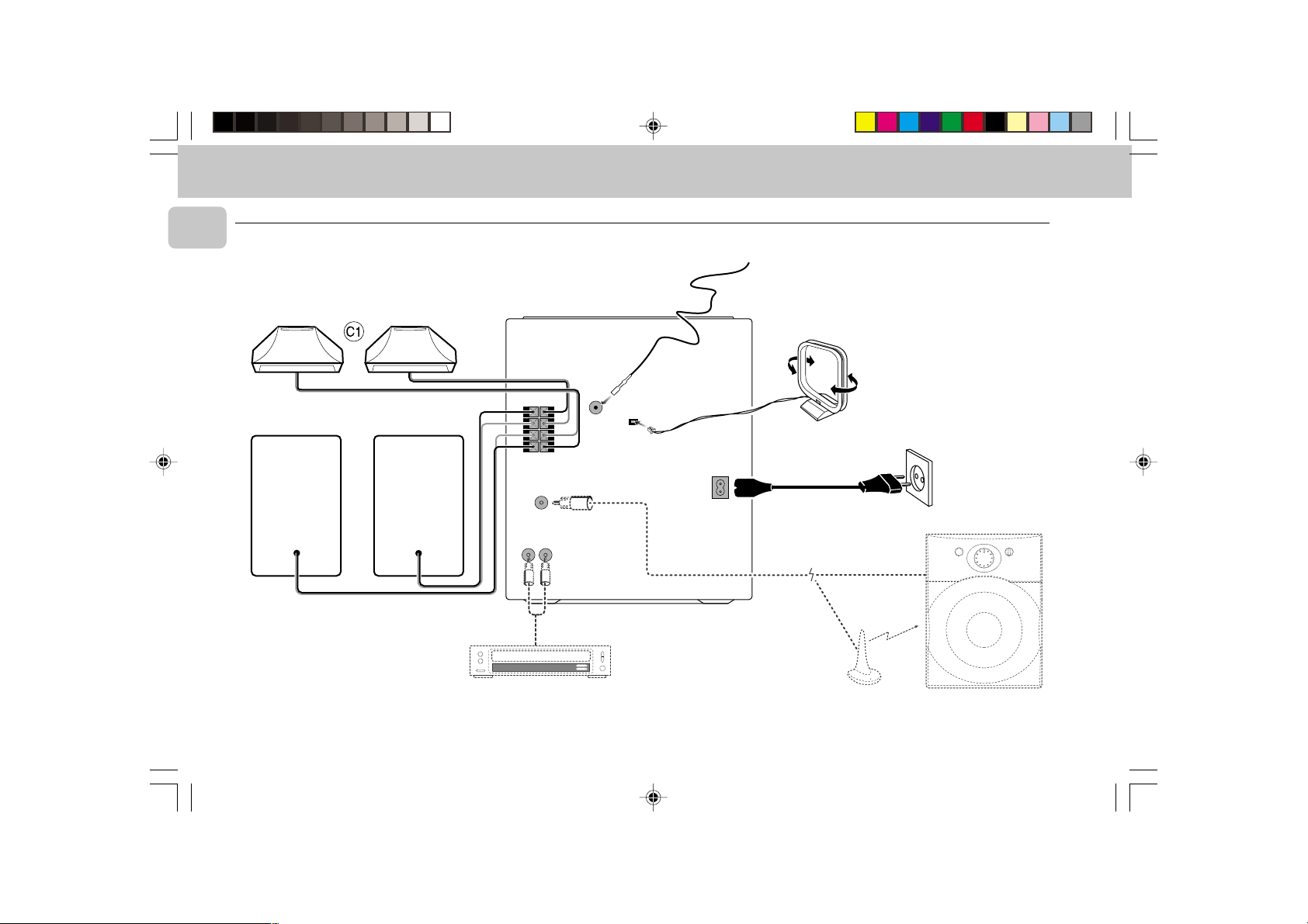
Rear Connections
LR
FRONT REAR
+
R
–
–
L
LR
+
SUBWOOFER
OUT
B
A
FM AERIAL
75Ω
+
R
–
–
L
+
AM AERIAL
F
AC
MAINS
~
C
6
Untitled-26 6/15/00, 4:51 PM6
D
AUX IN
AUDIO OUT
E
VOLUME
POWER
CROSSOVER
60 Hz 120 Hz
MIN
MAX
3139 116 17942
Page 7
PREPARATION
A AM Antenna Connection
Connect the supplied loop antenna to the AM AERIAL
terminal. Place the AM loop antenna far away from the
system and adjust its position for the best reception.
B FM Wire Antenna Connection
Connect the supplied FM wire antenna to the FM 75 Ω
terminal. Adjust the position of the FM antenna for the
best reception.
Outdoor Antenna
For better FM stereo reception connect an outdoor FM
antenna to the FM AERIAL 75 Ω terminal using a 75 Ω
coaxial wire.
C Front Speakers Connections
• Connect the right speaker to Front terminal R, with the
red wire to + and the black wire to -.
• Connect the left speaker to Front terminal L, with the
red wire to + and the
black wire to -.
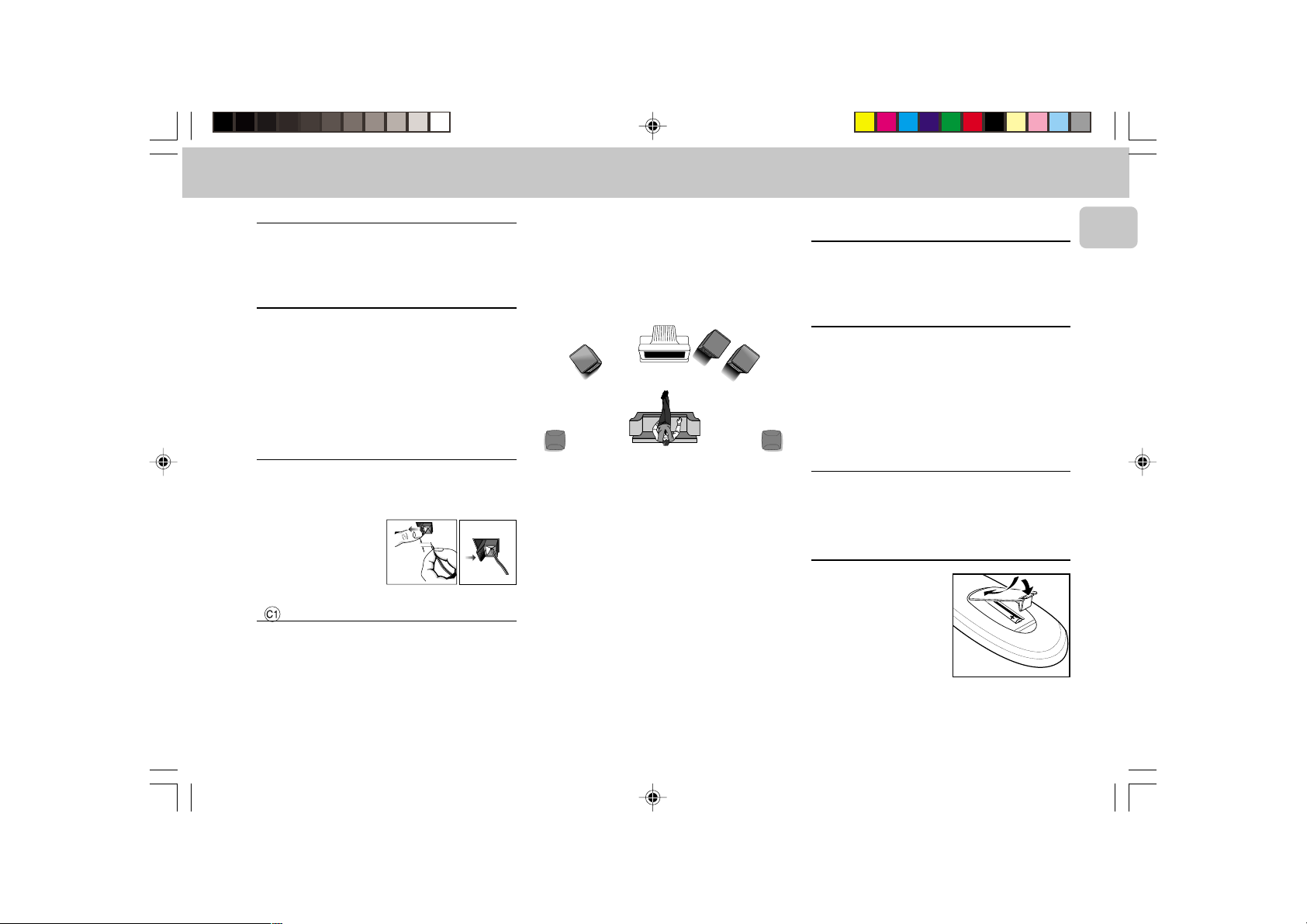
12 mm
• Clip the stripped portion
of the speaker wire as
shown.
unlock
lock
Surround Speakers Connection
4-Speakers Connection
Front speakers :
FRONT terminals and the red wires to the red FRONT
terminals.
Connect the black wires to the black
Rear (surround) speakers :
Connect the black or nonmarked wires to the black REAR terminals and the white
or marked wires to the grey REAR terminals.
Positioning the Speakers
To get the best surround sound effect, place the speakers
as follow.
MINI HIFI
SYSTEM
FRONT
RIGHT
SURROUND
RIGHT
SURROUND
LEFT
FRONT
LEFT
TV
Front Left and Right Speakers
For best listening effect, it is recommended to have the
Left and Right speakers to form an angle of
approximately 45 degrees to the listener. Should the
magnetic field from the speakers affect the picture of the
television, you should increase the separation distance.
Rear (surround) Speakers
The surround speaker should be placed at normal
listening ear level. It can also be mounted on the wall at
the back of the room. Most important , sometimes you
need to experiment creatively when placing the surround
speakers in order to obtain the most ideal sound
projection.
D Connecting other equipment to your
system
You can connect the audio left and right OUT terminals of
a TV, VCR, Laser Disc or DVD player to the AUX IN
terminals at the rear of the system.
E Subwoofer Out Connection
You can connect either an optional active subwoofer or
an optional wireless active subwoofer to the
SUBWOOFER OUT terminal. The wireless system uses a
radio frequency transmitter. The subwoofer reproduces
just the low bass effect (e.g. explosions, the rumble of
the spaceships, etc.). Be sure to follow the instructions
supplied with the subwoofer unit.
F AC Power Supply
After all other connections have been made, connect the
AC power cord to the system and to the wall outlet.
Inserting batteries into the Remote
Control
• Insert the batteries (Type
R03 or AAA) into the
remote control as shown in
the battery compartment.
• To avoid damage from
possible battery leakage,
remove dead batteries or
batteries that will not be
used for a long time. For replacement, use type R03 or
AAA batteries.
English
Untitled-26 6/15/00, 4:51 PM7
7
3139 116 17942
Page 8
CONTROLS
English
@
!
0
9
8
7
8
2
1
6
5
4
3
∞
≤
OPTIMAL
DSC
TECHNO
DIGITAL SOUND CONTROL
STANDBY.ON
DUBBING
RECORD A. REPLAY
NORMA•HIGH
CD
1
CD
2
CD
3
3 CD ROTARY CHANGER SYSTEM • CD SYNCHRO RECORDING
JAZZ
DBB
REPEAT
SHUFFLE
TIMER
ROCK
PROGRAM
FW 318C
CD TUNER TAPE AUX
CD
1
• CD2 • CD
3
▲▲▲
▲
TUNING
SEARCH
STEREO
NEWS
REPLAY
FM
MINI HIFI SYSTEM
BAND
CLEAR
STOP
REC
DBB
I S
HSD
MW
AM
LW
TAPE 1 • TAPE 2
PAUSE
PLAY
DISC CHANGE
OPEN • CLOSE
#
$
VOLUME
n
%
^
&
*
(
)
¡
™
2
9
7
§
≥
3
)
AUX
CD
123
DBB
REPEAT
á
PREV. NEXT
í
TAPE 1/2
CD DIRECT
DSC
SHUFFLE
Å
VOLUME
PLAY
É
STOP
2
TUNER
INC. SURR.
PROGRAM
á
ë
Ç
DIGITAL REMOTE CONTROL
•
@
(
*
3
3
)
3
DC
3
CHANGER
RDS NEWS!
CLOCK
MAX
PM
VIDEO
▲
PRESET
PREV NEXT
TIMER
▲
PROGRAM
SURROUND CONTROL
INCREDIBLE SURROUND
MIC LEVEL
•MAX
OPENOPEN
£
TAPE 1 TAPE 2
8
Untitled-26 6/15/00, 4:51 PM8
3139 116 17942
Page 9

CONTROLS
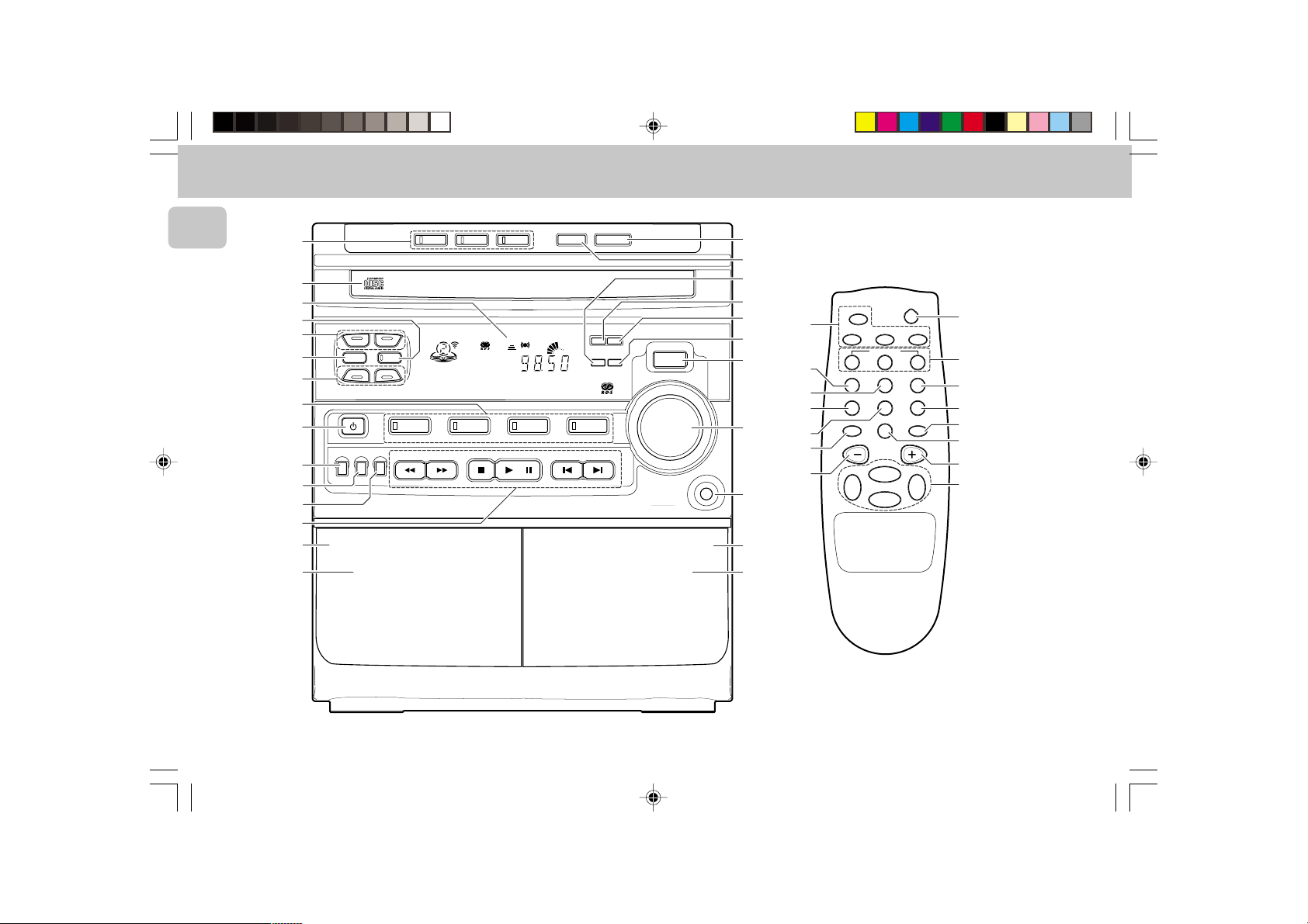
Controls on the system and remote
control
1 STANDBY-ON
– to switch the system on or to standby mode.
– to store radio stations automatically by pressing and
holding for 2 seconds.
2 SOURCE : to select the following.
CD / (CD 1•CD 2•CD 3)
– to select CD mode. When CD in stop mode; to select
the disc tray 1, 2 or 3.
TUNER / (BAND)
– to select Tuner mode. When in tuner mode; to select
the waveband: FM, MW or LW.
TAPE / (TAPE 1•TAPE 2)
– to select Tape mode. When tape in stop mode; to
select either tape deck 1 or 2.
AUX / (VIDEO)
– to select sound from an external source (e.g. TV,
Laser Disc, DVD or VCR player).
3 MODE SELECTION
SEARCH à á (TUNING à á)
for CD ............ to search backward/forward.
for TUNER ..... to tune to a lower or higher radio
frequency.
for TAPE ....... to rewind or fast forward on tape
deck 2 only.
STOP Ç (CLEAR)
for CD ............ to stop CD playback or clear a
program.
for TUNER ..... to stop programming.
for TAPE ........ to stop playback or recording.
PLAY PAUSE ÉÅ
for CD ............ to start or interrupt playback.
for TAPE ........ to start playback.
PREV í / NEXT ë (PRESET 3 4)
for CD ............ to skip to the beginning of the current
for TUNER ..... to select a preset station in memory.
4 AUTO REPLAY
– to select playback mode either in continuous AUTO
PLAY or ONCE only.
5 RECORD
– to start recording on tape deck 2 only.
6 DUBBING
– to dub a tape in normal or high speed.
7 DIGITAL SOUND CONTROL (DSC)
– to select the desired sound effect : OPTIMAL, JAZZ,
ROCK or TECHNO.
8 DIGITAL SOUND CONTROL DISPLAY PANEL
– to view the selected DSC display.
9 DYNAMIC BASS BOOST (DBB)
– to switch on bass boost to enhance bass response or
to switch off bass boost.
0 DISPLAY
– to view the current setting of the system.
! CD CAROUSEL TRAY
@ 3 CD DIRECT PLAY
– to select a CD tray for playback.
# OPEN•CLOSE
– to open or close the CD carousel tray.
$ DISC CHANGE
– to change CD(s).
% CLOCK•TIMER
– to view clock, set clock or timer.
or previous/next track.
(available in tape deck 2 only)
^ RDS
– to select RDS data.
& NEWS!
– to hear news at a preset time automatically.
* PROGRAM
– to program CD tracks in CD mode or to preset radio
stations in tuner mode.
( INCREDIBLE SURROUND
– to switch on or off the surround sound effect.
) VOLUME
– to adjust the volume level.
¡ n
– to connect headphones.
™ OPEN
– to open tape deck 2.
£ TAPE DECK 2
≤ TAPE DECK 1
∞ OPEN
– to open tape deck 1.
§ REPEAT
– to repeat a CD track.
≥ SHUFFLE
– to play all the available discs and their tracks in
random order.
• B
– to switch the system to standby mode.
Notes for remote control:
– First select the source you wish to control by pressing
one of the source select keys on the remote control
(e.g. CD, TUNER, TAPE 1/2 or AUX).
– Then select the desired function (PLAY, NEXT, etc.).
English
9
Untitled-26 6/15/00, 4:51 PM9
3139 116 17942
Page 10

OPERATING THE SYSTEM
English
JAZZ
OPTIMAL
DSC
TECHNO
DIGITAL SOUND CONTROL
STANDBY.ON
DUBBING
RECORD A. REPLAY
NORMA•HIGH
DBB
ROCK
CD
1
• CD2 • CD
3
▲▲▲
TUNING
SEARCH
REPEAT
SHUFFLE
TIMER
PROGRAM
FW 318C
▲
STEREO
REPLAY
Important:
Before you begin operating the system, complete
the preparation procedures.
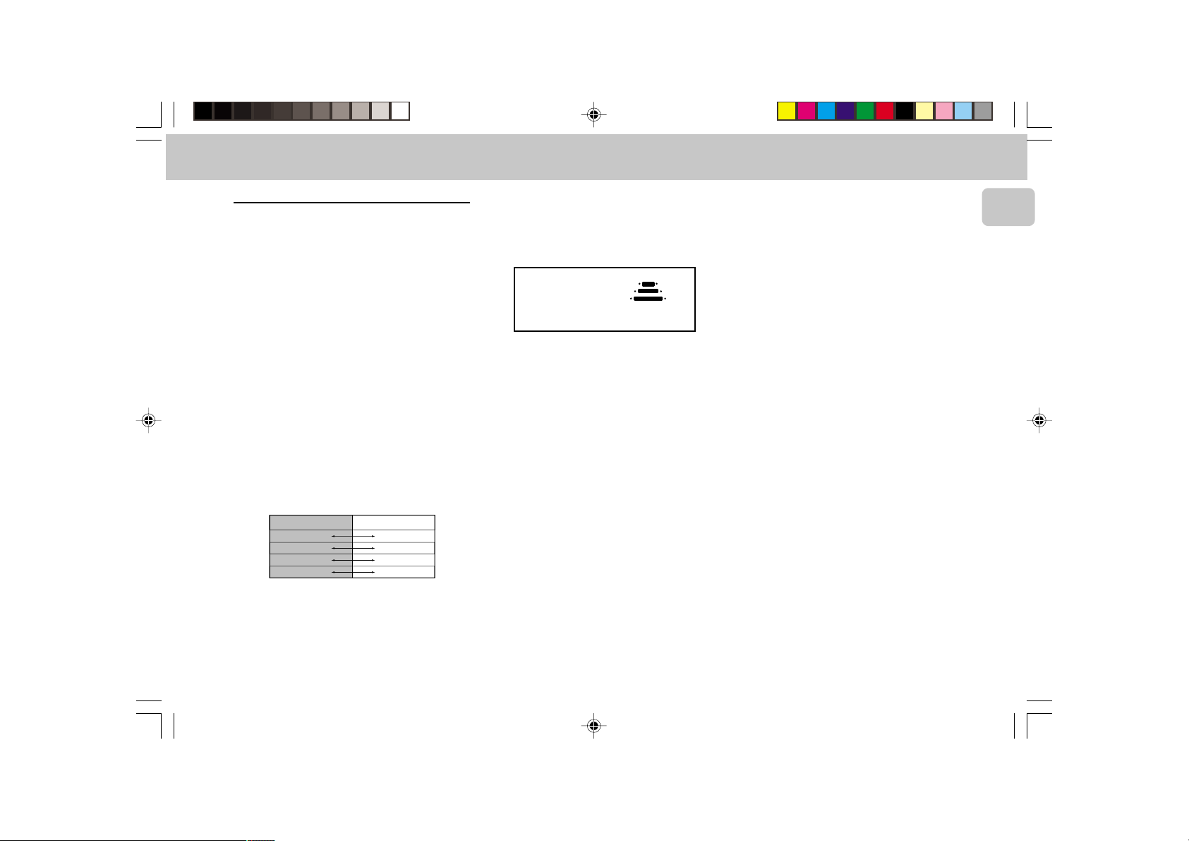
Demonstration mode
The system has a demonstration mode that shows the
various features offered by the system.
system is switched on from the wall socket, the
demonstration mode will start automatically.
Note:
– During demonstration mode, if you press any source
(or standby-on) button, the system will switch to the
respective (or standby) mode.
– When the system is switched to standby mode, 5
seconds later, the demonstration mode will resume.
Whenever the
NEWS
FM
MINI HIFI SYSTEM
BAND
CLEAR
STOP
REC
HSD
MW
DBB
LW
TAPE 1 • TAPE 2
PLAY
RDS NEWS!
I S
AM
PM
PAUSE
CLOCK
MAX
TIMER
AUXTAPETUNERCD
VIDEO
▲
PRESET
PREV NEXT
PROGRAM
▲
SURROUND CONTROL
INCREDIBLE SURROUND
To cancel demonstration mode
• Press and hold STOP Ç
seconds
to stop the demonstration.
(on the system only)
™ The demonstration mode will be switched off
permanently.
™ The system will switch to standby mode.
Easy Set
EASY SET allows you to store all available radio stations
in a particular band (FM, MW or LW) automatically.
• Press and hold STANDBY•ON
for 2 seconds; when the system is in standby or
demonstration mode.
™ "EASY SET" will be displayed and followed by
"TUNER".
™ EASY SET will start with the last active band.
(on the system only)
VOLUME
for
™ All available radio stations with sufficient signal
strength will be stored or until 40 presets are filled.
Notes :
– When EASY SET is used, all previously stored stations
will be erased.
– The last preset station will appear on the display
when EASY SET is completed.
Switching the system ON
• Press STANDBY•ON
TUNER, TAPE or AUX.
n
You can also switch on the system by pressing any one of
the 3 CD DIRECT PLAY buttons.
(on the system only)
Switching the system to standby mode
• Press STANDBY•ON again.
3
™ The system will switch to standby mode.
Selecting the Source
• Press the respective source selection button: CD,
TUNER, TAPE or AUX.
™ The display indicates the selected source.
Note:
– For an external source, make sure that you have
connected the audio left and right OUT terminals of
the external equipment (TV, VCR, Laser Disc or DVD
player) to the AUX IN terminals.
, CD,
10
Untitled-26 6/15/00, 4:52 PM10
3139 116 17942
Page 11
OPERATING THE SYSTEM
Sound Control
Volume Adjustment
Adjust VOLUME to increase or decrease the sound level.
For Personal Listening
Connect the headphones plug to the n socket at the
front of the system. The speakers will be muted.
Digital Sound Control (DSC)
The DSC feature enables you to enjoy special sound
effects that have preset equalizer settings, providing the
best music reproduction.
• Press DIGITAL SOUND CONTROL (DSC) to select
OPTIMAL, JAZZ, ROCK or TECHNO.
™ The Digital Sound Control display panel will light up
respectively.
™ “OPTIMAL, JAZZ, ROCK or TECHNO” will
be displayed.
Automatic DSC-DBB selection
The best setting for the DBB is automatically generated
for the respective DSC selection. You can manually select
the DBB setting that best suits your listening
environment.
DSC Selection
Optimal
Techno
Rock
Jazz
DBB On/Off
On
On
Off
Off
Dynamic Bass Boost (DBB)
The DBB mode enhances the bass response.
• Press DBB to switch on bass boost.
™ The DBB button lights up.
™ “DBB ON” will be displayed.
DBB DBB
DBB
OFF
DBB
ON
To switch off DBB
• Press DBB again.
™ The DBB button light is switched off.
™ “DBB OFF” will be displayed.
Note:
– Some CDs or tapes might be recorded in high
modulation. It may cause a distortion at high volume.
If this occurs, switch off Incredible Surround or DBB
level or reduce the volume.
Incredible Surround
Normal stereo sound is determined by the distance
between the front speakers. When Incredible Surround is
switched on, it magnifies the virtual distance between
the front speakers for an incredibly wide, enveloping,
stereo effect.
• Press INCREDIBLE SURROUND to switch on.
™ The INCREDIBLE SURROUND button lights up.
™ “IS” will be displayed.
To switch off Incredible Surround
• Press INCREDIBLE SURROUND again.
™ The INCREDIBLE SURROUND button light is
switched off.
™ “IS OFF” will be displayed.
English
Untitled-26 6/15/00, 4:52 PM11
11
3139 116 17942
Page 12

CD
English
OPTIMAL
DSC
TECHNO
DIGITAL SOUND CONTROL
STANDBY.ON
DUBBING
RECORD A. REPLAY
NORMA•HIGH
PM
DISC CHANGE
MAX
PREV NEXT
CD
1
CD
2
CD
3
3 CD ROTARY CHANGER SYSTEM • CD SYNCHRO RECORDING
JAZZ
DBB
ROCK
REPEAT
PROGRAM
SHUFFLE
TIMER
FW 318C
1
• CD2 • CD
3
CD
▲▲▲
▲
TUNING
SEARCH
STEREO
NEWS
REPLAY
FM
MINI HIFI SYSTEM
BAND
CLEAR
STOP
REC
HSD
MW
DBB
LW
TAPE 1 • TAPE 2
PLAY
I S
AM
PAUSE
OPEN • CLOSE
DC
3
CHANGER
RDS NEWS!
CLOCK
PROGRAM
TIMER
AUXTAPETUNERCD
VIDEO
▲
▲
PRESET
SURROUND CONTROL
INCREDIBLE SURROUND
MIC LEVEL
•MAX
Warning!
1) This system is designed for conventional CDs. Do not use any accessories like disc stabilizer rings or
CD treatment sheets, etc., which may damage the CD mechanism.
2) Do not load more than one disc into each tray.
3) When the CD changer is loaded with CD(s), do not turn over or shake the system. This may jam the
changer.
You can load up to three discs in the CD changer for continuous playback without interruption.
VOLUME
n
Loading the CD Changer
1 Press CD to select CD mode.
2 Press OPEN•CLOSE.
™ The CD compartment slides out.
3 Load a CD with the printed side up in the right tray.
• You can load another disc in the left tray.
• To load the third disc, press the DISC CHANGE
button.
™ The CD changer carousel will rotate until the empty
tray is at the right hand side and is ready for
loading.
™ Playback will always start with the disc in the outer
right disc tray.
4 Press OPEN•CLOSE to close the CD compartment.
™ The total number of tracks and playing time of the
last selected disc appear on the display.
3 CD Direct Play
You can play a CD directly by pressing the 3 CD DIRECT
PLAY (1 - 3) buttons. The CD player will stop at the end
of playback of the selected disc.
– When the button is lighted, it indicates that there is a
disc loaded in the disc tray.
12
Untitled-26 6/15/00, 4:52 PM12
3139 116 17942
Page 13

CD
Playing a CD
1 Press PLAY É to start playback.
™ The disc tray, track number and elapsed playing
time of the current track appear on the display.
• To interrupt playback, press PAUSE Å.
™ The playing time flashes.
• To resume playback, press PLAY É again.
2 To stop playback, press STOP Ç.
Note:
– All the available discs will play once, then stop. When
the CD has stopped playing, the system will switch to
the standby mode after 15 minutes if no button is
pressed.
Disc Change
You can change the outer 2 discs while the third inner
disc is at the stop or playing mode.
1 Press DISC CHANGE.
™ The CD compartment slides out.
2 Replace the discs in the left and right disc trays.
• If you press DISC CHANGE again during playback,
the CD will stop playing.
™ The CD carousel tray will rotate until the inner tray
is at the right hand side and is ready for changing.
3 Press OPEN•CLOSE to close the CD compartment.
Selecting a desired track
Selecting a desired track at the stop mode
1 Press PREV í or NEXT ë until the desired track
appears on the display.
2 Press PLAY É to start playback.
™ The selected track number and elapsed playing
time appear on the display.
Selecting a desired track during playback
1 Press PREV í or NEXT ë until the desired track
appears on the display.
™ The selected track number and elapsed playing
time appear on the display.
• If you press PREV í once it will skip to the
beginning of the current track and play the track again.
Searching for a particular passage
during playback
• Press and hold à or á until the desired passage is
located.
™ The volume will be reduced.
• Play returns to normal when à or á is released.
Programming Tracks
Programming tracks of a loaded CD is possible in the stop
mode. The display will indicate the total tracks stored in
the program. Up to 40 tracks can be stored in the memory
in any order. When 40 tracks are stored and you attempt
to store another track, the display will show “PROGRAM
FULL”.
1 Load the desired discs in the disc trays.
2 Press PROGRAM to start programming.
™ The PROGRAM flag starts flashing.
3 Press the CD 1•CD 2•CD 3 button to select the disc.
4 Press PREV í or NEXT ë to select the desired
track.
5 Press PROGRAM to store the track.
• Repeat steps 3 to 5 to store other discs and tracks.
6 Press STOP Ç once to end programming mode.
™ The total number of tracks programmed and total
playing time appear on the display.
Note:
– If the total playing time is more than “
one of the programmed tracks has a number greater
than 30, then “
of the total playing time.
– During programming, if no button is pressed within 20
seconds, the system will exit program mode
automatically.
--:--
” appears in the display instead
99:59
” or if
English
Untitled-26 6/15/00, 4:52 PM13
13
3139 116 17942
Page 14

CD
English
Playing the program
1 Press PLAY É to start program playback.
™ “PLAY PROGRAM” appears on the display.
™ The track number and elapsed playing time of the
current track will appear on the display.
• If you press REPEAT during program playback, the
current track will be played repeatedly.
™ The REPEAT and PROGRAM flags will be displayed.
2 Press STOP Ç to stop program playback.
Note:
– If you press any of the 3 CD DIRECT PLAY buttons, the
system will play the selected disc or track and the
stored program will be ignored temporarily. The
PROGRAM flag will also temporarily disappear from
the display and then reappear when the playback for
the selected disc ends.
Reviewing the program
Reviewing of the program is only possible in the stop
mode.
• Press PREV í or NEXT ë repeatedly to review the
programmed tracks.
• Press STOP Ç to exit review mode.
Erasing the program
• Press CLEAR on the system.
™ “PROGRAM CLEARED” will be displayed.
Note:
– The program will be erased when the system is
disconnected from the power supply. If the CD
carousel is opened, the tracks belonging to the outer
two trays will be erased and the display will show
“
CLEARED
Shuffle
It will play all the available discs and their tracks in
random order. Shuffle may also be used when tracks are
programmed.
To shuffle all the discs and tracks
1 Press SHUFFLE.
™ “SHUFFLE” will be displayed.
™ The SHUFFLE flag, the disc and the track selected
• The discs and the tracks will now be played in random
order until you press STOP Ç.
• If you press REPEAT during shuffling, the current track
will be played repeatedly.
™ The REPEAT and SHUFFLE flags will be displayed.
2 Press SHUFFLE again to resume normal playback.
™ The SHUFFLE flag disappears from the display.
” .
(only on remote control)
at random appear on the display.
(in the stop mode)
Repeat
It will play the current track repeatedly.
1 Press REPEAT during CD playback.
• The track will now be played repeatedly until you
2 Press REPEAT again to resume normal playback.
(only on remote control)
™ “REPEAT TRACK” will be displayed.
™ The REPEAT flag appears on the display.
press STOP Ç.
™ The REPEAT flag disappears from the display.
14
Untitled-26 6/15/00, 4:52 PM14
3139 116 17942
Page 15
TUNER
JAZZ
OPTIMAL
DSC
TECHNO
DIGITAL SOUND CONTROL
STANDBY.ON
DUBBING
RECORD A. REPLAY
NORMA•HIGH
DBB
ROCK
REPEAT
PROGRAM
SHUFFLE
TIMER
FW 318C
1
• CD2 • CD
3
CD
▲▲▲
▲
TUNING
SEARCH
STEREO
NEWS
REPLAY
FM
MINI HIFI SYSTEM
BAND
CLEAR
STOP
REC
HSD
MW
Easy Set
EASY SET allows you to store all available radio stations
in a particular band (FM, MW or LW) automatically.
1 Press and hold STANDBY•ON
for 2 seconds; when the system is in standby or
demonstration mode.
™ "EASY SET" will be displayed and followed by
"TUNER".
™ EASY SET will start with the last active band.
™ All available radio stations with sufficient signal
strength will be stored or until 40 presets are filled.
2 The system will search once again for the first
available RDS station and to set the RDS time
automatically.
(on the system only)
DBB
LW
TAPE 1 • TAPE 2
PLAY
RDS NEWS!
I S
AM
PM
PAUSE
CLOCK
MAX
TIMER
AUXTAPETUNERCD
VIDEO
▲
PRESET
PREV NEXT
PROGRAM
▲
SURROUND CONTROL
INCREDIBLE SURROUND
MIC LEVEL
• When searching RDS station;
™ “SEARCH RDS STATION” will be displayed. If
no RDS station is available, the program will exit
automatically and "NO RDS STATION" will be
displayed.
™ After a station is found, “EASY SET” will be
displayed and followed by “TIME”.
• When searching RDS time;
™ “SEARCH RDS TIME” will be displayed.
™ When RDS time is read, “RDS TIME” will be
displayed. The current time is displayed for 2
seconds and will be stored automatically.
Notes :
– When EASY SET is used, all previously stored radio
stations will be erased.
English
– The last preset radio station will appear on the display
VOLUME
when EASY SET
Tuning to radio stations
is completed.
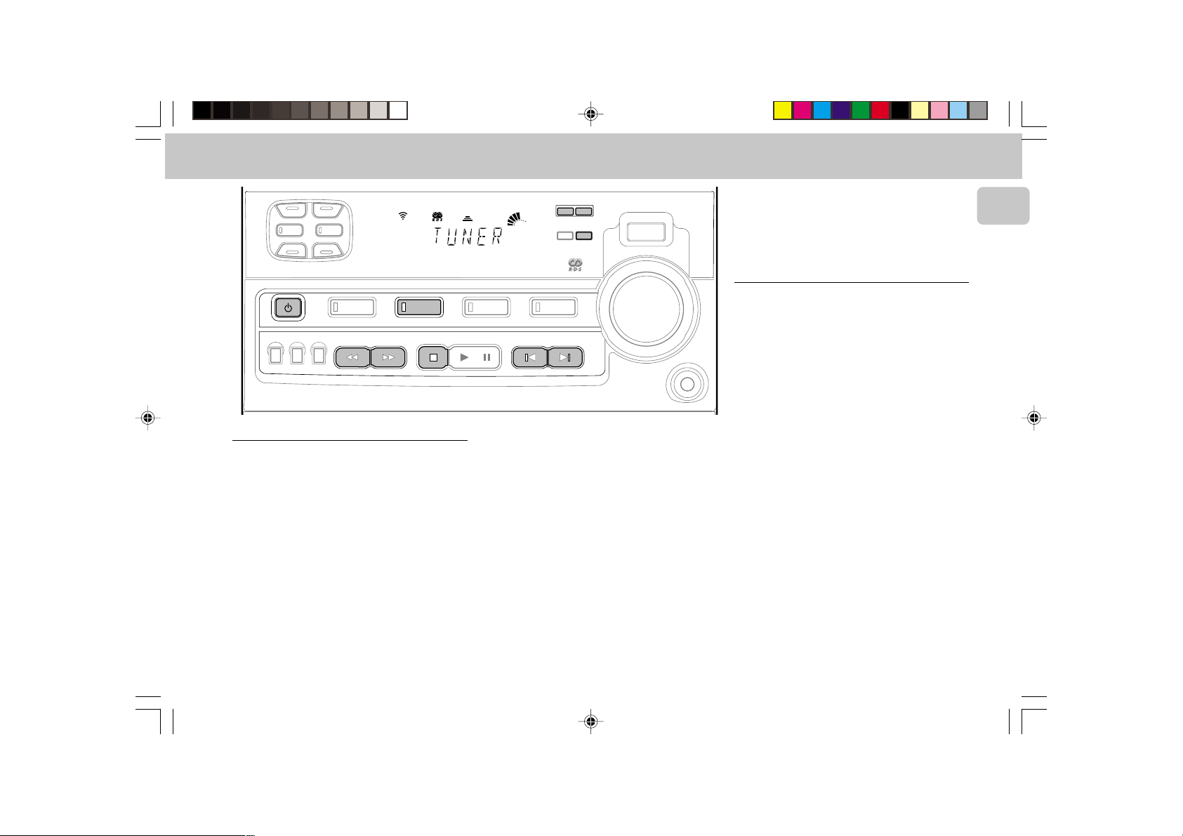
1 Press TUNER to select TUNER mode.
™ "TUNER" will be displayed.
A few seconds later, the current frequency or the
radio station name if available will be displayed.
2 Press TUNER (BAND) again to select the desired
n
waveband : FM, MW or LW.
3 Press TUNING à or á for more than one second,
•MAX
then release.
™ The display will show ‘SEARCH’ until a radio
station with sufficient signal strength is found.
• Repeat this procedure until the desired station is
reached.
• To tune to a weak station, briefly press TUNING à
or á until the display shows the desired frequency
and/or when the best reception has been obtained.
Untitled-26 6/15/00, 4:52 PM15
15
3139 116 17942
Page 16

TUNER
English
Storing Preset Stations
You can store up to 40 radio stations in the memory.
When a preset radio station is selected, the preset
number appears next to the frequency on the display.
Automatic programming
1 Press TUNER.
2 Press TUNER (BAND) again to select the desired
waveband : FM, MW or LW.
3 Press PROGRAM for more than one second.
™ PROGRAM flag starts flashing and ‘AUTO’ will be
displayed.
™ Every available station for the selected waveband
will be stored automatically. The frequency and
preset number will be displayed briefly.
™ The system will stop searching when all the
available radio stations are stored or when the
memory for 40 preset radio stations is used.
™ The system will remain tuned to the last stored
preset radio station.
• Repeat the above procedure to store other preset radio
stations for the other waveband. Remember to select
the next available preset number before proceeding. If
not, some of the preset radio stations may be erased.
Notes:
– You can cancel the automatic programming by
pressing PROGRAM or STOP Ç (on the system only) .
– If you want to reserve a section of preset numbers, for
example preset numbers 1 to 9, select preset 10
before starting automatic programming: now only the
preset numbers 10 to 40 will be programmed.
Manual programming
1 Press TUNER.
2 Press TUNER (BAND) to select the desired waveband
: FM, MW or LW.
3 Press PROGRAM for less than one second.
™ PROGRAM flag, the frequency and preset number
start flashing.
™ The next available preset number will be displayed
for selection.
4 Press TUNING à or á to tune to the desired
frequency.
• If you wish to store the radio station to another preset
number, press PRESET 4 or 3 to select the desired
preset number.
5 Press PROGRAM again.
™ PROGRAM flag will stop flashing, and the radio
station will be stored.
• Repeat the above procedure to store other preset radio
stations.
Notes:
– When 40 radio stations are stored and you attempt to
store another radio station, the display will show
"
PROGRAM FULL
”. If you want to change an
existing preset number; repeat steps 4 and 5.
– You can cancel manual programming by pressing
STOP Ç (on the system only) .
– During programming, if no button is pressed within 20
seconds, the system will exit program mode
automatically.
Tuning to Preset Radio Stations
• Press PRESET 4 or 3 to select the desired preset
number.
™ The preset number, frequency and waveband
appear on the display
Receiving RDS radio station Ç
RDS (Radio Data System) is a broadcasting service that
allows FM stations to send additional information along
with the regular FM radio signal. This additional
information can contain:
• STATION NAME: The station name is displayed.
• FREQUENCY: The frequency of the station is
displayed.
• PROGRAM TYPE: The following program types exist
and can be received by your tuner: News, Affairs, Info,
Sport, Educate, Drama, Culture, Science, Varied, Pop
M, Rock M, M.O.R. (middle of the road music), Light
M, Classics, Other M, No type.
• RADIO TEXT (RT): text messages appear in the
display.
When you have tuned to a RDS station, the RDS logo (Ç)
and the station name will appear on the display:
• The display normally shows the radio station name if
available. By repeatedly pressing RDS button you can
change the type of display information:
™ The display shows in turn:
STATION NAME ™ FREQUENCY ™
PROGRAM TYPE ™ RADIO TEXT ™
STATION NAME ...
16
Untitled-26 6/15/00, 4:52 PM16
3139 116 17942
Page 17
TUNER
Note:
– When you press the RDS button and the display
shows "
NO RDS
", it indicates that either the tuned
station is not transmitting RDS signal or it is a non RDS
station.
RDS Time
Some RDS station may be transmitting a real time clock
at an interval of every minute.
Setting the time with RDS clock
1 Press CLOCK•TIMER.
™ "--:--" or current time appears on the display.
2 Press CLOCK•TIMER once more to enter clock setting
mode.
™ "00:00" or current time starts flashing.
3 Press RDS.
™ The message "SEARCH RDS TIME" will be
displayed.
™ If the station does not transmit RDS clock, "NO
RDS TIME" will be displayed.
™ When the RDS clock is read, "RDS TIME" will be
displayed. The current clock time is displayed for 2
seconds and will be stored automatically.
News
(only available in Radio Station with RDS)
You can activate NEWS function in Standby or any source
mode except Tuner mode. Once the News PTY (program
type) is detected in a RDS station, it will switch to TUNER
mode automatically.
To start NEWS function
1 Press NEWS.
• The NEWS flag and "NEWS ON" will be displayed.
• It will search for the first available RDS station in the
presets and wait for the News PTY (program type) to
be available. During News PTY search :
™ If NEWS activate from Standby or Demo mode, the
display will show "WAITING FOR NEWS".
™ If NEWS is activated from CD, Tape or Aux mode,
the current source activity will be remain
uninterrupted.
™ If no RDS station is found after the search, the
News function will be switched off. The display
will show "NO RDS NEWS" and NEWS flag will
disappear from the display.
• When News transmission is detected, the system will
switch to Tuner mode.
™ The NEWS flag starts flashing.
• After News has ended, the last selected source mode
will be resumed.
™ The NEWS flag will disappear from the display.
To cancel NEWS function
• Press NEWS again.
™ The NEWS flag disappears and "NEWS OFF" will
be displayed.
™ The last selected source mode will be resumed.
Notes:
– During NEWS bulletin, you can press any available
source button to cancel NEWS function and execute
the relevant source mode.
– The NEWS works only once for each activation.
– If NEWS is activated from Standby or Demostration
mode, it switches to Tuner mode and the sound will be
muted until News is available.
English
Untitled-26 6/15/00, 4:52 PM17
17
3139 116 17942
Page 18
TAPE
English
OPTIMAL
DSC
TECHNO
DIGITAL SOUND CONTROL
STANDBY.ON
DUBBING
RECORD A. REPLAY
NORMA•HIGH
JAZZ
DBB
ROCK
CD
1 • CD2 • CD3 BAND
▲▲▲
TUNING
SEARCH
STEREO
REPLAY
REPEAT
SHUFFLE
TIMER
PROGRAM
FW 318C
▲
NEWS
FM
MINI HIFI SYSTEM
CLEAR
STOP
REC
HSD
MW
DBB
LW
TAPE 1 • TAPE 2
PLAY
RDS NEWS!
I S
AM
PM
TAPE
PAUSE
MAX
AUXTUNERCD
VIDEO
▲
PRESET
PREV NEXT
TIMER
CLOCK
▲
PROGRAM
SURROUND CONTROL
INCREDIBLE SURROUND
MIC LEVEL
TAPE 1 TAPE 2
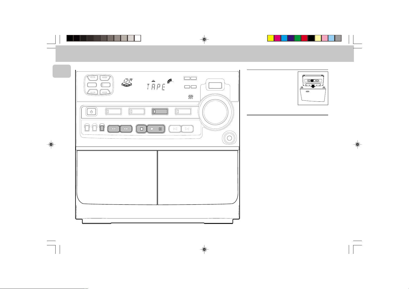
Loading a tape
• Press OPEN.
• The tape deck door opens.
• Load the tape with the open
side downward and the full
spool to the left.
VOLUME
• Close the tape deck door.
Tape Playback
1 Press TAPE to select TAPE mode.
n
•MAX
OPENOPEN
™ "TAPE 1" or "TAPE 2" will be displayed.
• Press TAPE again to select either tape deck 1 or tape
deck 2.
2 Load the tape into the selected tape deck.
3 Press PLAY É to start playback.
3a(For Tape Deck 2 only)
Press A. REPLAY to select the different type of play
mode
(see auto replay)
.
4 Press STOP Ç to end playback.
Note:
– When the tape has stopped playing, the system will
switch to the standby mode automatically after 15
minutes if no button is pressed.
18
Untitled-26 6/15/00, 4:52 PM18
3139 116 17942
Page 19

TAPE AUX
A
S
Auto Replay
(only on tape deck 2)
• Press A. REPLAY to select either continuous AUTO
REPLAY or ONCE during tape playback.
™ "AUTO REPLAY" or "ONCE" will be displayed.
Notes:
– This feature is available during tape playback only.
– When "
AUTO REPLAY
" is selected, the tape will
rewind automatically at the end of playback for the
selected side. Then it will start playing again. It will
replay upto a maximum of 20 times or when you press
STOP Ç.
– When "
ONCE
" is selected, the tape will play the
selected side once and then stop.
Rewind/Fast Forward
(only on tape deck 2)
At the stop mode
1 You can rewind or fast forward the tape by pressing
à or á respectively.
™ "OOO" or "PPP" will be displayed depending on which
button is pressed.
™ The tape will stop automatically at the end of the
rewinding or fast forwarding.
2 Press STOPÇ to stop rewind or fast forward.
During playback
• Press and hold à or á respectively until the desired
passage is located.
™ During searching, the sound is reduced to a low
volume.
™ When you release à or á, the tape continues
playing.
Notes:
– During rewinding or fast forwarding of a tape, it is
possible to select another source (e.g. CD, TUNER or
AUX ).
– Check and tighten slack tape with a pencil before use.
Slack tape may get jammed or may burst in the
mechanism.
– C-120 tape is extremely thin and is easily deformed or
damaged. It is not recommended for use in this
system.
– Store the tapes at room temperature and do not put
them too close to a magnetic field (for example, a
transformer, TV or loudspeaker boxes).
RDS NEW
CLOCK
MAX
VIDEO
PROGR
TIMER
AUXTUNER TAPE
REPEAT
SHUFFLE
PROGRAM
FW 318C
3
TIMER
STEREO
NEWS
REPLAY
FM
MINI HIFI SYSTEM
BAND
REC
HSD
MW
DBB
LW
TAPE 1 • TAPE 2
I S
AM
PM
Selecting External Equipment
If you have connected the audio out terminals of the
external equipment (TV, VCR, Laser Disc or DVD player) to
the AUX IN terminals, you can hear the enhanced sound
from the system.
• Press AUX to select the external mode.
™ "AUX" will be displayed.
Note:
– All the sound control features (e.g. DSC, DBB, etc.) are
available for selection.
English
Untitled-26 6/15/00, 4:52 PM19
19
3139 116 17942
Page 20

RECORDING
English
OPTIMAL
DSC
TECHNO
DIGITAL SOUND CONTROL
STANDBY.ON
DUBBING
RECORD A. REPLAY
NORMA•HIGH
JAZZ
DBB
ROCK
REPEAT
PROGRAM
SHUFFLE
TIMER
FW 318C
CD
1
• CD2 • CD
3
▲▲▲
▲
TUNING
SEARCH
STEREO
NEWS
REPLAY
FM
MINI HIFI SYSTEM
BAND
CLEAR
STOP
REC
HSD
MW
DBB
LW
TAPE 1 • TAPE 2
PLAY
I S
AM
PM
TAPE
PAUSE
CLOCK
MAX
TIMER
AUXTUNERCD
VIDEO
▲
PRESET
PREV NEXT
RDS NEWS!
PROGRAM
▲
SURROUND CONTROL
INCREDIBLE SURROUND
MIC LEVEL
•MAX
TAPE 1 TAPE 2
Notes:
– For recording, use only tape of IEC type I (normal tape)
or IEC type II (Chrome).
– The tape is secured at both ends with leader tape. At
the beginning and end of tape, nothing will be
recorded for six to seven seconds.
VOLUME
– The recording level is set automatically, regardless of
the position of VOLUME, DBB or Incredible Surround.
– To prevent accidental recording, break out the tab on
the left shoulder of the tape side that you want to
protect.
– If "
CHECK TAPE
" is displayed, the protection tab
has been broken. Put a piece of clear adhesive tape
n
over the opening. Do not cover the Chrome tape
detection hole when covering the tab opening.
One Touch Recording
• For One Touch Recording, as soon as you press
OPENOPEN
RECORD, the current source will be recorded on tape
deck 2.
1 Load a blank tape in tape deck 2.
2 Press RECORD to start recording.
™ REC flag starts flashing.
3 Press STOP Ç to stop recording.
Note:
– When you press RECORD at TAPE mode, “
OTHER SOURCE
” will be displayed. One Touch
SELECT
Recording is not possible at TAPE mode.
20
Untitled-26 6/15/00, 4:52 PM20
3139 116 17942
Page 21

RECORDING CLOCK
Dubbing tapes
1 Press TAPE to select tape deck 2 .
2 Load the prerecorded tape into tape deck 1 and a
blank tape into tape deck 2.
™ Make sure that the tape in tape deck 1 has its full
spool to the left.
3 Press DUBBING
twice
within 2 seconds
™ "NORMAL" (normal speed) or "FAST" (high speed)
will be displayed and then followed by
"DUBBING".
™ HSD flag appears on the display for high speed
dubbing.
• Dubbing will start immediately.
™ REC flag starts flashing.
4 Press STOP Ç to stop dubbing.
(from tape deck 1 to tape deck 2)
once
for normal speed dubbing or
for high speed dubbing.
Notes:
– At the end of side A, flip the tapes to side B and
repeat the procedure.
– Dubbing of tapes is only possible from tape deck 1 to
tape deck 2.
– To ensure good dubbing, use tapes of the same length.
– During high speed dubbing in Tape mode, the sound is
reduced to a low volume.
– You can switch to other source while dubbing.
CD Synchro Start Recording
1 Load a blank tape into tape deck 2 and a disc into the
disc tray.
2 Press CD to select CD mode .
™ You can program the tracks in the order you want
them to be recorded (see Programming Tracks). If
not, the tracks are recorded according to the
selected disc.
3 Press RECORD to start recording.
™ REC flag starts flashing.
• CD will start playback automatically.
4 Press STOP Ç to stop recording.
Recording from other sources
deck 2)
1 Load a blank tape into tape deck 2.
2 Press CD, TUNER or AUX.
• Start playback of the selected source.
3 Press RECORD to start recording.
™ REC flag starts flashing.
4 Press STOP Ç to stop recording.
Note:
– During recording, it is not possible to listen to another
sound source.
(only on tape
View Clock
You can view the clock (if it is set) at standby or any
source mode. It will be displayed for about 7 seconds.
• Press CLOCK•TIMER briefly.
™ “10:25” (the current time) will be displayed.
™ “--:--” will be displayed if the clock is not set.
Clock Setting
The clock is set in 24-hour mode, e.g. “00:00“ or
“23:59“. Before setting the clock, you must be in the
View Clock mode.
1 Press CLOCK•TIMER to select clock mode.
™ “00:00” or the current time starts flashing.
™ “à , á , í , ë, Ç” light up.
2 Set the hour with à or á.
3 Set the minute with í or ë.
4 Press CLOCK•TIMER again to store the setting.
™ The clock starts running.
• To exit without storing the setting, press STOP Ç.
Notes:
– During clock setting, if no button is pressed within 90
seconds, the system will exit clock setting mode
automatically.
– When a power interruption occurs, the clock setting is
erased.
– To set the time with RDS clock, see "Receiving RDS
Radio Station" under TUNER section.
English
Untitled-26 6/15/00, 4:52 PM21
21
3139 116 17942
Page 22

TIMER
English
JAZZ
OPTIMAL
DSC
TECHNO
DIGITAL SOUND CONTROL
STANDBY.ON
DUBBING
RECORD A. REPLAY
NORMA•HIGH
DBB
ROCK
CD
1
• CD2 • CD
3
▲▲▲
TUNING
SEARCH
REPEAT
SHUFFLE
TIMER
PROGRAM
FW 318C
▲
STEREO
NEWS
REPLAY
BAND
Timer Setting
• The system can switch on to CD, TUNER or TAPE 1
mode automatically at a preset time. It can serve as an
alarm to wake you up. After half an hour from the
preset time, the system will return to the standby
mode if no button is pressed.
• Before setting the timer, make sure the clock is set
correctly.
• The timer has to be reset or start again for each
subsequent preset time.
• The volume of the timer will be at the last setting
before the set is switched to standby mode.
REC
DBB
HSD
MW
FM
LW
MINI HIFI SYSTEM
CLEAR
PLAY
STOP
I S
AM
TAPE 1 • TAPE 2
PAUSE
PM
CLOCK
MAX
TIMER
AUXTAPETUNERCD
VIDEO
▲
PRESET
PREV NEXT
RDS NEWS!
PROGRAM
▲
SURROUND CONTROL
INCREDIBLE SURROUND
MIC LEVEL
•MAX
1 Press and hold CLOCK•TIMER for more than 2
seconds to select timer mode.
™ “ON 00:00” or the last set timer starts flashing.
The TIMER flag flashes.
™ The last selected source is lighted while other
available sources are flashing.
™ “à , á , í , ë, Ç” light up.
2 Press CD, TUNER or TAPE to select the desired
source.
3 Press à or á to set the hour for the timer to start.
4 Press í or ë to set the minute for the timer to
start.
5 Press CLOCK•TIMER to store the start time.
™ The TIMER is now set.
™ The TIMER flag remains on the display.
• To exit without storing the setting, press STOP Ç.
VOLUME
n
• At the preset time, the TIMER will be activated.
™ The selected source will be played.
™ The TIMER flag disappears from the display.
Notes:
– During timer setting, if no button is pressed within 90
seconds, the system will exit timer setting mode
automatically.
– If the source selected is TUNER, the last tuned
frequency will be switched on.
– If the source selected is CD, playback will begin with
the first track of the last selected disc. If the CD trays
are empty, the TUNER will be selected instead.
– If the source selected is TAPE 1, and if the preset time
is reached during high speed dubbing, the TUNER
source will be selected instead.
To cancel the TIMER
1 Press CLOCK•TIMER for more than 2 seconds.
2 Press PAUSE Å to cancel the timer.
™ “CANCEL” will be displayed.
™ The TIMER flag disappears from the display.
To start the TIMER again
(for the same time)
1 Press CLOCK•TIMER for more than 2 seconds.
2 Press CLOCK•TIMER again to store the start time
and the selected source.
22
Untitled-26 6/15/00, 4:52 PM22
3139 116 17942
Page 23

MAINTENANCE SPECIFICATIONS
Maintenance
Cleaning the Cabinet
• Use a soft cloth slightly moistened with a mild
detergent solution. Do not use a solution containing
alcohol, spirits, ammonia or abrasives.
Cleaning Discs
• When a disc becomes dirty, clean it
with a cleaning cloth. Wipe the disc
from the center out.
• Do not use solvents such as benzine,
thinner, commercially available
cleaners, or antistatic spray intended
for analog records.
Cleaning the CD lens
After prolonged usage, dirt or dust may accumulate at the
CD lens. To ensure good playback quality, clean the CD
lens with Philips CD Lens Cleaner or any commercially
available. Follow the instructions supplied with the Lens
Cleaner.
Cleaning the Heads and the Tape Paths
• To ensure good recording and playback quality, clean
the heads, the capstan(s), and pressure roller(s) after
every 50 hours of tape operation.
• Use a cotton swab slightly moistened with cleaning
fluid or alcohol.
• You can also clean the heads by playing a cleaning
tape through once.
Demagnetizing the heads
• Use a demagnetizing tape available at your dealer.
Specifications
AMPLIFIER
Output power
(1)
RMS
(6 Ω, 1 kHz, 10% THD) . . . . . 2 x 25, 5, 5 W
Music Power . . . . . . . . . . . . . . . . . . . 2 x 50, 10, 10 W
Signal-to-noise ratio . . . . . . . . . . . . . . . . . . ≥ 75 dBA (IEC)
Frequency response . . . . . . . . . . . . . . . . . . 60 – 16000 Hz
Input sensitivity
Aux In . . . . . . . . . . . . . . . . . . . . . . . . . . . . . . . . . 500 mV
Output
Speakers (Left/Right) . . . . . . . . . . . . . . . . . . . . . ≥ 6 Ω
Surround Speakers . . . . . . . . . . . . . . . . . . . . . . . ≥ 6 Ω
Headphones . . . . . . . . . . . . . . . . . . . . . . 32 Ω – 1000 Ω
Subwoofer
At maximum volume . . . . . . . . . . . . . . . . . . . 1.5 Vrms
Impedance . . . . . . . . . . . . . . . . . . . . . . . . . . . . < 2 kΩ
Load impedance . . . . . . . . . . . . . . . . . . . . . . . > 22 kΩ
Frequency response (± 3 dB) . . . . . . . . . 60 – 16000 Hz
(1) ± 1 dB
CD PLAYER
Number of programmable tracks . . . . . . . . . . . . . . . . . 40
Frequency range . . . . . . . . . . . . . . . . . . . . . 40 - 20000 Hz
Signal-to-noise ratio . . . . . . . . . . . . . . . . . . . . . . ≥ 80 dBA
Channel separation . . . . . . . . . . . . . . . . . ≥ 60 dB (1 kHz)
Total harmonic distortion . . . . . . . . . . . . . . . . . . < 0.003%
TUNER
FM wave range . . . . . . . . . . . . . . . . . . . . 87.5 – 108 MHz
MW wave range . . . . . . . . . . . . . . . . . . . . 531 – 1602 kHz
LW wave range. . . . . . . . . . . . . . . . . . . . . . 153 – 279 kHz
Tuning Grid . . . . . . . . . . . . . . . . . . . . . . . . . . . . . . . . 9 kHz
Number of presets . . . . . . . . . . . . . . . . . . . . . . . . . . . . 40
Antenna FM . . . . . . . . . . . . . . . . . . . . . . . . . . . 75 Ω wire
AM . . . . . . . . . . . . . . . . . . . . . . . . Loop antenna
TAPE DECK
Frequency range
Chrome tape (type II) . . . . . . . . . . . 80 – 14000 Hz (8 dB)
Normal tape (type I) . . . . . . . . . . . 80 – 12500 Hz (8 dB)
Signal-to-noise ratio
Chrome tape (type II) . . . . . . . . . . . . . . . . . . . . ≥ 52 dBA
Normal tape (type I) . . . . . . . . . . . . . . . . . . . . ≥ 48 dBA
Wow and flutter . . . . . . . . . . . . . . . . . . . . . . . ≤ 0.4% DIN
SPEAKERS (Front Left/Right)
System . . . . . . . . . . . . . . . 2 way; double port bass reflex
Impedance . . . . . . . . . . . . . . . . . . . . . . . . . . . . . . . . . 6 Ω
Woofer . . . . . . . . . . . . . . . . . . . . . . . . . . . . . . . . . 1 x 5.5"
Tweeter. . . . . . . . . . . . . . . . . . . . . . . . . . . . . . . . . 1 x 2.5"
Dimensions (w x h x d) . . . . . . . . . . 210 x 310 x 230 (mm)
Weight . . . . . . . . . . . . . . . . . . . . . . . . . . . . . 3.25 kg each
SPEAKERS (Surround)
System . . . . . . . . . . . . . . . . . . . . . . . . . . . closed satellite
Impedance . . . . . . . . . . . . . . . . . . . . . . . . . . . . . . . . . 6 Ω
Speaker Driver . . . . . . . . . . . . . . . . . . . . 1 x 3" full range
Dimensions (w x h x d) . . . . . . . . . . . 225 x 98 x 225 (mm)
Weight . . . . . . . . . . . . . . . . . . . . . . . . . . . . . 0.76 kg each
GENERAL INFORMATION
Material/finish . . . . . . . . . . . . . . . . . . . . . . . . Polystyrene
AC Power . . . . . . . . . . . . . . . . . . . . . 220 – 230 V / 50 Hz
Power Consumption
Active . . . . . . . . . . . . . . . . . . . . . . . . . . . . . . . . . . . 44 W
Standby . . . . . . . . . . . . . . . . . . . . . . . . . . . . . . . ≤ 14 W
Dimensions (w x h x d) . . . . . . . . . . 265 x 310 x 330 (mm)
Weight (without speakers) . . . . . . . . . . . . . . . . . . . 5.9 kg
Subject to modification
English
Untitled-26 6/15/00, 4:52 PM23
23
3139 116 17942
Page 24

TROUBLESHOOTING
English
Warning! Under no circumstances should you try
to repair the system yourself, as this will invalidate
the warranty.
• If a fault occurs, check the points listed below before
taking the system for repair.
• Should any problems persist after you have made
these checks, consult your nearest dealer or service
center.
CD Player Operation
“NO DISC” is displayed.
• The disc is inserted upside down.
™
Place CD with printed side up.
• Moisture condensation at the lens.
™
Wait until lens has adjusted to normal room
temperature.
• There is no disc in the CD tray.
™
Insert a CD.
• The CD is dirty, badly scratched or warped.
™
Clean or replace the CD.
• The CD lens is dirty or dusty
™
See section under Maintenance.
Radio Reception
Poor radio reception
• The signal strength is too weak.
™
Adjust the antenna.
• The TV or VCR is too close to the stereo system.
™
Separate the stereo system from the TV or VCR.
™
Connect an external antenna for better reception.
Tape Deck Operation
“RECORDING ACTIVE” is displayed.
• A recording is in progress.
™
Stop the recording or wait until it is finished.
“TAPE DUBBING ONLY” is displayed.
• Tape dubbing is only possible in tape mode.
™
Switch source to tape mode.
Recording or playback cannot be made or there is a
decrease in audio level.
• Dirty tape heads, capstans or pressure rollers.
™
See section on tape deck maintenance.
• Magnetic build-up in the record/playback head.
™
Use demagnetizing tape.
General
System does not react when any button is pressed.
• Electrostatic discharge.
™
Press STANDBY-ON to switch the system off. Remove
the AC power plug from the wall outlet, then
reconnect and switch on the system again.
No or poor sound.
• Volume is not turned up.
™
Adjust VOLUME.
• The headphones are connected.
™
Disconnect the headphones.
• Speakers are not connected or are connected wrongly.
™
Check that the speakers are connected correctly.
™
Make sure that the stripped speaker wire is clamped.
Reversed left and right sound.
• Speakers are connected wrongly.
™
Check the speaker connections and location.
Lack of bass sound or apparently imprecise
physical location of musical instruments.
• Speakers are connected wrongly.
™
Check the speaker connection for proper phasing, red/
black wires to red/black terminals.
Remote control has no effect on the system.
• The distance to the system is too large.
™
Reduce the distance.
• Batteries are inserted incorrectly.
™
Insert the batteries with their polarities (+/– signs) as
indicated..
• Batteries are exhausted.
™
Replace the batteries.
• Wrong source is selected.
™
Select the source (CD, TUNER, etc.) before pressing
the function button, (PLAY, PREV/NEXT, etc.).
Timer not working.
• Timer is not switched on.
™
Press CLOCK•TIMER to switch on the timer.
• Dubbing/recording is in progress.
™
Stop dubbing/recording.
System displays features automatically; buttons
flash continuously.
• Demonstration mode is switched on.
™
Press and hold STOP Ç for 3 seconds to switch off
the demonstration.
24
Untitled-26 6/15/00, 4:52 PM24
3139 116 17942
 Loading...