

Page 1
Page 2
IMPORTANT SAFETY NOTICE
Proper service and repair is important to the safe, reliable operation of all Philips
Consumer Electronics Company** Equipment. The service procedures recommended by
Philips and described in this service manual are effective methods of performing service
operations. Some of these service operations require the use of tools specially designed
for the purpose. The special tools should be used when and as recommended.
It is important to note that this manual contains various CAUTIONS and NOTICES
which should be carefully read in order to minimize the risk of personal injury to service
personnel. The possibility exists that improper service methods may damage the
equipment. It also is important to understand that these CAUTIONS and NOTICES
ARE NOT EXHAUSTIVE. Philips could not possibly know, evaluate and advise the
service trade of all conceivable ways in which service might be done, or of the possible
hazardous consequences of each way. Consequently, Philips has not undertaken any such
broad evaluation. Accordingly, a servicer who uses a service procedure or tool which is
not recommended by Philips must first satisfy himself thoroughly that neither his safety
nor the safe operation of the equipment will be jeopardized by the service method
selected.
** Hereafter throughout this manual, Philips Consumer Electronics Company will be
referred to as Philips.
WARNING
Critical components having special safety characteristics are identified with a or
"S" by the Ref. No. in the parts list and enclosed within a broken line* (where
several critical components are grouped in one area) along with the safety symbol
on the schematics or exploded views. Use of substitute replacement parts which
do not have the same specified safety characteristics may create shock, fire, or other
hazards. Under no circumstances should the original design be modified or altered
without written permission from Philips. Philips assumes no liability, express or
implied, arising out of any unauthorized modification of design. Servicer assumes all
liability.
* Broken Line ____ _ ____ _ ____ _ ____
Page 3

FIRE AND SHOCK HAZARD
1. Be sure all components are positioned in such a way as to avoid the possibility of adjacent component
shorts. This is especially important on those chassis which are transported to and from the service shop.
2. Never release a repaired unit unless all protective devices such as insulators, barriers, covers, strain
reliefs, and other hardware have been installed in accordance with the original design.
3. Soldering and wiring must be inspected to locate possible cold solder joints, solder splashes, sharp solder
points, frayed leads, pinched leads, or damaged insulation (including the ac cord). Be certain to remove
loose solder balls and all other loose foreign particles.
4. Check across-the-line components and other components for physical evidence of damage or
deterioration and replace if necessary. Follow original layout, lead length, and dress.
5. No lead or component should touch a receiving tube or a resistor rated at 1 watt or more. Lead tension
around protruding metal surfaces or edges must be avoided.
6. Critical components having special safety characteristics are identified with an 'S' by the Ref. No. in the
parts list and enclosed within a broken line* (where several critical components are grouped in one area)
along with the safety symbol on the schematic diagrams and /or exploded views.
7. When servicing any unit, always use a separate isolation transformer for the chassis. Failure to use a
separate isolation transformer may expose you to possible shock hazard, and may cause damage to
servicing instruments.
8. Many electronic products use a polarized ac line cord (one wide pin on the plug). Defeating this safety
feature may create a potential hazard to the servicer and the user. Extension cords which do not
incorporate the polarizing feature should never be used.
9. After reassembly of the unit, always perform an ac leakage test or resistance test from the line cord to all
exposed metal parts of the cabinet. Also, check all metal control shafts (with knobs removed), antenna
terminals, handles, screws, etc., to be sure the unit may be safely operated without danger of electrical
shock.
* Broken line ____ _ ____ _ ____ _ ____
Page 4

LEAKAGE CURRENT COLD CHECK
1. Unplug the ac line cord and connect a jumper between the two prongs of the plug.
2. Turn on the power switch.
3. Measure the resistance value between the jumpered ac plug and all exposed cabinet parts of the receiver,
such as screw heads, antennas, and control shafts. When the exposed metallic part has a return path to the
chassis, the reading should be between 1 megohm and 5.2 megohms. When the exposed metal does not
have a return path to the chassis, the reading must be infinity. Remove the jumper from the ac line cord.
LEAKAGE CURRENT HOT CHECK
1. Do not use an isolation transformer for this test. Plug the completely reassembled receiver directly into
the ac outlet.
2. Connect a 1.5k, 10W resistor paralleled by a 0.15uF. capacitor between each exposed metallic cabinet
part and a good earth ground such as a water pipe, as shown below.
3. Use an ac voltmeter with at least 5000 ohms/volt sensitivity to measure the potential across the resistor.
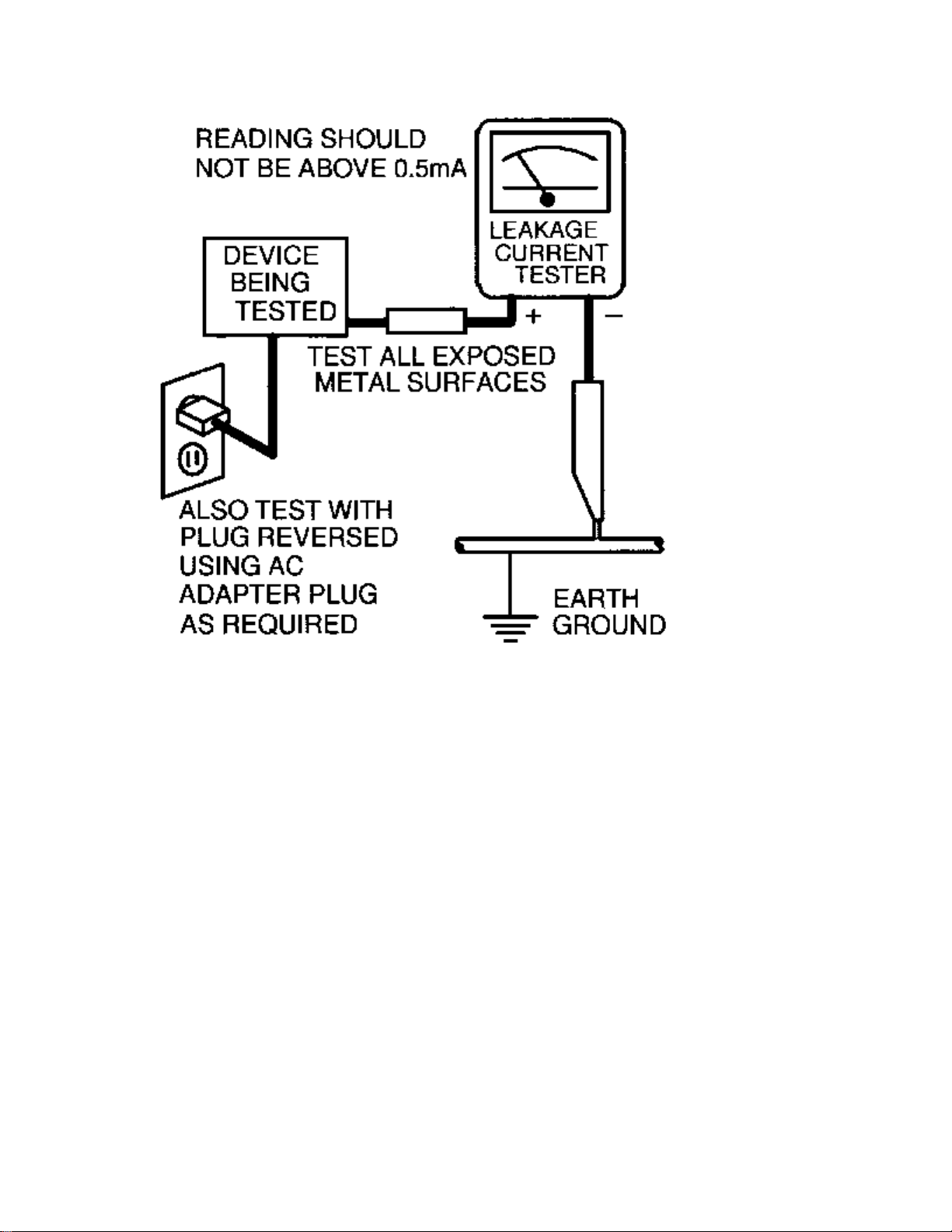
4. The potential at any point should not exceed 0.75 volts. A leakage current tester may be used to make
this test; leakage current must not exceed 0.5mA. If a measurement is outside of the specified limits,
there is a possibility of shock hazard. The receiver should be repaired and rechecked before returning it
to the customer.
5. Repeat the above procedure with the ac plug reversed. (Note: An ac adapter is necessary when a
polarized plug is used. Do not defeat the polarizing feature of the plug.)
OR
With the instrument completely reassembled, plug the ac line cord directly into a 120Vac outlet. (Do not
use an isolation transformer during this test.) Use a leakage current tester or a metering system that
complies with American National Standards Institute (ANSI) C101.1 Leakage Current for Appliances and
Underwriters Laboratories (UL) 1410, (50.7). With the instrument ac switch first in the on position and
then in the off position, measure from a known earth ground (metal water pipe, conduit, etc.) to all exposed
metal parts of the instrument (antennas, handle brackets, metal cabinet, screw heads, metallic overlays,
control shafts, etc.), especially any exposed metal parts that offer an electrical return path to the chassis.
Any current measured must not exceed 0.5mA. Reverse the instrument power cord plug in the outlet and
repeat the test. See the graphic below.
Page 5
Page 6

TV SAFETY NOTES
SAFETY CHECKS
After the original service problem has been corrected, a complete safety check should be made. Be sure to
check over the entire set, not just the areas where you have worked. Some previous servicer may have left
an unsafe condition, which could be unknowingly passed on to your customer. Be sure to check all of the
following:
Fire and Shock Hazard
Implosion
X-Radiation
Leakage Current Cold Check
Leakage Current Hot Check
Picture Tube Replacement
Parts Replacement
WARNING: Before removing the CRT anode cap, turn the unit OFF and short the HIGH VOLTAGE to
the CRT DAG ground.
SERVICE NOTE: The CRT DAG is not at chassis ground.
IMPLOSION
1. All picture tubes used in current model receivers are equipped with an integral implosion system.
Care should always be used, and safety glasses worn, whenever handling any picture tube. Avoid
scratching or otherwise damaging the picture tube during installation.
2. Use only replacement tubes specified by the manufacturer.
X-RADIATION
1. Be sure procedures and instructions to all your service personnel cover the subject of X-radiation.
Potential sources of X-rays in TV receivers are the picture tube and the high voltage circuits. The
basic precaution which must be exercised is to keep the high voltage at the factory recommended
level.
2. To avoid possible exposure to X-radiation and electrical shock, only the manufacturer's specified
anode connectors must be used.
3. It is essential that the service technician has an accurate HV meter available at all times. The
calibration of this meter should be checked periodically against a reference standard.
4. When the HV circuitry is operating properly there is no possibility of an X-radiation problem. High
voltage should always be kept at the manufacturer's rated value - no higher - for optimum
performance. Every time a color set is serviced, the brightness should be run up and down while
monitoring the HV with a meter to be certain that the HV is regulated correctly and does not exceed
the specified value. We suggest that you and your technicians review test procedures so that HV and
HV regulation are always checked as a standard servicing procedure, and the reason for this prudent
routine is clearly understood by everyone. It is important to use an accurate and reliable HV meter. It
is recommended that the HV reading be recorded on each customer's invoice, which will
demonstrate a proper concern for the customer's safety.
Page 7

5. When troubleshooting and making test measurements in a receiver with a problem of excessive high
voltage, reduce the line voltage by means of a Variac to bring the HV into acceptable limits while
troubleshooting. Do not operate the chassis longer than necessary to locate the cause of the excessive
HV.
6. New picture tubes are specifically designed to withstand higher operating voltages without creating
undesirable X-radiation. It is strongly recommended that any shop test fixture which is to be used
with the new higher voltage chassis be equipped with one of the new type tubes designed for this
service. Addition of a permanently connected HV meter to the shop test fixture is advisable. The
CRT types used in these new sets should never be replaced with any other types, as this may result in
excessive X-radiation.
7. It is essential to use the specified picture tube to avoid a possible X-radiation problem.
8. Most TV receivers contain some type of emergency "Hold Down" circuit to prevent HV from rising
to excessive levels in the presence of a failure mode. These various circuits should be understood by
all technicians servicing them, especially since many hold down circuits are inoperative as long as
the receiver performs normally.
PICTURE TUBE REPLACEMENT
The primary source of X-radiation in this television receiver is the picture tube. The picture tube
utilized in this chassis is specially constructed to limit X-radiation emissions. For continued Xradiation protection, the replacement tube must be the same type as the original, including suffix letter,
or a Philips approved type.
PARTS REPLACEMENT
Many electrical and mechanical parts in Philips television sets have special safety related
characteristics. These characteristics are often not evident from visual inspection nor can the protection
afforded by them necessarily be obtained by using replacement components rated for higher voltage,
wattage, etc. The use of a substitute part which does not have the same safety characteristics as the
Philips recommended replacement part shown in this service manual may create shock, fire, or other
hazards.
PRODUCT SAFETY GUIDELINES FOR ALL PRODUCTS
CAUTION: Do not modify any circuit. Service work should be performed only after you are thoroughly
familiar with all of the following safety checks. Risk of potential hazards and injury to the user increases if
safety checks are not adhered to.
USE A SEPARATE ISOLATION TRANSFORMER FOR THIS UNIT WHEN SERVICING.
Page 8

PREVENTION OF ELECTROSTATIC DISCHARGE (ESD)
Some semiconductor solid state devices can be damaged easily by static electricity. Such components
commonly are called Electrostatically Sensitive (ES) Devices, Examples of typical ES devices are
integrated circuits and some field-effect transistors and semiconductor "chip" components. The following
techniques should be used to help reduce the incidence of component damage caused by electrostatic
discharge (ESD).
1. Immediately before handling any semiconductor component or semiconductor-equipped assembly, drain
off any ESD on your body by touching a known earth ground. Alternatively, obtain and wear a
commercially available discharging ESD wrist strap, which should be removed for potential shock
reasons prior to applying power to the unit under test.
2. After removing an electrical assembly equipped with ES devices, place the assembly on a conductive
surface such as aluminum foil, to prevent electrostatic charge buildup or exposure of the assembly.
3. Use only a grounded-tip soldering iron to solder or unsolder ES devices.
4. Use only an anti-static solder removal device. Some solder removal devices not classified as "antistatic
(ESD protected)" can generate an electrical charge sufficient to damage ES devices.
5. Do not use Freon propelled chemicals. These can generate electrical charges sufficient to damage ES
devices.
6. Do not remove a replacement ES device from its protective package until immediately before you are
ready to install it (most replacement ES devices are packaged with leads electrically shorted together by
conductive foam, aluminum foil or comparable conductive material).
7. Immediately before removing the protective material from the leads of a replacement ES device, touch
the protective material to the chassis or circuit assembly into which the device will be installed.
CAUTION: Be sure no power is applied to the chassis or circuit and observe all other safety precautions.
8. Minimize bodily motions when handling unpackaged replacement ES devices. (Otherwise harmless
motion such as the brushing together of your clothes fabric or the lifting of your feet from a carpeted
floor can generate static electricity (ESD) sufficient to damage an ES device.)
NOTE to CATV system Installer:
This reminder is provided to call the CATV system installer's attention to article 820-22 of the NEC that
provides guidelines for proper grounding and, in particular, specifies that the cable ground shall be
connected to the grounding system of the building, as close to the point of cable entry as practical.
Page 9

PRACTICAL SERVICE PRECAUTIONS
IT MAKES SENSE TO AVOID EXPOSURE TO ELECTRICAL SHOCK. While some sources are
expected to have a possible dangerous impact, others of quite high potential are of limited current and are
sometimes held in less regard.
ALWAYS RESPECT VOLTAGES. While some may not be dangerous in themselves, they can cause
unexpected reactions – reactions that are best avoided. Before reaching into the powered color TV set, it is
best to test the high voltage insulation. It is easy to do, and is just a good service precaution.
BEFORE POWERING UP THE TV WITH THE BACK OFF (or on a test fixture), attach a clip lead to
the CRT DAG ground and to a screwdriver blade that has a well insulated handle. After the TV is powered
on and high voltage has developed, probe the anode lead with the blade, starting at the bottom of the High
Voltage Transformer (flyback – IFT). Move the blade to within two inches of the connector of the CRT. IF
THERE IS AN ARC, YOU FOUND IT THE EASY WAY, WITHOUT GETTING A SHOCK! If
there is an arc to the screwdriver blade, replace the High Voltage Transformer or the lead, (if removable)
whichever is causing the problem.
PICTURE TUBE REPLACEMENT PROCEDURE
Note: a. Two (2) people are required to handle this picture tube.
b. Safety Glasses must be worn during this procedure or whenever directly handling a picture tube.
c. Take care in each step not to damage the CRT or the cabinet.
1. Remove the Chassis and the CRT Socket Board Module from the cabinet.
2. A furniture pad or blanket should be positioned on the floor to support only the CRT Face. This pad or
blanket should be high enough to keep the CRT Face approximately 12 to 14 inches off the floor.
3. Using two people, place the cabinet in a front down position with the CRT Face on the pad or blanket.
4. Place padded blocks under each corner of the cabinet to keep it from rocking.
5. Remove the four screws, at the corners of the CRT.
6. With two people lowering the cabinet to the floor, leave the CRT elevated by the pad or blanket.
Note: Take care not to grasp the neck of the CRT during this procedure, as it is extremely fragile.
7. Two (2) people may then lift the CRT from the cabinet.
8. Remove the degaussing coil from the defective CRT and mount on the replacement. Take care to
maintain the exact shape and fit.
To install the new CRT, reverse steps 1 to 7.
Page 10

Technical Specifications, Connections and Chassis Overview
:
:
:
:
:
:
:
:
Technical Specifications
Reception
Feature Data
Tuning system
Color systems
Sound systems
A/V connections
: PLL
: NTSC M (3.58 - 4.5)
: BTSC DBX
: DVD (1fH YUV)
480p
1080i
NTSC playback
VGA
SVGA
XGA
MAC II
Channel selections
Aerial input
: 125 channels
Full cable
: 75 Ohm, F-type
Miscellaneous
Feature Data
Page 11

Mains voltage
: 85 - 264 V
Mains frequency
Ambient temperature
Maximum humidity
Power dissipation
Standby Power dissipation
Weight
Dimensions (WxHxD)
: 50/60 Hz
: + 5 to + 45 deg. C
: 90% R.H.
: < 34 W
: < 2 W
: 4 kg
: 435 x 100 x 330 mm
Page 12
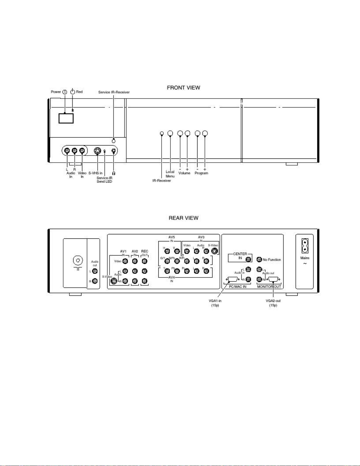
Connections
Figure: Front and rear connections
Page 13

Front Connections
Audio/Video - In
Connector Kind Value Symbol
1
2
3
4
SVHS - In
Connector Kind Value Symbol
1
2
3
Audio - L
Audio - R
CVBS
Headphone
Y
C
Y
0.5 Vrms / 10 kOhm
0.5 Vrms / 10 kOhm
1 Vpp / 75 Ohm
32 - 600 Ohm / 10 mW
Ground
Ground
1 Vpp / 75 Ohm
jq
jq
jq
ot
H
H
j
4
C
0.3 Vpp / 75 Ohm
j
Page 14

Rear Connections
Aerial - In
Connector Kind Value Symbol
1
Audio - Out (Constant Level)
Connector Kind Value Symbol
1
2
AV1 - In (SVHS, CVBS, Audio)
Connector Kind Value Symbol
1
F-type
Audio - L
Audio - R
Y
Coax, 75 Ohm
0.5 Vrms / 1 kOhm
0.5 Vrms / 1 kOhm
Ground
D
kq
kq
H
2
3
4
5
6
7
C
Y
C
CVBS
Audio - L
Audio - R
Ground
1 Vpp / 75 Ohm
0.3 Vpp / 75 Ohm
1 Vpp / 75 Ohm
0.5 Vrms / 1 kOhm
0.5 Vrms / 1 kOhm
H
j
j
jq
jq
jq
Page 15

AV2 - In (CVBS, Audio)
Connector Kind Value Symbol
1
2
3
REC - Out (CVBS, Audio)
Connector Kind Value Symbol
1
2
3
AV3 - In (CVBS, Audio, SVHS)
CVBS
Audio - L
Audio - R
CVBS
Audio - L
Audio - R
1 Vpp / 75 Ohm
0.5 Vrms / 1 kOhm
0.5 Vrms / 1 kOhm
1 Vpp / 75 Ohm
0.5 Vrms / 1 kOhm
0.5 Vrms / 1 kOhm
jq
jq
jq
kq
kq
kq
Connector Kind Value Symbol
1
2
3
4
5
6
7
CVBS
Audio - L
Audio - R
Y
C
Y
C
1 Vpp / 75 Ohm
0.5 Vrms / 1 kOhm
0.5 Vrms / 1 kOhm
Ground
Ground
1 Vpp / 75 Ohm
0.3 Vpp / 75 Ohm
jq
jq
jq
H
H
j
j
Page 16

AV4 - In (YUV, Audio)
Connector Kind Value Symbol
1
2
3
4
5
AV5 – In (RGB, YUV, Audio)
Connector Kind Value Symbol
1
2
Y
Pb
Pr
Audio - L
Audio - R
H
V
1 Vpp / 75 Ohm
0.7 Vpp / 75 Ohm
0.7 Vpp / 75 Ohm
0.5 Vrms / 1 kOhm
0.5 Vrms / 1 kOhm
1 Vpp / 75 Ohm
1 Vpp / 75 Ohm
jq
jq
jq
jq
jq
jq
jq
3
4
5
6
7
G/Y
B/Pb
R/Pr
Audio - L
Audio - R
1 Vpp / 75 Ohm
0.7 Vpp / 75 Ohm
0.7 Vpp / 75 Ohm
0.5 Vrms / 1 kOhm
0.5 Vrms / 1 kOhm
jq
jq
jq
jq
jq
Page 17
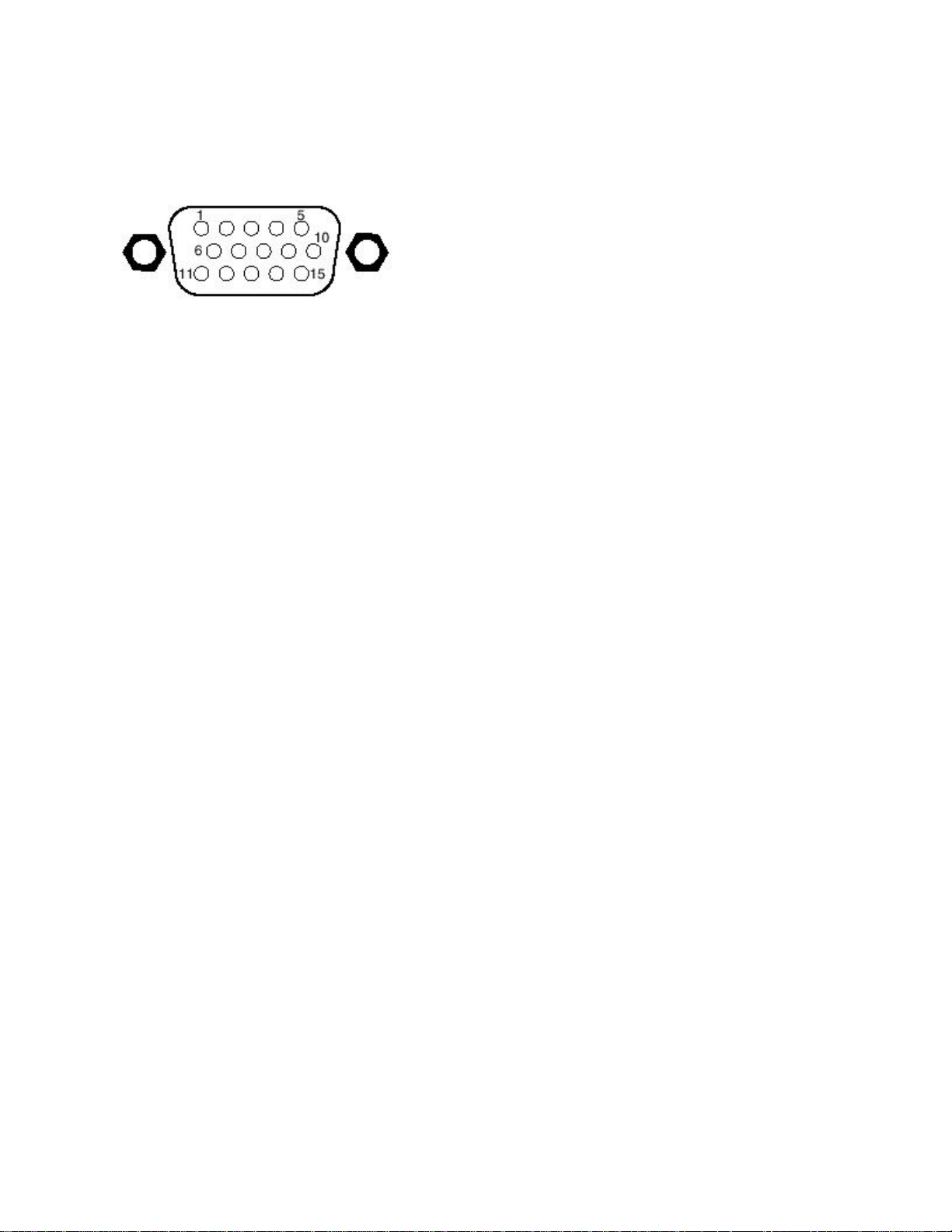
VGA1- in
Figure: VGA connector
Connector Kind Value Symbol
1
2
3
4
5
6
7
8
9
10
Red
Green
Blue
Red
Green
Blue
0.7 Vpp / 75 Ohm
0.7 Vpp / 75 Ohm
0.7 Vpp / 75 Ohm
Ground
Ground
Ground
Ground
j
j
j
H
H
H
H
11
12
13
14
15
H-sync
V-sync
j
j
Page 18

Audio - In (VGA1), Center - In
Connector Kind Value Symbol
1
2
3
Audio - Out (VGA2), RC - In
Connector Kind Value Symbol
1
2
Audio - R
Center
Audio - L
Audio - R
Audio - L
0.5 Vrms / 10 kOhm
0.5 Vrms / 10 kOhm
0.5 Vrms / 10 kOhm
0.5 Vrms / 10 kOhm
0.5 Vrms / 10 kOhm
jq
jq
jq
kq
kq
Page 19
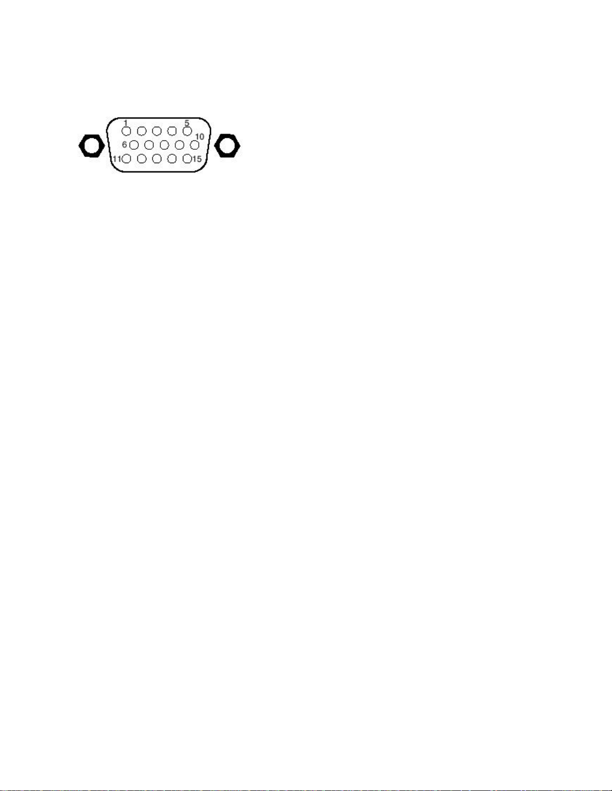
VGA2 - out
Figure: VGA connector
Connector Kind Value Symbol
1
2
3
4
5
6
7
8
9
10
Red
Green
Blue
Red
Green
Blue
RC
0.7 Vpp / 75 Ohm
0.7 Vpp / 75 Ohm
0.7 Vpp / 75 Ohm
Ground
Ground
Ground
Ground
Ground
k
k
k
H
H
H
H
j
H
11
12
13
14
15
CONFIG_IDENT
UART - TXD
H-sync
V-sync
UART - RXD
k
k
k
k
k
Page 20
Mechanical instructions
Index of this chapter:
1. Disassembly.
2. Service positions.
3. Reassembly.
Note: Figures below can deviate slightly from the actual product, due to different set
designs.
Disassembly
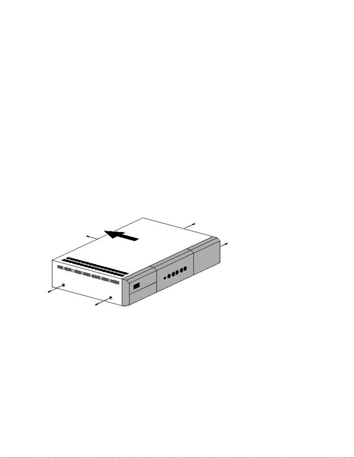
Figure: Top cover removal
1. Unplug the AC power cord first, for safety reasons.
2. Remove all screws on the metal top cover.
3. Remove the metal top cover.
Page 21
Service positions
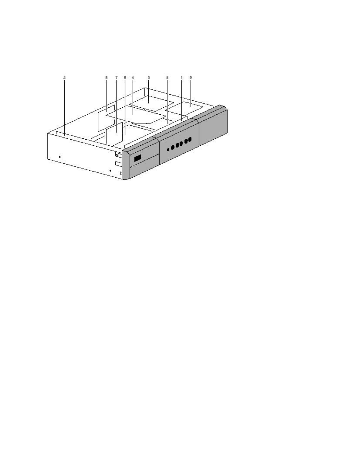
Figure: Panel overview
1. Front I/O Panel.
2. Power Supply Panel.
3. Double Window Panel.
4. Feature Box.
5. Small Signal Panel.
6. Audio Video Interface Panel.
7. Down Scaler Panel.
8. High Definition Connector Panel.
9. 3D Comb Panel.
Page 22
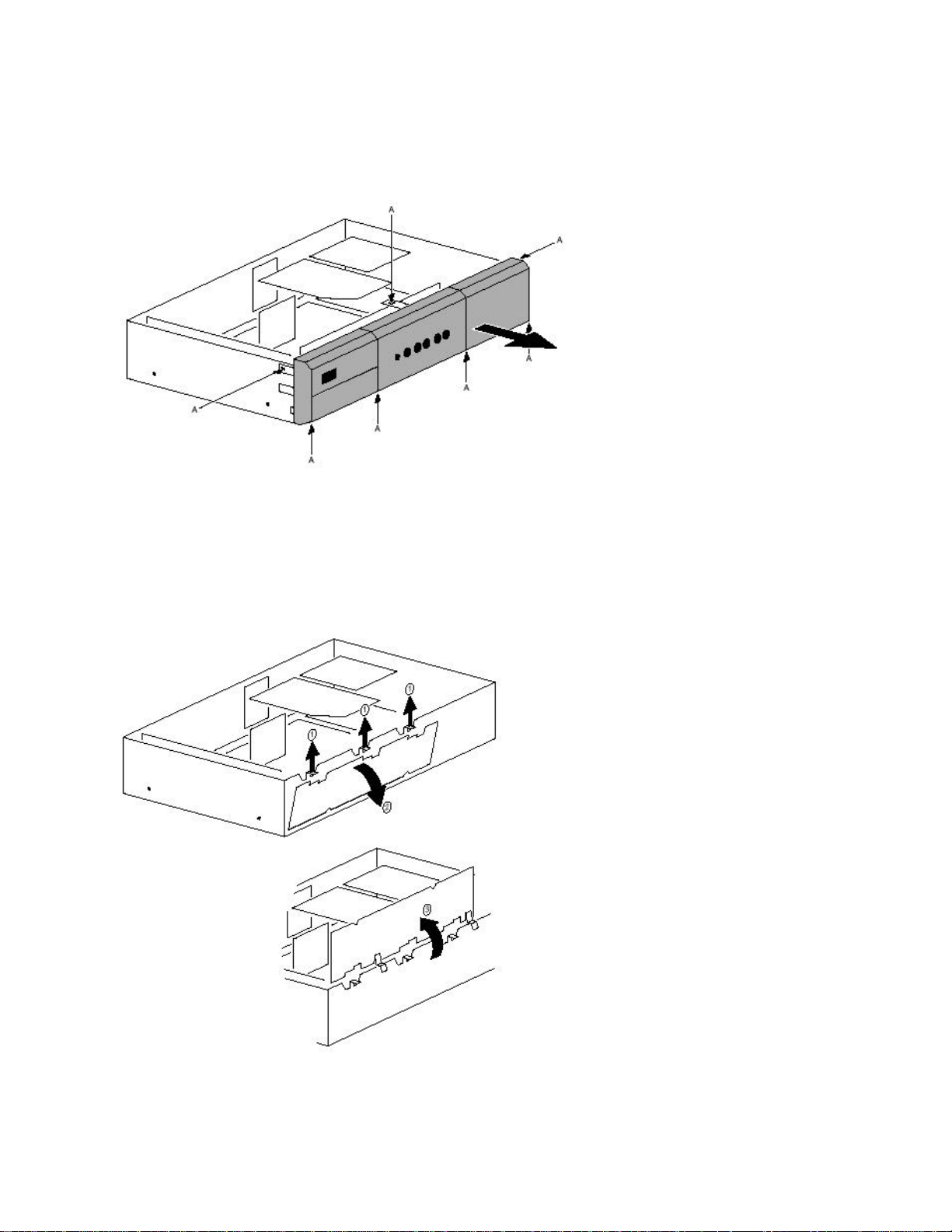
Front I/O Panel
Figure: Front cover removal
1. Pull the lugs [A] slightly aside.
2. Pull the front panel in the direction of the arrow.
Figure: Service position Front I/O panel
Page 23
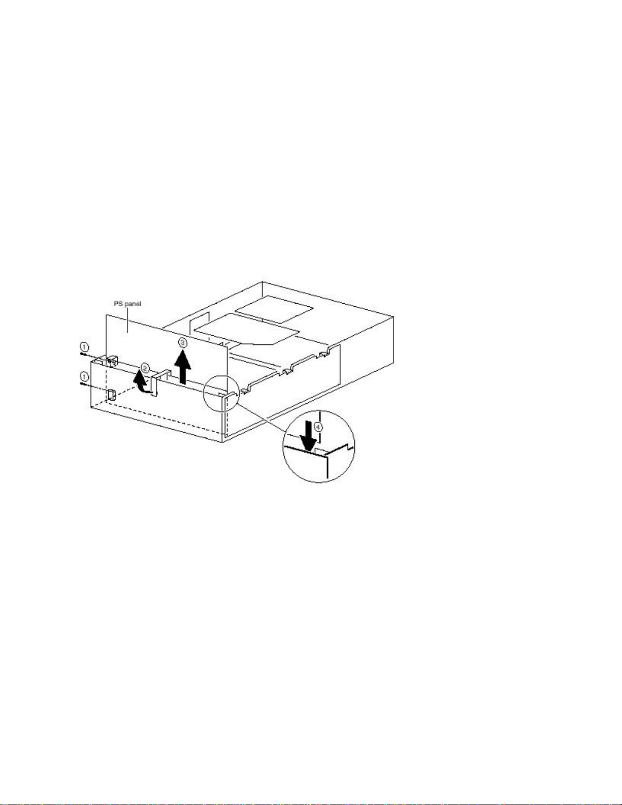
1. Lift the clamps to release the panel [1].
2. Take the panel out of the receiver box [2].
3. Place the panel on top of the housing [3].
Note: Be sure to keep track of the three "copper" grounding clips; they can be lost very
easily.
Power Supply Panel
Figure: Service position Power Supply panel
1. Remove the front panel (see above).
2. Remove the screws [1].
3. Remove the bracket [2] (if present).
4. Pull the Power Supply panel out of the receiver box [3].
5. Place the Power Supply panel in the small slots on the edges of the top of the
housing [4].
6. Warning: Beware of the live voltages on this board during operation!
Page 24
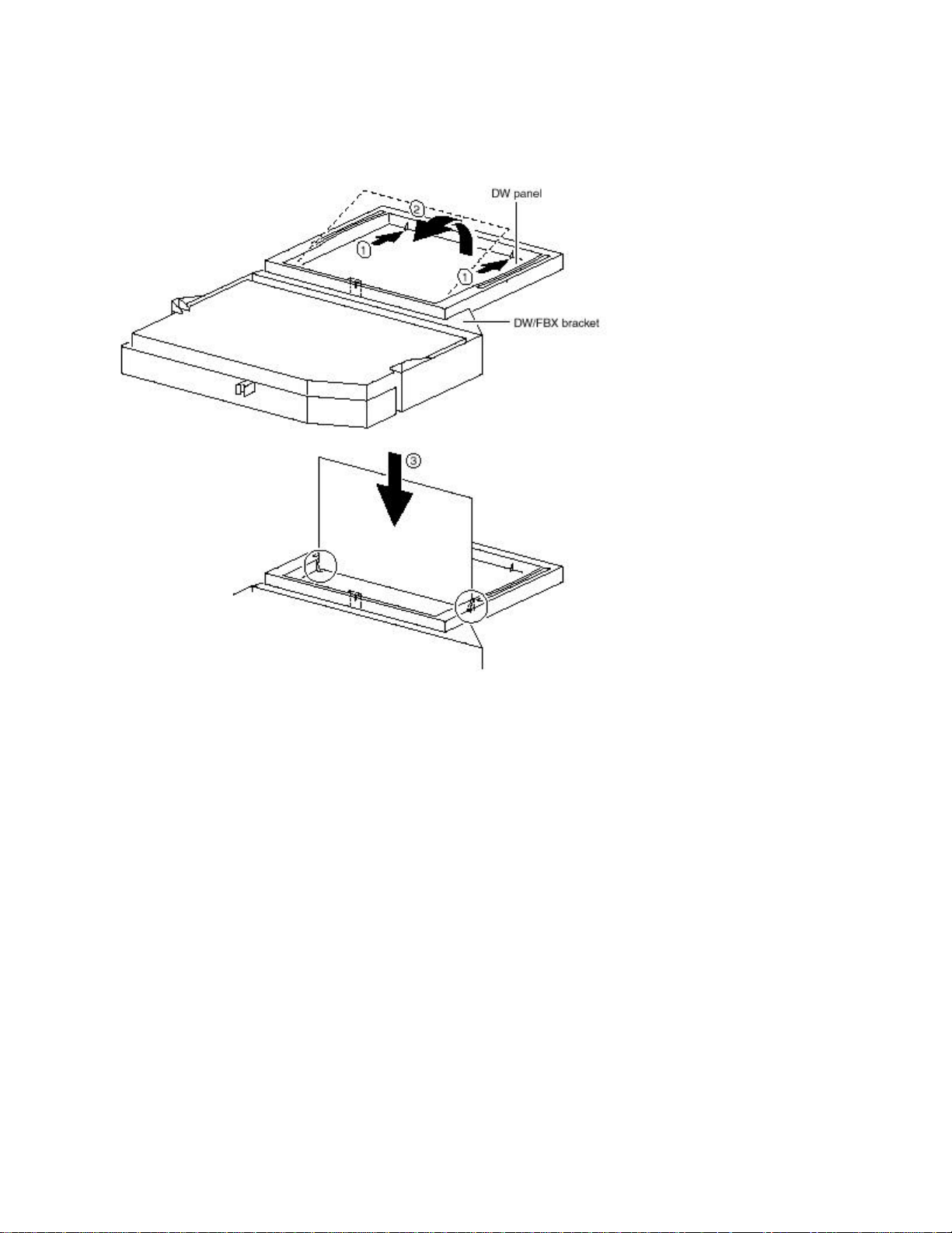
Double Window Panel
Figure: Service position Double Window panel
When the metal top cover is removed, the Double Window panel is accessible. For the
service position:
Release the clamps [1].
Some of the cables must be temporarily disconnected to place the Double Window
panel in the service position.
Push the panel gently up and out of its bracket [2].
Place the panel in the Double Window / Feature Box bracket [3].
Reconnect the cables.
Page 25
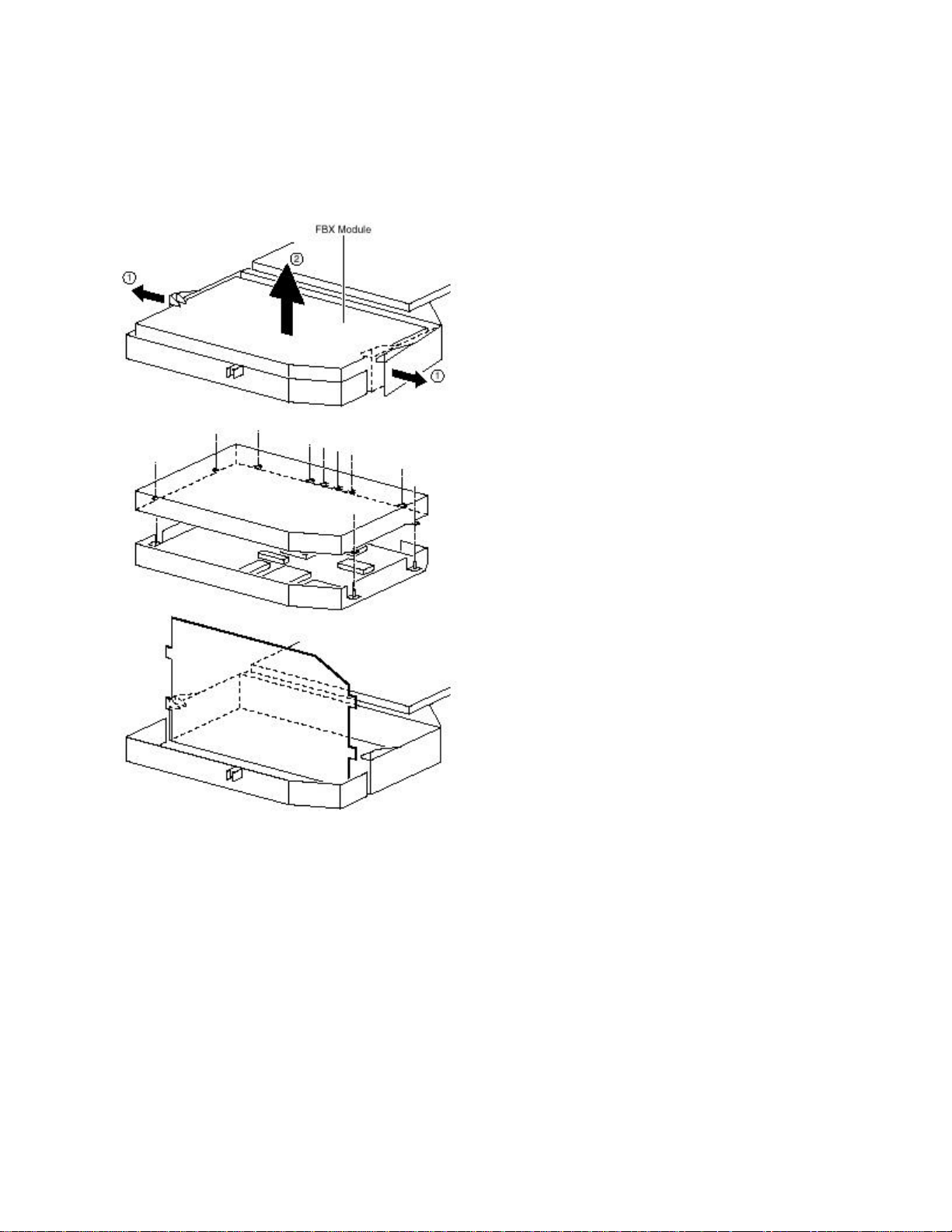
Feature Box
Figure: Service position Feature Box panel
1. Pull the clamps aside [1], and take out the Feature Box module [2].
2. Disconnect the cables from the Feature Box module.
3. Remove the shielding of the Feature Box module: to do this, you must desolder
the lugs on the shielding.
4. Remove the Feature Box panel from the Feature Box module.
5. Place the Feature Box panel in the Feature Box bracket.
6. Reconnect the cables.
Page 26
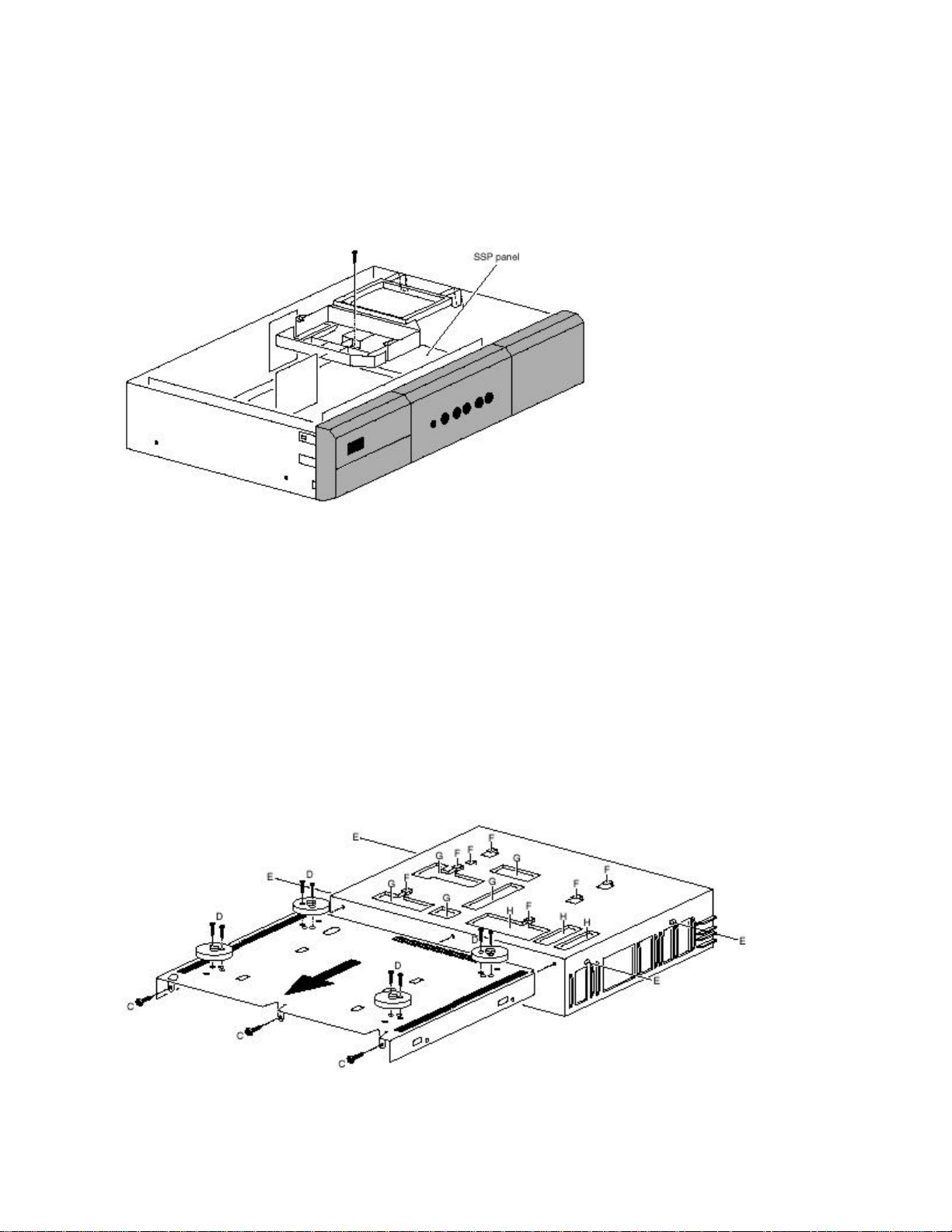
Small Signal Panel
If the Double Window / Feature Box bracket is removed, the component side of the
Small Signal Panel is accessible.
Figure: Removal of the Double Window / Feature Box bracket
1. Remove the screw.
2. Release the clamps, and remove the Feature Box panel (see paragraph 4.2.4).
3. Replace the Feature Box and Double Window panels without the bracket.
Note: Place a piece of cardboard between the Double Window and Feature Box panels
and all other parts and/or components, to prevent short circuiting.
Figure: Removal of bottom cover plate
Page 27

To access the copper side of the Small Signal Panel, you have to remove the metal
bottom cover plate:
1. Turn the receiver box upside down.
2. Remove the screws [C] at the rear.
3. Remove the screws [D] that hold the four feet. Then remove the feet.
4. Pull the metal bottom plate backwards (lift it over the studs [E]). Be aware of the
hooks [F] on the frame.
Audio Video Interface Panel
If the metal top cover is removed, the copper side of this panel is accessible.
Down Scaler Panel
If the metal top cover is removed, the copper side of this panel is accessible.
High Definition Connector Panel
There is no service position for this panel. The best way to perform measurements on
this panel is to remove the Double Window / Feature Box bracket (see above). After
this, the component side of this (single-sided) panel is accessible.
To remove the panel, unscrew the four screws that hold it (on the inside of the set).
Page 28

3D Comb Panel
1. Remove the screws.
2. Lift the bracket up (this requires some force).
3. Most of the test points are now accesible.
If it is necessary, you can remove the panel from its bracket. To do this, release the four
clamps on the larger panel, while pushing the panels upwards. Both panels will slide out
of the bracket.
Reassembly
• To reassemble the set, perform the disassembly processes in reverse order.
• Before replacing the top cover, return all cables to their original positions
Page 29

Service Modes, Error Codes, and Fault Finding
Index of this section:
1. Test Points
2. Service Modes
3. Problems and Problem Solving Tips (related to CSM).
4. ComPair
5. Error Codes
6. Protections
7. Repair Tips
Supporting Overviews
• Power lines overview
• I2C-IC overview
• AV interface panel (AV)
• Power Supply Panel (PS)
• FDS module (M) (copper side)
• FDS module (M) (component side)
• FBX panel (L)
• Small signal panel (K)
• Layout A/V Interface panel (bottom side)
• Wiring Diagram
Page 30

Test Points
General
Perform measurements under the following conditions:
• Set in Service Default Mode.
• Video: Color bar signal, received via the internal tuner.
• Audio: 3 kHz left, 1 kHz right.
Exceptions (when using external sources):
• Set in Service Default Mode.
• Video: If using a DVD player, use a "live" picture; if using a VGA source, use a
picture of your choosing.
• Audio: A service generator, or the audio from the DVD player or VGA source, can
be used.
Waveforms
The chassis is equipped with test points printed on the circuit board assemblies. Test
points are displayed in two different ways:
The old method, still in use for re-used circuits (like the Small Signal Panel, the Double
Window Panel, and the Feature Box), refers to the functional blocks. The test points
have names starting with I for IF, S for sound, etc. The numbering is in a logical
sequence for diagnostics.
The new method, used for new circuits, uses service test points that are recognizable as
tagged Fxxx points. With this method, factory test points are published (F-points are functional
test points, I-points are test points for in-circuit testers in the factory. All these test points are on
the copper side. When the test point is a service test point, it is tagged for recognition.
Page 31

Not all test points have been measured, but they can serve as identification names in
Service communication (for example, ComPair fault find trees, Force32 files).
In the following cases, there will be no waveform:
• When a Vdc voltage is displayed in the diagrams, or when the waveform does
not have an additional value.
• When the sources are not easy accessible for the Service engineer (for example,
HD source, VGA source).
• External AV inputs are not measured, since the waveform is equal to the source
(dependent of load resistor matching).
DC voltages
The DC voltages are measured at practically all semiconductor pins. These values are
displayed in the circuit diagrams. If a DC value is displayed between brackets then this
value is measured in "standby" mode.
Note: DC voltages are also measured on the connectors.
Service Modes
Service Default Mode (SDM) and Service Alignment Mode (SAM) offer several features
for the service technician, while the Customer Service Mode (CSM) is used for
communication between the servicer and the customer.
There is also the option of using ComPair, a hardware interface between a computer
(see requirements) and the FTV chassis. It offers the ability of structured
troubleshooting, a test pattern generation, error code reading, software version readout,
and software upgrading. (Software upgrading is not available for all chassis)
Minimum requirements for ComPair: a Pentium Processor, Windows
9x/NT/2000/XP/ME, and a CD-ROM drive (see "ComPair" section).
Page 32

Service Default Mode (SDM)
Purpose
• To create a pre-defined setting to get the same measurement results as given in
this manual.
• To override SW protections (only when SDM is entered via the “service pins” on
SSP connector 0356).
• To start the "blinking LED" procedure.
Specifications
• Tuning frequency: 61.25 MHz (Channel 3).
• Color system: NTSC.
• All picture settings at 50 % (brightness, color, contrast).
• Bass, treble and balance at 50 %; volume at 25 %.
• All service-unfriendly modes (if present) are disabled. The service unfriendly
modes include:
§ Sleep timer
§ Smart modes
§ On Timer
§ Child lock
§ Black mute
Page 33

How to enter SDM
To enter SDM, use one of the following methods:
• Press the following key sequence on the remote control transmitter:
• 0-6-2-5-9-6-MENU Do not allow the display to time out between entries while
keying the sequence.
• Short pins 2 and 3 on connector 0356 of the SSP while the set is in the normal
operation mode. Caution: Entering SDM by this method will override all
processor-controlled protections. When doing this, the service technician must
know exactly what he is doing, as this could damage the set.
• Use the Dealer Service Tool (DST) emulation feature of ComPair.
After entering SDM, a blank screen is visible, with "Service Default" in the upper part for
recognition. The “blinking LED” procedure is started and will indicate any possible errors
via the front LED.
How to navigate in SDM
To toggle to the SAM mode, press the following key sequence on the remote control
transmitter:
0-6-2-5-9-6-OSD (i+)
Do not allow the display to time out between entries while keying the sequence.
How to exit SDM
Switch the set to "Standby" by pressing the POWER button on the remote control
transmitter (if you switch the set "OFF" by disconnecting the AC power cable, the set
will remain in SDM when AC power is reapplied).
Page 34

Service Alignment Mode (SAM)
Purpose
• To perform (software) alignments.
• To change the option settings.
• Easy identification of the software version.
• To view operational hours.
• To display (or clear) the error code buffer.
• To give the service technician the possibility (through a special sequence of
navigating and selecting) to diagnose F21R problems with a standard PC
monitor.
Specifications
• Software version of main processor.
• Operational hours counter.
• Dealer options.
• Service options.
• Error buffer reading and erasing.
• Alignments.
• Functional test.
Page 35
How to enter SAM
Use one of the following methods:
• Press the following key sequence on the remote control transmitter:
• 0-6-2-5-9-6-OSD (i+)
• Do not allow the display to time out between entries while keying the sequence.
• Short jumpers 1 and 2 of connector 0356 on the SSP.
• Use the "Align" key of the Dealer Service Tool (DST) emulation feature of
ComPair.
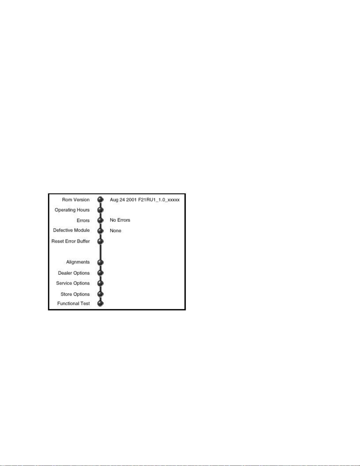
After entering SAM, the following screen is visible:
Figure: SAM Menu
• "Rom Version" Gives the software date and version of the ROM ( Example: Sep
10 2001 AAAABC_X.Y_xxxxx).
§ AAAA = the chassis name (F21R= Flat TV 2.1 Receiver box).
§ B = the region (E= Europe, A= Asia Pacific, U= NAFTA, L= LATAM or G=
Global).
Page 36

§ C = the language cluster (1= English).
§ X = the main software version number.
§ Y = the sub software version number.
§ xxxxx = the last five digits of the 12nc code.
• "Operation Hours" The accumulated total of operation hours of the Receiver box.
Every time the Receiver box is switched on, 0.5 hour is added to the operation
hours counter.
• "Errors" Room for a maximum of 10 errors. The most recent error is displayed at
the upper left position. For an explanation of the errors, see the error code table
in the "Error Codes" section.
• "Defective Module" The module that generates an error is displayed here. If there
are multiple errors in the buffer that have not all been generated by a single
module, there is probably another defect. In that situation, the message
"Unknown" will then be displayed here. If there are no errors, "None" is
displayed.
• "Reset Error Buffer" Erases the contents of the error buffer. Press "OK" on the
remote control transmitter to do this; the error buffer is cleared.
• "Alignments" Navigation by sub menus to service alignment items. The details of
these alignments are explained in the "Electrical Alignments" section.
• "Dealer Options" Controls the demonstration modes used by dealers for display
purposes.
• "Service Options" In this sub menu, the options can be set. The quickest method
to do this is through HW option number entry.
• "Store Options" Service options must be stored here. Note: Without storing, no
changes made to the options will be recorded. The servicer must remember to
store all changes before exiting SAM for those changes to take effect.
• "Functional Test" Activate this test by pressing the "OK" key on the remote
control transmitter. Eventual errors are displayed in the error buffer. The error
buffer is not erased, although it looks that way. By exiting SAM and then entering
SAM again, you will see the error buffer still contains the previous contents.
Page 37

How to navigate in SAM
Use one of the following methods:
• In SAM, select menu items with the "Cursor Up/Down" keys on the remote
control transmitter. The selected “ball” item is highlighted and becomes a “puck”
(blue becomes yellow). When not all menu items fit on the screen, this is shown
by two "ball" figures overlapping. Use the " Cursor Up/Down " keys to display the
next / previous menu item(s).
• With the "Cursor Left/Right" keys, it is possible to:
§ (De)activate the selected menu item.
§ Change the parameter of the selected menu item (some times through a
"slider" entry)
§ Activate the selected submenu.
• To toggle to the SDM mode, press the following key sequence on the remote
control transmitter:
• 0-6-2-5-9-6-MENU
• Do not allow the display to time out between entries while keying the sequence.
Note: SAM is exited when the MENU button on the remote control transmitter is pressed
once. This has changed from MG sets with the "old" user interface. If SAM is exited
accidentally, you have to enter the SAM mode again to perform SAM alignments and
adjustments.
How to exit SAM
To exit SAM, press the MENU button on the remote control transmitter once.
Page 38

Customer Service Mode (CSM)
Purpose
The Customer Service Mode shows error codes and information on the Flat TV
operation settings. The servicer can instruct the customer to enter CSM by telephone
and read off the information displayed. This helps the servicer to diagnose problems
and failures in the Flat TV set before making a service call.
The CSM is a read-only mode; therefore, modifications are not possible in this mode.
How to enter CSM
To enter CSM, use one of the following methods:
• Press the MUTE button on the remote control transmitter and the MENU button
on the local keyboard simultaneously for at least four seconds.
• An alternative CSM entry method is to press the following key sequence on the
remote control transmitter:
• 1-2-3-6-5-4
• Do not allow the display to time out between entries while keying the sequence.
• The disadvantage to using this method to enter CSM is that the selected source
is changed, due to the key sequence. Therefore, the first method is preferred.
Upon entering the Customer Service Mode, the following screen will appear:
Customer Service Menu 1
• "Set Type" This allows the customer to view the type number of the Receiver
box, without looking at the bottom of this box. This information can be very
helpful when talking with the service technician.
• "SW version" Indicates the software version (AAAABCX.Y) of the box. See
explanation in "SAM" section.
Page 39

• "Code 1" Gives the last five errors of the error buffer. As soon as the built-in
diagnosis software has detected an error, the buffer is adapted. If there are no
errors, the text "0" is displayed.
• "Code 2" Gives the first five errors of the error buffer. As soon as the built-in
diagnosis software has detected an error, the buffer is adapted. The most recent
error is displayed on the left most position of the Code 2 line. Each error code is
displayed as a 3-digit number. When less than 10 errors occur, the rest of the
line(s) is (are) empty. If there are no errors, the text "0" is displayed. See the
"Error Codes" section for a description of the error codes. Service Tip: When a
group of adjacent errors has a specific color, this means they have occurred in
the same time window. This gives service technicians additional information.
• "Volume" Shows the last status of the volume, as set by the customer. The
parameter can vary from 0 (minimum) to 100 (maximum). Volume parameters
can be changed by using the volume key on the remote control transmitter.
• "Brightness" Gives the last status of the brightness, as set by the customer. The
parameter can vary from 0 (minimum) to 100 (maximum). The brightness
parameter can be changed by using the "cursor left" and "cursor right" keys on
the remote control transmitter after pressing the "menu" button and navigating to
"picture" and setting "brightness."
• "Contrast" Gives the last status of the contrast, as set by the customer. The
parameter can vary from 0 (minimum) to 100 (maximum). Contrast parameters
can be changed by using the "cursor left" and "cursor right" keys on the remote
control transmitter after pressing the "menu" button and navigating to "picture"
and setting "contrast."
• "Color" Gives the last status of the color saturation, as set by the customer. The
parameter can vary from 0 (minimum) to 100 (maximum). Color parameters can
be changed by using the "cursor left" and "cursor right" keys on the remote
control transmitter after pressing the "menu" button and navigating to "picture"
and setting "color."
Page 40

• "Hue" Gives the last status of the color saturation, as set by the customer. The
parameter can vary from -50 (minimum) to 50 (maximum). Hue parameters can
be changed by using the "cursor left" and "cursor right" keys on the remote
control transmitter after pressing the "menu" button and navigating to "picture"
and setting "hue."
• "Sharpness" Gives the sharpness parameter, as set by the user. It can vary from
0 (minimum) to 7 (maximum). A noisy picture may result if there is a bad antenna
signal, or the parameter of sharpness is set too high. Sharpness parameters can
be changed by using the "cursor left" and "cursor right" keys on the remote
control transmitter after pressing the "menu" button and navigating to "picture"
and setting "sharpness."
The next Customer Service Mode screen can be selected by pressing the "cursor down"
key on the remote control transmitter. To return to the previous Customer Service Mode
screen, press the "cursor up" key on the remote control transmitter (there are 4 CSM
menu screens).
Customer Service Mode Screen 2
• "Headphone Volume" Gives the last status of the headphone volume, as set by
the customer. The parameter can vary from 0 (minimum) to 100 (maximum).
Headphone volume parameters can be changed by using the "cursor left" and
"cursor right" keys on the remote control transmitter after pressing the "menu"
button and navigating to "sound" and setting "headphone volume."
• "Center Mode" Indicates the loudspeaker configuration of the monitor. If it is set
to "On," then the internal speakers both produce center sound (from the "center
input" input jack on the back of the set). If it is set to "Off," the speakers produce
left and right sound. This parameter can be changed by using the "cursor left"
and "cursor right" keys on the remote control transmitter after pressing the
Page 41

"menu" button and navigating to "Settings," "General" and choosing "Center
mode" = “On."
• "Sound Mode" Indicates the selected sound mode, as selected by the customer.
This can be "Stereo," or "Mono." This parameter can be changed by using the
"cursor left" and "cursor right" keys on the remote control transmitter after
pressing the "menu" button and navigating to "Settings," "General" and choosing
"Sound mode."
• "Spatial Mode" Indicates the selected sound mode, as set by the customer. This
can be set to "On" or "Off." This parameter can be changed by using the "cursor
left" and "cursor right" keys on the remote control transmitter after pressing the
"surround mode" key behind the cover of the RC. When the surround mode is
"On" (by toggling to "On" and confirming with the "OK" key) the "Spatial Mode" is
"On." When surround mode is "Off," the "Spatial Mode" should be "Off."
Therefore, if an unexpected processed sound is heard, this can be the reason.
• "Digital Natural" Indicates the digital natural motion mode selected by the
customer. This can be set to "On" or "Off." This parameter can be changed by
using the "cursor left" and "cursor right" keys on the remote control transmitter
after pressing the "menu" button and navigating to "Menu," "Picture" and
choosing "Dig natural motion."
Customer Service Mode Screen 3
• "Balance" Gives the last status of the balance, as set by the customer. The
parameter can vary from -50 (maximum left balance) to 50 (maximum right
balance). Balance parameters can be changed by using the "cursor left" and
"cursor right" keys on the remote control transmitter after pressing the "menu"
button and navigating to "sound" and setting "balance."
• "DNR" (setting of Dynamic Noise Reduction). This can be set to "Off,"
"minimum," "medium," or "maximum."
Page 42

• "Noise Figure" Gives the selected noise ratio for the selected transmitter. This
parameter can vary from 0 (good signal), to 127 (average signal), to 255 (bad
signal). Note: This measured value only has significance when the "active
control" mode is activated (this can be done by pressing the "active control" key
on your remote control transmitter).
• "Source" This can be set to "Tuner" (default), "Ext1," "Ext2," "Ext3," "Ext4,"
"Ext5," "Front," or "VGA" (not visible). Behind this source value there is an item
referring to the "quality" of the chosen source (VIDEO/STEREO, VIDEO/NICAM,
S-VIDEO/STEREO, S-VIDEO/NICAM, and RGB/STEREO). This source
parameter can be changed by using the "cursor left" and "cursor right" keys on
the remote control transmitter after pressing the "menu" button and navigating to
"Menu," "Setup," and choosing "Source." The "quality" parameter depends how
you connect your source: for example, if you connected the source by the Video
input or by the SVHS input.
• "Audio System" Gives information about the audio system of the selected
transmitter.
§ Analog Mono: Mono sound received
§ Analog Stereo: Stereo sound received
• "Tuned Bit" Gives information about the tuning method of the stored preset. If a
channel is detected by searching (manual as well as automatic installation), the
micro-search tuning algorithm is used. When a channel is identified and stored,
this will display "Yes." When you install a preset (while the channel is not being
broadcast) with "digit entry"/"fine tune," the display (after storing) will read "No." If
the channel is found later (after a successful micro-search), the tuned bit will
change to "Yes." If the tuned bit displays "No," something is wrong with the
installed preset. Please reinstall the preset.
Page 43

Customer Service Mode 4
• "33 Channel Lock" Gives the status of the general "child lock." This can be:
"Unlock," "Lock," or "Custom Lock"
• "Movie ratings lock" gives the ability to select access to individual movies based
on their MPAA ratings.
• None
• All
• NR
• G
• PG
• PG-13
• R
• NC-17
• X
• Only the "highest" value in every rating group is shown.
• "TV ratings lock" gives the setting of V-chip as selected by the customer (for
more details see DFU).
• All: no content based rating.
• No Rating
• TV-Y
• TV-Y7
• TV-Y7-FV
• TV-G
• TV-PG
• TV-PG-D
• TV-PG-L
• TV-PG-S
• TV-PG-V
• TV-PG-14
Page 44

• TV-PG-14-D
• TV-PG-14-L
• TV-PG-14-S
• TV-PG-14-V
• TV-MA
• TV-MA-L
• TV-MA-S
• TV-MA-V
• Only the "highest" value in every rating group is shown.
• "SW code 1". This code is only for Development. Do not use it.
• "SW code 2". This code is only for Development. Do not use it.
Problems and Solving Tips (Related to CSM)
Picture Problems
Note: The problems described below are related to the TV settings. The procedures to
change the parameters (or status) of the different settings are described.
Snowy/noisy picture
Check the "Noise Figure" line. If the value is 127 or higher and is also high on other
programs, check the aerial cable/aerial system.
Picture too dark
Press the "Smart Picture" button on the remote control transmitter. If the picture
improves, increase the brightness value or increase the contrast value. The new
value(s) are automatically stored for all TV channels.
Page 45

If the picture improves after entering CSM, increase the brightness value or increase the
contrast value. The new value(s) are automatically stored for all TV channels.
Check the "Brightness" and "Contrast" lines. If the value of "Brightness" is low (<15) or
the value of "Contrast" is low (<15), increase the brightness value or increase the
contrast value.
Picture too bright
Press the "Smart Picture" button on the remote control transmitter. If the picture
improves, reduce the brightness value or reduce the contrast value. The new value(s)
are automatically stored for all TV channels.
If the picture improves after entering CSM, reduce the brightness value or reduce the
contrast value. The new value(s) are automatically stored for all TV channels.
Check the "Brightness" and "Contrast" lines. If the value of "Brightness" is high (>60) or
the value of "Contrast" is high (>75), reduce the brightness value or increase the
contrast value.
Fading picture
Digital scan effect. Check the "DNR" line. The status of "DNR" is a value between 0 and
100. There is no practical way to explain the significance of this value. If the picture is
fading, adjustment of the "DNR" level may help. The "DNR" level can be adjusted by the
following navigation route: "Menu" - "Picture" - "DNR." There are four different
selectable levels.
Page 46

White line around picture elements and text
Press the "Smart Picture" button on the remote control transmitter. If the picture
improves, reduce the sharpness value. The new value(s) are automatically stored for all
TV channels.
If the picture improves after entering CSM, reduce the sharpness value. The new
value(s) are automatically stored for all TV channels.
Check the "Sharpness" line. If the value is too high, reduce the sharpness value. The
new value(s) are automatically stored for all TV channels.
Black picture and/or unstable picture
Improper signal is being received. Check the "Noise Figure" line. If the value is higher
then 127, the signal is suspect. Check your cable or aerial signal.
Black and white picture
Check the "Color" line. If the "Color" value is low (<30), increase the "Color" value. The
new value(s) are automatically stored for all TV channels.
Menu text not sharp enough
Press the "Smart Picture" button on the remote control transmitter. If the picture
improves, reduce the contrast value. The new value(s) are automatically stored for all
TV channels.
If the picture improves after entering CSM, reduce the contrast value. The new value(s)
are automatically stored for all TV channels.
Check the "Contrast" line. If this value is high (>75), reduce the contrast value.
Page 47

Sound problems (only with FTV-monitor connected)
No sound from left and right speaker.
Possible solutions:
Press the "Smart Sound" button on the remote control transmitter. If the sound
improves, raise the volume value. The new value(s) are automatically stored for all TV
channels.
If the volume is acceptable after entering CSM, increase the volume. The new value(s)
are automatically stored for all TV channels.
Check the "Volume" line. If the value is low, increase the value of "Volume." The new
value(s) are automatically stored for all TV channels.
Sound too loud from left and right speaker.
Press the "Smart Sound" button on the remote control transmitter. If the sound
improves, reduce the volume value. The new value(s) are automatically stored for all TV
channels.
If the volume is acceptable after entering CSM, decrease the volume. The new value(s)
are automatically stored for all TV channels.
Check the "Volume" line. If the value is high, reduce the value of "LS Volume." The new
value(s) are automatically stored for all TV channels.
Page 48

ComPair
Introduction
ComPair (Computer Aided Repair) is a service tool for Philips Consumer Electronics
products. ComPair is a further development of the DST (special remote control
transmitter for service), which allows faster and more accurate diagnostics. ComPair
has three big advantages:
ComPair helps you to quickly get an understanding on how to repair the chassis in a
short time by guiding you systematically through the repair procedures.
ComPair allows very detailed diagnostics (on I 2 C level) and is therefore capable of
accurately indicating problem areas. You do not have to know anything about I 2 C
commands yourself because ComPair takes care of this.
ComPair speeds up the repair time since it can automatically communicate with the
chassis (when the microprocessor is working) and all repair information is directly
available. When ComPair is installed together with the Force electronic manual of the
chassis being serviced, schematics and CBAs are only a mouse click away.
Specifications
ComPair consists of a Windows based faultfinding program and an interface box
between PC and the product. The ComPair interface box is connected to the PC via a
serial or RS232 cable.
With the F21R Receiver box, the ComPair interface box and the Receiver box
communicate via a bi-directional infrared link.
The ComPair faultfinding program is able to detect and diagnose problems occurring in
the product. ComPair can gather diagnostic information in two ways:
Page 49

• Automatic (by communication with the Receiver box): ComPair can automatically
read out the contents of the entire error buffer. Diagnosis is done on I 2 C level.
ComPair can access the I 2 C bus of the Receiver box. ComPair can send and
receive I 2 C commands to the microprocessor of the Receiver box. In this way, it
is possible for ComPair to communicate (read and write) to devices on the I 2 C
busses of the Receiver box.
• Manually (by asking questions to you): Automatic diagnosis is only possible if the
microprocessor of the Receiver box is working correctly, and only to a certain
extent. When this is not the case, ComPair will guide you through the faultfinding
tree by asking you questions (for example, Does the screen give a picture? Click
on the correct answer: YES / NO), and showing you examples (for example,
Measure test point I7 and click on the oscillogram you see on the oscilloscope ).
The servicer can answer by clicking on a link (for example, text or a waveform
picture) that will bring you to the next step in the faultfinding process.
By a combination of automatic diagnostics and an interactive question and answer
procedure, ComPair will enable you to find most problems in a fast and effective way.
Beside fault finding, ComPair provides some additional features like:
• Uploading or downloading of presets.
• Management of preset lists.
• Emulation of the Dealer Service Tool (DST).
• If both ComPair and the Force electronic service manual are installed, all the
schematics and the CBAs of the product are available by clicking on the
appropriate hyperlink. Example: Measure the DC-voltage on capacitor C2568
(Schematic/Panel) at the S SP.
§ Click on the "Panel" hyperlink to automatically show the CBA with a
highlighted capacitor C2568.
§ Click on the "Schematic" hyperlink to automatically show the electronic
position of the highlighted capacitor.
Page 50
How to Connect ComPair
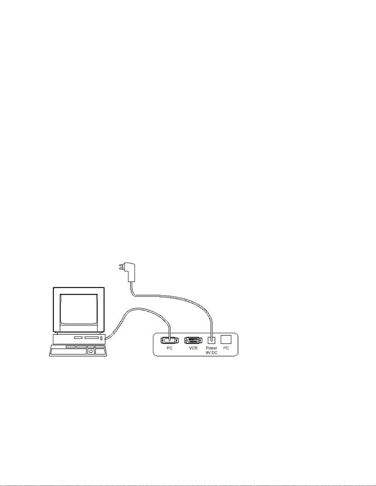
1. First, install the ComPair Browser software on your PC (read the installation
instructions carefully).
2. Connect the RS232 interface cable between a free serial (COM) port of your PC
and the PC connector (marked "PC") of the ComPair interface.
3. Connect the AC power adapter to the supply connector (marked "POWER 9V
DC") on the ComPair interface.
4. Switch the ComPair interface OFF.
5. Switch the Receiver box OFF (and remove the AC power).
6. Point the ComPair interface to the Service send LED (behind the cover) on the
front of the Receiver box.
7. Plug the AC power adapter in an AC power outlet and switch on the ComPair
interface. The green and red LEDs light up together. The red LED turns off after
approximately 1 second, while the green LED remains lit.
8. Start the ComPair program and read the "introduction" chapter.
Figure: ComPair set-up
Page 51

How to Order
ComPair order codes:
ComPair Software: ST4191
ComPair Interface Box: 4822 727 21631
AC Adapter: T405-ND
ComPair Quick Start Guide: ST4190
Error Codes
The error code buffer contains all detected errors since the last time the buffer was
erased. The buffer is written from left to right. When an error occurs that is not yet in the
error code buffer, it is written at the left side and all other errors shift one position to the
right.
How to Read the Error Buffer
It is possible to read out the error buffer in three ways:
• On the screen while in Service Alignment Mode (SAM). If there is a picture, this
is the easiest way to read the error buffer. In the SAM main menu, the last 10
error codes which have occurred are displayed. The most recently detected error
code is displayed on the left side. Examples:
§ 003 000 000 000 000: error code 3 is the last and only detected error.
§ 002 003 000 000 000: error code 3 was detected first and error code 2 is
the last detected (newest) error.
• With the "Code 1" and "Code 2" lines in CSM.
• With ComPair.
Page 52

How to Clear the Error Buffer
It is possible to clear the error buffer in two ways:
• By selecting the item "reset Error Buffer" in the SAM main menu.
• By pressing the following key sequence on the remote control transmitter:
• 0-6-2-5-9-9
Note: When the error buffer is full (10 codes), no new errors can be stored. The set
monitors how long every error is stored in the error buffer. If a false error is in the buffer,
it will be deleted after 50 hours. If an actual error is in the error buffer, it will be written to
the buffer again after 50 hours. This is a safeguard to ensure that the history of the error
codes is stored.
To help ensure that you are not reading false error codes, you may want to record the
contents of the error buffer, reset the buffer, and see which error codes are generated
again by the set.
Error Codes
If the set has non-intermittent faults, clear the error buffer before you begin the repair.
This to ensure that old error codes are no longer present.
If possible, check the entire contents of the error buffer. In some situations, an error
code is only the result of another error code and not the actual cause of the problem (for
example, a fault in the protection detection circuitry can lead to a protection).
Page 53
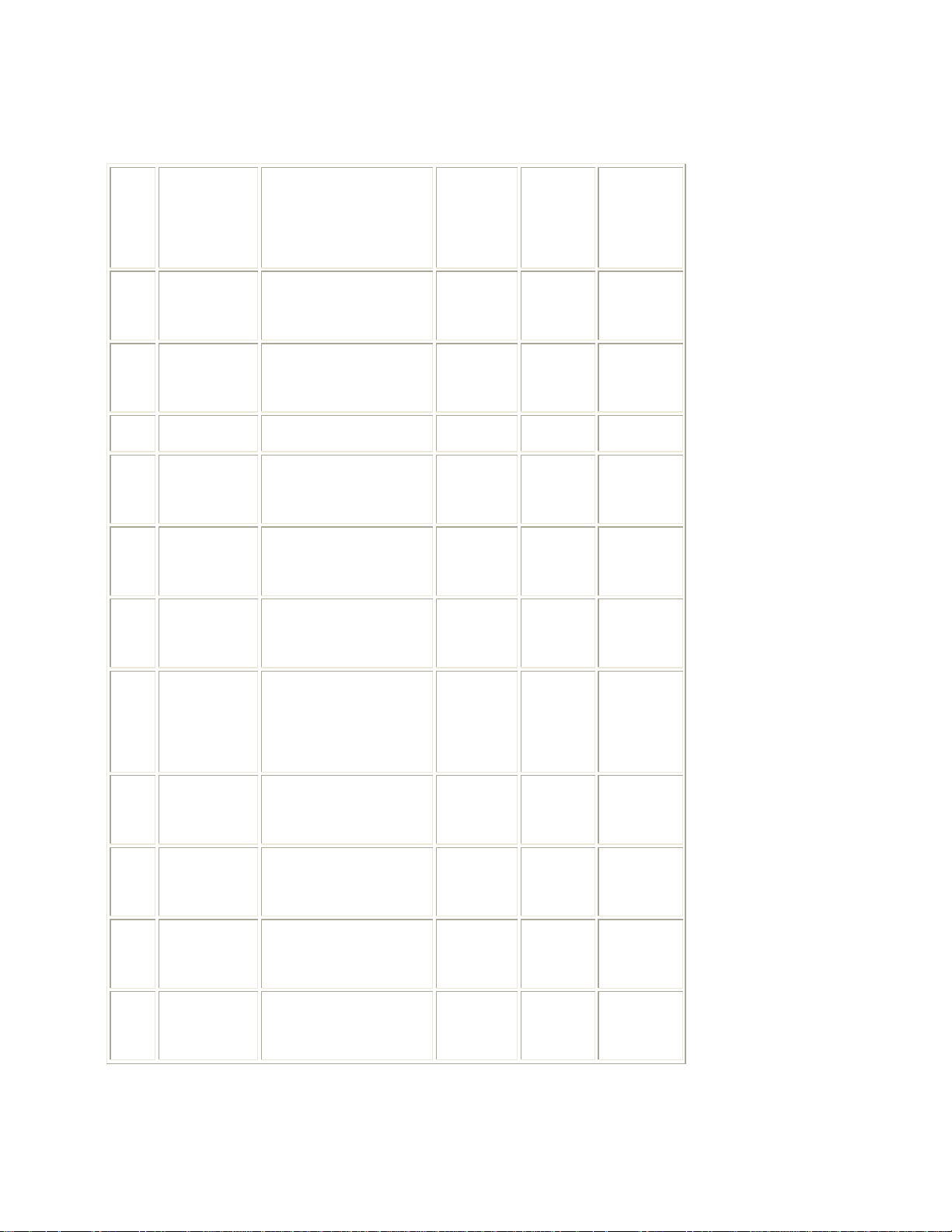
Table: Error Code Overview
Defective
Defective
Error Device Description
item
ST24E32
2
or M24C32
3 SAA5801
5 UV1316 Tuner U1102 K1 Tuner
10 TEA6415
11 TEA6422
15 TDA9320H
Non volatile
IC7008 K7 Control
memory
OTC2.5
IC7003 K7 Control
microprocessor/TXT
I/O source select
IC7208 K8
video
I/O source select
IC7777 K8
audio
HIP I/O-video
IC7501 K1
processing
Diagram
module
indication
Source
select
Source
select
Chroma
IF I/O
HOP video
20 TDA9330H
21 TDA9178 LTP Peaking IC7402 K6
MN8283 /
23
PD64083
25 MSP3410D
27 PCF8574 I/O Expander IC7880 AV8
control/deflection
processor
3D Comb IC - CB 3DComb
ITT sound
processor
IC7300 K6
IC7751 K3
Video
Controller
Video
Controller
Audio
module
AVinterface
Page 54
31
32
33
35
Video
30 TEA6415
TEA6422
FS402 Down Scaler IC7002 DS1 Down Scaler
ACEX-EPLD
UV1316 FDS Tuner U1102 M1
36 PCF8574
Selection
Switch
Audio
Selection
Switch
HD signal/sync
processing
FDS I/O
Expander
IC7710 AV7 AV-interface
IC7810 AV8 AV-interface
IC7360 AV3 AV Interface
Video Dual
Screen
Panel
Video Dual
IC7860 M2
Screen
Panel
37 SAB9079 FDS Popov IC7700 M4
38 TDA9320 FDS HIP2 IC7501 M1
39 M24C04 FDS NVM IC7991 M1
FDS
41 TDA7309
Headphone
IC7620 M5
Video Dual
Screen
Panel
Video Dual
Screen
Panel
Video Dual
Screen
Panel
Video Dual
Screen
Panel
Page 55
50 SAA4978H FBX Picnic IC7611 L1 Feature Box
Slow I 2 C bus
53 SAA4992 FBX Falconic IC7626 L3 Feature Box
Slow I 2 C
65
blocked
Fast I 2 C bus
66
blocked
67 Supply 5V 5V2 - +5V Supply 68 Supply 8V 8V6 - +8V Supply -
Tuner
80
protection
3DComb filter
81
protection
- -
- -
Tuner-PROT U1102 K1
3D-COMB
- 3D Comb
PROT
bus
blocked
Fast I 2 C
bus
blocked
-
-
+8V (Tuner)
Supply
3D Comb
Filter
Protections
The microprocessor (OTC) of the F21R Receiver box remains active during standby.
This because power of the microprocessor (and the attached memory chip set) is
coming from the 3V3 supply, which is derived from the 5V Standby circuitry.
Therefore, in both "Power on" as in "Standby" mode, the microprocessor is connected to
this power supply. The microprocessor controls the "Standby" line for switching "on" and
"off" the main supply. In the standby mode, or in the protection mode, the "Standby" line
will open the contacts of relay 1400 (diagram PS) via T7401, which results in switching
"off" the AC power input to the main supply.
Page 56

We can divide the F21R Receiver box protections in three groups:
1. Protection from I 2 C-busses (fast and slow) or I 2 C-IC errors (device errors).
2. Protection from the inputs on the OTC.
3. Protections from the status register of the HOP (communicated via I 2 C-bus).
Protection from the I2C bus
During normal operation, some registers of the I 2 C controlled ICs are refreshed every
200 milliseconds. During this sequence, the three I 2 C busses and the I 2 C ICs will also
be checked.
Possible protections:
• I2C bus protections. This will take place if the SDA and SCL are short-circuited to
ground or to each other.
• I2C device protections. This can occur when there is a malfunction in the
communication with one specific device, or if the power supply of the device is
missing.
• FBX and/or Tuner circuitry protection. If one of these circuits does not respond
for more than 1 second (measured via I 2 C), the Receiver box goes into
protection mode.
Protection from the inputs on the OTC
If a protection is detected at an input of the OTC, all protection inputs of the OTC will be
scanned every 200 milliseconds five times. If the protection on one of the inputs is still
activated after 1 second, then the set will go into protection mode.
Page 57

Possible protections:
• 8V6 and 5V2 protection. The presence of the 8V6 and 5V2 is sensed by the
OTC. If the 8V6 and/or 5V2 are/is not present, then an error code is stored in the
error buffer.
Protections from the status register of the HOP
Every 200 milliseconds the status register of the HOP is read by the OTC by I 2 C. If a
protection signal is detected on one of the inputs of the HOP, then the relevant error bit
in the HOP register is set to "high." If the error bit is still "high" after 1 second, the OTC
will store the error code in the error buffer, and depending on the relevancy of the error
bit, the set may or may not go into protection mode.
Possible protections:
• HFB protection. If the horizontal flyback is not present, then this is detected by
the HOP. One status bit is set to "high." The error code (71) is stored in the error
buffer, and the set will go into protection mode
Repair tips
How to Deal with a "TV configuration" Situation
It is not easy to access the CSM menu without the accompanying plasma monitor.
Therefore, it is best to retrieve this information while you still have the complete
configuration.
Depending on the fault, the problem may be easily solved. However, if this is not the
case, some of the data recorded could assist you in the repair.
Page 58

How to Deal with a "Receiver Box Only" Situation
Without the accompanying plasma monitor, the Receiver box will go into Standby mode
after a few seconds (this monitor detection is designed to prevent Philips Receiver
boxes from being used with other brands of monitors).
This detection can be overridden in the following way (to use, for example, a PC
monitor):
• Enter the SAM-mode via ComPair (using the "align" key of the DST simulation
mode), or through the HW intervention of connector 0356 on the SSP (pins 2 and
3). The set will now operate in SDM. Then short pins 1 and 2 to enter SAM.
• Via navigation in the SAM menu and selecting, you must follow this route:
"Service Options" - "Miscellaneous" - "Stand-alone."
• Toggle "No" to "Yes" and store this change (this means that a bit is changed in
the NVM).
• Now the Receiver box can operate with any monitor (for example, a PC monitor).
• The Service technician can now perform the diagnosis and repair (the CSM
menu can also be accessed now).
• When the problem is solved, the Stand-alone option bit should be reset to "No,"
to return the set to the original setting.
Miscellaneous Tips/Remarks
• Sometimes, when there is an NVM related error/problem and the set does not
want to start up, it can be helpful to start the set without the NVM (IC7008 on the
IC holder on the SSP). You can see OSD on the monitor, for a short time, so you
can conclude that much of the circuitry is working fine.
• If an empty EAROM (permanent memory) is detected, all settings are set to
preprogrammed default (standard) values.
• To overrule the childlock PIN code, use code "0711."
Page 59

• When the user settings related to optimal picture and sound performance are in
doubt, one can restore the default factory settings via: "Settings" - “General” "Reset AV settings," and pressing the "OK" key on the remote control transmitter.
This may help correct an incorrect user setting faster, since the starting point is
more clearly defined (for example, the set will leave the factory with "DNR" on
medium, "Dynamic Contrast" on medium, and "Sharpness" on 4, etc.).
Page 60

Electrical Alignments
Index of this chapter:
1. General Alignment Conditions
2. Hardware Alignments
3. Software Alignments
4. Option Settings
Notes:
• The Service Default Mode (SDM) and Service Alignment Mode (SAM) are
described in chapter 5. Menu navigation is done with the "cursor up, down, left
and right" keys of the remote control transmitter.
• Figures below can deviate slightly from the actual product, due to different set
designs.
General alignment conditions
Perform all electrical alignments under the following conditions:
• Power supply voltage: 110 V ± 10%, 60 Hz ± 5%.
• Allow the set to warm up for approximately 20 minutes.
• Voltages and waveforms are measured in relation to tuner earth (with exception
to the voltages on the primary side of the power supply). Caution: never use
heatsinks as ground.
• Test probe: Ri > 10 M ohm, Ci < 20 pF.
Page 61

While performing alignments, set the receiver box to the following settings:
• Dynamic contrast: OFF (via the "Picture" menu).
• Active control: OFF (via the remote control. The "Active Control" key is the key
between the smart keys, and toggles Active Control "ON" and "OFF").
• Smart Picture mode: Eco.
Hardware alignments
There are no hardware alignments necessary.
Software alignments
Notes:
• Alignments are stored automatically
• Dealer option settings are stored automatically
• Service option settings must be stored with the "store options" item in the top
level SAM menu. Turning the receiver box off and back on is not necessary to
store the values in NVM.
Put the set in SAM mode (see chapter 5). Now you can select the following alignments:
1. "General":
§ "Luma Gain"
§ "IF AFC"
§ "Tuner AGC"
§ "IF AFC Tuner 2"
§ "Tuner AGC Tuner 2"
§ "Blend intensity"
§ "FBX Test Pattern"
Page 62

2. "Drive":
§ "Test Pattern"
§ "Red"
§ "Green"
§ "Blue"
§ "Red BL offset"
§ "Green BL offset"
§ "Contrast"
3. "Lum. Del":
§ "Lum. Delay Pal BG"
§ "Lum. Delay Pal I"
§ "Lum. Delay Secam"
§ "Lum. Delay Bypass"
"General" alignments
"Luma Gain"
This item has a fixed value of 3.
"IF AFC"
Supply via a service generator (e.g. PM5518), or via off-air, a TV-signal, with a signalstrength of at least 1 mV and a frequency ending on "25", e.g. 61.25 MHz (channel 3).
Alignment procedure:
• During the "IF AFC"-parameter adjustment one can see OSD feedback on the
screen.
• The OSD feedback can give 4 kind of messages:
Page 63
Table: Table-AFC
AFC-window AFC-frequency versus reference
Out High
In High
In Low
Out Low
The first item ("In" or "Out") informs you whether you are in or out of the AFC window.
The second item ("High" or "Low") informs you whether the AFC frequency is too high or
too low.
1. Adjust the "IF AFC" parameter until the first value is within the AFC window (=
"In").
2. Next, adjust the "IF AFC" parameter until the second value is "Low."
3. After adjustment, "Store" the value.
"Tuner AGC"
Connect the RF output of a video pattern generator to the antenna input.
From the generator, input Supply an NTSC TV signal with a signal strength of
approximately 2 mV and a frequency of 61.25 MHz (Channel 3).
Measure the DC voltage on pin 1 of the Tuner (reference number 1102). You can adjust
this voltage by adjusting the "Tuner AGC" item in the SAM menu. Alignment is correct
when the DC voltage is just below 3.8 V.
Page 64

General remark for alignments related to the DW module (M):
The next two alignments are not stored in the main set NVM, but in the DW module
NVM (IC 7991).
The NVM protect line of this IC is not controlled by the main set microprocessor.
Therefore, before performing any DW module alignments, one needs to temporarily
bridge (with soldered wire) the test lead of pin 7 of the DW module NVM (IC 7991) with
the test lead 5 mm diagonally across (just under resistor 5502). This will disable the
protect line of the DW module NVM.
Important: Remove the wire bridge after storing the values.
"IF AFC Tuner 2"
Use the same procedure as described above (under "IF AFC") with the set switched to
the DW source.
"Tuner AGC Tuner 2"
Use the same procedure as described above (under "Tuner AGC") with the set switched
to the DW source.
"Blend intensity"
This adjustment aligns the level of transparency of the menu display that is blended into
the main display. Use this alignment when the main microprocessor or the HOP IC is
replaced.
1. Set the "Brightness," "Contrast," and "Color" values (in the "Picture" menu) at the
midpoint.
2. Using a video pattern generator, apply a signal with a 100% white video pattern
to the set.
Page 65

3. Connect an oscilloscope to the Red output of the Receiver box (sub-D connector
AV303) and measure the Red output level.
4. Align the "blend intensity" parameter so that the blended signal is 65 % of the
black/white amplitude. This ratio will be about 0.45 V (blended signal) to 0.7 V
(full white signal).
5. This parameter can be adjusted from 0 to 31.
"FBX Test Pattern"
When this pattern is switched on, the set will display a picture that slowly changes from
black to white, and vice versa. Use this pattern to check the functionality of the circuitry
behind the FBX and the FBX function itself.
You can also use this pattern as a picture generator for the Flat TV plasma monitor (for
example, for checking cell defects, interpretation of the ADC/DAC converters, etc.).
Important: Be sure to set this pattern to "OFF" again when it is no longer needed, since
it will not be automatically disabled when SAM is exited.
"Drive" alignments
"Test Pattern"
The test pattern is not really needed for the alignment of the Receiver box. It can be
used in the TV configuration as a test pattern to align the white color temperatures of
the monitor. However, the monitor itself (as a stand alone unit) can also be aligned in
other ways (described in the Service Manual of the monitor).
Page 66

RGB Output Amplitude Adjustment
1. Load the RGB output (sub-D connector AV303) of the Receiver box with a
monitor (or match RGB output lines with 75 ohm resistors, if no monitor is
available), and measure the outputs with an oscilloscope.
2. Apply an artificial white CVBS signal (1Vpp white-to-top-sync, with a 0.3V sync
amplitude) to the external 2 input.
3. Set Luma Gain to a value of "3" (via the SAM menu "Alignments" - "General").
4. Set "Red," "Green," and "Blue" to "24" (via the SAM menu "Alignments" -
"Drive").
5. Set "Red BL offset" and "Green BL offset" to "7."
6. Adjust the gain (with the "Red," "Green," and "Blue" slider bars) until the
oscilloscope-measured values for R, G, and B are 700 mV ± 10 mV.
"Lum. Delay" alignments
With this alignment, you place the luminance information directly on the chrominance
information (brightness is pushed onto the color). Input a color bar or gray scale pattern
as a test signal.
"Lum. Delay PAL BG"
Set the value to 7. If the luminance signal referred to the chrominance signal still has a
time delay, adjust the value to solve this.
Page 67

"Lum. Delay PAL I"
Set the value to 8. If the luminance signal referred to the chrominance signal still has a
time delay, adjust the value to solve this.
"Lum. Delay SECAM"
Set the value to 11. If the luminance signal referred to the chrominance signal still has a
time delay, adjust the value to solve this.
"Lum. Delay Bypass"
Set the value to 10. If the luminance signal referred to the chrominance signal still has a
time delay, adjust the value to solve this.
Option settings
Introduction
The microprocessor communicates with a large number of I 2 C ICs in the set. To
ensure good communication and make digital diagnosis possible, the microprocessor
has to know which ICs to address. The presence or absence of specific ICs or functions
is made known by means of the option codes.
All options codes can be manipulated using both the Option Numbers and/or the Option
menu.
All hardware related options are incorporated under the heading "Service Options" on
the SAM main menu.
All software related options are incorporated under the heading "Dealer Options" on the
SAM main menu.
Page 68
Dealer Options
Table: Table Dealer Options
Menu
Subjects Options Physically in set
name
Yes
Picture
Black mute active when there is
no signal detected
Personal
Options
Mute
Virgin
Mode
No
Yes
No
Noise when there is no signal
detected
TV starts up once with language
selection menu when turned on
for the first time (virgin mode)
TV does not start up once with
language selection menu when
turned on for the first time (virgin
mode)
Page 69
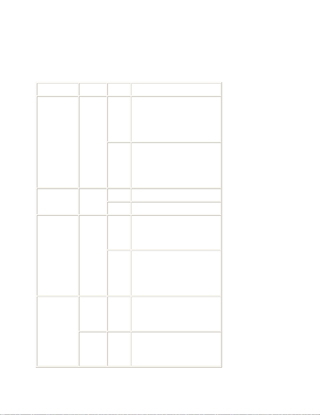
Service Options
Standby when connected to PC
Table: Table Service Options
Menu-item Subjects Options Description
Receiver-box can operate with
42" F19D-monitor, when
F19
jumper settings on AVI-panel
are configured in 1.9-mode.
Monitor type Monitor
Receiver-box can operate with
32" FM23-monitor, when
FM23
jumper settings on AVI-panel
are configured in 2.3-mode.
Video repro
Miscellaneous
Opt. No.
Light
sensor
Stand
Alone
Group 1
Yes This possibility does not exist.
No Fixed.
Option needed for Service to
Yes
No
be able to service the receiverbox with a normal PC monitor.
Default setting. In this setting,
the receiver-box will go to
monitor.
e.g. 04492 08449 49555 04112
(see sticker on bottom receiverbox).
e.g. 04151 00000 00000 00257
Group 2
(see sticker on bottom receiverbox).
Page 70

Option numbers
If the EAROM is replaced, all the options will require resetting. To be certain that the
factory settings are reproduced exactly, both service option numbers must be reset.
These numbers can be found on the bottom of the Receiver box.
Page 71

Circuit Descriptions, List of Abbreviations, and IC Data Sheets
Index of this chapter:
1. Introduction
2. Power Supply Unit (PS)
3. Audio Video Interface panel (AV)
4. Down Scaler panel (DS)
5. Small Signal Panel (K)
6. Double Window panel (M)
7. Front panel (FP)
8. High Definition panel (HD)
9. Abbreviations
10. IC Data sheets
Page 72
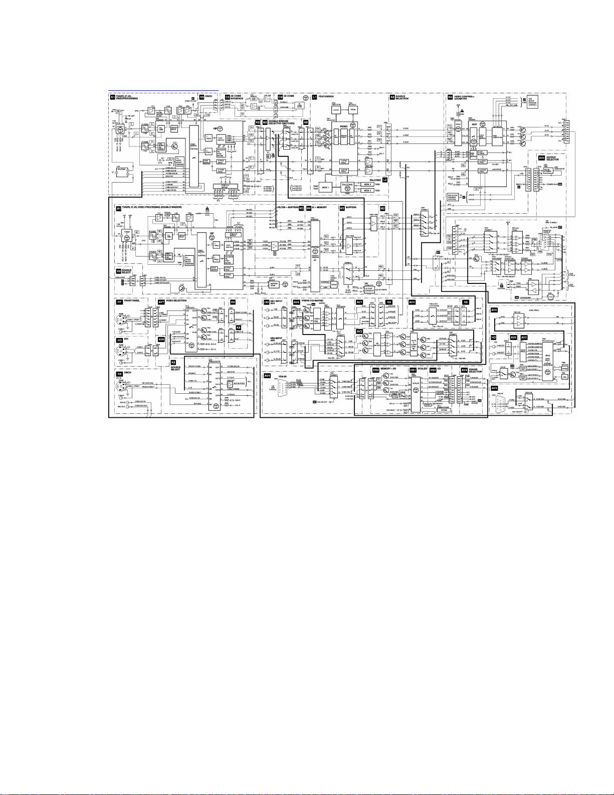
Block diagram Video
Page 73
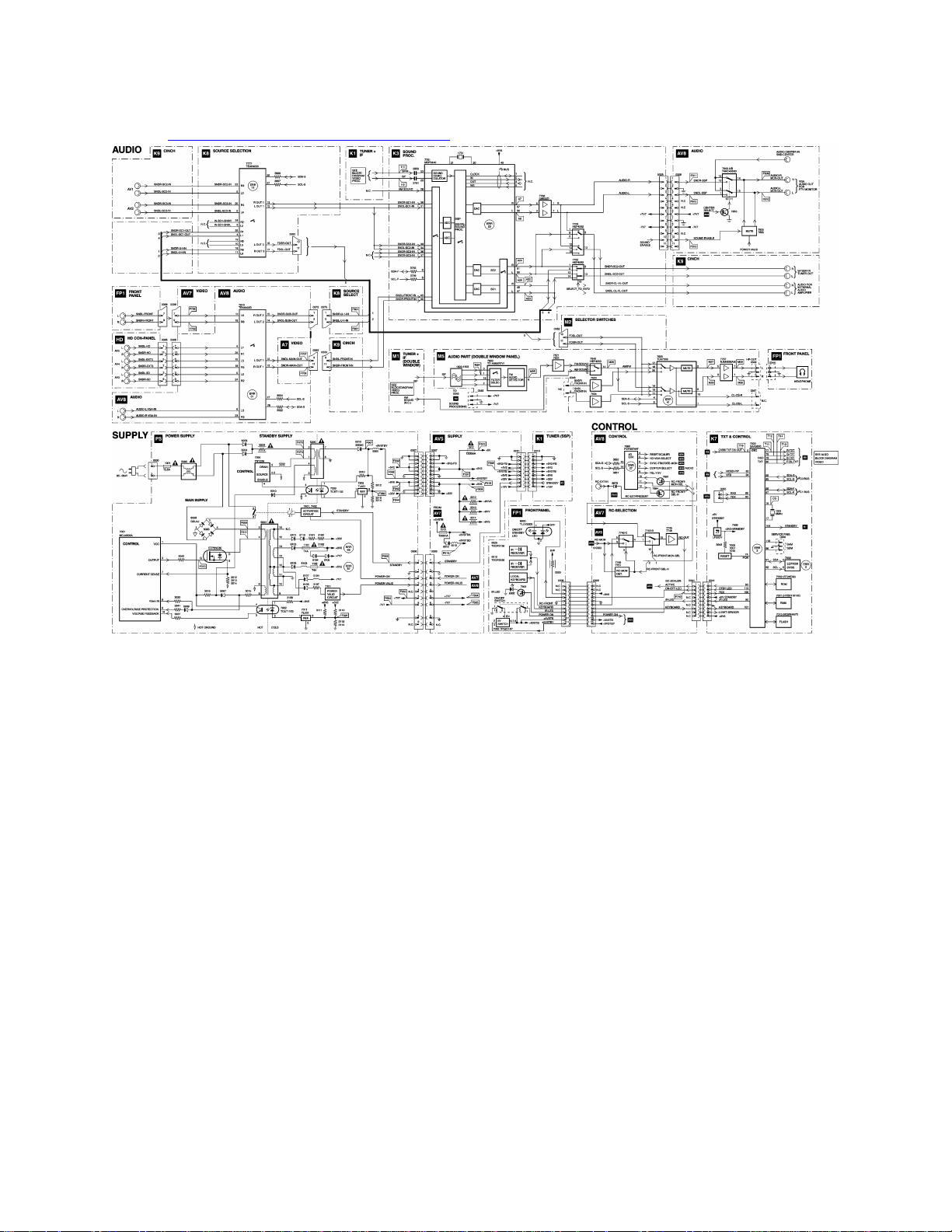
Block diagram (Audio and Supply)
Note:
• Figures can deviate slightly from the actual product, due to different set designs.
• For a good understanding of the following circuit descriptions, please use the
diagrams in chapter 6 and 7. Where necessary, you will find a separate drawing
for clarification.
Page 74

Introduction
The F21R is developed for the global market. The service chassis name of this
Receiver box is F21RU.
It is a newly designed Receiver box, and is based on the SSP architecture of the MG98
chassis. It can drive both the FTV1.9 and FM23 plasma screens.
The F21R is built around the MG SSP and some additional panels:
• The SSP is based on the MG98 (very similar to the MG3.1U SSP) instead of the
previous "old" GFL chassis + "MG" circuits (DW module and FBX).
• New Power Supply.
• New AV Interface Panel (with jumper changes and other option settings ("config-
ident" or "FSP") in order to work together respectively with an FTV1.9 or an
FM23 plasma monitor.
• New Down Scaler panel.
• New Front I/O panel.
• New High Definition connector panel.
Page 75
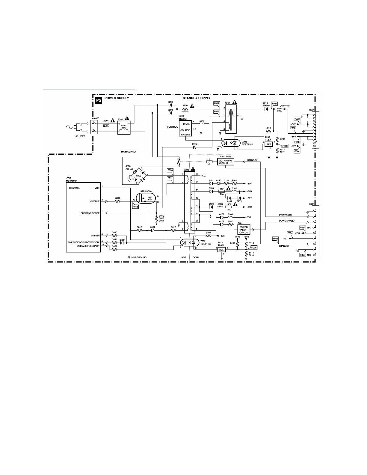
Power Supply Unit (PS)
Block diagram Power Supply
Introduction
A new 35 W power supply is developed for the Receiver box. It delivers the voltages for
the SSP, the DW, the FBX (+5VSTB, 5V2, 8V6, 7V7, -7V7 and 33V) and for the specific
CBAs.
The output of the power supply is connected to the AVI panel. All the other CBAs are
powered by this panel.
The AC Power is applied to the input filter that feeds it to the standby supply. This
supply is always operational and delivers the +5VSTBY voltage.
Page 76

The task of the main supply is to deliver the supply voltages for the several electrical
circuits in the Receiver box. It is switched via a single-pole relay, which is powered from
the +5VSTBY voltage and controlled via the POWER_ON and STANDBY signals.
The reason to choose for a separate standby supply, instead of a single flyback supply
(which can be driven in standby mode like a MC44604), is the requirement to have a
very low standby power consumption.
The "POWER ON/STBY" knob is located on the Front I/O panel and is connected to the
keyboard control function of the OTC. Switching from standby to on is under control of
the OTC.
With this (mechanical) switch, the relay supply is disabled. The second contact in the
switch is used to send the "on/off" ("POWER_VALID") info to the OTC.
The green "POWER ON" LED is active, when the 8.6 V is present (HW controlled).
The red "STANDBY" LED is active in standby. This is under control of the OTC
("ON_OFF_LED").
The Power Supply module consists of three parts:
1. AC Power inlet and filter.
2. Standby supply.
3. Main supply.
AC Power Inlet and Filter
The AC Power is provided by inlet 0300, after which it is fused by a T2.5A fuse. The
next part, the AC Power filter, consists of a LC-common mode filter section. This filter
consists of two capacitors (items 2002 and 2004) from both phase and neutral to ground
(to reduce the leakage current) and an inductor (5000). Interferences on one of the
phases are shorted to ground by these capacitors.
Page 77

Inductor 5000 also provides a differential-mode filtering with capacitor 2001. Resistor
3003 discharges this capacitor after the AC Power is disconnected.
At high voltage peaks (for example, lightning surges) on one of the phases, the
resistance of VDR 3002 will be very low, causing fuse 1001 to interrupt. At a lightning
surge on both phases with respect to chassis ground, AC Power filter 5000 will form a
high resistance, through which the voltage will rise very sharply. To prevent flashovers,
a spark gap (item 1000) is implemented.
Resistors 3000 and 3001 are connected between neutral and chassis ground. They are
required by safety regulations.
Standby supply
Start up
The standby supply operates on the AC voltage from the input filter part, and has to
deliver a stable regulated 5 V voltage. The standby supply is always operational when
the AC input voltage is present, even when the POWER switch is in the "off" position.
After a small bridge rectifier and buffer capacitor (D6203/6204 and C2202), the DC
voltage is applied to a switched mode power supply. To reduce self pollution, the
rectifiers are bridged by small capacitors (C2200/2201).
Normal Operation
The standby supply itself is build around a "TINYSwitch" TNY256. This IC contains the
control circuitry needed for an SMPS and a power MOSFET. It uses a simple on/off
control loop to regulate the output voltage.
The supply for the TNY256 comes via safety resistor R3200, L5200, and L5202.
Page 78

The +5VSTBY voltage at the secondary side is rectified by D6310 and smoothed by
C2311.
By using secondary sensing, a very accurate +5VSTBY voltage and high efficiency is
achieved. The sensing circuit uses a TL431 as reference voltage/error amplifier.
Optocoupler 7203 and coil 5200 are used for the AC Power isolation.
When the +5VSTBY output voltage rises, the reference voltage on the TL431 will
exceed 2.5 V and the current through this device and the optocoupler LED will increase.
By this method, the optocoupler transistor will conduct more. When this current (at pin 4
of IC7200) exceeds 50 uA, the MOSFET is switched "off," and the output voltage will
drop. When this current drops below 40 uA, the MOSFET is switched "on" again.
Output Voltage
• +5VSTBY (available on connector 0307, pin 7).
Protections
As the TNY256 is sensitive for transients, a "peak clamp" circuit (300 V zener diodes
6201 and 6202) is used to limit the voltage to a safe level.
Main supply
Introduction
The main supply is activated by single-pole relay 1400, which delivers the filtered AC
Power to a rectifier bridge (item 6000). This rectified voltage is the input for the flyback
converter, which generates the output voltages.
The flyback converter is based on a MC44603AP driven in "discontinues conduction
mode" with a fixed frequency of 40 kHz (at nominal AC Power voltages). The
MC44603AP drives a MOSFET (600 V, 1.2 Ohm), which is snubbed (by 2008) and
Page 79
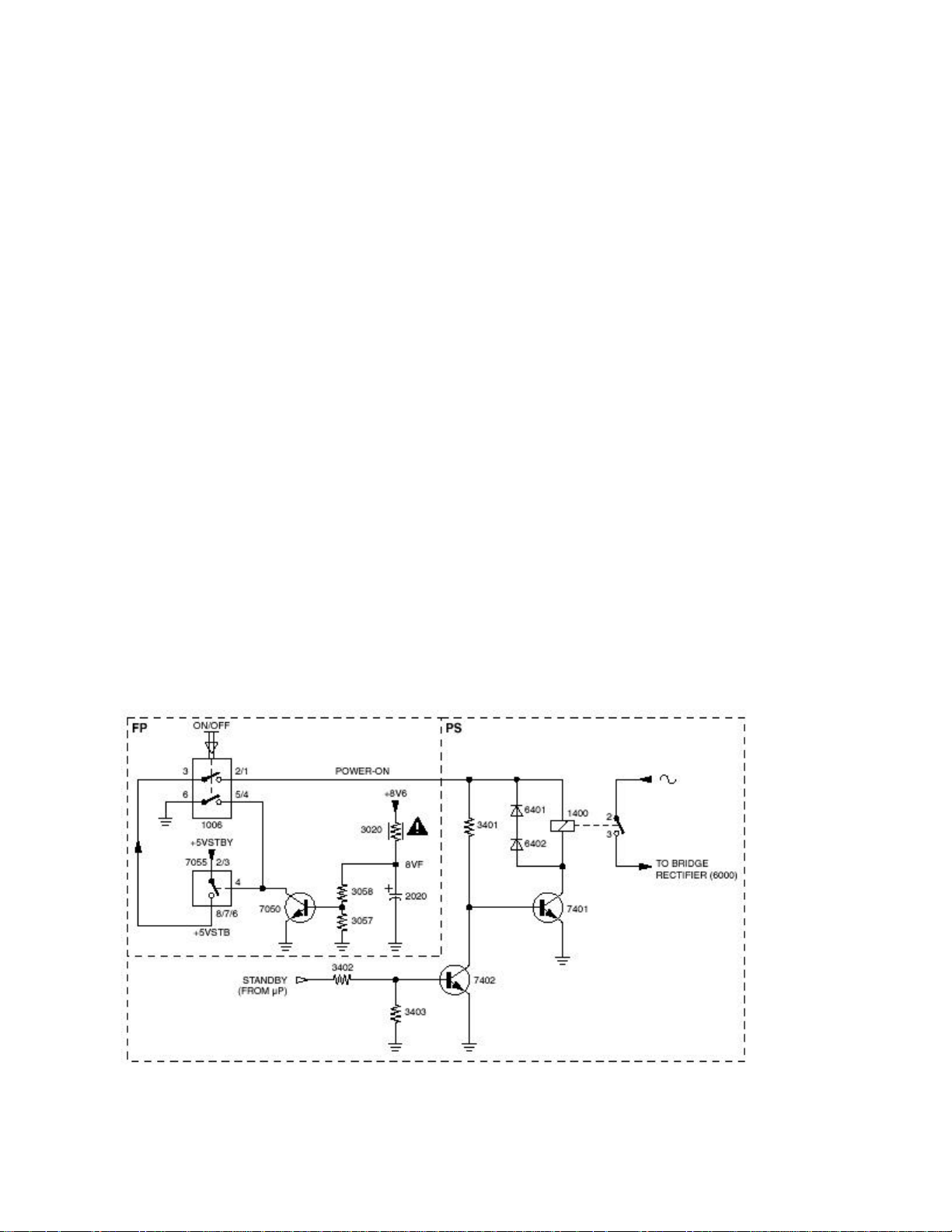
clamped by an RCD peak clamp. The transformer delivers the secondary output
voltages and the primary supply voltage for the IC.
Secondary voltage control is on the 5V2 and 8V6 output via a TL431 (item 7011) and an
optocoupler (item 7002) back to the error amplifier input of the controller IC.
Output Voltages
The following voltages are generated by the main supply:
• +33V (0307/11) for the Tuner.
• +16V (0306/9)
• +8V6 (0307/8 & 9)
• +7V7 (0306/5)
• -7V7 (0306/6)
• +5V2 (0307/4 & 5)
• +5V2_FB (0307/3)
Start up
Figure: Start up circuitry
Page 80

The "on/off" switch (item 1006/1007) on the Front I/O panel drives IC7055. This is a
"power distribution switch," used due to the high switch-on current. It has internal
overload and short-circuit protections.
A single pole 5 V relay (item 1400) is used to switch the Receiver box from "standby" to
the "on" state. It is controlled via the "POWER_ON" line.
The start up supply voltage of the control IC comes via the standby supply. It is rectified
(D6010), smoothed (C2025), and clamped (D6008). Once the main supply is started,
this voltage is taken over by winding 6-8 of transformer 5003 and diode D6007.
Normal operation
The working frequency of 40 kHz is determined by R3032 and C2014. The output
voltage is controlled by duty cycle regulation. Output is on pin 3, which drives the FET.
A current will flow through transformer coil 3-4 (item 5003), FET 7000, and senseresistors R3012//R3013//R3014 to ground. The energy stored in the primary winding
during the on time is delivered to the secondary windings during the "off" time.
The output voltages are rectified and buffered here.
Regulation is performed by the control loop that consists of reference component 7011
and optocoupler 7002. When the +5V2 output voltage rises, the reference voltage on
the TL431 will exceed 2.5 V and the current through this device and the optocoupler
LED will increase. By this method, the optocoupler transistor will conduct more, and the
voltage over R3035 (and pin 14 of IC7001) will rise. The IC will adjust the duty cycle, the
FET will conduct less, and the output voltage will decrease.
Page 81

Protections
Soft Start and Maximum Duty Cycle
The output voltage is 0 V at start up. This would force IC 7001 to start with a maximum
duty cycle, causing a very high current through FET 7000. To prevent this, capacitor
C2018 (at pin 11 of IC7001) ensures a soft start (voltage at pin 11 is low at start up,
which gives a small duty cycle) and R3039 determines the maximum duty cycle.
Switch Off Peak Voltage
To protect the FET against high peak (drain-source) voltages at switch "off," a peak
clamp circuit is added consisting of D6014, D6002, C2007, and R3010.
When the FET blocks, the diodes will lead the peak voltages away from the FET and
will charge C2007.
When the FET conducts, this capacitor is discharged via R3010, the primary coil, and
the FET itself.
Over Current and Fold Back
The current through the primary winding is measured by sense resistors R3012, R3013,
and R3014. The resulting voltage is measured at pin 7 of IC7001. Once the voltage at
this pin exceeds 1 V (so maximum current is set to 3 A), the duty cycle is regulated
back.
If the output load keeps on increasing (I > 3 A), the system is unable to supply enough
energy to maintain the output voltage in regulation. This is detected at pin 5 of IC7001
(via pin 8 of 5003, R3015, D6007 and R3037). Consequently, if this voltage drops below
the fold back threshold voltage of 1 V, the IC will adapt the "current sense threshold."
This will limit the current supply and by this, the output voltage. This will cause an
avalanche effect, causing the supply to rapidly trim down.
Page 82

Over Voltage
When the voltage on pin 6 of IC7001 will exceed 2.5 V, the control IC will stop
oscillating (after 2 us). The output voltages will drop, and the IC starts again. This can
happen when the feedback loop is interrupted.
Demagnetization
The internal demagnetization block in IC7001 disables the output (pin 3) during the
demagnetization phase of transformer 5003. This is to prevent the FET from being
switched "on." The info is taken from pin 8 of transformer 5003, and fed via R3015 and
R3030 to pin 8 of IC7001. When the voltage on this pin drops below 65 mV, the
demagnetization phase is completed, and the FET can switch on.
Audio Plop
The "POWER_VALID" circuit is designed to detect the disappearance of the AC Power
(at set switch "off" or at AC Power dips). This signal will then mute the audio outputs to
prevent audio plops (see diagram AV8 position I7).
The circuit compares the +5V2 output with the negative rectified 5V2 winding (which is
in fact the transformed rectified AC Power). When this voltage disappears, transistor
7101 is activated and the "POWER_VALID" output will go "low" before the supply output
voltages will drop. It will mute the audio outputs and stay "low" until the AC Power and
the +5V2 output voltage returns.
Page 83
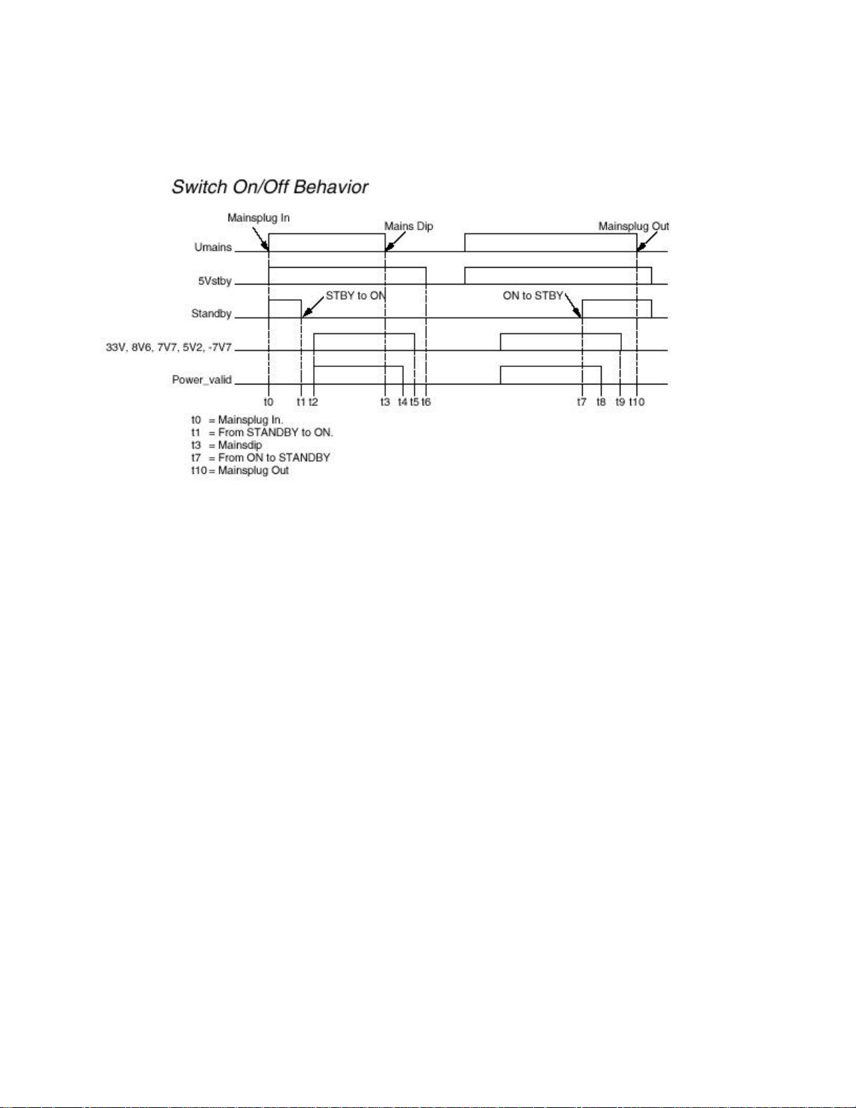
Switch On/Off Behavior
Figure: Timing diagram Power Supply
The start up of the PSU has to fulfill certain requirements.
At the moment the AC Power cord is connected (t0), the standby supply will generate
the "+5VSTBY."
(coming from the "STANDBY" pre-condition). With this voltage present, the
microprocessor begins the start up procedure, by making the "STANDBY" command
logic "low" (t1) and the "POWER_ON" command "high."
(coming from the "OFF" pre-condition). After you press the power switch on the front
panel, the "POWER_ON" signal will become "high" and within 2 seconds the main
supply will start, making the "POWER_VALID" signal "high" (t2).
When an AC Power dip occurs (t3), the "POWER_VALID" signal must go "low" before
the output voltages will drop and must remain "low" until the AC Power returns.
When you put the set in standby, the microprocessor makes the "STANDBY" signal
"high" (t7). The output voltages will drop, and the "POWER_VALID" signal goes "low,"
but the "+5VSTDBY" remains present.
Finally, this voltage will drop when the AC Power cord is disconnected (t10).
Page 84

Typical timing values are:
• t1 - t2 = 0.1 < t < 1.2 s (dependent on the "STANDBY PSU" load).
• t3 - t4 = 20 < t < 350 ms (dependent on U_MAINS).
• t5 - t6 = 10 < t < 1000 ms (dependent on U_MAINS and the "STANDBY PSU"
load).
• t7 - t8 = 10 < t < 600 ms (dependent on U_MAINS and the "MAIN PSU" load).
• t8 - t9 = 5 < t < 40 ms (dependent on the "MAIN PSU" load).
Page 85
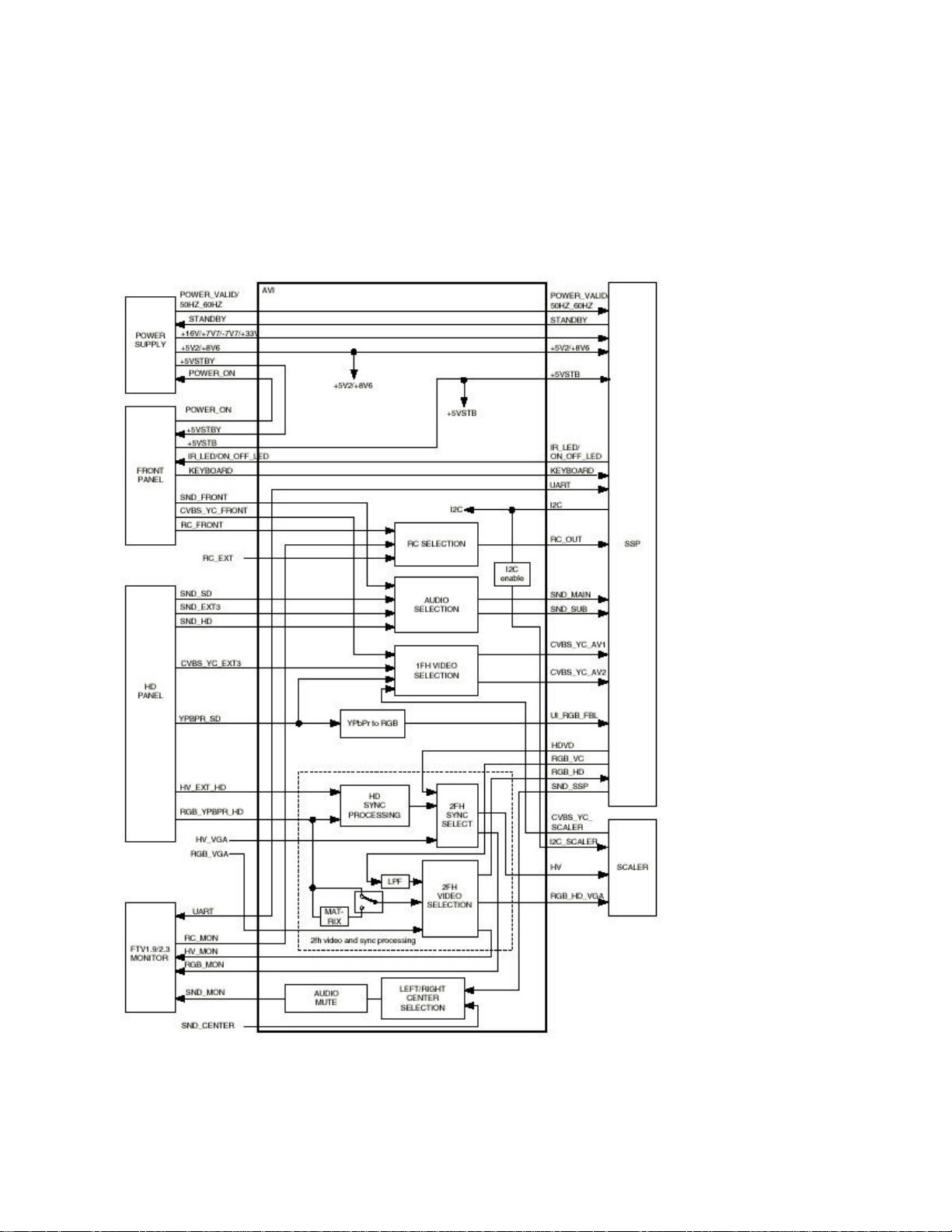
Audio Video Interface Panel (AVI)
Introduction
Figure: Block diagram AVI panel
Page 86

The AVI panel is an interface between the following panels/sources:
• Small Signal panel (SSP).
• Down Scaler panel (DS).
• Front panel (FP).
• VGA input.
• High Definition panel (HD) with:
§ YpbPr_HD or RGB_HD + external HV or external CSYNC.
§ YpbPr_SD input.
§ Extra YC/CVBS input.
• Power Supply panel (PS).
It also contains the output to the plasma monitor.
The AV Interface contains the following functions:
• YPbPr 480i/576i to RGB matrix (PAL/NTSC matrix).
• Combined YPbPr 480p/576p to RGB matrix (PAL/NTSC matrix) and YPbPr
720p/960p/1080i/1080p to RGB matrix (ATSC matrix).
• Sync separator for YPbPr 480p/576p/1080i.
• Sync format detection.
• Set H_HD and V_HD sync to SSP for frequencies that are not supported by the
MG98 SSP.
• Source selection for 2fH video signals:
§ RGB from HD input or from YPbPr to RGB matrix output (RGB_HD).
§ RGB from RGB_HD input.
§ RGB coming from HOP video controller on SSP (RGB_VC).
§ RGB coming from VGA input (RGB_VGA).
• Source selection for 2fH sync signals:
§ Sync signals belonging to YPbPr_HD.
§ Sync signals belonging to RGB_HD.
Page 87

§ Sync signals coming from FBX on SSP (HD/VD)
§ Sync signals from VGA input (HV_VGA)
• Source selection for CVBS and YC video signals coming from:
§ Front panel (CVBS_YC_FRONT).
§ Extra external CVBS/YC input (CVBS_YC_EXT3).
§ Scaler (CVBS_YC_SCALER).
• Source selection for audio signals belonging to:
§ YPbPr_HD or RGB_HD (SND_HD).
§ YPbPr_SD (SND_SD).
§ CVBS or YC EXT3 (SND_EXT3).
§ RGBHV VGA (SND_VGA).
§ Center audio input.
• Source selection for RC signals coming from:
§ Monitor (RC_MON).
§ E-box (RC_FRONT).
§ External (RC_EXT).
• Output buffer for RGBHV signals going to the monitor.
• HFB generator.
• Feed through for (no processing of these signals on the AVI):
§ Supply voltages.
§ Control signals from/to Front panel to/from SSP.
§ UART signals from/to OTC.
2
• I
C enable/disable to scaler
The AVI contains a video switch, an audio switch, an I/O expander, and an EPLD (or
ACEX) with IC control. Two control signals used on the AVI come from the main uP of
the SSP. These control signals are:
• SOUND_ENABLE.
2
• I
C_SCALER_ACTIVE.
Page 88
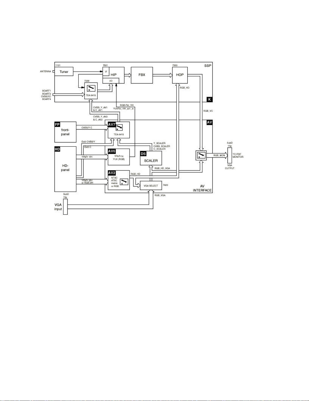
Video Processing
Figure: Block Diagram Video Processing
1fH CVBS and YC Video Processing (diagram AV6)
The source selection of CVBS and YC is done with a TEA6415 video source selection
IC. There are five input signals and two output signals.
Inputs are:
• CVBS or Y/C from FRONT.
• CVBS or Y/C from EXT3.
• Y/C from Scaler.
• CVBS from Scaler.
• Y from SD input used for sync for SD.
Page 89

Outputs are:
• CVBS_Y_AV1 and C_AV1.
• CVBS_Y_AV2 and C_AV2.
AV1 is connected to the CVBS/YC_FRONT input of the SSP (connector 0333).
AV2 is connected to the CVBS/YC_UI input of the SSP (connector 0372).
The YPbPr signals are buffered and fed through a YPbPr to RGB matrix circuit (TSH93,
item 7607). The matrix is made with discrete hardware and determined by resistor
values.
The RGB_SD output signals are then fed to connector 0372 and routed, via an RGB
selector, to the RGB2 (Universal Interface) input of the HIP IC (item 7501) on the SSP.
SD, HD, and VGA Video Selection (diagram AV7)
For HD sets the YPBPB_SD input can handle both 1fH (=SD) and 2fH (=HD) YPbPr
signals. The 1fH/2fH detection is done by the EPLD or ACEX (see "sync processing"
below).
If the YPBPR_SD input signal is 1fH, the YPbPr signal is converted to RGB with an
NTSC matrix and connected by switch S1 (TEA6415 on AV7) to the SSP via connector
0372.
If the YPBPR_SD input signal is 2fH, switch S1 is put into tri-state with the 1FH control
signal automatically (no software needed).
The sets also have a second HD input. This input is called RGB_YPBPR_HD and can
handle both 2fH RGB+HV and 2fH YPbPr signals.
The selection between 2fH YPbPr signals coming from the YPBPR_SD input and
RGB_YPBPR_HD input is done with switch S2 (on AV2). This switch is controlled with
the HD2_SEL control signal (software control). The output of S2 is called YPBPR_HD.
Page 90

The YPBPR_HD signal is converted to 2fH RGB with a switchable ATSC-NTSC matrix.
The switching between ATSC and NTSC matrix is done automatically by the
MATRIX_SEL control signal. This signal is generated by the ACEX automatically (no
software needed).
The output of the matrix is connected to a so-called “sync remover” circuit. This circuit
removes the sync pulses from the RGB signal in order to prevent clamp errors. The
CLAMPN (=clamp not) and BLANK signals needed for the sync remover are created by
the ACEX.
If the selected source is RGB_YPBPR_HD (HD2_SEL =1) AND the input signal on this
source is RGB+HV, the EXT_SYNC_PRESENT control signal becomes high. Now the
ATSC-NTSC matrix is bypassed with switch S3 automatically (no software needed).
The output of S3 is connected to the SSP via switch S4. In order to prevent clamp
problems in the double window module, switch S4 is put into tri-state in case the
selected source for the main picture or sub picture is not HD. This is done with the
FBL_HD control signal.
Page 91
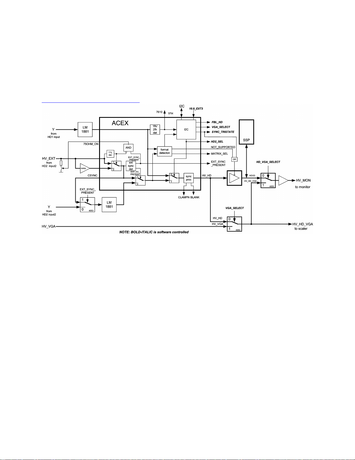
Sync Processing
General
Block diagram Sync Processing
The block diagram above shows the HD and VGA sync path. The AV Interface has the
following sync inputs:
• Sync from VGA source (H/V_VGA)
• Sync from HD source (H/V_HD)
• Sync from SSP (H/V_D)
The first HD input can handle both 1fH YPbPr and 2fH YPbPr and is called YPBPR_SD.
If the input signal is 1fH, the 1FH control signal becomes high automatically and the
signal is connected to the SSP. In this case the sync processing is done on the SSP.
The 1FH signal is generated by the ACEX.
The second HD input is called RGB_YPBPR_HD. This input can handle the following
signals:
Page 92

Note: The H-SYNC and CSYNC inputs share the same input connector. The TTL- and
the 75 Ohm inputs also share the same input connector. Switching "on/off" of the 75(
input resistor is done automatically via the 75OHM_ON signal generated by the ACEX.
The key components for HD sync processing are:
• A first LM1881 used for sync separation for "sync on Y" of the YPBPR_SD input.
The outputs are LM_CSYNC1 and LM_VSYNC1.
• A second LM1881 used for sync separation for "sync on Y" and CSYNC of the
RGB_YPBPR_HD input. The outputs are LM_CSYNC2 and LM_VSYNC2.
• An LM319 comparator used as a sync slicer for 0.3Vpp/75 Ohm sync inputs
(H/CSYNC+V). The outputs are V_SYNC_COMP and H_CSYNC_COMP.
• An ACEX used for:
§ 1fH/2fH detection for YPBPR_SD input.
§ External HV or CSYNC sync present detection for RGB_YPBPR_HD
input.
§ TTL / 0.3V detection for external HV or CSYNC for the RGB_YPBPR_HD
input.
§ Switch on/off 75 Ohm at the HV input.
§ System detection (480p/576p/1080i/720p).
§ Detection of not supported signals.
§ Converting CSYNC coming from LM1881 to H_SYNC.
The selection between VGA and HD is done with the VGA_SELECT control signal.
The selection between HD1 (YPBPR_SD) and HD2 (RGB_YPBPR_HD) is done with the
HD2_SEL control signal.
If a 2fH HD source is selected, the sync coming from the SSP has to be put into tristate. For all other sources, the sync coming from HD has to be put into tri-state.
If the selected HD signal is not supported by FTV2.1 (fH > 35 kHz), the
NOT_SUPPORTED control signal becomes “1” and the HD sync is put input tri-state.
Page 93

HD1 input (YPBPR_SD)
The Y signal coming from the HD1 input (YPBPR_SD) is fed to an LM1881 sync
separator. The LM1881 has two outputs, a composite sync output (LM_CSYNC1) and
vertical sync output (LM_V SYNC1). In the ACEX the composite sync output is
converted to a H sync signal (H_HD1).
The vertical output of the LM1881 is a negative going sync pulse. Depending on the
standard, this can be a double pulse. In the ACEX this pulse is converted to a single
positive going vertical pulse (V_HD1).
The H_HD1 and V_HD1 signals are fed to a format detection circuit. With this circuit, the
format of the input signal is detected and stored into an I 2 C register. Furthermore the
format detection circuit has three control outputs:
• 1FH (=”1” if the input signal is 1fH).
• MATRIX_SEL1 (=”1” if the input signal is 480p or 576p).
• NOT_SUPORTED1 (=”1” if the input signal is not supported by FTV2.1).
HD2 input (RGB_YPBPR_HD)
The Y signal coming from the HD2 input (RGB_YPBPR_HD) is fed to an LM1881 sync
separator. This LM1881 has two outputs, LM_CSYNC2 and LM_V SYNC2. In the
ACEX, the LM_CSYNC2 output is converted to a H signal (H_HD2).
The vertical output of the LM1881 is a negative going sync pulse. Depending on the
standard, this can be a double pulse. In the ACEX this pulse is converted to a single
positive going vertical pulse (V_HD2).
The H_HD2 and V_HD2 signals are fed to a format detection circuit. With this circuit, the
format of the input signal is detected and stored into an I 2 C register. Furthermore the
format detection circuit has two control outputs:
Page 94

• MATRIX_SEL2 (=”1” if the input signal is 480p or 576p)
• NOT_SUPORTED2 (=”1” if the input signal is not supported by FTV2.1)
The ACEX has two HV inputs for external HD2 sync signals, one for TTL and one for
0.3Vpp/75 Ohm (via comparator LM319).
Format Detection
The ACEX is also taking care of the HD standard detection. The detection is done by
counting the number of lines between two vertical pulses. The following standards can
be detected:
• 480i/576i (fH = 15.75 kHz/15.625 kHz).
• 480p (fH = 31.5 kHz).
• 576p (fH = 31.25 kHz).
• 1080i (fH = 33.75 kHz).
• 720p (fH = 45.0 kHz).
• other (H + V sync pulses are detected, but the format is not according the
standards mentioned above).
If any valid sync signal is detected, the SYNC_VALID control signal is set to “1." The
SSP of the F21RU can only handle standards with a line frequency < 35 kHz (480p,
576p and 1080i). If the detected sync is not 480p, 576p, or 1080i, the
NOT_SUPPORTED_DETECTED control signal is set to “1."
The format detection is done for both the HD1 (YPBPR_SD) and the HD2
(RGB__YPBPR_HD) input. The results are stored in two separate I 2 C registers.
Audio Processing
Page 95

The audio-part of the AV-interface consists of three separate parts:
• The source selection.
• The Center-channel configuration.
• Muting (or anti-plop circuit).
Source Selection
The source selection part redirects the five stereo inputs into two separate channels.
These two channels (SNDL/R_MAIN_OUT and SNDL/R_SUB_OUT) are then
connected to the SSP for further processing.
Note: The TEA6422 cannot handle the maximum level of 2.8 V of the SNDL/R_VGA
signals. Therefore, these signals are attenuated by 3 dB (see R3801/3802 and
R3806/3807 on diagram AV8). All other inputs are attenuated at the Front I/O panel or
the HD connector panel. These attenuations are corrected again on the SSP.
Center Channel Selection
The Center input (cinch at the rear) is a separate audio input. This input bypasses all
other inputs, and is designed to obtain a better Home Cinema configuration. In this
case, the FTV monitor speakers will function as the center channel. This input is
selected via the CENTER_SELECT signal, which is controlled by the I/O Expander
(items IC7880 and TS7853). It is selected by the user from the user menu.
Mute
To prevent audio plops and clicks (when the set is turned "on/off" or at channel
switching), a mute circuit is implemented immediately after the center channel selection
part.
Page 96
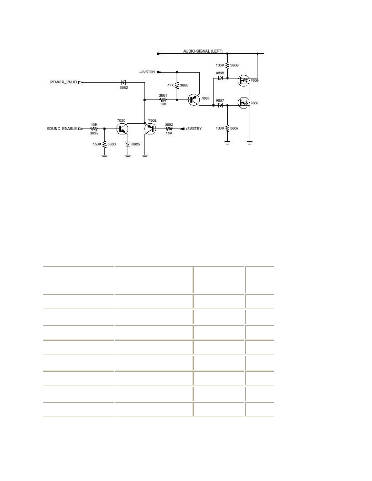
Figure: Audio mute circuitry
POWER_VALID(from
SOUND_ENABLE(from
+5VSTBY(from
SIGNAL
The table below shows how this is done. It is controlled by the following signals:
• "POWER_VALID" line is a control signal generated by the power supply.
• SOUND_ENABLE line is a control signal coming from the uP on the SSP.
• +5VSTBY line, from the Front panel.
Table: Truth Table Audio Mute
PSU)
uP on SSP)
Front Panel)
MUTED
0 0 0 1
0 0 1 1
0 1 0 1
0 1 1 1
1 0 0 1
1 0 1 0
1 1 0 1
1 1 1 1
Page 97
When the SOUND_ENABLE signal is high, the two N-channel FETs are conducting the
audio signal to the GND, and will mute the audio output.
Why are two FETs implemented? Because in a case of "no mute," and FET 7868
directly connected to ground, the diode in this FET would distort the audio signal too
much. With the addition of FET 7867, this distortion is eliminated, because this FET is
connected in anti-series.
The supply for the inverter is connected to the "+5VSTBY." This supply signal is always
available when the AC Power is connected, so in case the AC Power is disconnected,
the mute function is disabled.
UART
In total, four versions of the F21R Receiver box are realized. There is a USA/AP and a
EURO version (main difference is the HD part for USA and AP). Furthermore, there will
be version for the current 42" FTV1.9 monitor and a version for the new FM2x monitor
range. The difference between these versions is mainly the communication between the
Receiver box and monitor. See table below:
Table: Overview UART Diversity
Conn. 0303 F21R with FTV1.9 F21R with FM23
Pin 4 Not used RXDO
Pin 11 CONFIG_IDENT TXDO
Pin 12 TXDO Not used
Pin 15 RXDO Not used
The Receiver box has to support both the FTV1.9 and the FM2x plasma monitors. The
communication protocol for the FTV1.9 monitor is based on UART with a
CONFIG_IDENT signal. However, the FM23 and all new monitors will have a new
Page 98
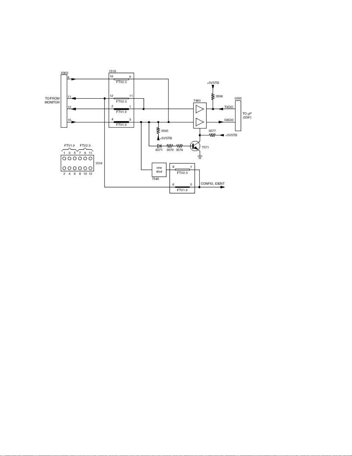
improved protocol called FSP (FTV System Protocol). Therefore, the pin layout on the
FTV monitor output connector has been changed.
Figure: Block Diagram UART Circuitry
As the FM2x has no CONFIG_IDENT signal to "wake up" the FTV2.1 Receiver box, a
"dummy" CONFIG_IDENT is derived from the RXDO signal with the aid of a "one-shot
generator" (item 7545).
In order to prevent the RXD-line from connecting to ground, a protection circuit is
added. This circuit puts the RXD-buffer into tri-state if the input is connected to ground
for more than 100 ms.
Because the diversity is realized with jumpers (connector 1519), there are no
differences in panel stuffing for both versions.
Page 99
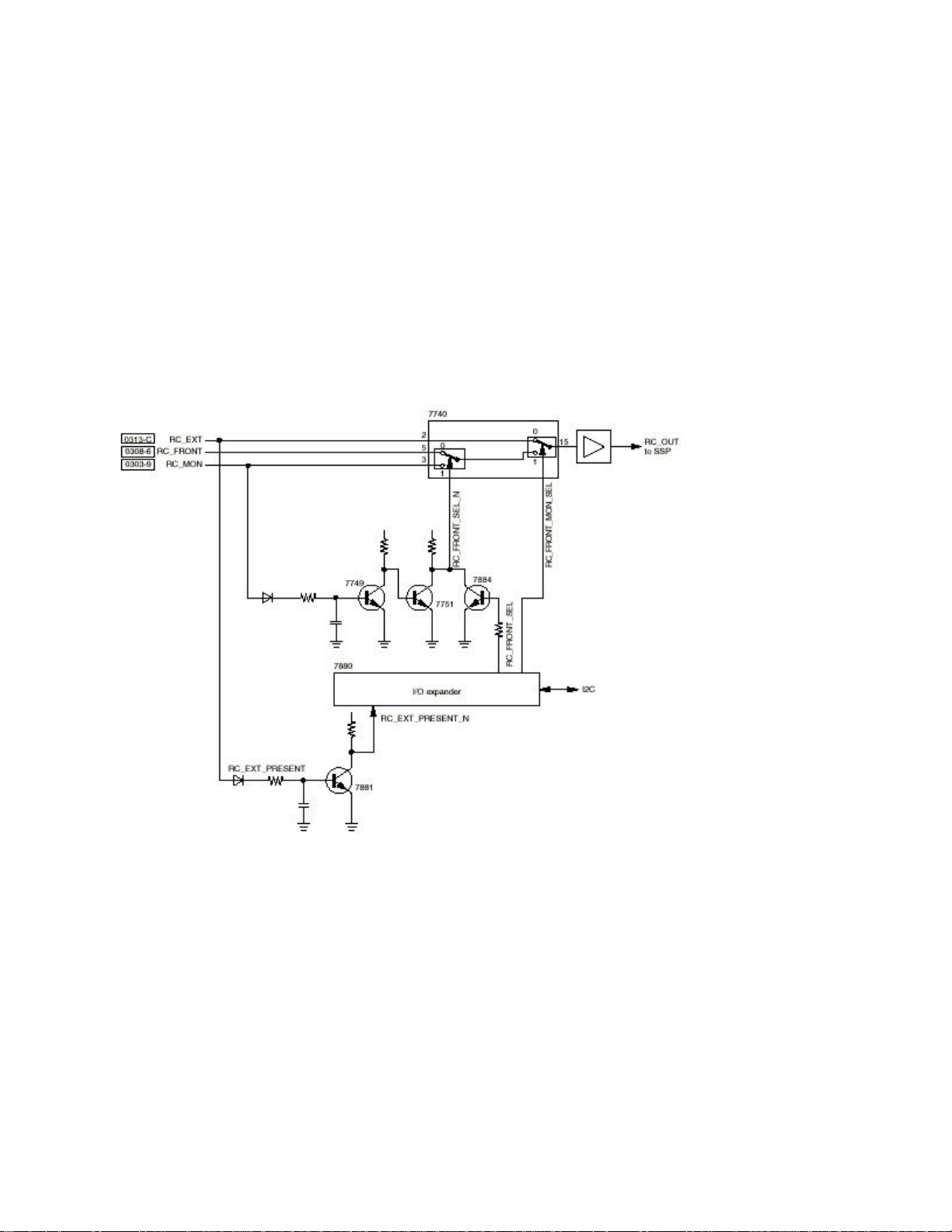
Remote Control
For the F21RU, there are three possible RC input sources:
• RC_MON (coming from monitor),
• RC_BOX (coming from box), and
• RC_EXT (coming from an external source; this is not used).
The selection is performed as shown in the figure below:
Figure: Block Diagram RC Selection Circuitry
If there is no monitor connected, RC_FRONT_SELECT is always "low," so RC _MON
cannot be selected (via TS7749 and TS7751). After start up, when the I/O-expander is
not yet set via I 2 C, the RC_FRONT signal is connected to RC_OUT.
Page 100
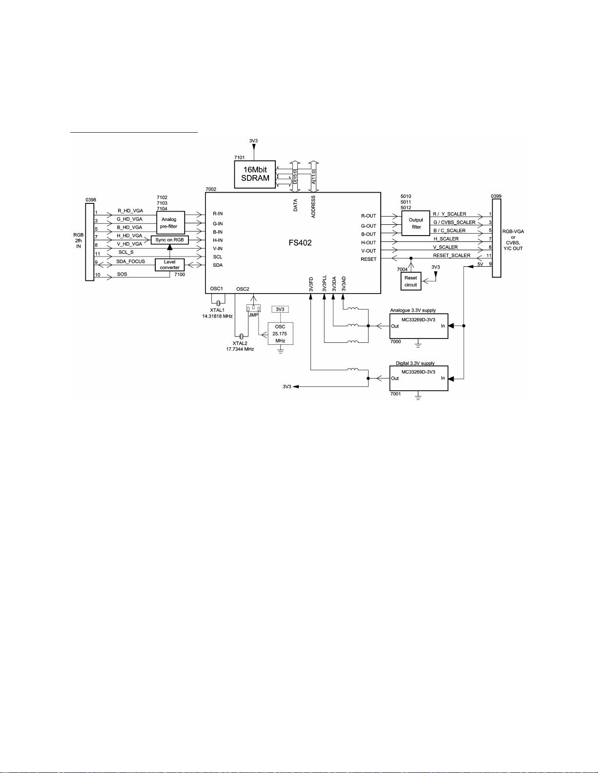
Down Scaler Panel (DS)
Down Scaler Panel (DS)
Introduction
The Scaler board has to process video signals from AV-interface board (analog RGB).
Its purpose is:
• To downscale incoming high resolution pictures (various VGA standards).
• To create the CVBS and Y/C output from VGA sources.
• To provide picture adjustments (brightness, contrast, and color saturation).
Notes:
1. The Scaler board is controlled via the system I 2 C bus. As the FS402 is not fully
compatible with the I 2 C protocol (it can misinterpret commands that are sent to
any other IC on the bus), the device is physically disconnected from the bus
 Loading...