

Philips FM1246 Datasheet

TUNERS
DATA SH EET
FM1246
Desktop video & FM radio module
system CCIR I
Preliminary specification
File under Tuners, DC03
1997 May 14

Philips Components Preliminary specification
Desktop video & FM radio module
system CCIR I
FEATURES
• System I and FM radio broadcast
• True 5 V device (low power dissipation)
• Full TV frequency range from channel A (45.75 MHz) to
channel 69 (855.25 MHz)
• FM radio band coverage from 87.50 to 108.00 MHz
• PLL controlled tuning
• Programmable PLL step size (31.25, 50 or 62.5 kHz)
• True-synchronous vision IF demodulator (PLL)
• Ultra-linear FM PLL demodulator for FM radio broadcast
• Demodulated video output, AF sound output, second
sound IF output
• I2C-bus control of tuning, address selection, AFC status
information
• Complies with European regulations on radiation, signal
handling and immunity
• Small horizontally mounted metal housing.
DESCRIPTION
The FM1246 front-end is designed to receive both TV and
FM stereo signals in the PC Multimedia environment. The
units are available with separate 75 Ω inputs for TV and
FM broadcast reception. The input connectors available
are either standard phono or IEC type (female for TV, male
for FM radio). The tuning, bandswitching and antenna
selection are made through the I
The front-end covers the TV bands from 45.75 MHz to
855.25 MHz. The FM band covers the standard
87.50 MHz to 108.00 MHz. An RDS decoder can be
connected to the AF-MPX output. The FM1246 meets the
input immunity and radiation requirements of CENELEC.
“CENELEC 55020, 55013’’
2
C-bus.
FM1246
In the FM radio mode, the level detector and AFT functions
are provide for the auto-search routines. The level detector
and AFT status can be read from the A/D bits in the
status-byte. The mute function is also provided to
suppress the audio output signal, if required.
The tuner AGC for both TV and FM radio operation, is
generated with a novel AGC detector which measures the
IF signal level directly at the tuner IF output pins. As
opposed to the conventional AGC detector, this new circuit
allows a higher take-over level and offers superior
immunity against tuner overload.
The demodulation of the TV sound and FM radio IF
(10.70 MHz) is done with a PLL demodulation circuit
contained in the IF IC. In the FM radio mode, the
multiplexed AF signal is then channelled to a stereo
decoder IC which extracts the left/right analog signals.
The multiplexed audio signal is also available at pin 25 to
support RDS implementations. The 2nd IF TV sound output
is provided to connect external (analog 2 carrier or digital)
stereo processing.
ORDERING INFORMATION
TYPE DESCRIPTION
FM1246/HM/PH standard phono 3139 147 13901
FM1246/HM/I IEC connector 3139 147 13911
CATALOGUE
NUMBERS
The FM1246 consists of a TV tuner, an FM radio tuner and
an IF section, all on a single PCB. The front-end is
assembled in a metal housing made of a rectangular
tin-plated steel frame, with front and rear covers, which
have soldered contacts to the frame. The two phono or
IEC antenna connectors (female for TV, male for FM
radio) are mounted on one side of the frame for the TV/FM
signal inputs. All other connections are made via pins at
the bottom.
The TV IF section uses an intercarrier SAW filter, followed
by a true-synchronous vision IF demodulator (PLL) IC. The
analog AFC voltage is fed to the 5-level A/D converter in
the PLL tuning IC, so that the AFC status can be read via
the I2C-bus.
1997 May 14 2
MARKING
The following items of information are printed on a sticker
that is on the top cover of the tuner:
• Type number
• Code number
• Origin letter of factory
• Change code
• Year and week code.

Philips Components Preliminary specification
Desktop video & FM radio module
FM1246
system CCIR I
INTERMEDIATE FREQUENCIES
SYSTEM
FREQUENCY
(MHz)
Picture carrier 38.90
Colour 34.47
Sound 32.90
NICAM 32.348
FM 10.70
PINNING
SYMBOL PIN DESCRIPTION
V
T
V
S(tuner)
11 tuning voltage (monitor)
12 supply voltage tuner section +5 V
SCL 13 I
SDA 14 I
AS 15 I
AF O/P right 20 FM radio right channel
AF O/P left 21 FM radio left channel
nd
2
IF O/P 22 second IF TV sound output
CVBS 23 Composite Video Baseband Signal (CVBS) output
V
S(IF)
24 supply voltage IF section +5 V
AF O/P 25 AF sound output
− TH1, TH2, TH3 and TH4 mounting tags (ground)
CHANNEL COVERAGE
BAND
FREQUENCY
(MHz)
FM radio band 87.50 to 108.00
Low band 45.75 to 170.00
Mid band 170.00 to 450.00
High band 450.00 to 855.25
2
C-bus serial clock
2
C-bus serial data
2
C-bus address select
1997 May 14 3
Philips Components Preliminary specification
Desktop video & FM radio module
system CCIR I
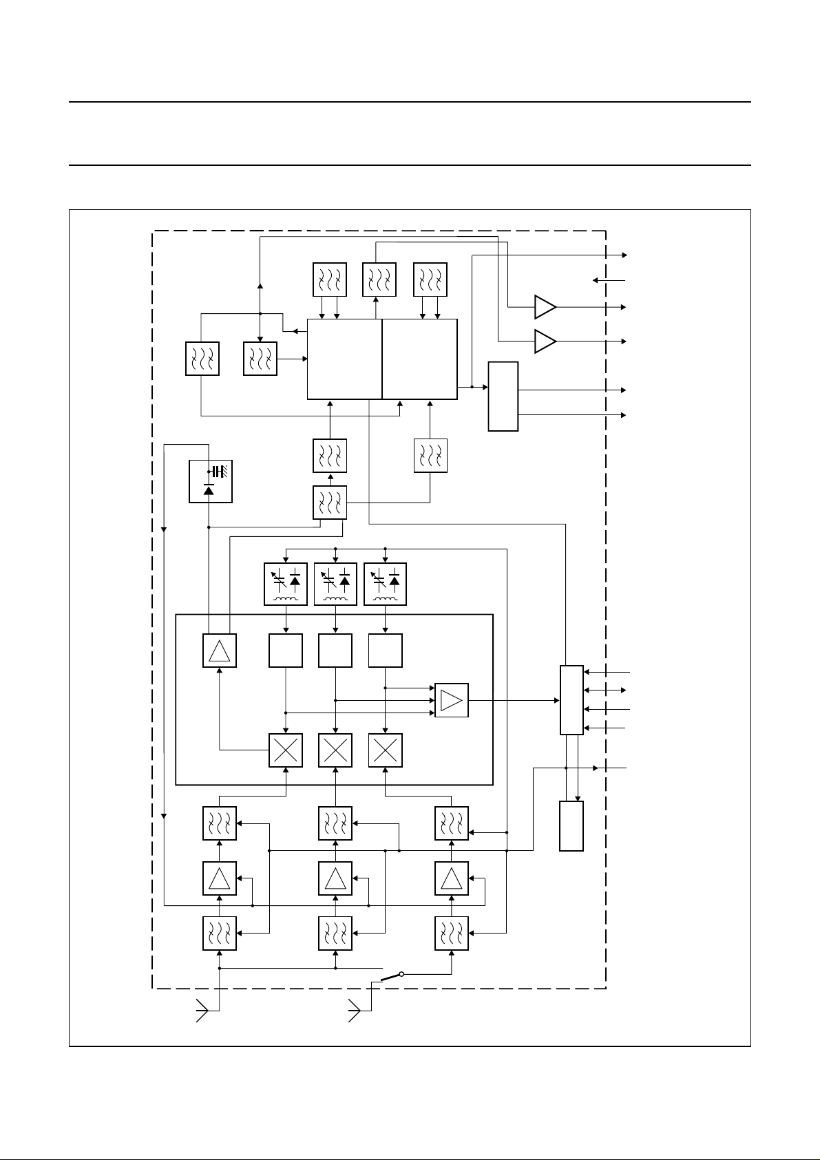
BLOCK DIAGRAM
2nd IF
FILTER
10.7 MHz
FILTER
AGC
DETECTOR
SAW
IF
V
VCO
PLL
VIF
DEMODULATOR
TRAP
FM
DEMODULATOR
FM-IF
10.7 MHz
DISCRIMINATOR
STEREO
DECODER
FILTER
10.7 MHz
FM1246
AF
(TV)
S(IF)
+5 V
V
CVBS
23
sound
output
2nd IF
AF-R AF-L
IF
MIXER - OSCILLATOR IC
HIGH BAND
OSC.
HIGH
MID
OSC.
MID BAND
LOW
OSC.
LOW BAND
VT
AFT
PLL
DC-DC
11 12 13 14 15 20 21 22 2524
CCA505
AS
SDA
SCL
+5 V
VT
S( tuner)
V
monitor
Fig.1 Electrical block diagram.
handbook, full pagewidth
TV
antenna
FM
antenna
1997 May 14 4

Philips Components Preliminary specification
Desktop video & FM radio module
FM1246
system CCIR I
LIMITING VALUES
Limiting values under operational conditions
The tuner can be guaranteed to function properly under the following conditions.
SYMBOL PARAMETER PIN MIN. TYP. MAX. UNIT
V
S
V
S(ripple)
I
S(tuner)
V
SCL
V
SDA
I
SDA
V
AS
V
AFright(FM)
Z
AFright(FM)
V
AFleft(FM)
Z
AFleft(FM)
Z
IF
Z
CVBS
t
L
V
S(IF)
I
S(IF)
Z
AF
supply voltage
peak-to-peak ripple voltage susceptibility
(at5V±5%); note 1
20 Hz to 100 kHz −−5mV
12
>100 kHz to 500 kHz −−10 mV
supply current −−120 mA
SCL bus input voltage 13 −0.3 − +5.25 V
SDA bus input voltage
SDA bus current (open collector) −1 − +5 mA
14
address select voltage; note 2 15 −−+5.25 V
FM right channel DC voltage
FM right channel load impedance parallel connected:
resistive value − 50 − kΩ
20
capacitive value − 9 − pF
FM left channel DC voltage
FM left channel load impedance:
resistive value − 50 − kΩ
21
capacitive value − 9 − pF
2nd IF sound output load impedance 22 0.5 −−kΩ
Composite Video Baseband Signal load impedance
CVBS load time constant −−100 ns
IF supply voltage
IF supply current −−150 mA
23
24
AF sound output load impedance parallel connected:
25resistive value 5.0 −−kΩ
capacitive value −−4nF
4.75 5.00 5.25 V
−0.3 − +5.25 V
− 1.0 − V
− 1.0 − V
− 75 −Ω
4.75 5.0 5.25 V
Notes
1. Sinusoidal ripple voltage superimposed on the 5 V supply voltage in the frequency range of 20 Hz to 500 kHz.
Criteria for TV interference >57 dB.
2. For detailed information about the address decoding, refer to Chapter “Application information”.
1997 May 14 5
Philips Components Preliminary specification
Desktop video & FM radio module
FM1246
system CCIR I
Environmental conditions
SYMBOL PARAMETER CONDITIONS MIN. TYP. MAX. UNIT
Non-operational conditions
T
amb
RH relative humidity −−100 %
g
B
g
S
Operational conditions
T
amb
RH relative humidity −−95 %
OVERALL PERFORMANCE
Conditional data
Unless otherwise specified, all electrical values for Chapter “Overall performance” apply at the following conditions.
ambient temperature −25 − +85 °C
bump acceleration 25 g −−245 m/s
shock acceleration 50 g −−490 m/s
vibration amplitude 10 to 55 Hz − 0.35 − mm
ambient temperature −10 − +60 °C
2
2
SYMBOL PARAMETER VALUE UNIT
T
amb
ambient temperature 25 ±5 °C
RH relative humidity 60 ±15 %
V
Z
Z
Z
t
pr
Z
S
CVBS
IF
AF
S(AE)
supply voltage (tuner and IF section) 5 ±0.125 V
video output load impedance (DC) 75 Ω
2nd IF sound output load impedance (DC) 0.5 kΩ
AF sound output load impedance 100 kΩ
pre-heating time (+5 V at pin 24) 10 minutes
aerial source impedance (asymmetrical) 75 Ω
1997 May 14 6

Philips Components Preliminary specification
Desktop video & FM radio module
FM1246
system CCIR I
TUNER CHARACTERISTICS
For detailed information about the PLL programming, refer to Chapter “Application information”.
The desktop video tuner is guaranteed to function properly within the specified operational conditions, but a certain
deterioration of performance parameters may occur at the limits of the operational conditions.
Required data for test equipment to be used
EQUIPMENT PARAMETER VALUE UNIT
DC voltmeter input impedance >1 MΩ
Oscilloscope input impedance:
resistance >1 MΩ
capacitance <15 pF
Spectrum analyzer input impedance 50 Ω
FET probe input impedance:
resistance 1 MΩ
capacitance 3.5 pF
output impedance 50 Ω
voltage gain 0 dB
AC millivoltmeter input impedance >100 kΩ
1997 May 14 7
Philips Components Preliminary specification
Desktop video & FM radio module
system CCIR I
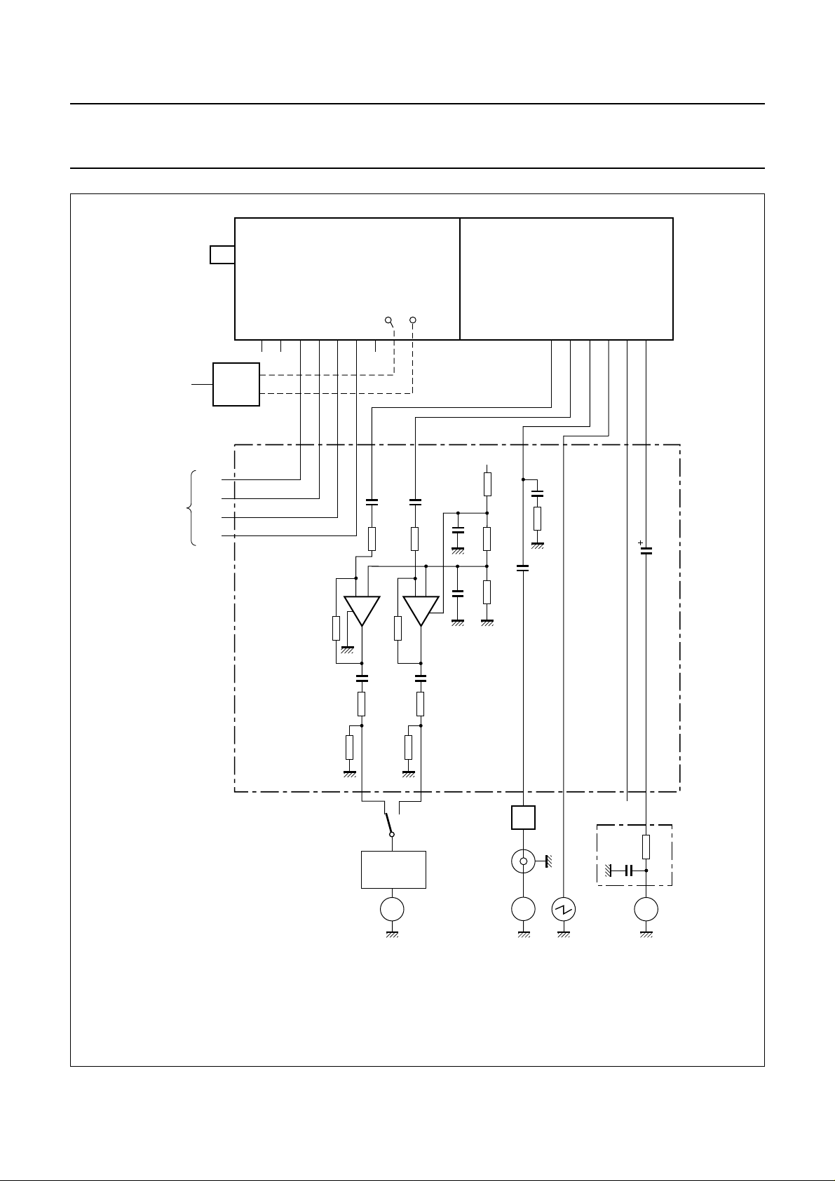
handbook, full pagewidth
IF
output
BU2
aerial
connector
V
T
V
S
SCL
SDA
IF
PROBE
OUT
11
1
/
TDA1308
2
12 13 14 15
240
kΩ
TP2 TP3
220
220
nF
nF
39
kΩ
563
2
240
kΩ
−
17
+
−
39
kΩ
+
84
1
/
TDA1308
2
+
+
µF
µF
FM1246
2120109 22 23 24 25
5 V
22
Ω
47
47
kΩ
47
1
kΩ
10
nF
kΩ
nF
3
1
33
µF
++
220
kΩ
47
µF
22
Ω
220
kΩ
47
µF
22
Ω
TEST JIG
CCA650
S1
15 kHz
LOW-PASS
FILTER
(1) BU4 loaded with 75 Ω.
(2) 50 µs de-emphasis.
SA = Spectrum Analyzer.
P = FET probe.
DA = Distortion Analyzer.
VAC = dual channel AC voltmeter (Zi= 600 Ω).
The minimum load impedance required at the CVBS output (pin 23) is 75 Ω (both AC and DC).
Fig.2 Typical test set up.
SA
BU6BU2BU4BU5BU8BU7
video
P
out
(1)
+5 V
10
nF
5
kΩ
(2)
DADA
1997 May 14 8
 Loading...