

Page 1
F-2200 Series Vortex
Flow Meter Installation and
Operation Guide
For software version CF 4.7 and higher
12-15-08
1500 North Belcher Road • Clearwater, FL 33765 • Tel (727) 447-6140 • Fax (727) 442-5699
www.onicon.com • sales@onicon.com
Page 2
SAFETY INFORMATION
i
This meter was calibrated at the factory before shipment. To ensure correct use of the meter, please read
this manual thoroughly.
Regarding This Manual:
• This manual should be passed on to the end user.
• Before use, read this manual thoroughly to comprehend its contents.
• The contents of this manual may be changed without prior notice.
• All rights reserved. No part of this manual may be reproduced in any form without
ONICON’s written permission.
• ONICON makes no warranty of any kind with regard to this material, including, but not
limited to, implied warranties of merchantability and suitability for a particular purpose.
• All reasonable effort has been made to ensure the accuracy of the contents of this manual.
However, if any errors are found, please inform ONICON.
• ONICON assumes no responsibilities for this product except as stated in the warranty.
• If the customer or any third party is harmed by the use of this product, ONICON assumes no
responsibility for any such harm owing to any defects in the product which were not
predictable, or for any indirect damages.
Safety Precautions:
The following general safety precautions must be observed during all phases of installation,
operation, service, and repair of this product. Failure to comply with these precautions or with
speci c WARNINGS given elsewhere in this manual violates safety standards of design, manufacture,
and intended use of the product. ONICON Incorporated assumes no liability for the customer’s
failure to comply with these requirements. If this product is used in a manner not speci ed in this
manual, the protection provided by this product may be impaired.
The following symbols are used in this manual:
WARNING
!
Messages identi ed as WARNING contain information regarding the personal safety of individuals
involved in the istallation, operation or service of theis product.
CAUTION
!
Messages identi ed as CAUTION contain information regarding the potential damage to the product
or other ancillary products.
Messages identi ed as IMPORTANT NOTICE contain information critical to the proper operation of
the product.
F-2200 Series Vortex Flow Meter Installation and Operation Guide • Revised 12/08
IMPORTANT NOTICE
3
Page 3
F-2200 Series Vortex Flow Meter Installation and Operation Guide
Addendum
December 12, 2008
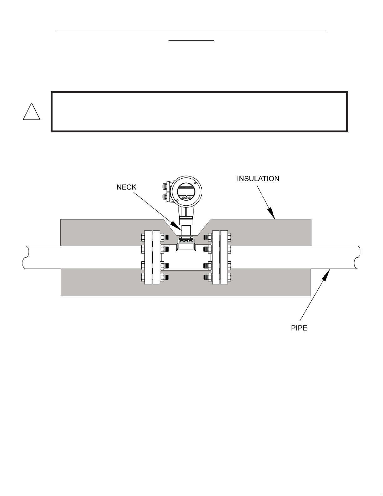
The drawing below illustrates the proper method for insulating the ow meter.
CAUTION
!
Insulating the entire neck of the ow meter will increase heat transfer to the electronics enclosure
and may in some cases cause premature failure of the electronics.
F-2000 SERIES STEAM FLOW METER WITH INSULATION DETAIL
F-2200 Series Vortex Flow Meter Installation and Operation Guide • Revised 12/08
4
Page 4

TABLE OF CONTENTS
1.0 INTRODUCTION ..............................................................................................................7
1.1 Purpose of This Guide .............................................................................................. 7
1.2 Principal of Operation .............................................................................................. 7
1.3 Features and Speci cations ...................................................................................... 7
1.4 Additional Required Materials ................................................................................. 9
1.5 Working Environment ............................................................................................... 9
1.6 Serial Number ........................................................................................................... 9
2.0 UNPACKING .................................................................................................................... 10
2.1 Checking That You Have Received Everything ..................................................... 10
3.0 INSTALLATION INFORMATION ................................................................................... 11
3.1 Site Selection ........................................................................................................... 11
3.1.1 Flow direction and meter position .............................................................. 11
3.1.2 Maximum allowable difference between inside of meter body and
the connecting pipe ...................................................................................... 12
3.1.3 Straight, unimpeded inlet and outlet runs .................................................. 13
3.1.4 Minimizing pipe vibration ........................................................................... 14
3.1.5 Locating the meter in a pipeline that runs parallel to a wall ..................... 14
3.1.6 State of medium ........................................................................................... 14
3.1.6.1 Liquid Applications ..................................................................... 14
3.1.6.2 Steam or compressed gas applications ........................................ 14
3.2 Mechanical Installation .......................................................................................... 15
3.2.1 Orient the display for convenient viewing ................................................. 15
3.2.1.1 Liquid applications ...................................................................... 15
3.2.1.2 Steam or compressed gas applications ........................................ 16
3.2.2 Flanged type connections to ANSI B16.5 (Schedule 40) ............................ 16
3.2.3 Temperature Measurements ......................................................................... 17
3.3 Wiring Terminations ............................................................................................... 17
4.0 START-UP & TROUBLESHOOTING .............................................................................. 18
4.1 Start Up .................................................................................................................... 18
4.2 Measurement Mode ................................................................................................. 18
4.3 Operating the Display ............................................................................................. 19
4.4 Error Handling ......................................................................................................... 20
4.5 Troubleshooting Hints............................................................................................. 21
5.0 FLOW STRAIGHTENER CATALOG SHEET .................................................................. 22
F-2200 Series Vortex Flow Meter Installation and Operation Guide • Revised 12/08
5
Page 5

F-2200 Series Vortex Flow Meter Installation and Operation Guide • Revised 12/08
6
Page 6
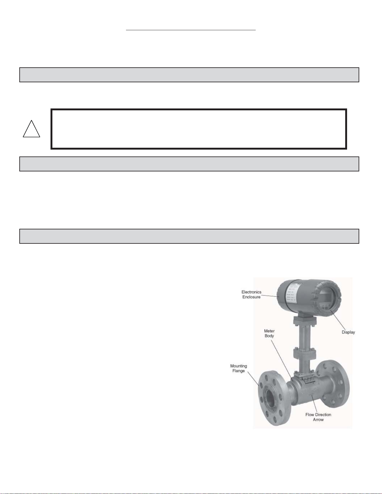
SECTION 1.0: INTRODUCTION
We, at ONICON INCORPORATED, would like to thank you for purchasing our F-2200 Series Vortex Flow
Meter. As our valued customer, our commitment to you is to provide fast reliable service and assistance,
while continuing to offer you new products to meet your growing ow measurement needs.
1.1 PURPOSE OF THIS GUIDE
The purpose of this guide is to provide installation and commissioning procedures and basic
operating and servicing instructions for ONICON F-2200 Series Vortex Flow Meters.
WARNING
!
Only quali ed service personnel should attempt to install or service this equipment. Serious injury
may result from the improper installation or use of this equipment.
1.2 PRINCIPAL OF OPERATION
ONICON F-2000 series vortex ow meters utilize Karman’s vortex street principal to detect changes
in velocity in the medium owing around the titanium shedder bar and through the meter body. A
volumetric ow rate is then derived by utilizing the known cross-sectional area of the meter body
and the average velocity of the medium. When provided with optional temperature and/or pressure
compensation the F-2000 series ow meters are capable of calculating the required density
corrections necessary to provide direct mass ow measurement of liquids, steam or gases.
1.3 FEATURES AND SPECIFICATIONS
CONSTRUCTION
Meter body:
Casting: 316 stainless steel for diameters up to 4”
304 stainless steel for 6” and 8” diameters
Shedder bar: Unalloyed titanium
Shedder bar seal: Ni plated Inconnel
Damper pin o-ring:
Viton for, non-steam, -4° to 356° F
Kalrez 4079 for, non-steam, -4° to 428° F
Paro uor for steam, -4° to 464° F
Electronics enclosure:
Enclosure material: Die-cast aluminum
Enclosure viewing window: Tempered glass,
UV blocking
CALIBRATION
Each meter undergoes a 5 point velocity calibration
from 0-250 ft/sec
PROGRAMMING
Each meter is programmed at the factory based on application speci c data provided by the
customer. Field re-programmable via keypad, with coded access for security.
F-2200 Series Vortex Flow Meter Installation and Operation Guide • Revised 12/08
7
Page 7

ACCURACY
Volumetric ow
±1% of reading accuracy (±2% for ¾” & smaller sizes)
Mass ow
±1.5% of reading accuracy (±2.5% for ¾” & smaller sizes)
OPERATING TEMPERATURE RANGE
Media temperature
25° to 464° F
Ambient temperature
0° to 132° F
DISPLAY / USER INTERFACE
16x64 dot matrix LCD with 3 button keypad and magnetic pin programming
OUTPUT SIGNALS
Rate: 4-20mA, loop-powered
Supply voltage range: 14-36 VDC
Minimum load resistance: 100 ohms
Maximum load resistance is calculated as follows:
Max load = Vs – 12V Where Vs = supply voltage
0.020A
Total: Scaled output pulse, programmable
Optically isolated open collector, 0.5 hz maximum
Rating: 5-36 VDC, 100mA maximum
SUPPLY VOLTAGE:
14-36 VDC
PROCESS CONNECTIONS:
Standard: ANSI #300 anges
Optional: ANSI #600 anges
APPROVALS
Safety: Conforms to CE mark as per LVD, PED and EMC Directive
Enclosure: Conforms to IP 65 and IP 67
F-2200 Series Vortex Flow Meter Installation and Operation Guide • Revised 12/08
8
Page 8

1.4 ADDITIONAL REQUIRED MATERIALS
Installer is responsible for providing suitable anges and fasteners to connect the meter to the
process piping. In addition, most installations will also require one reducer, one expander, pipe
supports and a suf cient length of straight pipe (pipe diameter = meter size) to meet the installation
requirements outlined in this manual. Use of an optional ow recti er may be required in cases
where the available space is not suf cient to allow for proper upstream straight pipe run.
1.5 WORKING ENVIRONMENT
ONICON F-2000 series vortex ow meters are designed for use in industrial environments that are
free of corrosive liquids, fumes and excessive vibration. Do not expose the ow meter electronics
enclosure to direct sunlight. Install a sunshade if necessary. Do not expose the ow meter to intense
vibration. If necessary, provide additional support to the pipeline, at the meter location, to minimize
vibration. The rotating design of the electronics enclosure makes it easier to connect the power and
signal cables to the terminals in the rear of the enclosure. Rotate the enclosures as necessary before
installing the meter.
The ambient operating temperature range is 0° to 132° F.
1.6 SERIAL NUMBER
The serial number for your F-2000 series vortex ow meter is located on the metal identi cation
plate mounted on the side of the electronics enclosure. Please have this number available whenever
you contact ONICON for assistance.
F-2200 Series Vortex Flow Meter Installation and Operation Guide • Revised 12/08
9
Page 9

SECTION 2.0: UNPACKING
F-2000 series vortex ow meters are shipped in one package. Additional items, if ordered, will be shipped
in separate packaging. All shipments are insured for damage in transit. Carefully inspect each package and
notify the freight carrier and ONICON immediately if any items arrive damaged.
2.1 ENSURING THAT YOU HAVE RECEIVED EVERYTHING
Standard Documentation
Each ONICON ow meter is serialized and supplied with a comprehensive documentation
package speci cally prepared for this meter. It includes the following items. Please notify
ONICON immediately if any discrepancies are found.
• Flow Meter
• The F-2000 Vortex Flow Meter Installation and Operation Guide
• The Flow Meter Calibration Data Sheet
• Magnetic programming pin
F-2200 Series Vortex Flow Meter Installation and Operation Guide • Revised 12/08
10
Page 10

SECTION 3.0: INSTALLATION INFORMATION
The F-2000 series vortex ow meter must be installed by a technician quali ed to work with pressurized
liquid, steam and/or gas ow and must conform to all federal, state and local building codes. ONICON will
be happy to assist with technical recommendations and to provide guidance via telephone or mail. On-site
engineering, installation and service are also available, at additional cost.
3.1 SITE SELECTION
Careful attention in locating the point in the piping system where the ow meter will be installed
will ensure accurate and reliable operation. When selecting an installation site, consider the criteria
contained in Section 1.5 WORKING ENVIRONMENT, as well as the following:
CAUTION
!
3.1.1 Flow Direction And Meter Position
The installation guidelines presented below are minimum requirements for the proper operation of
this ow meter.
The ow must always be in the direction of the arrow located on the meter body.
This will orient the bluff side of the vortex shedder bar so that it faces the incoming
ow (i.e. the upstream side).
For vertical pipe runs, ow must always be in the upward direction. Consult the
factory in the event that a downward owing pipe is the only available location.
F-2200 Series Vortex Flow Meter Installation and Operation Guide • Revised 12/08
11
Page 11

The diagrams shown below illustrate the correct meter orientation for vertical and horizontal pipe.
3.1.2 Maximum Allowable Difference Between Inside Diameter Of Meter Body
And The Connecting Pipe
The table below provides the maximum allowable difference between the diameter of
the ow meter body and the connecting pipe.
Nominal Meter Size
(in.)
1” 1.05 0.016
1 1/2” 1.61 0.016
2” 2.07 0.024
3” 3.07 0.024
4” 4.03 0.024
6” 6.07 0.031
8” 7.98 0.039
Meter Body
Diameter (in.)
Maximum Pipe ID
Difference (in.)
Ensure that the bore of the locating pipes are smooth and without deposits,
scaling, or welding beads.
F-2200 Series Vortex Flow Meter Installation and Operation Guide • Revised 12/08
12
Page 12

3.1.3 Straight, Unimpeded Inlet And Outlet Runs
D = Meter Size (Nominal diameter in inches)
With a ow straightener, the inlet pipe length may be reduced by 50%. For example, with a
control valve upstream, the inlet length is 25D instead of 50D. The minimum inlet pipe length
including the ow straightener must always be at least 12D.
3.1.4 Minimizing Pipe Vibration
Pipe vibration caused, for example, by the action of pumps, valves, etc. will distort ow
measurements, particularly at low ow velocities. To minimize the effects of vibration,
support the pipeline on both sides of the meter in a direction perpendicular to both the
pipeline and the shedder bar axis.
F-2200 Series Vortex Flow Meter Installation and Operation Guide • Revised 12/08
13
Page 13

3.1.5 Locating The Meter In A Pipline That Runs Parallel To A Wall
Wherever possible, the distance between the pipe centerline and the wall should be greater
than 20”. This will allow for access to the electronics enclosure compartment where wire
terminations are made. If adequate space is not available, rst connect all the cables to the
terminals in the connection compartment (power supply and outputs) and then run the wires
to an intermediate junction box (also see Section 3.2) before installing the meter.
3.1.6 State Of Medium
In all cases the meter requires a single-phase ow for proper operation. Liquid droplets in
the gas or vapor, solid particles in the gas or liquid and gas bubbles in the liquid are not
permitted.
3.1.6.1 Liquid Applications
When operating with liquids, the meter requires a minimum downstream pressure
to prevent cavitation. The formula used to determine the minimum downstream
pressure is as follows:
Pds(bar_g) > =(2.9*DP) + (1.3*Ps)-1.013
Where DP=pressure drop of the meter, in Bar, as determined by the ONICON sizing
program and Ps=saturation pressure, in Bar, at the operating temperature.
For any uid, a lter or strainer may be used to remove the solid particles. This is
especially important for meter sizes below 1” where a lter or a strainer is required.
3.1.6.2 Steam Or Compressed Gas Applications
In case of steam or compressed gas, a moisture separator should be used 50D
upstream of the meter if the dryness fraction is less than 95%.
IMPORTANT NOTE
i
Steam quality will affect the accuracy of the measurement. It is strongly recommended that a moisture
separator be installed upstream of the inlet straight pipe run for anything less than 95% dry steam.
F-2200 Series Vortex Flow Meter Installation and Operation Guide • Revised 12/08
14
Page 14
3.2 MECHANICAL INSTALLATION
3.2.1 Orient The Display For Convenient Viewing
Both the electronics enclosure and the display itself can be rotated to four different
orientations to change the viewing angle for the display. If necessary, this should be done
before the meter is installed.
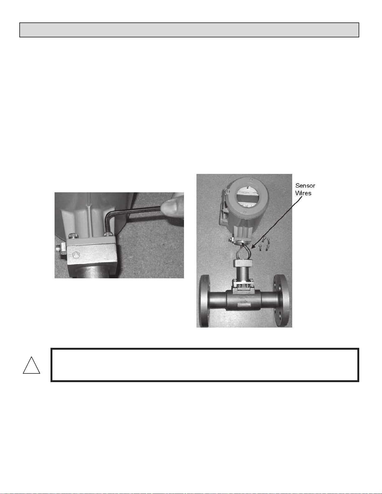
3.2.1.1 Rotating the electronics enclosure
The electronics enclosure is attached to the meter body with (4) 5mm Allen head
screws. To rotate the enclosure, you must rst remove the screws and then carefully
rotate the enclosure as needed. The interconnecting stem assembly is a conduit for
wires that connect the sensors to the circuitry contained in the enclosure. Care must
be taken to prevent these wires from being damaged when rotating the enclosure.
!
CAUTION
Make certain the sensor wires are not damaged when re-attaching the enclosure.
F-2200 Series Vortex Flow Meter Installation and Operation Guide • Revised 12/08
15
Page 15

3.2.1.2 Rotating the display
To rotate the display, rst unscrew the cover using the special tool provided for this
purpose. Once the cover is removed, the (4) Philips head screws that secure the
display are exposed. To rotate the display, remove these screws and carefully move it
to the desired position making certain that the interconnecting cable is not damaged
in the process.
CAUTION
!
• Do not remove enclosure covers in any wet environment
• Keep dirt and debris out of electronics enclosure
• Keep threads lubricated (silicone based lubricant)
• Do not over tighten covers. Use special tool for removal only.
3.2.2 Flanged-Type Connection To Ansi B16.5 (Schedule 40)
Meter sizes
3/8”, 1/2”, 3/4”, 1”, 1 1/2”, 2”, 3”, 4”, 6”, 8”
Pipe anges
To ANSI: #300 standard,
#600 optional
Gaskets are supplied with anged units.
Center the ow meter by sight.
Check the ange connections for leak-tightness
after the ow meter installation.
F-2200 Series Vortex Flow Meter Installation and Operation Guide • Revised 12/08
16
Page 16

3.3.2 Temperature Measurements
ONICON F-2000 series vortex meters are supplied with an internal PT 1000 type RTD
temperature sensor located within the shedder bar. This sensor provides an accurate
temperature measurement at the point where the ow rate is being measured. Flow meters
supplied with this option will display the medium temperature and deliver an output signal
that is temperature compensated for mass and/or normalized ow.
3.3 WIRING TERMINATIONS
The standard F-2000 series vortex meter is a 2-wire loop powered device. Wiring connections are shown
below.
CAUTION
• Do not remove enclosure covers in any wet environment
!
• Keep dirt and debris out of electronics enclosure
• Keep threads lubricated (silicone based lubricant)
• Do not over tighten covers. Use special tool for removal only.
4-20 mA
100 ohms
minimum
F-2200 Series Vortex Flow Meter Installation and Operation Guide • Revised 12/08
17
Page 17

SECTION 4.0: START UP AND TROUBLESHOOTING
i
4.1 START UP
When the power is applied to the F-2000 series vortex meter, alphanumeric characters will appear
on the display. Initially, the meter will operate in a “TEST” mode where self diagnostic checks are
performed on the pre-ampli er and sensor circuits. Following this, con guration data is loaded
from the non-volatile memory and the program advances to the measurement mode.
IMPORTANT NOTE
i
!
4.2 MEASUREMENT MODE
In the measurement mode, the display
indicates real-time ow, temperature and/
or pressure data in the appropriate units.
The top line of the display indicates the
current measured value. The second line
of the display indicates the programmed
units of measurement.
There are two options for displaying data in
the measurement mode. The display may
be set to automatically scroll through each
menu page or it may be set to manually step
through the menu pages using the up arrow
key to advance each page. Displays operating
in the cyclic mode will advance through
each page every 6 seconds.
The meter should be installed and powered for at least 15 minutes before media is allowed to ow
through the meter.
Flow velocity through the meter should be increased gradually until full ow is achieved.
CAUTION
IMPORTANT NOTE
When measuring steam ow, condensate may form on the cool surfaces of the meter and piping
system when the system is started up for the rst time (causing faulty measurement).
F-2200 Series Vortex Flow Meter Installation and Operation Guide • Revised 12/08
18
Page 18

4.3 OPERATING THE DISPLAY
i
Please read the entire procedure before proceeding. Wiring diagrams are located in the Appendix. A
worksheet for checking off the following steps and recording measured values is located on the next
page.
key Hall
Eect Switch
key Hall
Eect Switch
key Hall
Eect Switch
Display page scroll
(measurement mode)
IMPORTANT NOTE
Do not attempt to enter the program mode without rst contacting ONICON service.
There are 3 user interface switches located immediately below the display. Each switch performs a
separate function. The table below describes the function of each switch. There are also 3
corresponding Hall Effect switches that perform the same functions. The Hall Effect switches may be
activated without removing the display cover, using the magnet provided with the meter. Place the
magnet against the cover in proximity to the Hall Effect switch to activate.
!
CAUTION
• Do not remove enclosure covers in any wet environment.
• Keep dirt and debris out of electronics enclosure.
• Keep threads lubricated (silicone based lubricant).
• Do not over tighten covers. Use special tool for removal only.
F-2200 Series Vortex Flow Meter Installation and Operation Guide • Revised 12/08
19
Page 19

4.4 ERROR HANDLING
The meter can detect errors in either the test or the measurement modes. When in the measurement
mode, a blinking vertical bar will appear in the top left corner of the display indicating an error has
been detected. If the error reporting function is enabled, error messages will be displayed as separate
menu pages. The rst line of the error menu page indicates the total number of errors and the second
line displays the error message. Measurement mode error messages are listed below.
Error Message
(display second line)
NO SIGNAL No signal from the vortex
LOW FREQ. Vortex frequency is too low Check for fl ow rate lower than specifi ed mini-
HIGH FREQ. Vortex frequency is too high Check for fl ow rate higher than specifi ed maxi-
LOW FLOW Flow rate lower than speci-
HIGH FLOW Actual fl ow rate higher than
INV. CONFIG. Confi guration data in non-
ISO FAIL Checked
AMP FAIL Pre-amplifi er section has
PIEZO FAIL Piezo wires broken Contact ONICON.
CHECK INST Flow signal quality is bad Check: 1) Flow rate, if OK; 2) Check for
LOW SIGNAL Vortex signal amplitude too
HIGH SIGNAL Vortex sensor signal
LOW.TEMP.PHY. Operating temperature is
HIGH.TEMP.PHY. Operating temperature is
T.SENS.SHORT Temperature sensor/wires
T.SENS.OPEN Temperature sensor open
during
power-
on only
Type Description Corrective Action
Required
No fl ow. Also check for any other errors dur-
sensor
fi ed range
specifi ed range
volatile memory is not valid
Sensor isolation has failed Contact ONICON.
failed
low
amplitude too high
lower than the physical limit
higher than the physical limit
short circuit
circuit
ing power-on diagnostics. If there is a sensor
problem, contact ONICON.
mum. Contact ONICON.
mum. Contact ONICON.
Converter will continue to display actual fl ow
rate. However, accuracy of measurement may
suffer.
Corrective action depends on application process. If the fl ow rate exceeds the maximum
value it may damage the sensor physically.
Contact ONICON.
Contact ONICON.
excessive pipe vibration and upstream fl ow
disturbances; 3) Contact ONICON.
Check: 1) Flow rate, if OK; 2) Contact ONICON.
This occurs in cases of high density medium.
Check 1) Flow rate, if OK 2) Contact ONICON.
Take corrective action depending on the process.
Take corrective action immediately. This will
cause damage to the shedder bar as well as
to the electronics.
Indicates a fault in the temperature sensor.
Contact ONICON.
F-2200 Series Vortex Flow Meter Installation and Operation Guide • Revised 12/08
20
Page 20

4.5 TROUBLESHOOTING HINTS
REPORTED
PROBLEM
A non-zero fl ow indi-
cated when no actual
fl ow is in the pipe.
“CHECK INST.” error
is displayed when no
fl ow is in the pipe.
POSSIBLE
SOLUTIONS
• Mains interference due to improper Earth ground connection. The protective
Earth PE terminal should be properly grounded (see page 17).
• Excessive mechanical vibration in the pipe. If so, support the pipeline near the
meter perpendicular to both the axis of the pipe and the axis of the shedder
bar.
• This problem may also be solved by reducing the factory set gain. (Contact
ONICON for assistance.)
NOTE: By reducing the gain, the minimum measurable fl ow rate will go up
by the factor which is approximately equal to the square root of the gains
(odd gains new gain). If the minimum fl ow with reduced gain is above the
minimum fl ow which is required to be measured, then reducing the gain is
not the permanent solution. Then the installaion should be corrected and
also the vibrations should be eliminated.
The display should normally indicate 0.0 fl ow rate, LOW FLOW or LOW SIGNAL
when there is no fl ow in the pipe. The additional CHECK INSTALL error (fl ow
rate = 0.0 or some steady or fl uctuating value) is an indication of:
• Improper/inadequate earthing
• Excessive pipe vibration
Flow rate inidcated is
0.0 even with fl ow in
the pipe.
The fl ow indicated
responds to changes
in the fl ow but the
indicated value does
not correspond to the
actual fl ow rate. Also
“CHECK INST.” Error
may appear intermittently.
• The vortex sensor cable is disconnected or is not properly connected.
• Flow sensor is faulty. Contact ONICON for assistance.
• The meter is not properly centered on the pipeline. The axis of the meter bore
should be aligned with that of the pipe.
• Gaskets at the meter are protruding into the pipe bore. The gaskets must not
project into the effective cross-section of the pipe.
• Irregularities on the surface of the pipe bore. The pipe bore should be free from
irregularities at the welded joints, dirt, deposits and excessive surface roughness.
• The Vortex signal is distorted due to a bi-phase medium. Bi-phase media are
not permitted. Use a moisture separator for wet steam applications to remove
the moisture droplets from the steam. Use suitable fi lters in gas applications to
remove solid particles from the fl owing gas. • Incorrect angular position of the
meter. Refer to Section 3.1.1 for the allowable mounting positions.
• Insuffi cient upstream/downstream pipe lengths. Check that the upstream/
downstream pipe lengths are of the correct minimum length as given in
Section 3.1.3.
• Error in meter factor K-Factor programming. Contact ONICON for assistance.
• Check that the fl ow direction and the direction arrow on the meter body agree.
F-2200 Series Vortex Flow Meter Installation and Operation Guide • Revised 12/08
21
Page 21
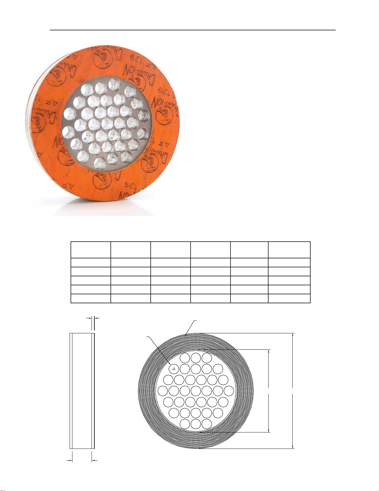
SECTION 5.0: FLOW STRAIGHTENER FOR VORTEX FLOW METERS
DESCRIPTION
The optional ow straightener accessory for
ONICON F-2000 Series Vortex Flow Meters is a
wafer-style ow conditioner that is designed to be
installed between two recessed anges (provided
by installer) that are located a speci ed distance
upstream of the ow meter.
Use of a ow straightener signi cantly reduces the
upstream straight pipe length requirement for
ONICON Vortex Flow Meters.
The size of the straightener should always match
the meter size (as opposed to the original pipe size).
The ow straightener is made of 304/A 351 CF8
stainless steel.
TABLE 1 - ALL DIMENSIONS SHOWN IN INCHES
SIZE DIM A DIM B DIM C DIM D NUMBER OF
HOLES
2” 3.93 1.0625 .28 2.14 35
3” 5.31 1.0625 .43 3.24 35
4” 6.26 1.0625 .55 4.22 35
6” 8.50 1.0625 .78 6.07 35
8” 10.62 1.0625 1.02 7.98 35
0.125
GASKET THICKNESS, NOMINAL
DIM C
SERRATIONS SHOWN LOCATED UNDER GASKET, IF PROVIDED
NOTE: DIMENSION D INDICATES I.D. FOR SERRATIONS
DIM D DIM A
0497
DIM B
F-2200 Series Vortex Flow Meter Installation and Operation Guide • Revised 12/08
22
8-06
Page 22

ECCENTRIC REDUCER, NOTE 2
UPSTREAM
OBSTRUCTION
SEE TABLE 1
BALL/GATE VALVE FULLY
TWO 90’S OUT OF PLANE 22 DIA 20 DIA
ONICON F-2000 SERIES STEAM METER, NOTE 1
FLOW STRAIGHTENER, NOTE 3
DIMENSION B 2 DIAMETERS 5 DIAMETERS
MINIMUM UPSTREAM PIPE RUN
DIMENSION A
MINIMUM DOWNSTREAM PIPE RUN
REQUIRED DIMENSIONS FOR INSTALLATIONS WITH FLOW STRAIGHTENER
DIMENSION A DIMENSION B
UPSTREAM
OBSTRUCTION
TOTAL UPSTREAM
PIPE RUN
DISTANCE BETWEEN
FLOW METER AND
STRAIGHTENER
SINGLE 90 12 DIA 10 DIA
TEE 12 DIA 10 DIA
RDCR/EXPNDR 12 DIA 10 DIA
TWO 90’S SAME PLANE 17 DIA 15 DIA
17 DIA 15 DIA
OPEN
CONTROL VALVE 27 DIA 25 DIA
PRV 27 DIA 25 DIA
300# ANSI FLANGE
(600# ANSI FLANGE OPTNL)
NOTES
1. Consult ONICON for meter size and applicable meter pipe run for each application. Install
according to manufacturer’s recommendations.
2. Provide eccentric reducer and expander when required.
3. Provide fl ow straightener when required to meet recommended minimum upstream pipe run
requirements.
4. Flanges provided by contractor. Recessed fl anges are required for wafer fl ow straightener
installation.
F-2200 Series Vortex Flow Meter Installation and Operation Guide • Revised 12/08
23
 Loading...