

Page 1
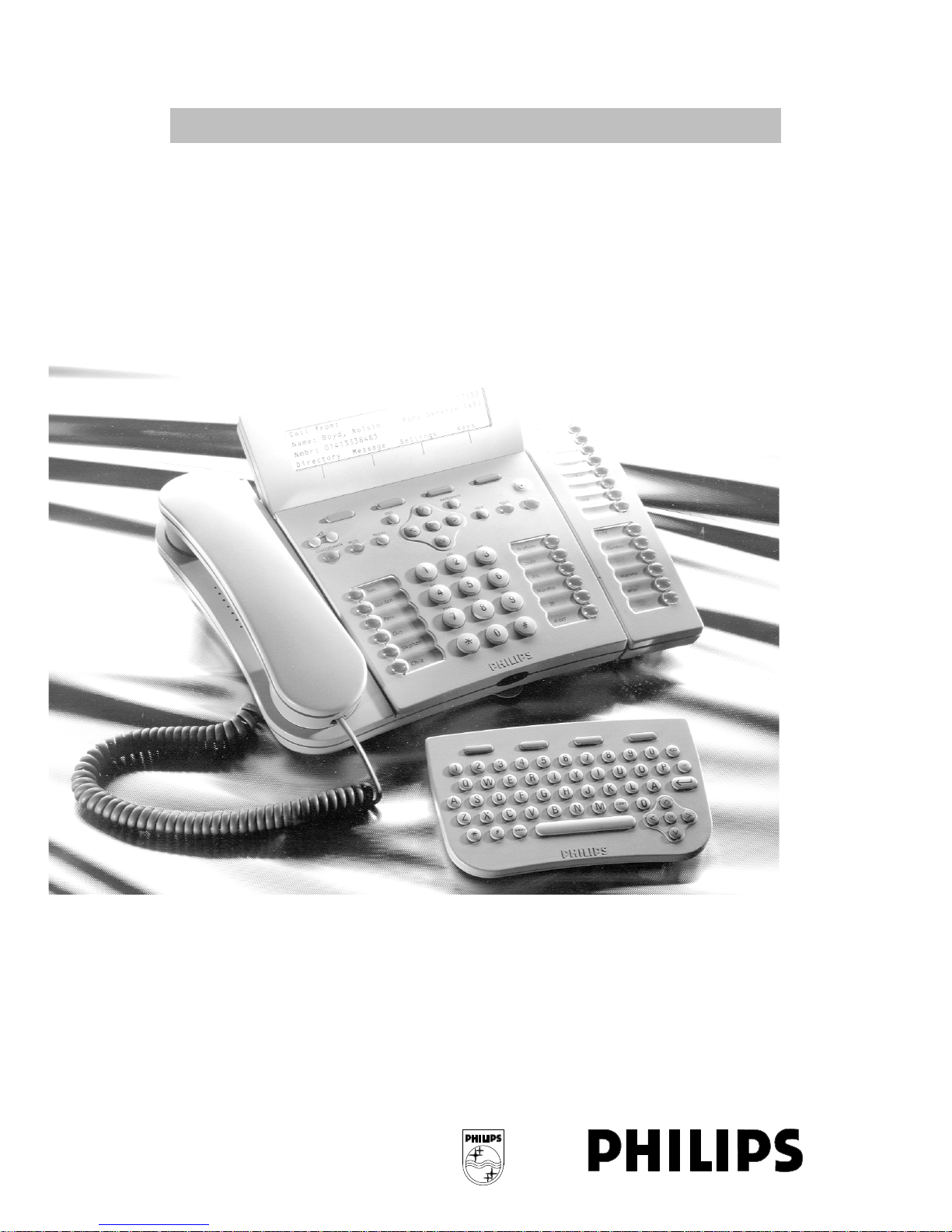
ErgoLine D330/D340/D310/D320
Customer Engineer Manual
Page 2

3513 302 60092
February 1999
Page 3

ErgoLine D330/D340
Customer Engineer Manual
i
C
ONTENTS
I
NTRODUCTION
............................................................................................1-1
Features
..................................................................................................1-1
ErgoLine D330.........................................................................................1-1
User Features..........................................................................................1-1
Keys.........................................................................................................1-2
Interfaces................................................................................................1-2
Variants...................................................................................................1-2
ErgoLine D340.........................................................................................1-3
User Features..........................................................................................1-3
Keys.........................................................................................................1-3
Interfaces................................................................................................1-4
Options ...................................................................................................1-4
Variants...................................................................................................1-4
Quick Scan Card of ErgoLine Models
...................................................1-5
Physical Layout
......................................................................................1-7
Description of Functions
........................................................................ 1-10
Numeric Keys..........................................................................................1-10
Programmable Keys..............................................................................1-10
Fixed Function Keys................................................................................1-10
Cursor Keys.............................................................................................1-10
Soft Keys (D340)......................................................................................1-11
2x24 Display (D330)................................................................................1-11
4x40 Display (D340)................................................................................1-11
Loudspeaker ..........................................................................................1-12
External Microphone.............................................................................1-12
2-Wire/4-Wire Line Interface..................................................................1-12
PC Interface...........................................................................................1-12
Handset Cord Socket............................................................................1-12
Software Hatch......................................................................................1-12
Audio Socket (D340)..............................................................................1-12
Static Interface Socket (D340) ..............................................................1-12
Optional Power Supply (D340)..............................................................1-12
DSS Connector Cover (D340)................................................................1-13
V.24 Data Option...................................................................................1-13
Infra-Red ASCII Keypad Port.................................................................1-13
I
NSTALLATION
..............................................................................................2-1
Unpacking
..............................................................................................2-1
ErgoLine D330.........................................................................................2-1
ErgoLine D340.........................................................................................2-1
Power Supply
..........................................................................................2-1
Page 4

ErgoLine D330/D340
Customer Engineer Manual
ii
Cabling
...................................................................................................2-2
Power Cord............................................................................................2-2
Handset Cord.........................................................................................2-2
Terminal Line Cord.................................................................................2-2
PNT1 ........................................................................................................2-3
S
o
Interface.............................................................................................2-3
U
PN
Interface ...........................................................................................2-3
Cable and Distances.............................................................................2-4
Connecting the D330 ErgoLine Terminal
..............................................2-6
D330 Terminal Endpoint Identification (TEI)
..........................................2-7
Connecting the D340 ErgoLine Terminal
..............................................2-8
D340 Terminal Endpoint Identification (TEI)
..........................................2-9
System Requirements
............................................................................. 2.11
Preparing Download Information
.......................................................... 2-12
V.24 Port Characteristics .......................................................................2-12
Function Key Data.................................................................................2-12
Function Key Layout..............................................................................2-14
Facility Codes and Local Functions......................................................2-17
System Preconditions.............................................................................2-19
Downloading Examples.........................................................................2-26
Optional Interfaces
................................................................................ 2-29
Audio Interface......................................................................................2-29
Static Interface.......................................................................................2-30
V.24 Interface Option............................................................................2-31
PC Interface Option ..............................................................................2-39
Installing the DSS Options ......................................................................2-40
Installing Optional Line Interface..........................................................2-41
ASCII Keyboard......................................................................................2-42
International Character Selection........................................................2-43
Function Key Numbering.......................................................................2-44
P
ROGRAMMING TELEPHONE PARAMETERS
.........................................................3-1
ErgoLine D330 Programming Map........................................................3-1
ErgoLine D340 Programming Map........................................................3-2
Terminal Locking and Unlocking of the D330/D340.............................3-3
M
AINTENANCE AND TESTING
..........................................................................4-1
Selecting a Test ......................................................................................4-1
Show Software Version..........................................................................4-2
Display Test.............................................................................................4-2
Keyboard Test........................................................................................4-2
LED Test...................................................................................................4-2
Memory Test...........................................................................................4-3
EEPROM Erasure.....................................................................................4-3
Analogue Interface Test........................................................................4-3
Digital Interface Test..............................................................................4-4
Call Progress Codes...............................................................................4-5
Page 5

ErgoLine D310/D320
Customer Engineer Manual
i
C
ONTENTS
I
NTRODUCTION
............................................................................................5-1
Features
..................................................................................................5-1
ErgoLine D310.........................................................................................5-1
User Features..........................................................................................5-1
Keys.........................................................................................................5-1
Interfaces................................................................................................5-1
Accessories.............................................................................................5-1
ErgoLine D320.........................................................................................5-2
User Features..........................................................................................5-2
Keys.........................................................................................................5-2
Interfaces................................................................................................5-2
Accessories.............................................................................................5-2
Maintenance.........................................................................................5-2
Quick Scan Card of ErgoLine Models D310 and D320
........................5-3
Physical Layout
......................................................................................5-4
Description of Functions
........................................................................5-4
I
NSTALLATION
..............................................................................................5-5
Cabling
...................................................................................................5-5
Handset Cord.........................................................................................5-5
Terminal Line Cord D310-2W, D320-2W, D320-4W................................5-5
Terminal Line Cord D310-4W .................................................................5-5
PNT1 ........................................................................................................5-6
S
o
Interface.............................................................................................5-6
U
PN
Interface ...........................................................................................5-6
Cable and Distances.............................................................................5-7
Connecting the ErgoLine Terminal
........................................................5-7
Endgerät Auswal Ziffer (EAZ)
.................................................................5-8
Adjusting the EAZ for D320....................................................................5-8
Adjusting the EAZ for D310....................................................................5-9
P
ROGRAMMING
...........................................................................................5-10
Terminal Locking and Unlocking of the D320 ......................................5-10
Locking of EAZ........................................................................................5-10
Unlocking of EAZ....................................................................................5-10
Locking of all programming..................................................................5-10
Unlocking of all programming..............................................................5-10
M
AINTENANCE
............................................................................................5-11
Self test of the Ergoline D310.................................................................5-11
Self test of the Ergoline D320.................................................................5-12
Page 6

ErgoLine D310/D320
Customer Engineer Manual
ii
Page 7

ErgoLine D330/D340
Customer Engineer Manual
Page 1-1
I
NTRODUCTION
The SOPHO ErgoLine D330 and ErgoLine D340 are the first of a new range of digital
terminals for use on the Philips iS3000 PABXs. The D330 and D340 are designed to
replace the S370, S375, S375D, P370, P370D, P375 and P375D.
The ErgoLine D330 and ErgoLine D340 have modular, interchangeable line
interfaces. The line interface can be changed from a 4-wire S
0
interface to a 2-wire
U
PN
interface in the field.
A PC interface is available for CTI (Computer Telephony Interface) applications via
TAPI. This interface is available as standard on the D340 and the D330.
The ErgoLine D340 has the following additional options available, all of which are
field upgradable:
•
Up to 3 DSS modules giving the user up to 3x14=42 additional programmable keys
•
ASCII keypad allowing data to be entered into the terminal via an Infra Red link.
•
V24 interface allowing users to send data files via the ErgoLine D340.
F
EATURES
The terminals have the following features.
ErgoLine D330
User Features
•
Tiltable 2x24 alphanumeric display
•
Handset volume control
•
12 key numeric keypad, all of which can also be used as speed-dial keys
•
Last number redial (5 numbers)
•
Last unanswered calls (10 numbers)
•
Loudspeaker (for hands free)
•
Microphone (for hands free)
•
Loudspeaker volume control
•
Ringer volume and ringer pitch control
•
Headset mode (the headset is connected via a splitter, which can be
ordered)
•
Off-line number preparation
•
Executive / secretary group functionality
•
Status monitoring of group members
•
Auto-answering mode
•
Intercom operation
•
Real time charging info (in currency)
•
Personal name and number directory (100 names)
•
136 memories consisting of
•
100 name/number directory
•
12 dual level memory keys
Page 8

ErgoLine D330/D340
Customer Engineer Manual
Page 1-2
•
Keypad keys
•
Help (context sensitive)
Keys
•
Fixed function keys
•
volume control keys
•
hold (including LED)
•
loudspeaker (including LED)
•
microphone mute (including LED)
•
last number redial
•
shift key (including LED) for second level memory access
•
options key to display relevant features
•
exit key
•
backspace key
•
4 cursor keys for scrolling through information up/down and horizontally
•
OK key
•
12 programmable keys, each of which can be programmed with 2
numbers/functions. Each key has:
•
associated LEDs
•
labels to capture the information which is programmed under each key
•
12 key numeric key-pad
Interfaces
•
Interchangeable line interfaces:
•
4-wire S
0
interface
•
2-wire U
PN
interface
•
PC interface for use with TAPI compliant applications
Variants
•
The ErgoLine D330 can hold up to 4 languages
•
A choice of two colours is available
Page 9

ErgoLine D330/D340
Customer Engineer Manual
Page 1-3
ErgoLine D340
User Features
•
Tiltable 4x40 alphanumeric display
•
Handset volume control
•
12 key numeric keypad, all of which can also be used as speed-dial keys
•
Last number redial (10 numbers)
•
Last unanswered calls (15 numbers)
•
Loudspeaker (for hands free)
•
Microphone (for hands free)
•
Loudspeaker volume control
•
Ringer volume and ringer pitch control
•
Context sensitive soft keys near the display
•
Headset mode (the headset is connected via a splitter, which can be
ordered)
•
Off-line number preparation
•
Executive / secretary group functionality
•
Status monitoring of group members
•
Auto-answering mode
•
Intercom operation
•
Personal name and number directory (100 names)
•
Messaging
•
Real time charging info (in currency)
•
136 memories consisting of
•
100 name/number directory
•
12 dual level memory keys
•
Keypad keys
•
Help (context sensitive)
Keys
•
Fixed function keys
•
volume control keys
•
hold (including LED)
•
loudspeaker (including LED)
•
microphone mute (including LED)
•
last number redial
•
shift key (including LED) for second level memory access
•
help key
•
exit key
•
backspace key
•
4 cursor keys for scrolling through information up/down and horizontally
•
OK key
•
12 programmable keys, each of which can be programmed with 2 speed-dial
numbers or 2 functions, or 1 function and 1 speed-dial number. Each key has
an associated LED (Note: The LED indication is only used with Level 0.)
•
12 key numeric keypad
Page 10

ErgoLine D330/D340
Customer Engineer Manual
Page 1-4
•
Context sensitive Softkeys
Interfaces
•
Static interface - an RJ11 socket on the terminal base which supplies
input/output control. This can be used with a second bell, door opener or door
lamp as output, or with a footpedal as input.
•
Audio input/output which can be connected via the RJ11 socket on the
terminal base
•
Interchangeable line interfaces:
•
4-wire S
0
interface
•
2-wire U
PN
interface
•
PC interface for use with TAPI compliant applications
•
Infra-red interface for communicating with the optional ASCII keypad
Options
•
DSS (Direct Station Select) modules offering an additional 14 programmable
keys per module. Up to three modules can be connected to an ErgoLine D340
giving a total of 12 (blue keys on the phone) + 14 (DSS) + 14 (DSS) + 14 (DSS) =
54 programmable keys. Each key can be programmed with 2 functions or 2
speed-dial numbers, or 1 function and 1 speed-dial number. The DSS modules
are field installable and require an external power supply.
•
V.24 data option allowing data transfer from the ErgoLine D340. The V.24
option requires an external power supply and is field upgradable. The V.24
option occupies one of the two B-channels allowing a voice call to be made
at the same time as a data call.
Note: The V.24 data option has a fixed TEI of 1. i.e. the DTX-I, DLX-U, DLC-U and
PNT-1 must be in 2B mode to make the data available.
•
ASCII keypad for entering messages or updating the internal directory. The
ASCII keypad is an infra-red device and can be installed by the user himself.
•
The ErgoLine D340 is normally line powered. However, a power supply is
required if either a V24 option or DSS is fitted.
Variants
•
The ErgoLine D340 can hold up to 4 languages
•
A choice of two colours is available
Page 11

ErgoLine D330/D340
Customer Engineer Manual
Page 1-5
Q
UICK SCAN CARD OF ERGOLINE MODELS
Description
ErgoLine D330
ErgoLine D340
Screen size 2 x 24 4 x 40
Adjustable screen yes yes
Soft keys none 4
Programmable keys (attached label) 12 with LED 12 with LED
Functions down-loadable (under keys) yes yes
Programmable memory (hidden label) 12 12
Fixed function keys 10 10
Cursor: horizontal 2 keys 2 keys
Cursor: vertical 2 keys 2 keys
OK key yes yes
Loudspeaker volume control yes yes
Handset volume control yes yes
Loud hearing yes yes
HANDS-FREE yes yes
Mute yes yes
Intercom yes yes
Headset operation yes yes
Last number redial 5 10
Hold yes yes
Message waiting LED yes yes
Callers base 10 15
Notice (receive)
*
yes yes
Notice (send) no yes
Personal directory 100 names 100 names
Dial by name yes yes
Alphabet on keypad yes yes
Charging info (in currency) yes yes
Memo handling no yes (typed)
User guidance via display yes yes
Width 270mm 270
Depth 230mm 230mm
Height 66 - 106mm 69 - 128mm
Colours available Dark grey & Light
grey
Dark grey & Light
grey
Static interface no yes
Audio input/output no yes
DSS module none up to 3
Extra earpiece yes, via splitter yes, via splitter
V.24 data module no yes
PC interface yes yes
separate QWERTY/QWERTZ no yes
Digital 2-wire UPN version for DLX-U
modular modular
Digital 4-wire S0 version for DTX-I or PNT1
modular modular
Quick reference card 4 languages
included with
terminal
4 languages
included with
terminal
User guide ordered separately ordered separately
Equivalent previous models P370, S370 P370D, P375, P375D,
S375, S375D
*
Not saved in Callers List for the D330
Page 12
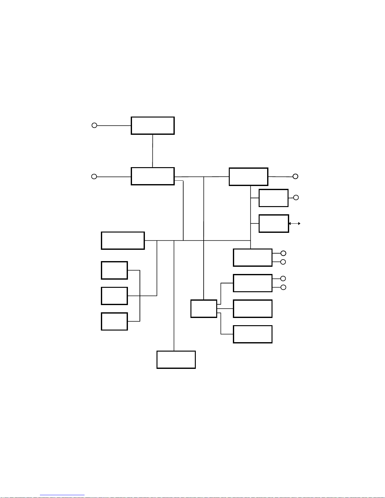
ErgoLine D330/D340
Customer Engineer Manual
Page 1-6
F
IGURE
1-1. B
LOCK DIAGRAM OF ERGOLINE
D330 & D340
Power
Supply
Line Interface
Circuit
Microprocessor
Terminal
Adapter
1
EPROM
RAM
EEPROM
Static
I/F
1
Infra-Red
I/F
1
TAPI
Audio I/O
1
Handset
Loudspeaker
Microphone
ARCOFI
Display LEDs
& Keys
T
x
R
x
IN
OUT
V.24
8V~
5V
Interchangeable
Line Interface:
- 2-wire U
PN
- 4-wire S
0
voice
(B0/B1)
data
(B1)
messages
(D)
Note 1: The Infra-Red, Static, Audio
and V.24 interfaces are not
available on the D330
Page 13
ErgoLine D330/D340
Customer Engineer Manual
Page 1-7
P
HYSICAL LAYOUT
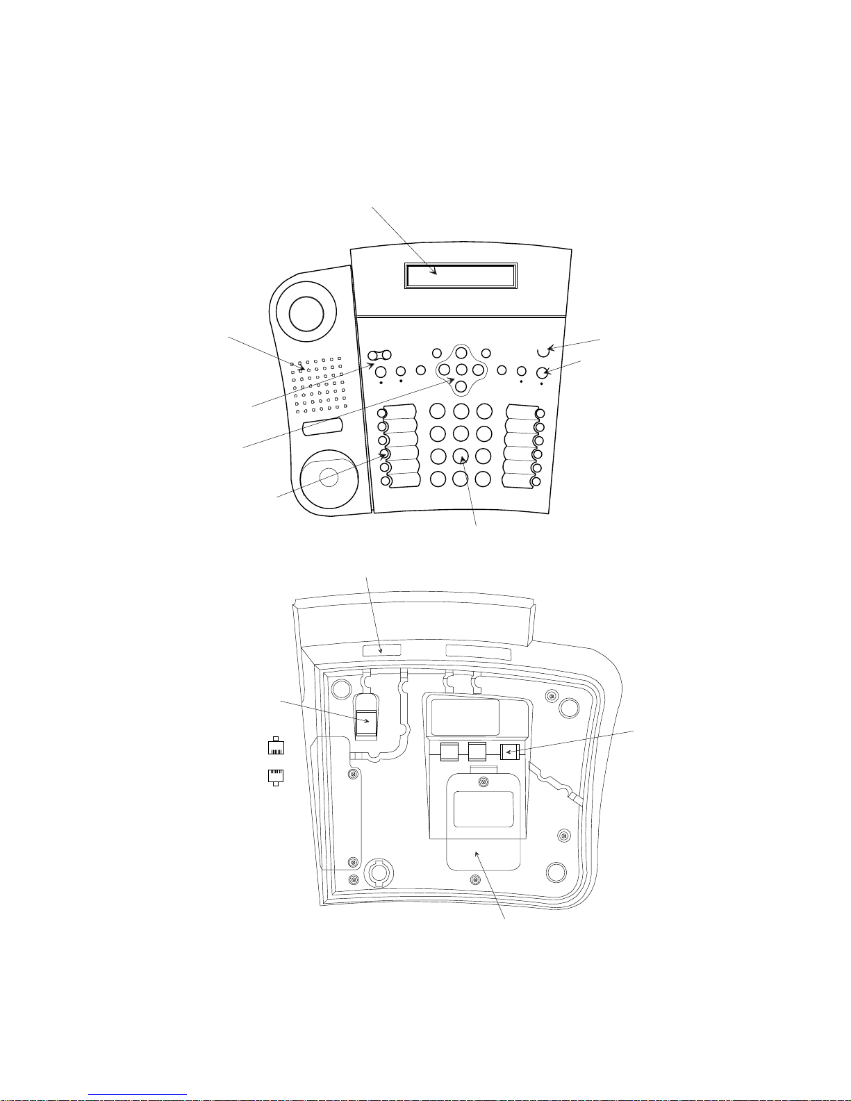
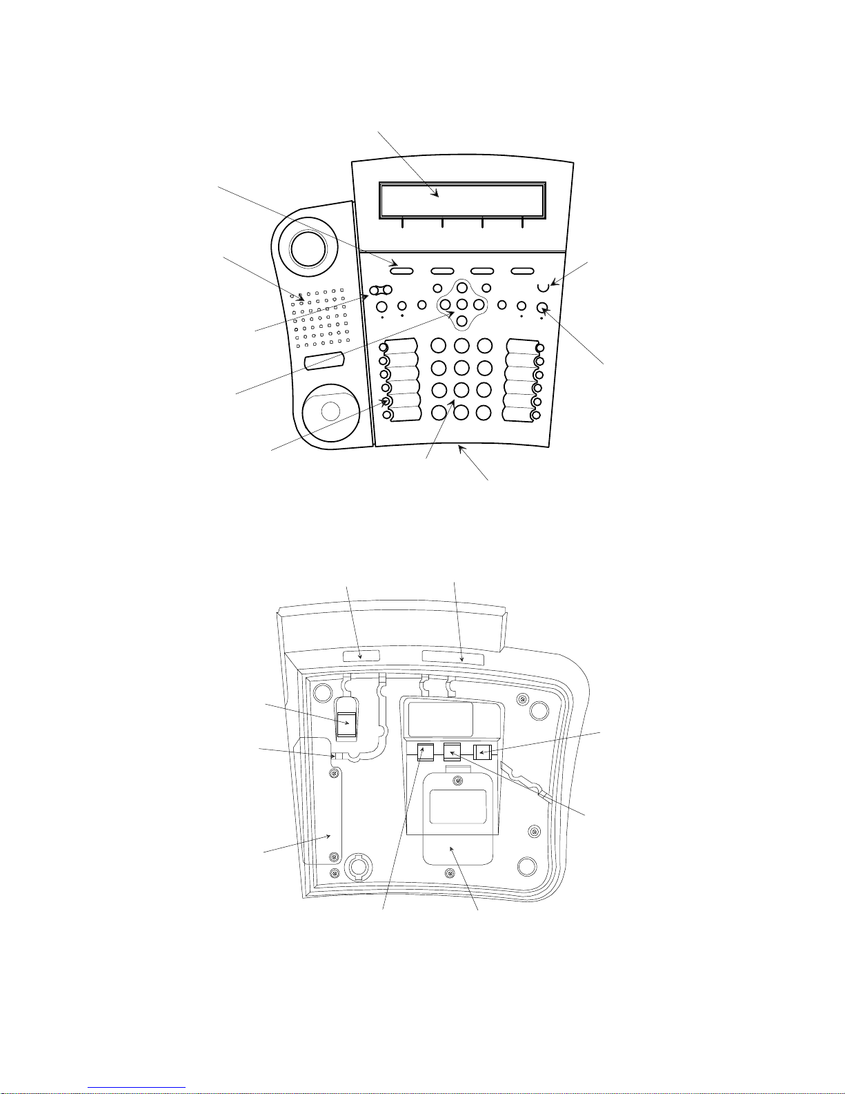
The physical parts of the ErgoLine D330 and D340 are illustrated in the following
diagrams.
2x24 Display
Loudspeaker
Volume Control
Cursor Keys
Programmable Keys
Alpha-numeric Keys
Microphone
Fixed Function Keys
F
IGURE
1- 2 T
OP VIEW OF ERGOLINE
D330.
PC Interface
Handset
cord
socket
Software
hatch
2-wire/4-wire
Line I/F
2-wire orientation
4-wire orientation
F
IGURE
1-3. B
OTTOM VIEW OF ERGOLINE
D330
Page 14
ErgoLine D330/D340
Customer Engineer Manual
Page 1-8
4x40 Display
Microphone
Soft Keys
Loudspeaker
Volume Control
Cursor Keys
Programmable Keys Alpha-numeric Keys
ASCII Keypad
Infra-red Port
Fixed Function Keys
F
IGURE
1-4. T
OP VIEW OF ERGOLINE
D340
Figure 1-5. Bottom View of Ergoline D340
PC Interface
V24 Data option
Handset
cord
socket
Audio
socket
Software
hatch
Static I/F
socket
DSS
connector
cover
2-wire/4-wire
Line I/F
Optional
power
supply
Page 15
ErgoLine D330/D340
Customer Engineer Manual
Page 1-9
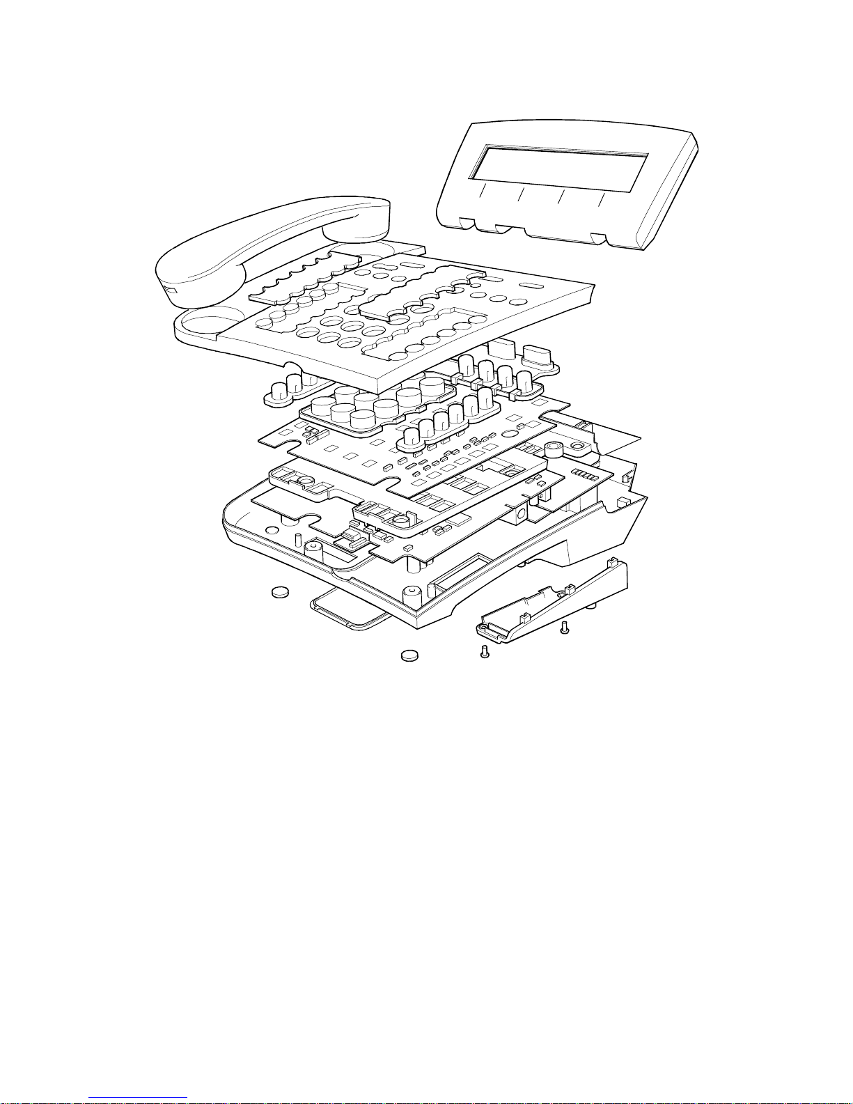
F
IGURE
1-6. E
XPLODED VIEW OF ERGOLINE TERMINAL
Page 16

ErgoLine D330/D340
Customer Engineer Manual
Page 1-10
D
ESCRIPTION OF FUNCTIONS
Numeric Keys
The Numeric Keys are used when initiating a call, invoking an exchange facility,
storing and retrieving numbers or when programming the ErgoLine.
Programmable Keys
The Programmable Keys can be used to store various PABX commands including
speed-dial and group features. Each Programmable key has an LED and a label.
Fixed Function Keys
The Fixed Function Keys are used as follows:
LOUDSPEAKER
Press this key to select and de-select
hands-free
operation, or to de-select
listen-in
and select
soft-speaking
MIC
.
Press this key to switch the
active microphone
off
and on. The LED indicates the status of the active
microphone as follows:
•
LED off: The handset microphone is on because
the handset is in use, or the set is idle
•
LED flashing: The microphone is off; the other
party cannot hear you
•
LED on: The microphone is on
REDIAL
Press this key to recall the
re-dial list
(5 numbers on
the D330, 10 numbers on the D340). The number to
be redialled can then be selected using the Cursor
Keys
EXIT
Press this key to
leave
a programming function
BACKSPACE
Press this key to
erase
the last character when
editing
HELP
(D340 only)
OPTIONS
(D330 only)
Press this key for
on-screen, context sensitive
help
Press this key to get access to the context sensitive
options which are available in the terminal.
SHIFT
Press this key to select the second level of
keypad/memory keys.
When programming, use this key to switch
between numbers and letters on the keypad.
Use this key in conjunction with the cursor keys to
change mode (data version only).
HOLD
Press this key to put a caller
on hold
or to move
between callers on hold. The Hold key is also used
when setting up a three-party conference
Cursor keys
The Cursor Keys consist of two horizontal scroll keys, indicated
< and >, and two
vertical scroll keys, indicated ∧ and ∨ , plus an OK key. The scroll keys are used to
Page 17

ErgoLine D330/D340
Customer Engineer Manual
Page 1-11
move around displayed menu items. The OK key is used to complete the
acceptance of functions when they are being invoked.
Soft Keys (D340 only)
The ErgoLine D340 has four Soft Keys. These keys are used in conjunction with
related functions displayed on the LCD.
2x24 Display (D330 only)
The ErgoLine D330 has an LCD display with 2 lines of 24 alphanumeric characters.
The display shows the following information:
•
Numbers/names dialled from the numeric keypad
•
Numbers/names dialled from a programmable key
•
Incoming call numbers/names
•
Incoming call waiting numbers/names
•
Numbers being programmed into memory
•
3 party conference members
•
Time and date
•
Cost indication for metered calls
•
Duration of metered calls
•
Call progress information
•
System information
•
Messages received (not saved in callers list)
4x40 Display (D340 only)
The ErgoLine D340 has an LCD display with 4 lines of 40 alphanumeric characters.
The display shows the following information:
•
Numbers/names dialled from the numeric keypad
•
Numbers/names dialled from a programmable key
•
Incoming call numbers/names
•
Incoming call waiting numbers/names
•
Numbers being programmed into memory
•
3 party conference members
•
Group observation display
•
Time and date
•
Cost indication for metered calls
•
Length of metered calls
•
Data being entered in via the ASCII keyboard
•
Call progress information
•
System information
•
Messages received (saved in callers list)
•
Active notice text
Page 18

ErgoLine D330/D340
Customer Engineer Manual
Page 1-12
Loudspeaker
The loudspeaker is used during hands-free operation, for ringing, for error beeps
and for group indication (softringing).
External Microphone
The External Microphone is used during hands-free operation.
2-Wire/4-Wire Line Interface - Refer to page 2-41 for installation
The ErgoLine D330 and ErgoLine D340 have modular line interfaces which allow
the line interface to be changed from a 4-wire DTX-I S
0
interface to a 2-wire DLX-U
U
PN
interface. These changes can be made in the field.
PC Interface - Refer to page 2-39 for more detail
This is used for driving the terminal via a PC allowing TAPI-compliant applications
to be used via this interface.
TAPI is the Microsoft standard for Computer-Telephony Integration (CTI). When this
option is available it is simple for a user to connect a PC to the 9-pin D-type
connector on the rear of the ErgoLine terminal. A TAPI software driver will be
provided enabling TAPI-compliant applications to be used via the interface.
A basic TAPI application introducing the user to TAPI will be included. The TAPI
driver is compatible with Windows 3.1/3.11 and Windows 95.
Handset Cord Socket
This is used to connect the handset or headset. A splitter can also be connected
which allows switching between handset and headset.
Software Hatch
Use to access the PROM sockets on the terminal motherboard.
Audio Socket (D340 only) - Refer to page 2-29 for more detail
An RJ11 socket on the base of the ErgoLine D340 can be used to connect audio
devices (e.g. a voice recorder).
Static Interface Socket (D340 only) - Refer to page 2-30 for more detail
An RJ11 socket on the base of the ErgoLine D340 can be used as an external
control line for items such as a second bell, a door opener or a door lamp. A
single input channel for foot-switch operation is also available.
Optional Power Supply (D340 only)
The ErgoLine D340 is normally line powered. If either a V.24 option or DSS(s) are
fitted, an external power supply is required. This can be fitted in the field.
Page 19

ErgoLine D330/D340
Customer Engineer Manual
Page 1-13
DSS Connector Cover (D340 only) - Refer to page 2-40 for more detail
Additional Direct Station Select (DSS) modules can be connected to an ErgoLine
D340. Each DSS module offers an additional 14 programmable keys. Up to three
DSS modules can be fitted for a total of 42 additional keys.
An external power supply is required if one or more DSS modules are fitted.
V.24 Data Option (D340 only) - Refer to page 2-31 for installation details
If data transfer is needed, a V.24 data option can be fitted. This is field installable
and requires an external power supply.
Infra Red ASCII Keyboard Port (D340 only) - Refer to page 2-42 for more detail
An infra-red ASCII keyboard is available which can be used when entering
messages or when updating the internal directory. This option is supplied as a
miniature keyboard which communicates remotely with the ErgoLine D340 via an
infra-red port on the terminal.
The ASCII keyboard has four soft keys which replicate the soft keys on the
ErgoLine D340, plus two programmable function keys. The ASCII keyboard can
communicate with the main ErgoLine terminal over one of three switch selectable
channels.
A choice of QWERTY or QWERTZ keyboard layout is available.
No installation is required, however the keyboard and D340 must be set to accept
the use of the keyboard. Operating and programming details are included with
each keyboard.
The ASCII keyboard is powered by two AAA batteries.
Page 20

ErgoLine D330/D340
Customer Engineer Manual
Page 1-14
Page 21

ErgoLine D330/D340
Customer Engineer Manual
Page 2-1
I
NSTALLATION
This section provides the information required to complete the installation of the
ErgoLine D330 and ErgoLine D340 terminals.
Unpacking
Inspect the shipping carton for any shipping damage
before
unpacking.
Unpack the contents of the box carefully, ensuring that all items are removed
before disposing of the packaging. Each box contains the following:
ErgoLine D330
•
ErgoLine D330 main terminal unit
•
Handset
•
Line cord
•
Handset cord
•
PC interface (TAPI) software diskette (3.5 inch)
•
Function key labels (blank)
•
Quick Reference Guide
ErgoLine D340
•
ErgoLine D340 main terminal unit
•
Handset
•
Line cord
•
Handset cord
•
PC interface (TAPI) software diskette (3.5 inch)
•
Function key labels (blank)
•
Quick Reference Guide
Power Supply
The ErgoLine D330 can only be line powered.
The ErgoLine D340 can be line powered or mains powered. An external power
supply, which is available as an option, is required when the following options are
fitted:
•
V.24 data option
•
DSS (Direct Station Select) modules
When an external power supply is fitted, the ErgoLine D340 automatically detects
the power source and will perform a reset operation.
The external power supply requires 220-240V AC, 50/60Hz mains power.
The ErgoLine D330 and ErgoLine D340 are equipped with an EEPROM so
programmed information is not lost if the power is removed.
Page 22

ErgoLine D330/D340
Customer Engineer Manual
Page 2-2
Cabling
Power Cord
(D340 only)
The connection of the power cord to the transformer is fixed. The other end of the
power cord terminates with a phono connector.
Pin Outs
Pin Signal
outside +
inside -
Handset Cord
The handset is connected to the ErgoLine via a four wire coiled cord which terminates with a four way male modular plug at the terminal side.
Pin Outs
Pin Signal
1 Microphone 2 Telephone
3 Telephone
4 Microphone +
Terminal Line Cord
On both ends the terminal line cord (normal length 6 m.) terminates with an eight
way plug.
Pin Outs
Pin Signal/S
0
Signal/U
PN
1 n/c n/c
2 n/c n/c
3 Transmit + n/c
4 Receive + a-wire (pos)
5 Receive - b-wire (neg)
6 Transmit - n/c
7 n/c n/c
8 n/c n/c
Note: For more information on the hardware configuration of the
corresponding boards, see the Maintenance Manual for the iS3000, Part 3
Board Interface and Strap Settings, Chapter 4.
Page 23

ErgoLine D330/D340
Customer Engineer Manual
Page 2-3
PNT1 (for use with 4-wire interface)
The ErgoLine D330 and D340 can be connected to the Switch via a Private
Network Termination (PNT1). This is an interface converter for OSI layer 1 and 2
between the echo-cancelling U interface (proprietary Philips) used on digital
subscriber lines in the SOPHO ISPBXs and the ISDN basic rate S
0
interface. At OSI
layer 3 the PNT1 is transparent.
A maximum two ErgoLine D330 terminals or two ErgoLine D340 terminals can be
connected to the PNT1.
The default TEI of the ErgoLine D330/D340 is 0. If two sets are connected to a PNT1
in a voice mode only situation, one of the sets requires the TEI to be changed to
1.
If the ErgoLine D340 is to be used in a speech and data mode, only one set can
be connected to the PNT1. The TEI in this configuration must be set to 0 and 1.
The PNT1 is equipped with two eight way modular sockets for the connection of
two S
0
ErgoLine terminals. On both jacks the corresponding pins 3, 4, 5 and 6 are
interconnected: 3 to 3, 4 to 4, etc.
When the ErgoLine terminal is line powered, power provision is done via pin 3 & 6
(positive polarity) and pin 4 & 5 (negative polarity) when the power source is in
the normal power mode.
Pin Outs
Pin Signal
1 n/c
2 n/c
3 Receive +
(power +)
4 Transmit +
(power -)
5 Transmit -
(power -)
6 Receive -
(power +)
7 n/c
8 n/c
S
0
Interface
This interface is the standard SOPHO iS3000 S
0
interface.
U
PN
interface
The ErgoLine D330 and D340 can be connected to the switch via the DLX-U U
PN
interface. This is a two wire digital interface which uses ping-pong signalling. (Do
not mistake this interface with the echo-cancelling proprietary Philips U-interface).
This interface is only capable of supporting the connection of one terminal.
When the card is projected in 1B mode, the terminal requires a TEI setting of 0.
When the card is projected in 2B mode, the terminal requires the following setting:
•
Terminal with speech service only requires the TEI setting of 0 (default)
Page 24
ErgoLine D330/D340
Customer Engineer Manual
Page 2-4
•
Terminal with Speech and Data service requires TEI setting of 0 & 1. This TEI
setting is required as the terminal has a fixed TEI of 1 for the Data service, and
requires this setting for the data service to be available.
Cable and Distances
The S0 interface consists of two balanced twisted pairs, one pair for Transmit and
one pair for Receive. The distance between the ErgoLine and the Switch depends
upon the configuration and the cable characteristics of the cable used between
the wall socket and the Main Distribution Frame (MDF).
The U
PN
interface consists of one balanced twisted pair with half duplex operation
being used. The cable length is defined by cable type.
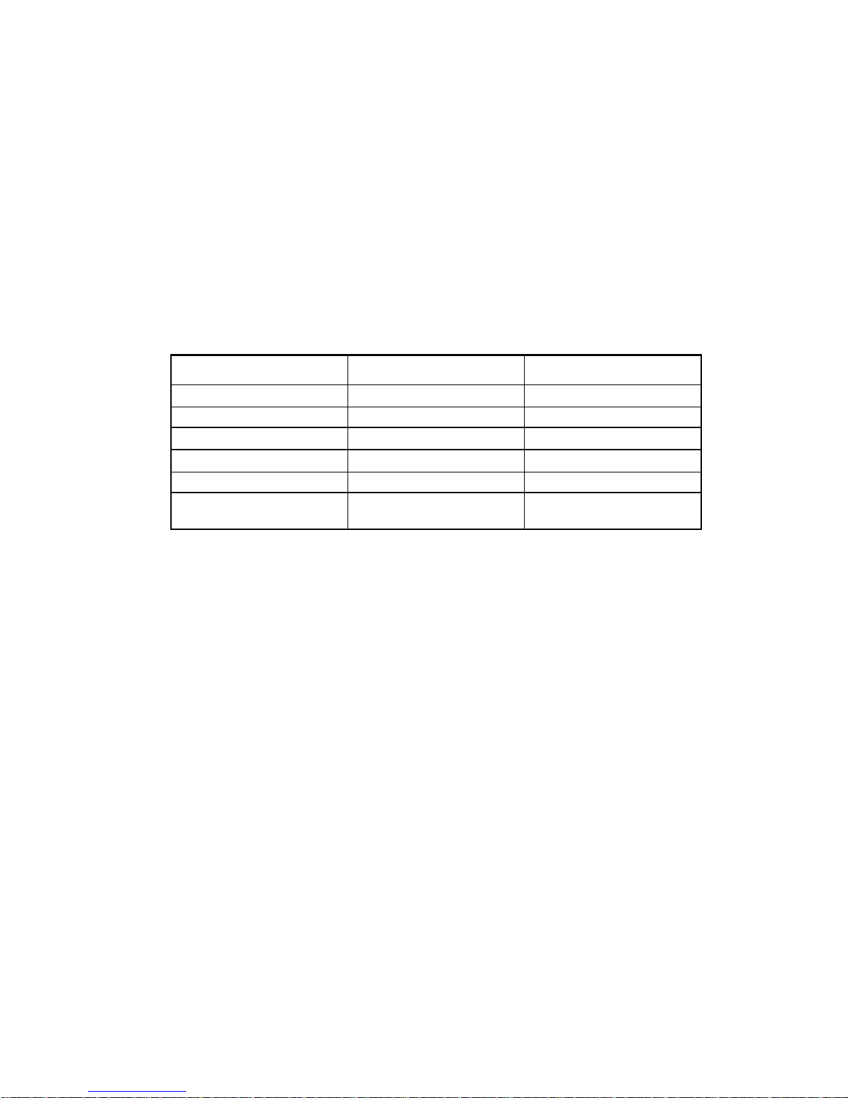
T
ABLE
2-1. T
YPICAL CABLE CHARACTERISTICS
CHARACTERISTICS
S
0
SPECIFICATION UPN SPECIFICATION
Cable impedance
100
Ω at 96kHz
100
Ω at 192kHz
Wire diameter 0.5mm 0.5mm
Loop attenuation < 10dB / km at 96kHz
≤
26dB / km at 192kHz
Round trip delay
< 1 µsec / 100m max 23 µsec (total)
ErgoLine line cord length < 10m (normally 6m) 6m
ErgoLine line cord
connector
8 pin RJ45 according to
ISO 8877
8 pin RJ45 according to
ISO 8877
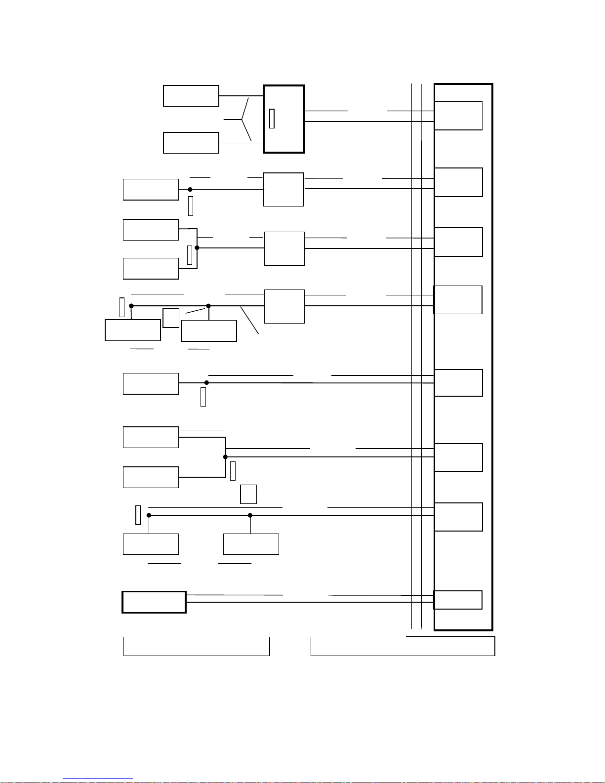
Figure 2-1 illustrates possible wiring configurations. The distances given do not
include the length of the ErgoLine terminal line cord: this length is normally 6 m.
When using another cable, the length must be <10 m.
Both twisted pairs must be terminated (preferable in the wall socket) with a 100
Ω
resistor on the location indicated in Figure 2-1.
Note 1
: When using a cable with cable characteristics different from the
ones listed in Table 2-1, the distances indicated will be different.
Note 2
: An intermediate MDF in the connection can also affect the overall
cable characteristics.
Note 3
: When cables are connected together additional attenuation,
caused by the joints, will occur.
When the ErgoLine D330 or D340 terminal is connected via a PNT1 to a DLC-U or a
DLC-C/D the distance can be extended by 1500 m. In this case the attenuation of
the cable used between the PNT1 and DLC may not exceed 15dB (at 100kHz,
without noise insertion).
Page 25
ErgoLine D330/D340
Customer Engineer Manual
Page 2-5
F
IGURE
2-1. P
OSSIBLE WIRING CONFIGURATIONS
PNT1
Direct connections using the
standard terminal line cord
1500 m
MDF
600 m
point to point
1500 m
500 m
y-config
1500 m
1500 m
600 m
100 m
(extended passive bus)
600 m
(fixed TEI)
500 m
(fixed TEI)
100 m
600 m
(fixed TEI)
DLC-C/D
DLC-U
DLC-C/D
DLC-U
DLC-C/D
DLC-U
DLC-C/D
DLC-U
DLC-I
DTX-I
ISPBX
DLC-I
DTX-I
DLC-I
DTX-I
TEI 0
TEI 1
TEI 0
TEI 0
TEI 1
TEI 0 TEI 1
TEI 0 or 0 & 1
TEI 0
TEI 1
TEI 0 TEI 1
Terminal U
PN
1000 m
TEI 0 or 0 & 1 (see note)
DLX-U
Note: DLX-U must be projected in 2B mode in order to use speech & data
because the V.24 data port has a fixed TEI of 1
100 m
Page 26
ErgoLine D330/D340
Customer Engineer Manual
Page 2-6
Connecting the D330 ErgoLine Terminal
The D330 ErgoLine terminal is connected as follows:
1. Connect the handset cord to the handset port on the underside of the
ErgoLine terminal and put the handset on the cradle.
2. Connect any other equipment to the appropriate connectors as necessary:
•
PC interface
3. Connect the telephone line cord to the line port on the underside of the
ErgoLine terminal.
4. Plug in the telephone line cord at the PNT1 or the wall socket.
When the ErgoLine terminal has been successfully connected to the following:
•
PNT1 or wall socket
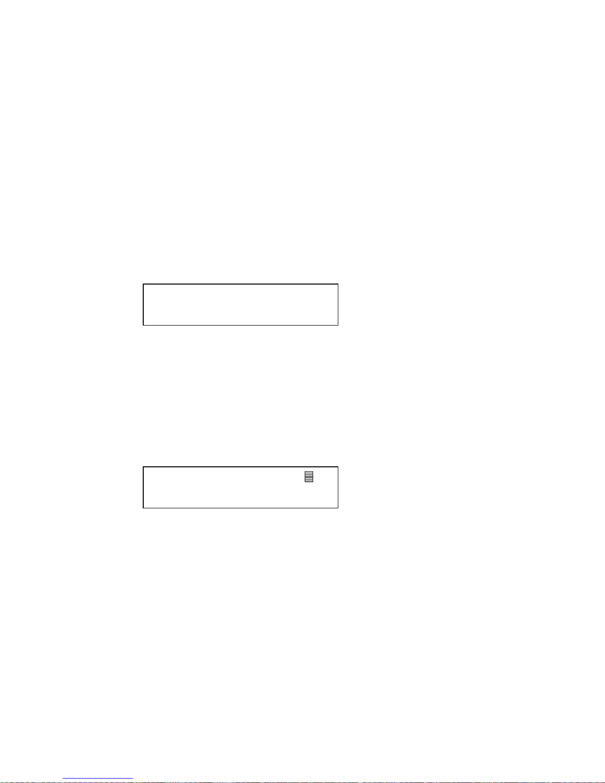
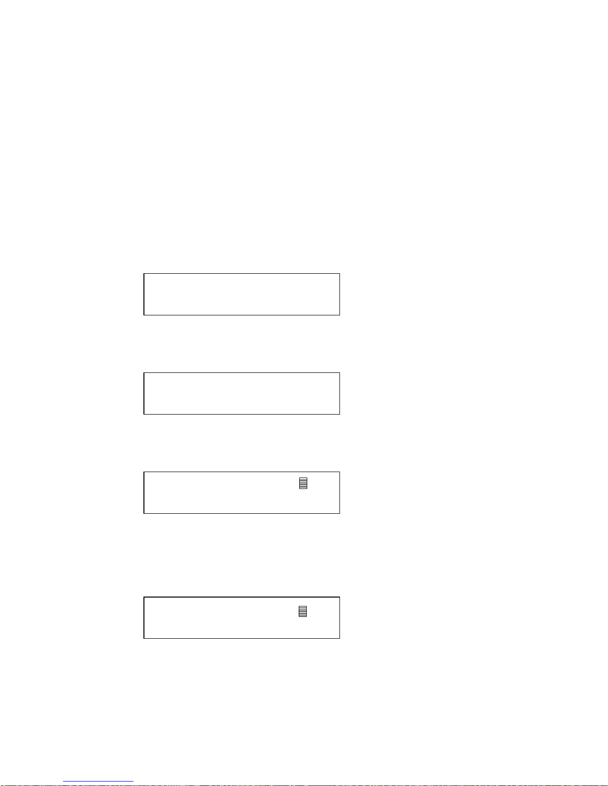
The following display will appear on the screen:
The ErgoLine terminal is now ready to receive commands from the Switch.
Programming the ErgoLine terminal is possible before download, however call set-
up is not possible during this time. The default values can be overruled by the
Switch or can be changed by the programming procedure from the ErgoLine
terminal.
When the message
Non-Operational
is removed, which can take a few
moments, dial tone will be received upon lifting the handset.
The following display will appear on the screen:
Note:
If no dial tone is received, check the status of the circuit in the Switch.
Non-Operational
27/06/96
14:33
Page 27
ErgoLine D330/D340
Customer Engineer Manual
Page 2-7
D330 Terminal Endpoint Identification (TEI)
In the specification of the terminal message protocol (TMP) a B channel is
identified by a port number. The ErgoLine terminal uses fixed TEIs for B channel
allocation.
For ErgoLine D330 terminals the TEI can have two different values:
0 = B channel 0
1 = B channel 1
When 0 or 1 is selected only one B channel is used for voice. The TEI setting should
only be changed during installation. This is done as follows:
1. Press the
Options
key then scroll down until the
Features
option is displayed
and press the
OK
key.
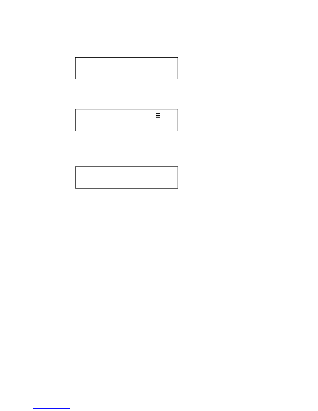
The following display will appear on the screen:
⋅
2. Scroll down until the
SetPhone
option is displayed and press the
OK
key.
The following display will appear on the screen:
3. Scroll down until the
Select mode
option is displayed and press the
OK
key.
The following display will appear on the screen:
4. Enter the service password of the set,
12687
.
Note
: This password cannot be changed. It is for the use of maintenance
personnel only
The following display will appear on the screen:
5. Press the OK key. The display will return to idle indicating that the Service Mode
is active.
[↕ Scroll, OK accept]
Togglelist? ↕
Set language? ↕
[Enter Password]
[↕ Scroll, OK accept]
[Press OK to accept]
*****
Page 28
ErgoLine D330/D340
Customer Engineer Manual
Page 2-8
6. Press Shift, Hold.
The following display will appear on the screen:
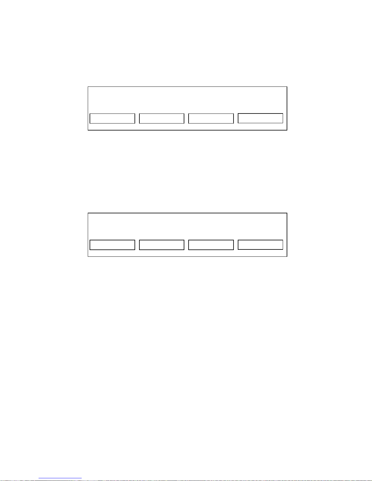
7. Scroll down until the
Set TEI
option is displayed and press OK key.
The following display will appear on the screen:
8. Enter 0 or 1 to change the TEI number, then press the OK key to accept the
new setting.
The following display will appear on the screen:
Note
: This display will be shown only for a few seconds.
Note
: The TEI must be granted by the network. If the TEI is not supported, the
display will show the message
TEI Denied
indicating that another terminal
already occupies the specified TEI i.d. The terminal TEI i.d. needs to be changed
to a unique value before it will be accepted.
If the set remains non-operational after setting the TEI, the message
TEI Denied
can be displayed by pressing the down arrow key.
Note
: If the TEI has been changed it is necessary to remove and re-insert the line
cord for the change to take effect.
Connecting the D340 ErgoLine Terminal
The D340 ErgoLine terminal is connected as follows:
1. Connect the handset cord to the handset port on the underside of the
ErgoLine terminal and put the handset on the cradle.
2. Connect the data terminal to the V.24 data port.
3. Connect any other equipment to the appropriate connectors as necessary:
•
PC interface
•
Audio interface
•
Static interface
4. Connect the mains plug transformer to the mains supply (only for mains
powered terminals). The idle menu will be on the display.
5. Connect the telephone line cord to the line port on the underside of the
ErgoLine terminal.
6. Plug in the telephone line cord at the PNT1 or the wall socket.
Clear All Keys? ↓
TEI:0
TEI Set!
[↕ Scroll, OK accept]
[Enter 0 or 1, OK]
Page 29
ErgoLine D330/D340
Customer Engineer Manual
Page 2-9
When the ErgoLine terminal has been successfully connected to the following:
•
mains supply where necessary
•
PNT1 or wall socket
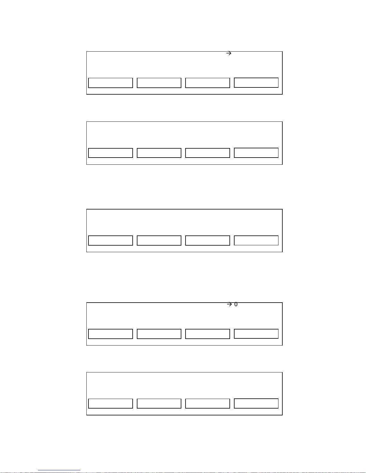
The following display will appear on the screen:
The ErgoLine terminal is now ready to receive commands from the Switch.
Programming the ErgoLine terminal is possible before download, however call set-
up is not possible during this time. The default values can be overruled by the
Switch or can be changed by the programming procedure from the ErgoLine
terminal.
When the message
Non-Operational
is removed, which can take a few
moments, dial tone will be received upon lifting the handset.
The following display will appear on the screen:
Note:
If no dial tone is received, check the status of the circuit in the Switch.
D340 Terminal Endpoint Identification (TEI)
In the specification of the terminal message protocol (TMP) a B channel is
identified by a port number. The ErgoLine terminal uses fixed TEIs for B channel
allocation.
For ErgoLine D340 terminals the TEI can have three different values:
•
0 = B channel 0
•
1 = B channel 1
•
0 & 1 = both B channels are used: 0 for voice and 1 for data (only on terminals
with the V.24 option plus external power supply fitted)
When 0 or 1 is selected only one B channel is used for voice: this means that the
V.24 data port remains non-operational and can not be used for data transfer.
The TEI setting should only be changed during installation. This is done as follows:
1. Press the
Features
and
SetPhone
(soft) keys.
Non-Operational
27/06/96
Time 13:34
Directory
Directory
Messages
Message
Features
Features
Keys
Keys
Page 30
ErgoLine D330/D340
Customer Engineer Manual
Page 2-10
The following display will appear on the screen:
2. Press the
SetMode
(soft) key.
The following display will appear on the screen:
3. Enter the service password of the set,
12687
.
Note
: This password cannot be changed. It is for the use of maintenance
personnel only
The following display will appear on the screen:
4. Press the OK key. The display will return to idle indicating that the Service Mode
is active.
5. Press Shift, Hold.
The following display will appear on the screen:
6. Press the
TEI
(soft) key.
The following display will appear on the screen:
Set phone
[
à Options]
Set phone
[Enter password]
Password:_
Set phone
[OK to accept]
Password:******_
Service menu
[
à Options]
Set terminal endpoint i.d. [OK accept]
TEI: 0
Language
Downl. Req
Change
Sounds
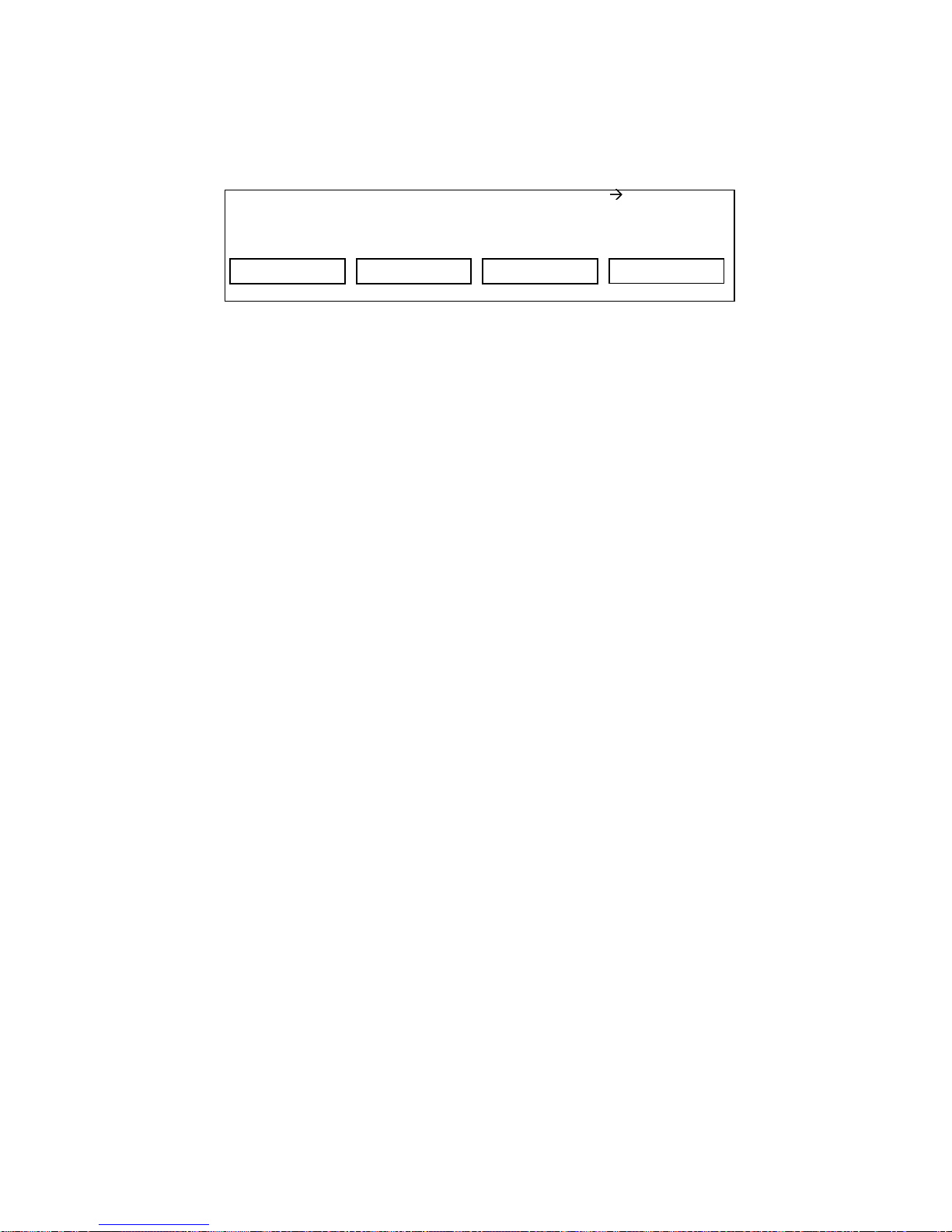
TEI
SetMode
Erase
Clean
Cancel
Cancel
Cancel
Cancel
Cancel
Page 31
ErgoLine D330/D340
Customer Engineer Manual
Page 2-11
7. Press the Change (soft) key to change the TEI number, then press the OK key
to accept the new setting.
The following display will appear on the screen:
Note
: This display will be shown only for a few seconds.
Note
: The TEI must be granted by the network. If the TEI is not supported, the
display will show the message
TEI Denied
indicating that another terminal
already occupies the specified TEI i.d. The terminal TEI i.d. needs to be
changed to a unique value before it will be accepted.
If the set remains non-operational after setting the TEI, the message
TEI
Denied
can be displayed by pressing the down arrow key.
Note
: If the TEI has been changed it is necessary to remove and re-insert the
line cord for the change to take effect.
System Requirements
The following firmware and software levels (or higher) are required to support
ErgoLine:
•
CPU package SSW805.24.d
•
DLX-U firmware 300.103
•
PPU package PMC 405.07 or PPU 162.07 or PPU 262.07
•
DTX-I firmware 203.601
Terminal endpoint i.d. set! [
à Options]
Downl. Req TEI Clean
Cancel
Page 32

ErgoLine D330/D340
Customer Engineer Manual
Page 2-12
Preparing Download Information
The following can be downloaded from the Switch to the ErgoLine:
•
V.24 port characteristics
•
Function key data
•
Facility codes and local functions
V.24 Port Characteristics
V.24 data (and function key data) can be downloaded from the Switch using
Operational Maintenance (see the chapter Maintenance and Testing)
Function Key Data
Each programmable key can be downloaded (or programmed) under 2 levels.
The keypad keys can be downloaded (or programmed) under the second level.
Both levels of a programmable key can be used to store a number for speed
dialling or for a function code.
A function code is a code that the user can program under a key (or that can be
downloaded) thus giving that key a specific function. The function is a
combination of what happens when the key is pressed and what the LED shows.
The parameter name used in OM commands for a function code is
LED_CODE
.
Note
: It is not recommended that a function code be stored under the first
level and another function code be stored under the second level. Once a
function code is stored under one level, the other level should be
programmed with a number for speed dialling. Some function codes also
require that a specific number is stored under a specific level.
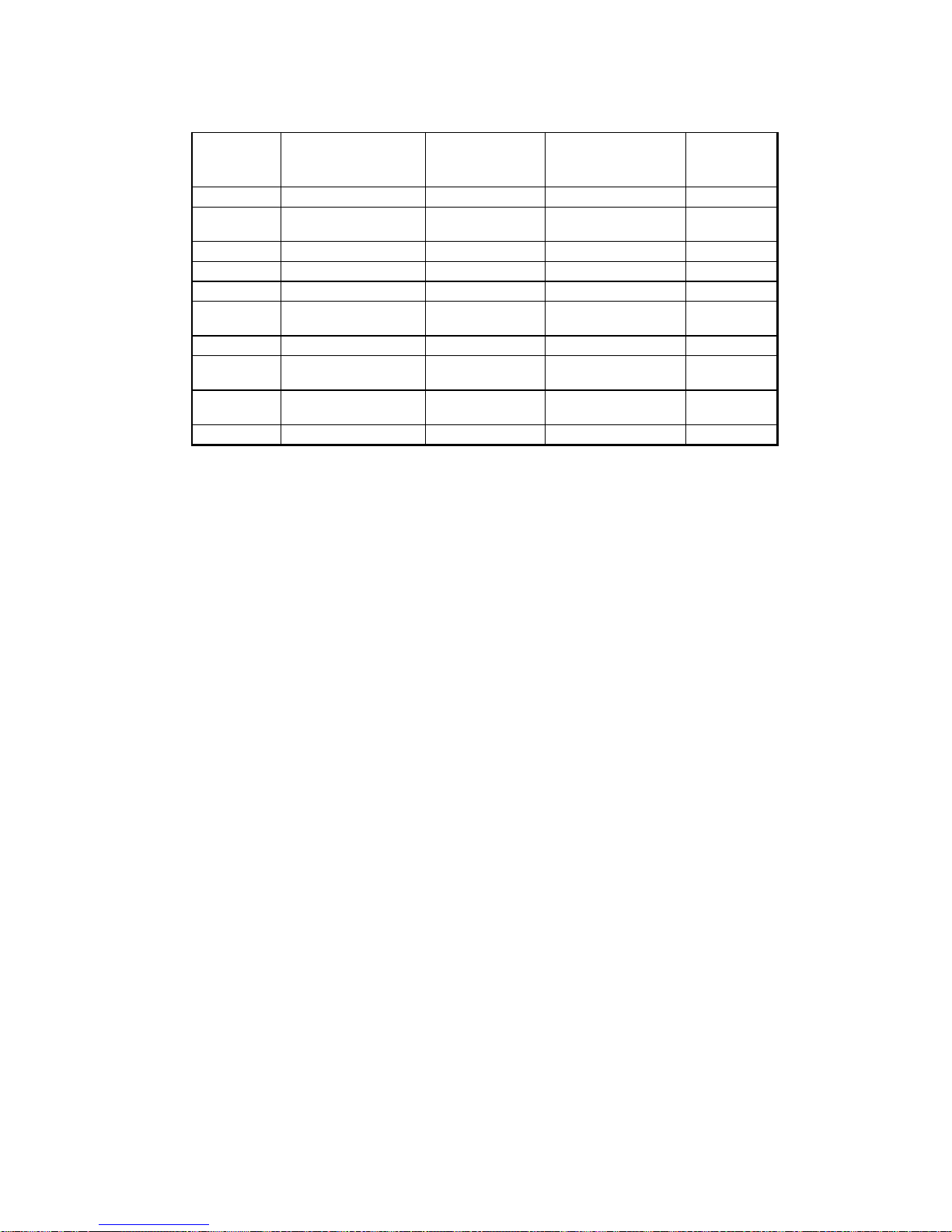
The function codes are listed in Table 2-2.
To enable the user to make use of certain functions downloaded (or
programmed) under a key, it is also necessary to download the relevant Switch
facility codes. This gives the relation between
function code
and
facility code(s)
within the ErgoLine. The translation between the function code and the facility
code which is sent to the Switch takes place in the ErgoLine. This construction
relieves the user of having to remember facility codes and makes the ErgoLine
programming independent of facility codes (i.e. function codes are always the
same whereas facility codes may differ from one Switch to the next).
Note
: It is possible to erase the EEPROM by powering the set while holding
keys *,5,3 to clear all keys/functions.
Page 33

ErgoLine D330/D340
Customer Engineer Manual
Page 2-13
Table 2-2 shows whether facility codes need to be downloaded for a specific
function. Downloading the facility codes is discussed in the following chapter.
T
ABLE
2-2. F
UNCTION CODES FOR FUNCTION KEY DOWNLOADING
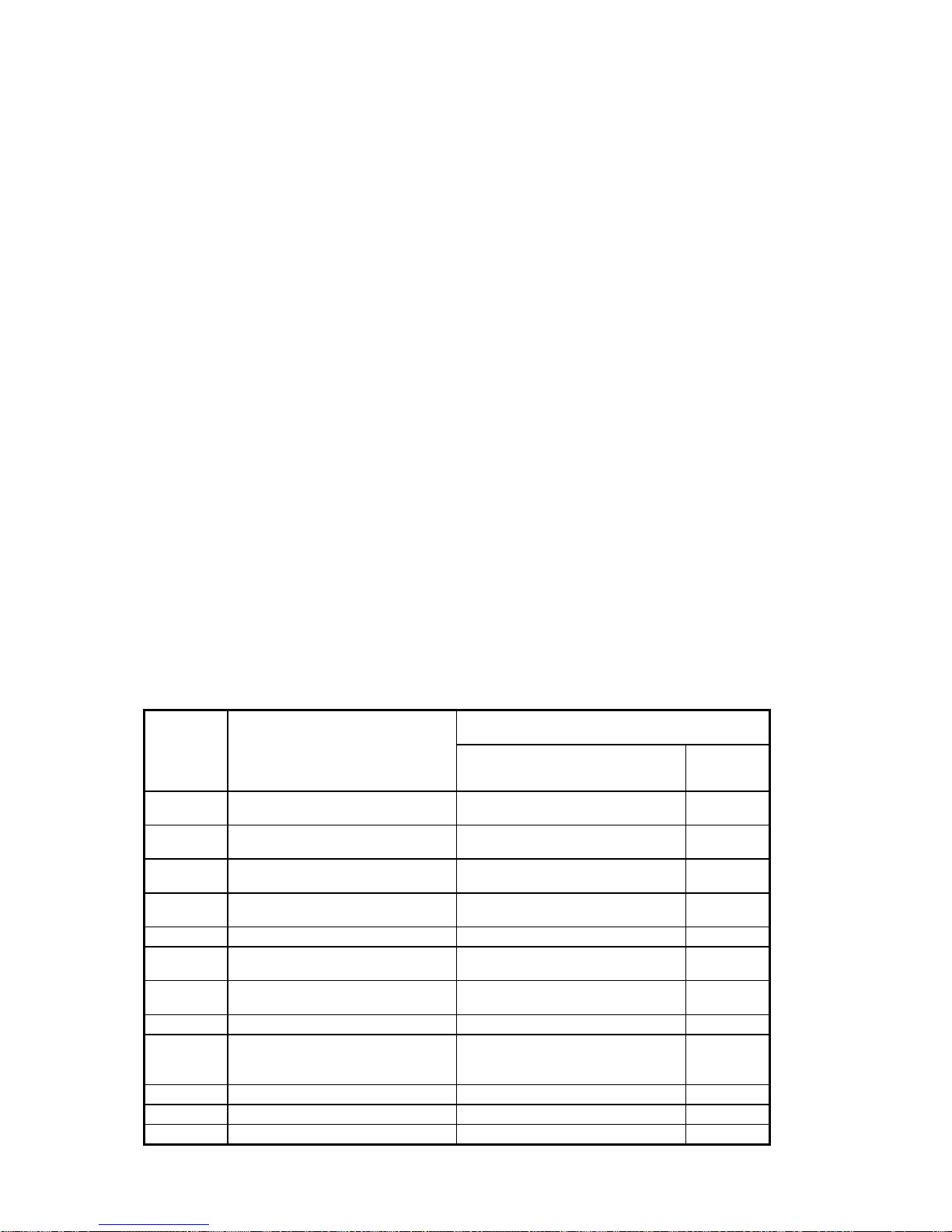
FUNCTION
CODE
FUNCTION TO BE
DOWNLOADED
NUMBER TO BE
STORED ON FIRST
LEVEL
NUMBER TO BE STORED
ON SECOND LEVEL
FACILITY
NUMBER
0 Speed dialling Speed dial
number*
Speed dial number* -
1 Follow-me key Extension DNR
(optional)
Speed dial number* 32, 33
2 Automatic ring-back
key
None Speed dial number* 30, 31
4 Diversion on busy key None Speed dial number* 51,52
5 Do-not-disturb key None Speed dial number* 28, 29
6 Night absence key None Speed dial number* 57, 58
7 Exec./sec. absence
key
None Speed dial number* 26, 27
8 Group absence key None Speed dial number* 47, 48
32 Intercom enable None Speed dial number* 33 Send tones (DTMF) None Speed dial number* 37 Switch voice/data
mode
None Speed dial number* -
38 Data call key None Speed dial number* 39 Message waiting None Speed dial number* 77, 78, 79
40 Set data default See note 1 Speed dial number*
45 Group ring (soft ring) None Speed dial number* 42
51 Call waiting indication None Speed dial number* 44
52 One keystroke set-up None Speed dial number* 40
57 Auto answer voice None Speed dial number* 38
58 Ringer None Speed dial number* 59 Status monitoring None Speed dial number* 61 General facility cancel None Speed dial number* 53
62 Show absent/present
status
None Speed dial number* -
65 Extension key Extension DNR Speed dial number* 49
66 Line Key Line number (only
monitoring)
Speed dial number* -
71 On/Off hook None Speed dial number* 73 PFM Request code
(see table 2-3)
Speed dial number* 61
74 Direct password key None Speed dial number* 65
75 Extension intercom key Extension DNR Speed dial number* 49, 67
99 Activate answerback
message (notice)
None Speed dial number* -
100 Private key Extension DNR Speed dial number* 49
101 Personal key Extension DNR Speed dial number* 49
102 Executive key Extension DNR Speed dial number* 49
103 Member key Extension DNR Speed dial number* 49
104 Group key Extension DNR Speed dial number* 49
105 Private park key Park DNR Speed dial number* 49
106 Group park key Park DNR Speed dial number* 49
107 Alternative secretary Extension DNR Speed dial number* 32, 33
Page 34
ErgoLine D330/D340
Customer Engineer Manual
Page 2-14
T
ABLE
2-2. F
UNCTION CODES FOR FUNCTION KEY DOWNLOADING
FUNCTION
CODE
FUNCTION TO BE
DOWNLOADED
NUMBER TO BE
STORED ON FIRST
LEVEL
NUMBER TO BE STORED
ON SECOND LEVEL
FACILITY
NUMBER
(optional)
110 Activate auto answer
1hr
None Speed dial number* 38
111 Footpedal None Speed dial number* 112 Second ringer None Speed dial number* 113 Busy indication None Speed dial number* 114 Manual busy
indication
None Speed dial number* -
115 Door opener None Speed dial number* 116 X-input instead of
microphone
None Speed dial number* -
117 Handset operation
without hook
None Speed dial number* -
118 Headset None Speed dial number* -
Note 1 : See V24 Data Guide for settings
Function Key Layout
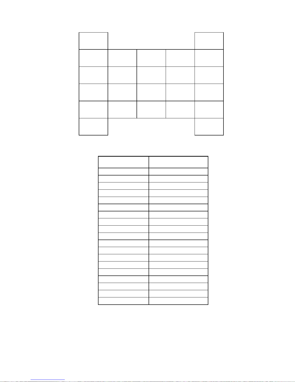
When preparing download information in the Switch, it is necessary to know the
numbering of the keys on the ErgoLine. The following diagram shows the
numbering of the keys on the main terminal, the three optional DSS’s and on the
ASCII keypad.
Note
: The format used to describe the numbering is as follows:
(Keypad keys are shifted level only)
Key
= Marking on the terminal (numbers in italics are keypad
key numbers)
Test
= Indication on LCD during the keyboard test in the
maintenance menu
SOPHO
= Function key numbering for downloading from SOPHO iS
in function key menus.
F
IGURE
2-2. E
RGOLINE MAIN TERMINAL KEY NUMBERING
Page 35
ErgoLine D330/D340
Customer Engineer Manual
Page 2-15
Key 1
Test 1/19
SOPHO 0
Key 7
Test 1/23
SOPHO 6
Key 2
Test 1/13
SOPHO 1
Key
1
Test 1/32
SOPHO 27
Key
2
Test 1/33
SOPHO 28
Key
3
Test 1/34
SOPHO 29
Key 8
Test 1/17
SOPHO 7
Key 3
Test 1/31
SOPHO 2
Key
4
Test 1/26
SOPHO 30
Key
5
Test 1/27
SOPHO 31
Key
6
Test 1/28
SOPHO 32
Key 9
Test 1/35
SOPHO 8
Key 4
Test 1/25
SOPHO 3
Key
7
Test 1/44
SOPHO 33
Key
8
Test 1/45
SOPHO 34
Key
9
Test 1/46
SOPHO 35
Key 10
Test 1/29
SOPHO 9
Key 5
Test 1/43
SOPHO 4
Key ✳
Test 1/38
SOPHO 36
Key
0
Test 1/39
SOPHO 26
Key
#
Test 1/40
SOPHO 37
Key 11
Test 1/47
SOPHO 10
Key 6
Test 1/37
SOPHO 5
Key 12
Test 1/41
SOPHO 11
Figure 2-3. ErgoLine Terminal Key Numbering : other keys
KEY DESCRIPTION TEST INDICATION
Volume - 1/0
Volume + 1/1
Softkey 1 1/2
Softkey 2 1/3
Softkey 3 1/4
Softkey 4 CANCEL (exits from test)
Loudspeaker 1/18
Last Number Redial 1/6
Mute 1/7
Exit 1/8 (also exits from test)
Cursor up 1/9
Cursor down 1/15
Cursor left 1/14
Cursor right 1/21
Backspace 1/22
Help 1/16
Shift 1/10
Hold 1/11
Hookswitch 1/48
Page 36
ErgoLine D330/D340
Customer Engineer Manual
Page 2-16
Key
= Marking on the terminal (numbers in italics are keypad
key numbers)
Test
= Indication on LCD during the keyboard test in the
maintenance menu
SOPHO
= Function key numbering for downloading from SOPHO iS
in function key menus.
F
IGURE
2-4. DSS K
EY NUMBERING
DSS 1 Keys DSS 2 Keys DSS 3 Keys
Key 1-1
Test 2/1
SOPHO 12
Key 2-1
Test 3/1
SOPHO 100
Key 3-1
Test 4/1
SOPHO 114
Key 1-2
Test 2/4
SOPHO 13
Key 2-2
Test 3/4
SOPHO 101
Key 3-2
Test 4/4
SOPHO 115
Key 1-3
Test 2/7
SOPHO 14
Key 2-3
Test 3/7
SOPHO 102
Key 3-3
Test 4/7
SOPHO 116
Key 1-4
Test 2/10
SOPHO 15
Key 2-4
Test 3/10
SOPHO 103
Key 3-4
Test 4/10
SOPHO 117
Key 1-5
Test 2/13
SOPHO 16
Key 2-5
Test 3/13
SOPHO 104
Key 3-5
Test 4/13
SOPHO 118
Key 1-6
Test 2/16
SOPHO 17
Key 2-6
Test 3/16
SOPHO 105
Key 3-6
Test 4/16
SOPHO 119
Key 1-7
Test 2/19
SOPHO 18
Key 2-7
Test 3/19
SOPHO 106
Key 3-7
Test 4/19
SOPHO 120
Key 1-8
Test 2/22
SOPHO 19
Key 2-8
Test 3/22
SOPHO 107
Key 3-8
Test 4/22
SOPHO 121
Key 1-9
Test 2/0
SOPHO 20
Key 2-9
Test 3/0
SOPHO 108
Key 3-9
Test 4/0
SOPHO 122
Key 1-10
Test 2/3
SOPHO 21
Key 2-10
Test 3/3
SOPHO 109
Key 3-10
Test 4/3
SOPHO 123
Key 1-11
Test 2/6
SOPHO 22
Key 2-11
Test 3/6
SOPHO 110
Key 3-11
Test 4/6
SOPHO 124
Key 1-12
Test 2/9
SOPHO 23
Key 2-12
Test 3/9
SOPHO 111
Key 3-12
Test 4/9
SOPHO 125
Key 1-13
Test 2/12
SOPHO 24
Key 2-13
Test 3/12
SOPHO 112
Key 3-13
Test 4/12
SOPHO 126
Key 1-14
Test 2/15
SOPHO 25
Key 2-14
Test 3/15
SOPHO 113
Key 3-14
Test 4/15
SOPHO 127
Note
: Keys at the DSS 2 and DSS 3 are not downloadable in the CPU package
SSW 805.
Page 37
ErgoLine D330/D340
Customer Engineer Manual
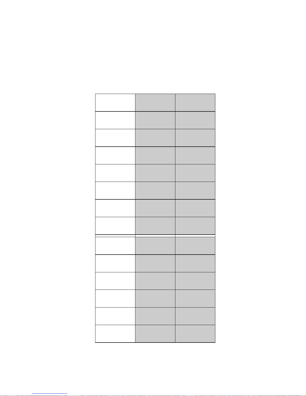
All of the keys shown in Figures 2-2 and 2-4 are programmable. The downloadable
keys are shown in the non-shaded boxes. The function keys on the main terminal and
the DSS 1 keys are programmable on both levels. The numeric keys on the main
terminal are programmable on the second level only. The keys shown in the shaded
boxes (DSS 2 & DSS 3) are not downloadable in SSW 805 but are programmable on
both levels.
Facility Codes and Local Functions
To give the user full access to ISPBX and ErgoLine D330 and D340 facilities, it is
necessary to download facility codes. These facility codes are used for translation when a
function key has been programmed. Some codes need to be downloaded to allow
facilities to be presented in soft-key menus (for example, the automatic ring-back soft-key
is only presented when appropriate and when the automatic ring-back code has been
downloaded). It may also be required to download information to enable or disable certain
local ErgoLine terminal functions.
For the purposes of facility code and local function downloading, the same Operational
Maintenance commands are used as for function key downloading. This means that the
information to be downloaded is entered as if it were to be downloaded to function keys.
Information is downloaded to 'facility numbers' instead of 'function keys'. The facility
numbers have nothing to do with the actual keys and can be considered to be an 'address'
in the ErgoLine terminal memory. Facility codes are always downloaded to key level 0.
Table 2-3 provides a list of functions that can be downloaded and the Facility Number to
which the information is written in the ErgoLine terminal. Since the names used for
particular facility codes differ in various ISPBXs, their unique identity is given in the
column Result ID used when defining facility codes.
Local ErgoLine terminal functions are enabled or disabled by downloading a 0 or a 1. The
parameter name used in OM commands for the facility number is KEY.
Note: For a number of functions it is also necessary that the user has the correct
facility class marks assigned in the SOPHO-iS. If no facility class mark is assigned
the user cannot use the facility.
TABLE 2-3. FACILITY CODES AND ADDRESSES FOR FACILITY CODE DOWNLOADING
INFORMATION TO BE STORED
FACILITY
NUMBER
NUMBER/FACILITY CODE RESULT
26
Executive/secretary absence Executive/secretary absent
27
28
Do-not-disturb Activate do-not-disturb
29
30
Automatic ring-back Activate automatic ring-back
31
32
Follow-me Activate follow-me
33
FUNCTION
DOWNLOADED
Executive/secretary present
Cancel do-not-disturb
cancel automatic ring-back
Cancel follow-me
34 Prepare Prepare follow-me 28
35 Activate from dest Activate follow-me from
destination
36 Deactivate from dest Deactivate follow-me from
destination
37 Cancel
38 Auto answer 0 = No,
1 = Continuous
2 = 1hour
39 Microphone blocked enable 0 = No, 1 = Yes L
40 One keystroke set-up 0 = No, 1 = Yes L
41 Add-on Activate 3-party call 55
ID
40
41
66
67
56
57
27
32
29
30
L
Page 2-17
Page 38
ErgoLine D330/D340
Customer Engineer Manual
Page 2-18
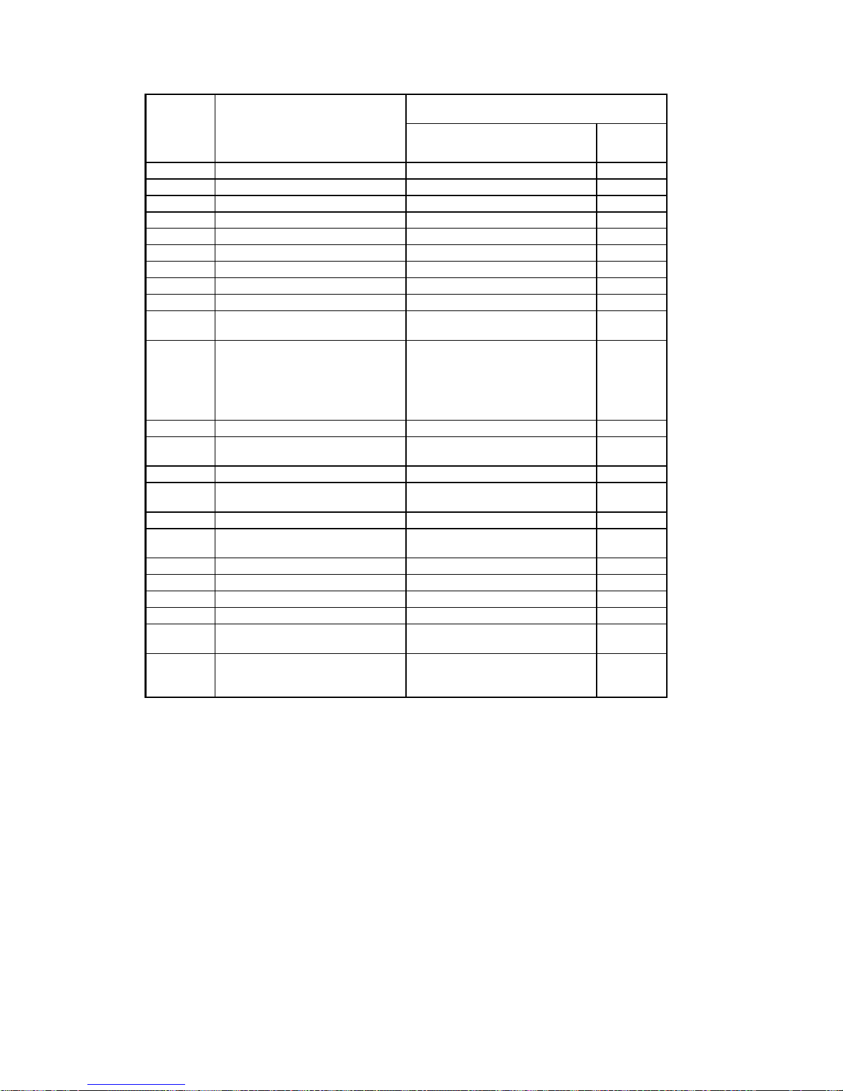
INFORMATION TO BE STORED
NUMBER/FACILITY CODE RESULT ID
2 = 1hour
39 Microphone blocked enable 0 = No, 1 = Yes L
40 One keystroke set-up 0 = No, 1 = Yes L
41 Add-on Activate 3-party call 55
42 Group ring 0 = No, 1 = Yes L
43 Keyclick (ASCII) 0 = No, 1 = Yes L
44 Call waiting indication 0 = No, 1 = Yes L
45 Time and date update 0 = No, 1 = Yes X
46 Return to dialtone 0 = No, 1 = Yes X
47
48
Group absence Switch out group by member
Switch in group by member
35
36
49
(see
Download
Examples
page
2-26)
Group member key; Extension
key; Executive key; Private
key; Park key; Personal key
Selective call pick-up 34
50 Call waiting pick-up Call waiting pick-up 75
51
52
Diversion on busy Activate diversion on busy
Cancel diversion on busy
98
99
53 General facility cancel General cancel 103
57
58
Night absence Night extension absent
Night extension present
44
45
59 End dial suffix End dial suffix x
61 Peripheral Facility Manager
(PFM)
PFM prefix 82
62 Camp-on-busy (WAIT) Camp-on-busy 102
63 Break-in (INTRUDE) Break-in 58
65 Direct password Direct password dialling 109
67 Extension intercom Intercom 69
70
Executive/secretary absence Executive/secretary absent
Executive/secretary present
40
41
77
78
79
Message Waiting Destination Type 0: LED is on
Type 1: LED is winking
Type 2: LED is flashing
*)
*)
*)
x = supported
- = not supported
L = local
*) The DNR to access the device which causes the message waiting e.g. the DNR of the
Voice Mail system.
FUNCTION
DOWNLOADED
FACILITY
NUMBER
Page 39

ErgoLine D330/D340
Customer Engineer Manual
Page 2-19
System Preconditions
Facility class mark 12 must always be assigned to the ErgoLine terminal.
Depending on the facilities required, other facility class marks must also be
assigned to the ErgoLine terminal. For example, if the extension user wants to use
the do-not-disturb facility, the facility class mark
Dial Do-not-disturb
must also be
assigned.
For some facilities to function correctly it is also necessary that the ISPBX supports
a particular Terminal Message Protocol (TMP). This is the protocol used between
the ErgoLine terminal and the ISPBX in the D channel.
Extra messages offering more functionality to the user are only possible when the
ISPBX supports certain TMP modes:
- X mode for explicit knowledge of the call state;
- D mode : for enhanced display messages;
- U mode : for user to user messages;
- K mode : for specific key system messages.
The following pages contain a list of functions with their function codes and the
Conditions required to allocate the function to a user.
N
O FUNCTION
(
FUNCTION CODE
0)
F
OLLOW-ME (DIVERSION
)(
FUNCTION CODE
1)
Extension is
Follow-me entitled
facility class mark 07.
Facility codes for:
•
activate follow-me from primary (facility number 32)
•
deactivate follow-me from primary (facility number 33)
•
prepare follow-me from primary (facility number 34)
•
activate follow-me from destination (facility number 35)
•
deactivate follow-me from destination (facility number 36)
have to be downloaded.
A
UTOMATIC RING-BACK (CALL BACK
)(
FUNCTION CODE
2)
Facility codes for activate (facility number 30) and cancel (facility number
31) automatic ring-back have to be downloaded.
D
IVERSION ON BUSY
(
FUNCTION CODE
4)
Extension is set to
Diversion on busy
to another extension; this facility is also
known as Call forwarding on busy: facility class mark 37.
Facility codes for activate (facility number 51) and cancel (facility number
52) diversion on busy have to be downloaded.
Page 40

ErgoLine D330/D340
Customer Engineer Manual
Page 2-20
DO-
NOT-DISTURB
(
FUNCTION CODE
5)
Extension is
Do-not-disturb
entitled: facility class mark 25.
Facility codes for activate (facility number 28) and cancel (facility number
29) do-not-disturb have to be downloaded.
N
IGHT ABSENCE
(
FUNCTION CODE
6)
Extension is either:
•
Main Common Night Extension
•
Sub Common Night Extension
•
Individual Night Extension
•
Permanent Line Extension
•
Overflow Extension
Note
: These extension types are assigned by OM commands.
Facility codes for night extension absent (facility number 57) and night
extension present (facility number 58) have to be downloaded.
E
XECUTIVE/SECRETARY ABSENCE(FUNCTION CODE
7)
Extension is a member of an executive/secretary combination.
Facility codes for executive/secretary absent (facility number 26) and
executive secretary present (facility number 27) have to be downloaded,
when programmed without directory number.
G
ROUP ABSENCE
(
FUNCTION CODE
8)
Extension is a member of a group.
Facility codes for group member absent (facility number 47) and group
member present (facility number 48) have to be downloaded.
I
NTERCOM ENABLE YES/NO
(
FUNCTION CODE
32)
Default setting is
intercom enable on
(yes).
No preconditions.
S
END TONES
(DTMF) (
FUNCTION CODE
33)
No preconditions.
S
WITCH MODE (VOICE/DATA
)(
FUNCTION CODE
37)
Only for an ErgoLine terminal with a data interface.
Page 41

ErgoLine D330/D340
Customer Engineer Manual
Page 2-21
M
ESSAGE WAITING
(
FUNCTION CODE
39)
Messages are sent by the exchange.
A key must be programmed on the set for Message Waiting LED.
The LED can be programmed for a type 0, 1, or 2 message, meaning
respectively : LED on, winking or flashing.
The kind of message programmed for the different types, is system
dependent.
G
ROUP RING YES/NO (SOFT RING)(FUNCTION CODE
45)
Default setting is
group ring on
(yes).
Local function code for group ring yes/no (facility number 42) may be
downloaded; the default setting is then overruled.
Extension user can not change the setting any more if downloading was
done with priority level 3.
C
ALL WAITING INDICATION YES/NO(FUNCTION CODE
51)
Default setting is
call waiting indication off
(no).
Local function code for call waiting beep yes/no (facility number 44) may
be downloaded; the default setting is then overruled.
Extension user can not change the setting any more if downloading was
done with priority level 3.
Note
: When the switch facility class mark 34 is set, the switch delivers a call
waiting tone. When the switch facility class mark 35 is set, the switch will only
deliver a tone for call waiting from an operator. When facility class mark 34
is set and call waiting indication as also set locally, call waiting is signalled
by the switch and by the set.
A
UTO ANSWER OFF/ON
(
FUNCTION CODE
57)
Default setting is
auto answer voice off
.
Local function code for auto answer (facility number 38) may be downloaded; the default setting is then overruled.
Extension user can not change the setting any more if downloading was
done with priority level 3.
R
INGER ON/OFF
(
FUNCTION CODE
58)
Default setting is
ringer on
.
Locally programmed in toggle list and can be programmed under a key.
S
TATUS MONITORING ON/OFF
(
FUNCTION CODE
59)
Default setting is
monitoring on
.
Locally programmed in toggle list and can be programmed under a key.
Page 42

ErgoLine D330/D340
Customer Engineer Manual
Page 2-22
G
ENERAL FACILITY CANCEL
(
FUNCTION CODE
61)
Facility code for 'general facility cancel' (facility number 53) has to be
downloaded.
S
HOW ABSENT/PRESENT STATUS
(
FUNCTION CODE
62)
ISPBX must provide the absent/present status of executives and secretaries.
Extension is a member of an executive/secretary combination and a display
group.
E
XTENSION KEY
(
FUNCTION CODE
65)
Facility code for call pick-up (facility number 49) has to be downloaded.
Group arrangement has the pick-up property.
ON/
OFF HOOK
(
FUNCTION CODE
71)
The headset operation or the handset without hook mode must be
enabled, which disables the physical On/Off hook switch. The Off hook
situation is indicated by the LED (only in ‘Headset’ or ‘Headset without
hookswitch’ mode).
Programmed locally under a key.
PFM (
FUNCTION CODE
73)
A SOPHO System Manager system with the Peripheral Facility Manager
(PFM) application must be available.
Facility code to start a service call (facility number 61) must be
downloaded.
D
IRECT PASSWORD
(
FUNCTION CODE
74)
A password has to be defined.
Extension has access to password protected facilities
Facility code for direct password dialling (facility number 65) must be
downloaded.
E
XTENSION INTERCOM KEY
(
FUNCTION CODE
75)
Facility code for call pick-up has to be downloaded.
Facility code for intercom prefix must be downloaded.
Group arrangement has the pick-up property.
N
OTICE MESSAGE
(
FUNCTION CODE
99)
Extension must operate in the U mode.
The notice message must be prepared.
Page 43

ErgoLine D330/D340
Customer Engineer Manual
Page 2-23
P
RIVATE KEY
(
FUNCTION CODE
100)
Facility code for call pick-up (facility number 49) has to be downloaded.
Group arrangement has the pick-up property.
P
ERSONAL KEY
(
FUNCTION CODE
101)
Facility code for call pick-up (facility number 49) has to be downloaded.
Group arrangement has the pick-up property.
Extension must operate in X- and D- mode.
E
XECUTIVE KEY
(
FUNCTION CODE
102)
Facility code for call pick-up (facility number 49) has to be downloaded.
Group arrangement has the pick-up property.
Extension must operate in X- and D- mode.
Owner of executive line must be switched absent or busy.
M
EMBER KEY
(
FUNCTION CODE
103)
Facility code for call pick-up (facility number 49) has to be downloaded.
Group arrangement has the pick-up property.
G
ROUPKEY
(
FUNCTION CODE
104)
Facility code for call pick-up (facility number 49) has to be downloaded.
Group arrangement has the pick-up property.
P
RIVATE PARK
(
FUNCTION CODE
105)
Facility code for call pick-up (facility number 49) has to be downloaded.
Group arrangement has the pick-up property.
Park position must be defined for (group) DNR.
G
ROUP PARK
(
FUNCTION CODE
106)
Facility code for call pick-up (facility number 49) has to be downloaded.
Group arrangement has the pick-up property.
Park position must be defined for (group) DNR.
A
LTERNATIVE SECRETARY
(
FUNCTION CODE
107)
Facility codes for activate (facility number 32), cancel (facility number 33)
and follow-me primary (facility number 34) must be downloaded.
User must have follow-me entitled (ASFACM 7)
A
UTO ANSWER FOR
1 H
OUR OFF/ON
(
FUNCTION CODE
110)
Default setting is
auto answer for 1 hour off
.
Local function code for
auto answer for 1 hr
(facility number 38) may be
downloaded; the default setting is then overruled.
Extension user can not change the setting any more if downloading was
done with priority level 3.
Page 44

ErgoLine D330/D340
Customer Engineer Manual
Page 2-24
F
OOTPEDAL
(
FUNCTION CODE
111)
Can only be switched on and off when the terminal is idle.
Function can be activated via the toggle list or through a function code.
S
ECOND RINGER
(
FUNCTION CODE
112)
Can only be switched on and off when the terminal is idle.
Function can be activated via the toggle list or through a function code.
B
USY INDICATION
(
FUNCTION CODE
113)
Can only be switched on and off when the terminal is idle.
Function can be activated via the toggle list or through a function code.
M
ANUAL BUSY INDICATION
(
FUNCTION CODE
114)
Can only be switched on and off when the terminal is idle.
Function can be activated via the toggle list or through a function code.
D
OOR OPENER
(
FUNCTION CODE
115)
Function can be only be activated via a function code.
X-
INPUT INSTEAD OF MICROPHONE(FUNCTION CODE
116)
Digital equipment which support the X-protocol can be enabled/disabled
in the idle and busy condition. This can be done via the toggle list or via a
function code.
H
ANDSET WITHOUT HOOKSWITCH
(
FUNCTION CODE
117)
Allows the use of the handset with the hookswitch disabled. A function key
with ‘hookswitch’ functionality has to be programmed, or a ‘footpedal’ has
to be connected to allow correct operation of the function.
Can be activated via the menu or via a function key. The operation mode
will be displayed when the terminal is idle.
H
EADSET
(
FUNCTION CODE
118)
The hookswitch is disabled when this operation mode is active. A function
key with ‘hookswitch’ functionality has to be programmed, or a ‘footpedal’
has to be connected to allow correct operation of the function.
Can be activated via the menu or via a function key. The operation mode
will be displayed when the terminal is idle.
K
EYCLICK YES/NO
(
NO FUNCTION CODE
)
The Keyclick is only available for the ASCII keyboard. The function is only
available via the menu.
Default setting is
keyclick off
(no).
Page 45

ErgoLine D330/D340
Customer Engineer Manual
Page 2-25
O
NE KEYSTROKE SET-UP YES/NO
(
NO FUNCTION CODE
)
Default setting is
one keystroke set-up off
(no).
Local function code for one keystroke set-up yes/no (facility number 40)
may be downloaded: the default setting is then overruled.
Extension user can not change the setting any more if downloading was
done with priority level 3.
Can be locally programmed in toggle list.
C
ALL WAITING PICK-UP
(
NO FUNCTION CODE
)
Facility code for
call waiting pick-up
(facility number 50) must be
downloaded.
Facility available via softkey menu.
C
AMP-ON-BUSY (WAIT
)(
NO FUNCTION CODE
)
Extension is
Dial COB entitled
: facility class mark 36.
Facility code for camp-on-busy (facility number 62) has to be downloaded.
Facility available via softkey menu.
B
REAK-IN (INTRUDE
)(
NO FUNCTION CODE
)
Extension is
Break-in entitled
: facility class mark 02.
Facility code for break-in (facility number 63) has to be downloaded.
Facility available via softkey menu.
M
ICROPHONE BLOCK ENABLE (MICROPHONE FOR INTERCOM
) YES/NO(
NO FUNCTION CODE
)
Default setting is
Microphone for intercom off
(no).
Local function code for Microphone for intercom yes/no (facility number
39) may be downloaded; the default setting is then overruled.
Extension user can not change the setting any more if downloading was
done with priority level 3.
Can be changed via the toggle list in the features menu.
Page 46

ErgoLine D330/D340
Customer Engineer Manual
Page 2-26
Downloading Examples
Note
: When the set is delivered from the factory the EEPROM is blank i.e. all
settings are at default. When the set is connected to a PABX the set is
automatically downloaded by the PABX. The set must then be downloaded from
the PABX using the maintenance command or the download mechanism in the
set in order to change its current settings.
Local functions such as ‘One keystroke call setup’, if previously downloaded on a
facility code, must also be accounted for in the function key menu downloaded.
Preparing downloading information makes use of the following commands.
CHFKDA: <MENU>, <KEY>, <KEY-LEVEL>, [[<KEY-DATA>] ,<PRIO-CODE>
[,<LED-CODE>]];
1. In this example we will assume that you wish to download two numbers for
speed dialling to an ErgoLine D330/D340 user. Assume that you wish to store
the number
0931945880635
under the first level of key 13 and the number
0931867990214
under the second level. Assume also that the user wishes to be
able to over-write the number on the first level but not the number on the
second level. The ErgoLine terminal is in function key menu (user group) 2.
Preparing the download information for speed dialling is done by executing
the following two OM commands:
CHFKDA: 2,13,0,0931945880635,1;
CHFKDA: 2,13,1,0931867990214,3;
2. In this example we will assume that you wish allocate the follow-me facility to
an ErgoLine D330/D340 user.
Look in Table 4 for the facility codes and facility numbers required for followme. These are
activate follow-me
(facility number 32) and
cancel follow-me
(facility number 33).
Assume that the facility code to
activate
Follow me is *21 and the code to
de-
activate
Follow me is #21. Assume also that the ErgoLine terminal is in function
key menu (user group) 2.
Preparing the download information of the Follow-me facility is done by
executing the following two OM commands:
CHFKDA: 2,32,0,*21,3;
CHFKDA: 2,33,0,#21,3;
The activate FM code has the analysis result (result-ID) 27 and the cancel FM
code has the analysis result (result-ID) 32 , see Table 2-4. These commands
both use key level 0 and priority code 3. In addition, the codes for
prepare
Follow-me and
activate/deactivate
Follow-me-from-another-extension have
to be allocated.
The user will now be able to program a key for the follow-me facility.
Alternately the user may wish you to download the follow-me facility under a
specific key. The description below explains this.
Page 47

ErgoLine D330/D340
Customer Engineer Manual
Page 2-27
3. Let us now assume that you now wish to download the follow-me facility
under a specific key. Look in Table 3 for the function code required for followme, which
is 1. Notice also that there is no number to be stored on the first level of the
key and the second level of the key can be used for speed dialling.
If you now assume that the user wishes to use function key 12 for follow-me
and does not want to be able to over-write it (i.e. priority code 3). Assume
also that function key menu 2 is allocated to this ErgoLine D330/D340.
Preparing the download information of the Follow-me facility is done by
executing the following OM command:
CHFKDA: 2,12,0,,3,1;
The follow-me facility will now be available under key 12. You must have also
downloaded the facility codes as described in paragraph 2 for the facility to
work correctly.
4. Finally, let us assume that you wish to fix the
group ring
facility to
yes
, such that
it cannot be over-written by the user. Look in Table 2-4 for the facility number
required for group ring. This is facility number 42.
You will also see in the column
number/facility code
that to fix the facility to
yes
you must download the number 1 (as the KEY-DATA or FACILITY-CODE
parameter).
Assume also that function key menu 2 is allocated to this ErgoLine D330/D340.
Preparing the download information of the group ring facility is done by
executing the following OM command:
CHFKDA: 2,42,0,1,3;
The
group ring facility
will now be fixed as
yes
.
Page 48

ErgoLine D330/D340
Customer Engineer Manual
Page 2-28
Using the download facility, the following example sh ows a group with a number
of group facilities, line p osition, park position (group and private) and ca ll pickup.
DIGRPA:12096;
prop group displ superv park ext-pr membersw-all rank LP PP
9 12096 0 - yes 0000000 12050 1 0 yes yes
12051 1 1 yes yes
DIMDNR:12050;
DNR MENU
12050 8
12051 10
DIFKDA:8;
menu key level key-
data
prio-code led-code soft-ring
800- 1 9 3 (LP)
810- 1 10 8 2 0 ++7 1 1 (Group park)
8 3 0 +1 1 1 (PP)
DIFKDA:10;
menu key level key-
data
prio-code led-code soft-ring
10 0 0 - 1 9 3 (LP)
10 1 0 - 1 10 10 2 0 ++7 1 1 Group park)
10 3 0 +1 1 1 (PP) (
Note that the LED-codes represent the “group member rank”. See under <LED-
code> in appendix 2 of the OM commands manual.
DITFKM:12050;
dnr-bspt menu key lev key-
data
pr-code led-code soft-ring xlated
12050-95 8 0 0 12050# 1 65 3 YES (LP)
12050-95 8 1 0 12051 1 65 - YES (CALL-PICKUP)
12050-95 8 2 0 120967 1 65 1 YES (Group Park)
12050-95 8 3 0 120501 1 65 1 YES (PP)
DITFKM:12051;
dnr-bspt menu key lev key-
data
pr-code led-code soft-ring xlated
12051-95 10 0 0 12051# 1 65 3 YES (LP)
12051-95 10 1 0 12050 1 65 - YES (CALL-PICKUP)
12051-95 10 2 0 120967 1 65 1 YES (Group Park)
12051-95 10 3 0 120511 1 65 1 YES (PP)
PP-keys +1 and +2
Group-par k ke ys ++1 till ++9
Page 49

ErgoLine D330/D340
Customer Engineer Manual
Page 2-29
Optional Interfaces
Audio Interface
The ErgoLine D340 has an optional Audio interface which can be used to
connect audio accessories such as a voice recorder.
The Audio interface is connected via an RJ11 socket on the underside of the
terminal.
This interface complies with the audio section of the X/Y interface specification
AEI Draft I-ETS 300245.
T
ABLE
2-4. A
UDIO INTERFACE PIN CONFIGURATION
SIGNAL PIN DESCRIPTION
X_OUT 1 Analogue Output
X_IN 2 Analogue Input
GNDA 3 Ground Analogue
N/C 4
N/C 5
N/C 6
Static Interface
The ErgoLine D340 has an optional Static interface which supplies an output
control line for accessories such as an second bell or a door lamp. It also supplies
a single input channel for foot switch operation.
The Static interface is connected via an RJ11 socket on the underside of the
terminal.
This interface complies with the Y-section of the X/Y interface specification AEI
Draft I-ETS 300245.
Page 50
ErgoLine D330/D340
Customer Engineer Manual
Page 2-30
T
ABLE
2-5. S
TATIC INTERFACE SPECIFICATION
Connector 6-pin RJ11
Input Level -
0
≤
0.9V
Input Level -
1
≥
3.7V
Input Impedance
10 kΩ (pull-up)
Output Impedance
1.5 k
Ω ±
10%
Impedance +5V STAT
100
Ω
T
ABLE
2-6. S
TATIC INTERFACE PIN CONFIGURATION
SIGNAL PIN DESCRIPTION
+5V STAT 1 +5V supply voltage
Busy 2 Busy indication
Door 3 Door opener
FS 4 Foot switch
GND 5 Earth
Ring 6 Second bell
Page 51
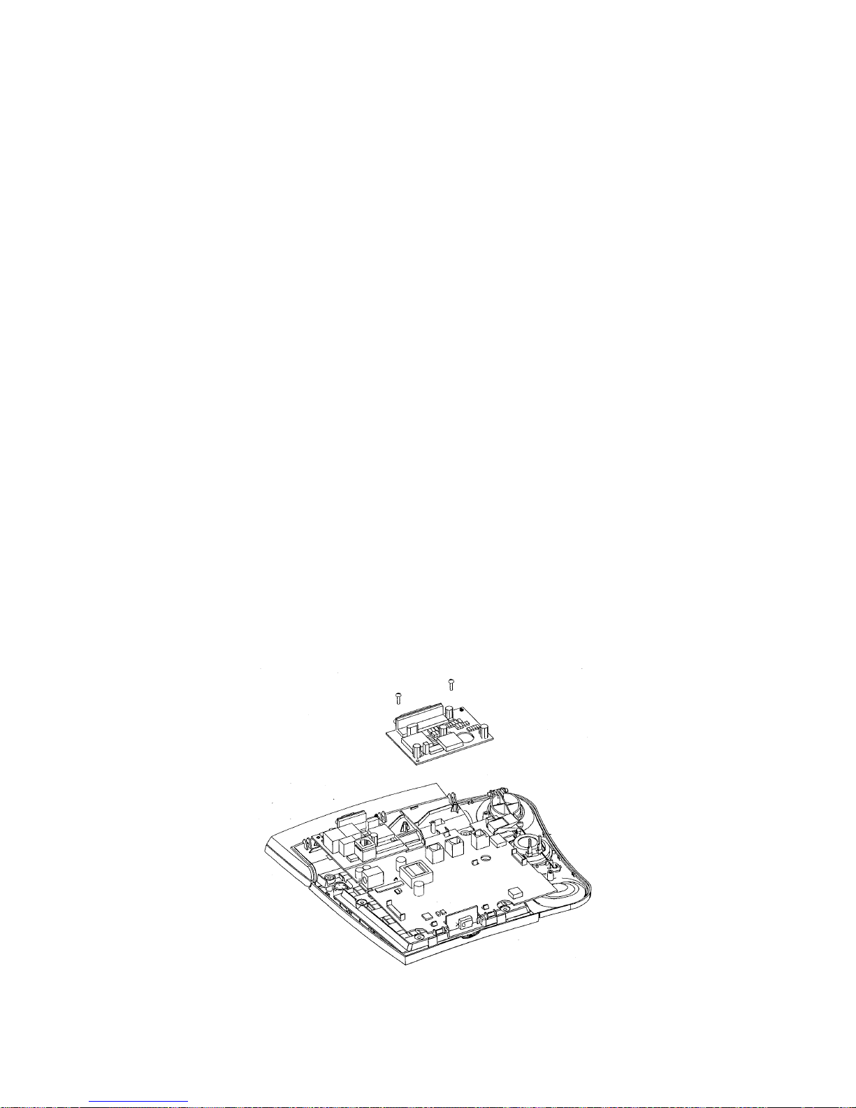
ErgoLine D330/D340
Customer Engineer Manual
Page 2-31
V.24 Interface Option
The ErgoLine D340 terminal has an optional V.24 Data Interface. This interface
conforms to the CCITT V.24/V28 recommendations for, respectively, the circuit
functions and electrical characteristics.
The V.24 Data Interface is an ISDN terminal adapter which enables
communication with a similar device. It is not designed to communicate with
modems, although modem commands can be used to control it. The V.24
interface behaves as a DCE and the connected V.24 equipment behaves as a
DTE.
Note
: The V.24 option requires an external power supply to be fitted.
Installing the V.24 Data Interface
To install a Data Interface in the ErgoLine terminal, proceed as follows:
WARNING
: Do not open the ErgoLine terminal when either the line or
external power supply are connected.
1. Turn the terminal upside down.
2. Remove the line cord (if connected).
3. Remove the DSS/DSS. This is attached by two screws in the base of the
terminal.
4. Remove the external power supply (if fitted).
5. Remove the handset plug and any auxiliary equipment fitted to the audio or
static interface.
6. Remove the base of the terminal. A few screws fasten the base to the terminal.
One of the screws is located under the DSS cover.
7. Install the V.24 Data Interface as shown.
F
IGURE
2-5. I
NSTALLING THE
V.24 I
NTERFACE
Page 52
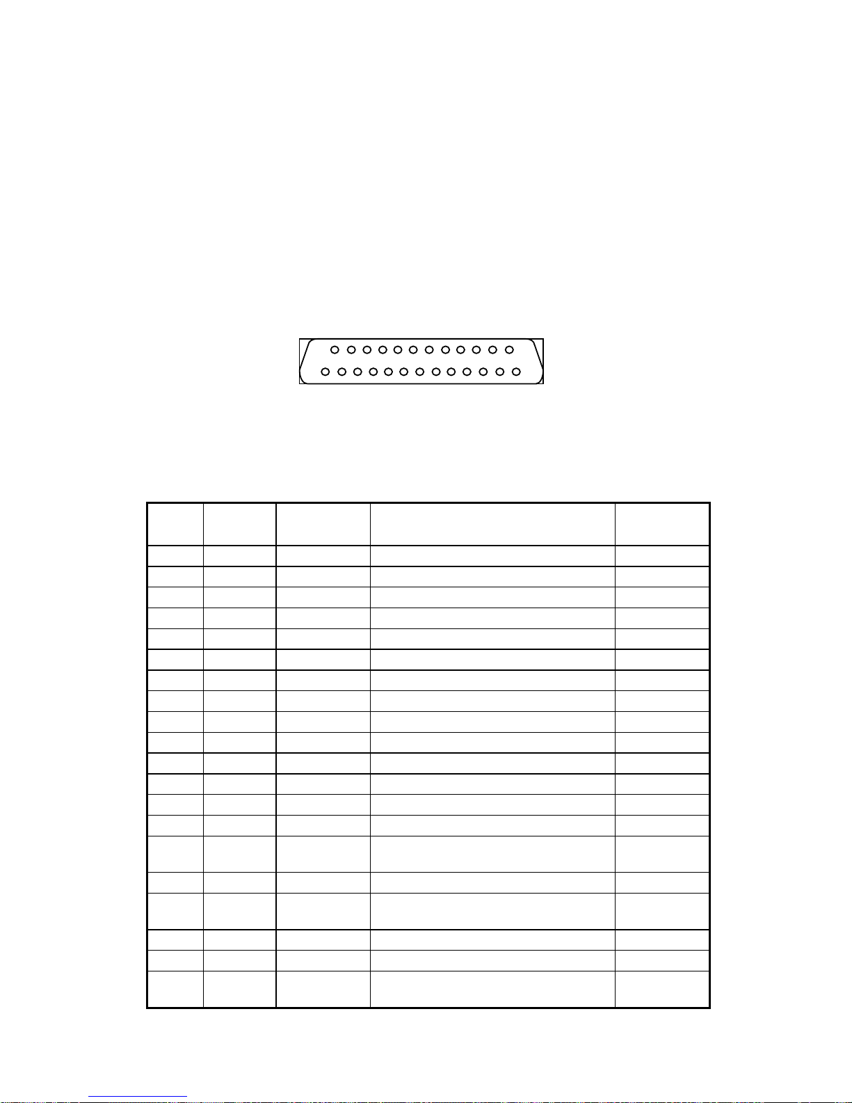
ErgoLine D330/D340
Customer Engineer Manual
Page 2-32
8. Replace the base and secure with screws.
9. Replace any auxiliary equipment and replace the handset plug.
10. Replace or fit the external power supply.
11. Replace the DSS/DSS cover.
12. Program the TEI to 0&1 via the Service Mode program.
13. Replace the line cord.
Connection to the V.24 interface is via a 25 pin D-type female connector (ISO
2110 specification) on the rear of the ErgoLine D340 main terminal unit.
F
IGURE
2-6. V.24 I
NTERFACE CONNECTOR PIN LAYOUT
T
ABLE
2-7. V.24 P
IN CONFIGURATION
PIN CIRCUIT MNEMONIC DESCRIPTION
TO/FROM
DCE
1 - - N/C 2 103 TD Transmitted data to
3 104 RD Received data from
4 105 RTS Request to send to
5 106 RFS Ready for sending from
6 107 DSR Data set ready from
7 102 GND Signal ground / common return 8 109 DCD Data carrier detect from
9 - - N/C 10 - - N/C 11 - - N/C 12 - - N/C 13 - - N/C 14 - - N/C 15 114 TSET
Transmitter signal element timing
(DCE source)
from
16 - - N/C 17 115 RSET
Receiver signal element timing (DCE
source)
from
18 141 LL Local loopback to
19 - - N/C 20
108.1
108.2
CDSL
DTR
Connect data set to line
Data terminal ready
to
to
14
1
25
13
Page 53
ErgoLine D330/D340
Customer Engineer Manual
Page 2-33
PIN CIRCUIT MNEMONIC DESCRIPTION
TO/FROM
DCE
21 140 RL Loopback / maintenance test to
22 125 CI Calling indicator from
23 - - N/C 24 113 TSET Transmitter signal element timing
(DTE source)
to
25 142 TI Test indicator from
Data Call Control
To switch the telephone from Voice-mode to Data-mode press SHIFT and then
ARROW RIGHT.
To switch the telephone from Data-mode to Voice-mode press SHIFT and then
ARROW LEFT.
It is also possible to program a key by means of which the user can switch
between Voice and Data modes.
There are four methods of call control available. These must be configured using
the ErgoLine D340 keypad.
1. Telephone Keypad
The call can be established by dialling from the ErgoLine D340 keypad only.
Messages from the ErgoLine terminal will not be transmitted to the attached
V.24 equipment and cannot be seen.
2. DTE Keyboard
The call can be established from both the keyboard of the V.24 device and
from the keyboard of the ErgoLine D340. An incoming call will automatically
be answered if the attached V.24 equipment is powered off or is switched on
when the call is being received at the ErgoLine D340. DTR is active when the
equipment is powered.
3. V.25bis
Calls can be controlled from the attached V.24 equipment using the CCITT
V.25bis protocol, as described in the paragraph V.25bis Command and
Messages which follows.
4. Hayes
Calls can be controlled from the attached V.24 equipment using Hayes
protocol, as described in the paragraph Hayes Command Registers and
Result Codes, which follows.
Dialling Options
•
Echo Characters
•
Convert to Upper case
Page 54
ErgoLine D330/D340
Customer Engineer Manual
Page 2-34
•
Display Calling Number
Data Transfer Parameters
The
baud rate
can be set up to the rates specified in the following table. This
transfer mode and rate adaptation are fixed for each baud rate. The rate must
match the baud rate of the attached V.24 device.
T
ABLE
2-8. D
ATA TRANSFER PARAMETERS
BAUD
RATE
TRANSFER
MODE
RATE
ADAPTATION
300 Asynchronous V.110
600 Asynchronous V.110
1200 Asynchronous V.110
1800 Asynchronous V.110
2400 Asynchronous V.110
4800 Asynchronous V.110
9600 Asynchronous V.110
19200 Asynchronous V.110
38400 Asynchronous V.110
48000 Synchronous X.30
54000 Synchronous X.30
64000 Synchronous X.30
The
data word length
can be set to 7 or 8 bits. Odd, even or no parity can be
specified and the number of stop bits can be 1 or 2. The following table lists these
options. The settings must match the settings of the V.24 device to which the
ErgoLine D340 is connected.
T
ABLE
2-9. D
ATA BYTE SIZE
CHAR.
LENGTH
PARITY STOP BITS
8 bits none 1
8 bits even 1
8 bits odd 1
8 bits none 2
8 bits even 2
8 bits odd 2
7 bits none 1
7 bits even 1
7 bits odd 1
7 bits none 2
7 bits even 2
7 bits odd 2
Page 55

ErgoLine D330/D340
Customer Engineer Manual
Page 2-35
Line Protocols
1. Flow Control
The methods of flow control between the V.24 interface and the V.24 device
are configurable. There are two hardware methods and one software
method. These must be compatible with the method used by the attached
V.24 device.
The three methods are as follows:
•
RTS/CTS + DTR/DSR
•
RTS/CTS
•
CCITT (Xon/Xoff)
2. Connection Control
There are three configurable items:
•
BREAK CLEARS CALL ON/OFF
A break will cause the call to clear down.
•
DATA GUARDING TIME xx SECS
The call clears down after xx seconds without data being sent.
•
LOG OFF SIGN
The log off message sent to the attached V.24 device can be configured.
V.25bis Commands and Messages
The V.25bis commands are sent from the V.24 equipment and answered with a
corresponding message.
The ErgoLine D340 telephone discriminates between the operational state
command mode and the data transfer rate.
Initially the command mode is active, so commands can be given. After a
connection is established, the state changes to the data transfer state. In this
state no commands can be accepted.
The following settings are necessary for a successful operation.
•
Dial protocol V.25bis
•
Asynchronous mode
•
In the case that characters are double, or not seen at all on the V.24
equipment, select
local echo
on or off.
T
ABLE
2-10. V.25
BIS COMMANDS
T
HE FOLLOWING COMMANDS WILL BE ACCEPTED
Call request with number provided CRN
Disregard Incoming Call DIC
Connect Incoming Call CIC
Change from V.25bis to keyboard dialling EXI
Call in Voice Mode with number provided CRL
Page 56
ErgoLine D330/D340
Customer Engineer Manual
Page 2-36
T
ABLE
2-11. V.25
BIS MESSAGES
T
HE FOLLOWING MESSAGES WILL BE RETURNED
Call Failure Indication CFI
Incoming Call INC
Valid VAL
Invalid INV
Connection Established CNX
T
ABLE
2-12. C
ALL FAILURE REASONS
I
F A CALL FAILURE INDICATION IS RETURNED THE FOLLOWING REASONS MAY BE GIVEN
No answer RT
Busy ET
Hayes Commands Registers and Result Codes
The Hayes protocol allows the control of connections from the V.24 equipment in
exactly the same way as the V.25bis protocol.
Hayes also discriminates between the Command Mode and the Data Transfer
State. In a connection you can change back to the Command Mode with an
escape sequence (see Table 2-13).
The commands available in the ErgoLine D340 terminal are a subset of the Hayes
1200 Smart Modem commands.
T
ABLE
2-13. H
AYES COMMANDS
N
OT ALL HAYES COMMANDS ARE USED, BUT THE FOLLOWING WILL BE ACCEPTED
AT Command prefix must be given before all the
following commands (excluding A/)
A Answer a data call
A/ Repeat last command (without AT)
B Not used
C Not used
D<number> Dials the given number. If there is a semi-
colon
( ; ) after the command, other commands
may follow
E0 Local echo OFF
E1 Local echo ON
F Not used
H0 Hang up
H1 Not used
H2 Not used
I0 Returns the software version number
I3 The Hayes parameters are reset to factory
default settings
L Not used
M Not used
O1, O2, O3 Return from Command Mode to Data
Transfer Mode
P Not used
Page 57
ErgoLine D330/D340
Customer Engineer Manual
Page 2-37
Q0 Not used
Q1 Not used
Q2 Not used
R Not used
Sr? Returns decimal value of register r
Sr=xxx Program register r with xxx. Returns OK if x
does not exceed the maximum value for r,
otherwise ERROR is returned.
T Not used
V0 Numeric indication of result codes
V1 Verbose indication of result codes
X0 Suppress all result codes
X1 Suppress result code 7
X3 No suppression of result codes
Y Not used
? Indicate the contents of the last read or
modified register
&E Change from AT mode to keyboard dialling
&V<number>Set-up a voice call
+++ Escape sequence (register S2). Change from
Data Transfer State to the Command Mode
without clearing the current connection.
Before and after the sequence, no data may
be transferred for 0.5 seconds. The sequence
itself must be received within 0.5 seconds
otherwise is invalid.
T
ABLE
2-14. R
EGISTER
S
OME OF THE REGISTER USED IN THE HAYES MODEM ARE NOT APPLIED IN THE ERGOLINE
D340. W
HEN NOT
USED
,
NOT IMPLEMENTED OR NOT MENTIONED REGISTERS ARE ACCESSED THE VALUE 0 WILL ALWAYS BE
RETURNED
.
A
LL PROGRAMMED VALUES BETWEEN 0 AND
255 (
DECIMAL) WILL BE ACCEPTED
.
S0 Value of S1 before a call is automatically
answered. The value 0 prevents automatic
answering of calls
S1 Count of ring signals in 2 second steps until
the call is automatically answered. (The call
will be answered when the value of S0 is
reached.)
S2 Character for escape sequence. Default is
ASCII 43 “+”
S3 Not used character for Carriage Return.
Default is ASCII 13
S4 Not used character for Line Feed. Default is
ASCII 10
S5 Not used character for Back Space. Default is
ASCII 8
S6 Not used Wait Time for Blind Dialling. Default is
ASCII 2
S7 Not used Wait Time for Carrier After Dialling.
The maximum wait time until the connection
is established is 120 seconds. Default is ASCII
30
Page 58
ErgoLine D330/D340
Customer Engineer Manual
Page 2-38
S8 Not used Pause Duration for Dial Delay. Not
supported. Default is ASCII 1
S9 Not used Reaction Time to Received Carrier.
Default is ASCII 6
S10 Not used Time Delay from Loss of Carrier to
Clearing of Connection. The synchronisation
may be lost for up to 3 seconds.
Default is ASCII 7
S11 Not used Duration and Interval of the MFV-
Tone. Default is ASCII 70
S12 Maximum Supervision Time for an escape
sequence. Default is 0.5 seconds (the time is
given in hundredths of a second)
Note: S6 to S11 are not applicable to ISDN/Digital terminals
T
ABLE
2-15. R
ESULT CODES
N
OT ALL OF THE HAYES RESULT CODES ARE USED
. R
ESULT CODES ARE SENT AS REACTIONS TO COMMANDS
OR MESSAGES FROM THE
S
WITCH
. I
F AND WHEN THE RESULT CODES ARE EXPRESSED DEPENDS UPON THE
APPLIED
V
COMMANDS
(V0 & V1)
AND THE X COMMANDS
(X0, X1 & X3).
0 OK Command executed
1 CONNECT Connected at 0 .. 300 bit/s
2 RING Incoming call
3 NO CARRIER No synchronisation or synchronisation lost
4 ERROR Error in given command
5 CONNECT 1200 Connected at 1200 bit/s
7 BUSY Busy
10 CONNECT 2400 Connected at 2400 bit/s
11 CONNECT 4800 Connected at 4800 bit/s
12 CONNECT 9600 Connected at 9600 bit/s
13 CONNECT>xxxx Connected at xxxx bit/s (over 9600 bit/s)
Page 59
ErgoLine D330/D340
Customer Engineer Manual
Page 2-39
PC Interface Option
The PC Interface is standard on the ErgoLine D330 and D340. This PC interface is
used for driving the terminal via a PC allowing TAPI-compliant applications to be
used via this interface.
Connection to the PC Interface is via a 9 pin D-type female connector on the
rear of the ErgoLine main terminal unit.
F
IGURE
2-7. PC I
NTERFACE CONNECTOR PIN LAYOUT
T
ABLE
2-16. PC I
NTERFACE CABLE PIN CONFIGURATION
9-Way Terminal 9-Way PC 25-Way PC
Pin 2 Pin 2 Pin 3
Pin 3 Pin 3 Pin 2
Pin 5 Pin 5 Pin 7
Software Installation
A TAPI software driver will be provided on 3.5 inch floppy disk, enabling TAPIcompliant applications to be used via the interface. The TAPI driver is compatible
with Windows 3.1, Windows 3.11 and Windows 95.
To install the software, connect the ErgoLine terminal to your PC via the PC
Interface using a one to one cable. Install the software on the PC as follows:
Windows 95:
1. Insert the floppy disk into the disk drive.
2. In Windows 95, click
Start
then
Run
.
3. Type in
A:\setup
, then press the return key.
4. Follow the on-screen instructions to complete the software installation.
Windows 3.1/3.11
1. Insert the floppy disk into the disk drive.
2. From Program Manager select
File/Run.
3. Type in
A:\setup
in the dialog box, then press the return key.
4. Follow the on-screen instructions to complete the software installation.
69
5
1
Page 60
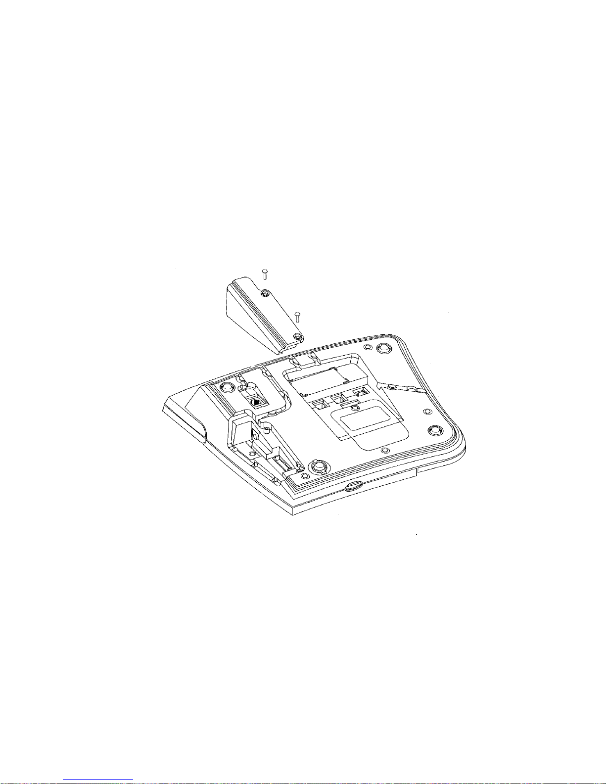
ErgoLine D330/D340
Customer Engineer Manual
Page 2-40
Installing the Direct Station Select (DSS) Options
Up to three DSS options can be added to an ErgoLine D340 terminal.
To install DSS options, proceed as follows:
Note
: The DSS module requires an external power supply to be fitted.
WARNING
: Do not fit the DSS module when line or external power is
connected.
1. Turn the ErgoLine terminal upside down.
2. Remove the line cord (if connected).
3. Remove the DSS/DSS cover from the base of the terminal by removing the
screws.
F
IGURE
2-8. I
NSTALLING THE
DSS O
PTIONS
4. Remove the external power supply if fitted.
5. Plug the DSS option into the slot in the base of the terminal or to the existing
DSS.
6. Fit the external power supply, routing the cable in the slot in the base.
7. If no further DSS modules are to be fitted, place the cover on the DSS module
and secure it with the screws.
8. Secure the DSS to the bottom case using the two screws provided.
Page 61
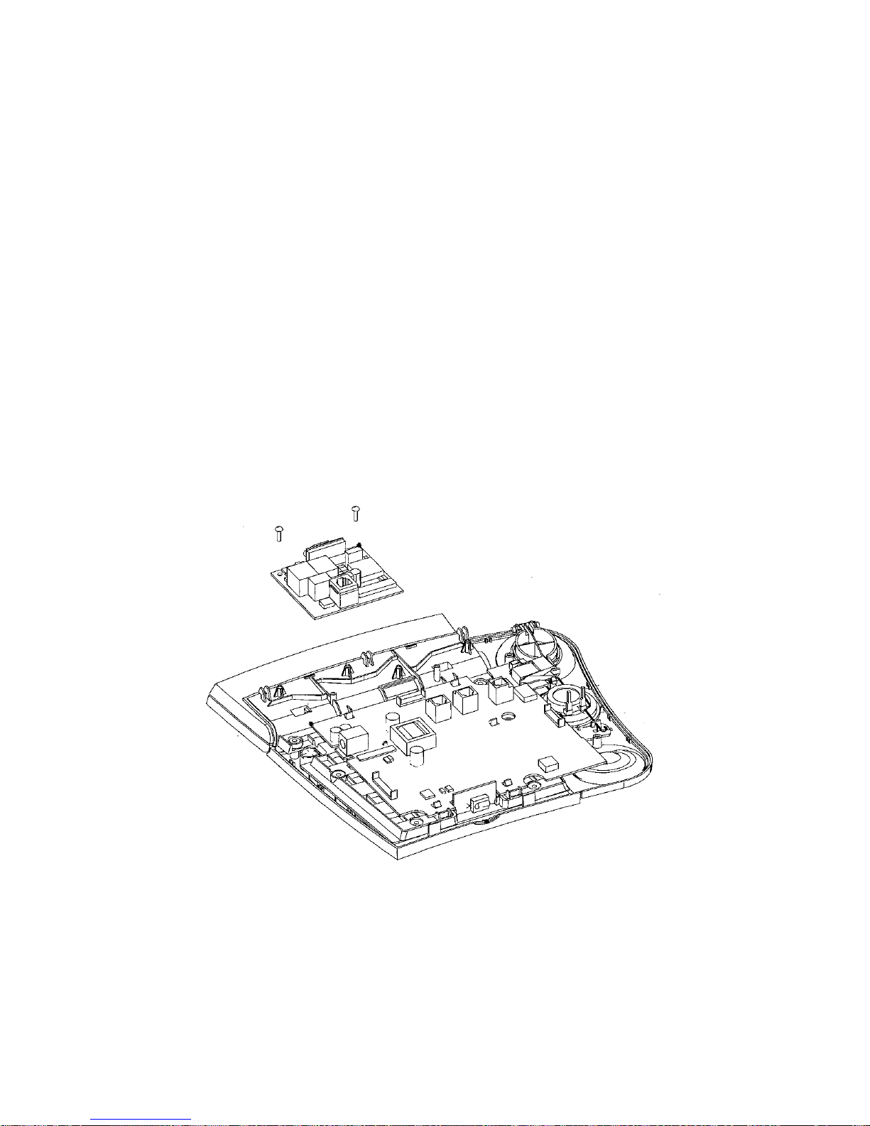
ErgoLine D330/D340
Customer Engineer Manual
Page 2-41
Installing Optional Line Interface
The ErgoLine terminal can be fitted with either a 2-wire or a 4-wire line interface.
To change the line interface, proceed as follows:
WARNING
: Do not open the ErgoLine terminal when line or external power is
connected.
1. Turn the terminal upside down.
2. Remove the line cord (if connected).
3. Remove the DSS cover, as described previously.
4. Remove the external power supply if fitted.
5. Remove the handset plug and any auxiliary equipment fitted.
6. Remove the base of the terminal. The base is fastened to the terminal with
screws, one of which is located under the DSS cover.
7. Remove the existing interface.
8. Install the optional line interface as shown. Make sure that the board is secured
using the screws provided.
F
IGURE
2-9. I
NSTALLING THE OPTIONAL LINE INTERFACE
9. Replace the base cover of the terminal and secure it with the screws.
10. Replace any auxiliary equipment and handset plug.
11. Replace the line cord.
Page 62
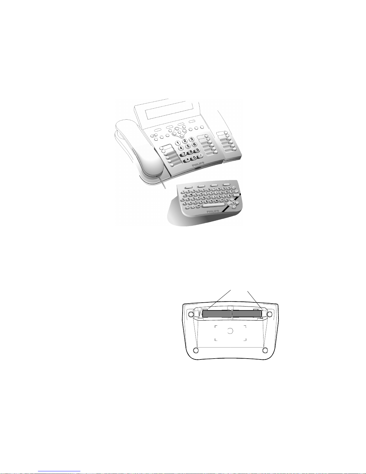
ErgoLine D330/D340
Customer Engineer Manual
Page 2-42
ASCII Keyboard
The ErgoLine D340 terminal can have, as an option, a separate ASCII keyboard. It
communicates with the ErgoLine terminal via an Infra-Red link.
Note
: If no ASCII keyboard is in use, it is recommended that the ASCII keyboard
setting is switched off (this is the default condition). Other infra-red office
equipment may activate the infra-red detector.
F
IGURE
2-10. ASCII K
EYBOARD
Power
The ASCII keypad is powered by two AAA batteries. The batteries are installed as
follows:
1. Open the battery cover on
the rear of the keypad.
2. The batteries are installed as
shown. Make sure the
batteries are installed in the
correct polarity positions.
3. Replace the battery cover.
F
IGURE
2-11. C
HANGING THE BATTERIES IN THE
ASCII K
EYPAD
Polarity: - +
Page 63
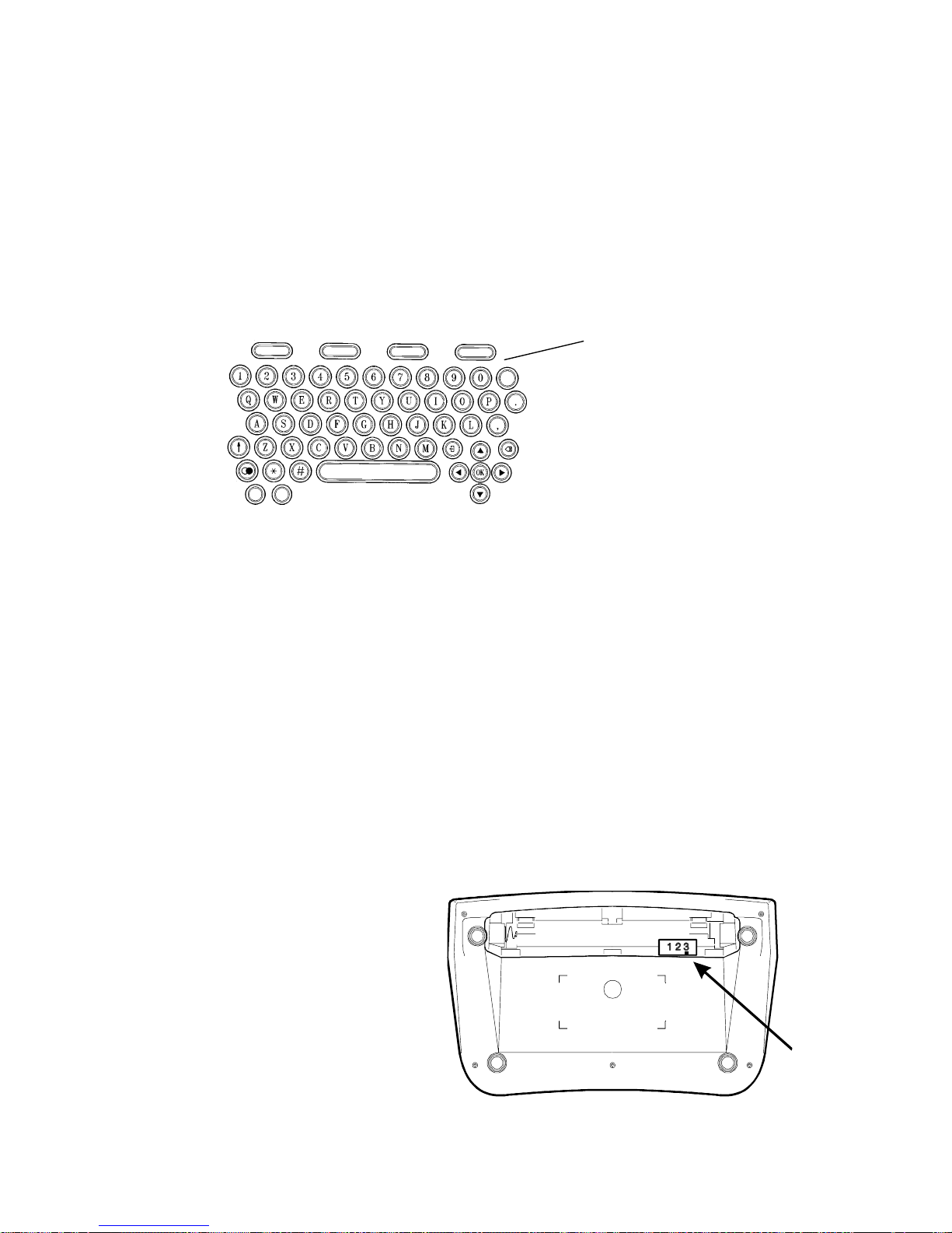
ErgoLine D330/D340
Customer Engineer Manual
Page 2-43
International Character Selection
International characters can be selected on the ASCII keypad by pressing the
grey key, located at the top right of the keypad, followed by one of the keys
marked with a coloured circle. (For example, to select the character è, press the
grey key then the E key. Continued pressing of the E key will toggle through the
choices available for this key combination.) If a message contains special
characters, these special characters can be received by other equal ErgoLine
terminals. However they cannot be received by SOPHO Sets or the SOPHO DECT
handsets.
Relationship of Keys on ASCII Keyboard to Terminal Keys
The following keys perform the same function on the ASCII Keyboard as the
equivalent keys on the ErgoLine terminals. Those keys are: Exit, Backspace, Cursor
Keys, OK , LNR, Shift and the Softkeys. Refer to the User Guide for details.
Channel Selection
The ASCII Keypad can communicate with the ErgoLine terminal over one of three
channels. When selecting a channel, take note of the channels being used by
other ErgoLine terminals and ASCII Keypads working nearby. Select a channel
which will not interfere with the operation of other terminals.
To select a channel for the ASCII Keypad, proceed as follows:
1. Open the battery cover on the rear of the ASCII Keypad.
2. Remove the batteries.
3. Using a narrow object (such as
the point of a pen) set the
slide switch to channel 1, 2 or
3 as required. The default
setting is 3 on both terminal
and ASCII keyboard.
4. Replace the batteries.
5. Replace the battery cover.
6. Set up the ASCII channel on
the ErgoLine terminal to match
the keypad channel setting via the softkey menu.
International Character
Selection Key (coloured grey)
F
IGURE
2-12. I
NTERNATIONAL CHARACTER SELECTION
Page 64
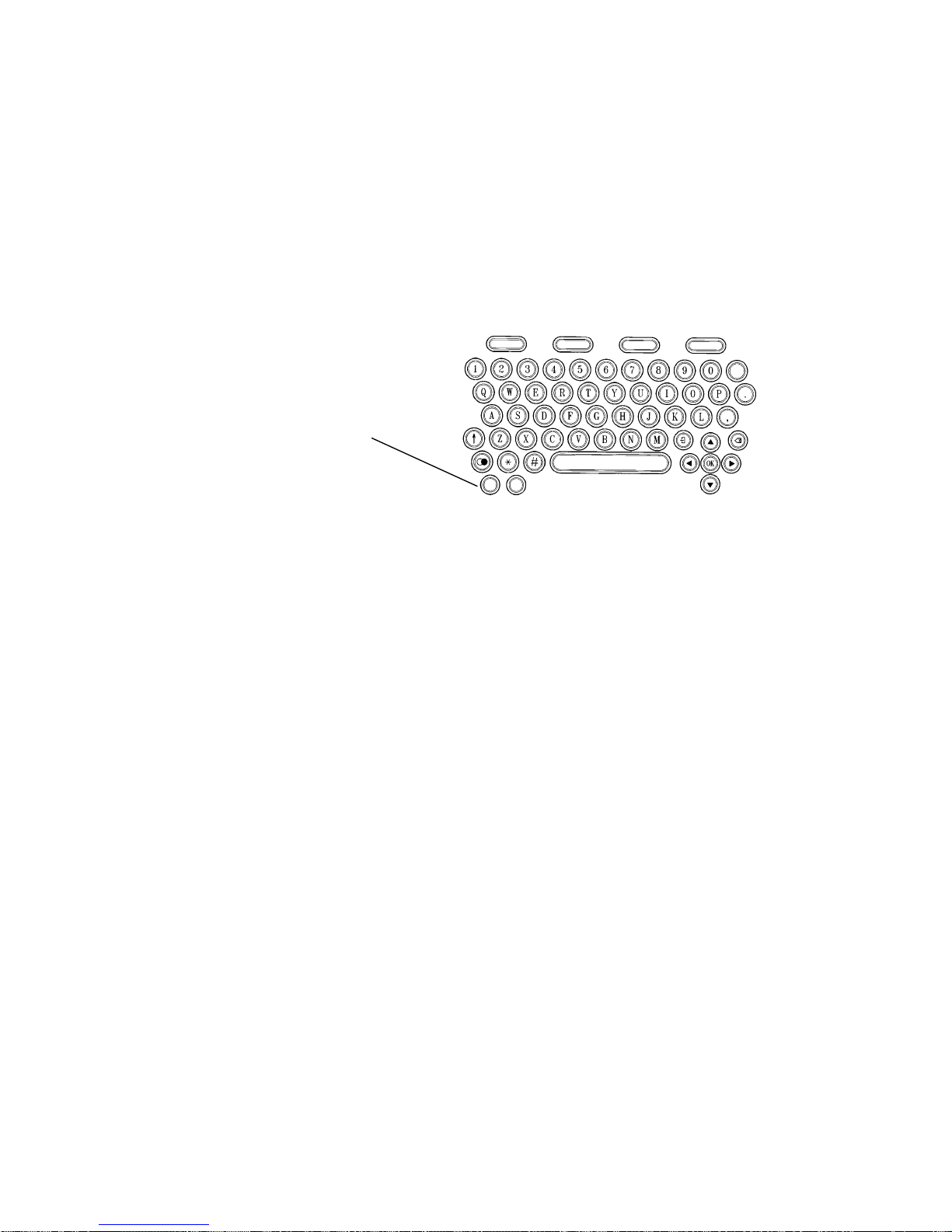
ErgoLine D330/D340
Customer Engineer Manual
Page 2-44
F
IGURE
2-13. S
ETTING THE CHANNEL ON THE
ASCII K
EYPAD
Function Key Numbering
As with the ErgoLine main terminal and the DSS options, the ASCII keypad has
programmable function keys. These two keys are not downloadable but are
programmable on both first and second levels.
The function keys are located at the bottom left hand side of the ASCII keypad,
and are annotated as M1 and M2. Figure 2-14 shows details of the function key
numbering.
F
IGURE
2-14. ASCII K
EYPAD FUNCTION KEY NUMBERING
(T
HE FORMAT USED TO DESCRIBE THE NUMBERING IS AS FOLLOWS
:
UI = U
SER INTERFACE MARKING ON THE TERMINAL
P
ROGRAMMABLE FUNCTION KEYS
UI = M1 UI = M2
Page 65
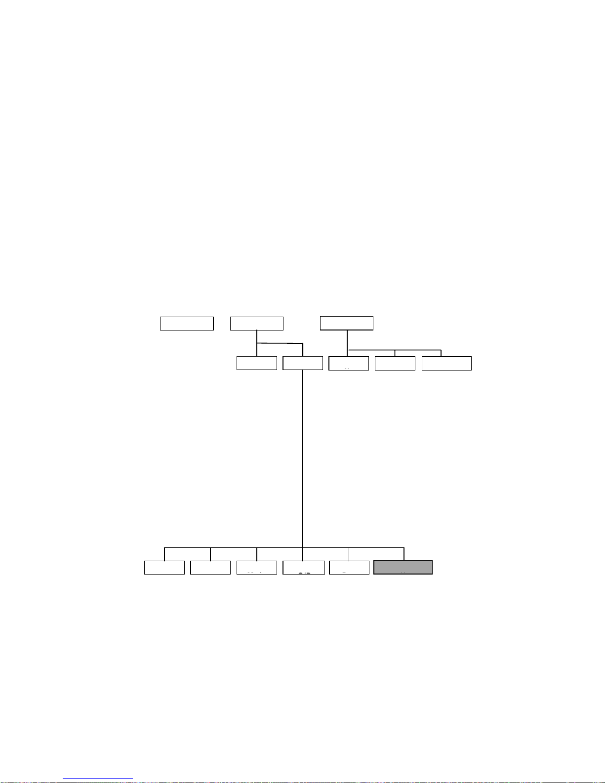
ErgoLine D330/D340
Customer Engineer Manual
Page 3-1
P
ROGRAMMING TELEPHONE PARAMETERS
Programming of the ErgoLine terminal is menu-driven. Navigation through the menus
is done using the cursor keys on the ErgoLine D330 terminal, or via the four Softkeys
on the ErgoLine D340 terminal. The Softkeys on the optional ASCII keypad behave in
an identical manner to the Softkeys on the D340. The terminal must be in the idle
condition, i.e. the handset is on-hook and the loud-speaker is de-activated, during
programming.
Programming can also be done remotely by means of a downloading procedure
from the ISPBX.
ErgoLine D330 Programming Map
When programming the ErgoLine D330, use the following map to navigate
through the various menu levels. Details of each programmed function is
contained in the User Manual.
Note
:
•
Options marked * are only available in Special mode. The Special
mode password is
2468
.
•
Options marked ** are only available in Service mode. The Service
mode password is
12687
.
DIRECTORY FEATURES
Toggle List Set Phone
Speeddial
Function
Group Facility
• ringer
• softring
• call wait. beep
• autom. answering
• autom. answering
for 1h.
• one key call setup
• store divert. calls
• callers list
• do not disturb
• night mode *
• incoming intercom
• microphone for
intercom
• status monitoring
• TAPI (phone)
• Loudring f. 3-softr
• speeddial
nr.
• Divert all calls
• call-back
• divers. on busy
• do not disturb
• night mode *
• DTMF
• message waiting
• call wait. beep
• autom. answering
• ringer
• on/off hook
(voice)
• Direct Password
• PFM *
• autom. answering
for 1h.
• handset without
hook
• headset
• push to talk **
• TAPI (phone)
• absent for calls
• group absence
• incoming intercom
• softring
• status monitoring
• show
absent/present
• group facility
• line key *
• groupmember
(intercom)
• private calls
• personal calls
• executive calls
• groupmember
calls
• group calls
• private park
• group park
• alternative
secretary
Change
Set Voice
Select
Set RingerLanguage
Service issues *
/
• english
• deutsch
• nederlands
• francais
• set volume
• set melody
• enter
password
• handset
with hook
• handset
w/out hook
• headset
• enter
old/new
password
& verify
• clear all keys
• clear directory
• reset togglelist
• do maintenance **
• set TEI
• download request **
• find ?
• add entry
• modify entry
• remove entry
KEYS
Page 66
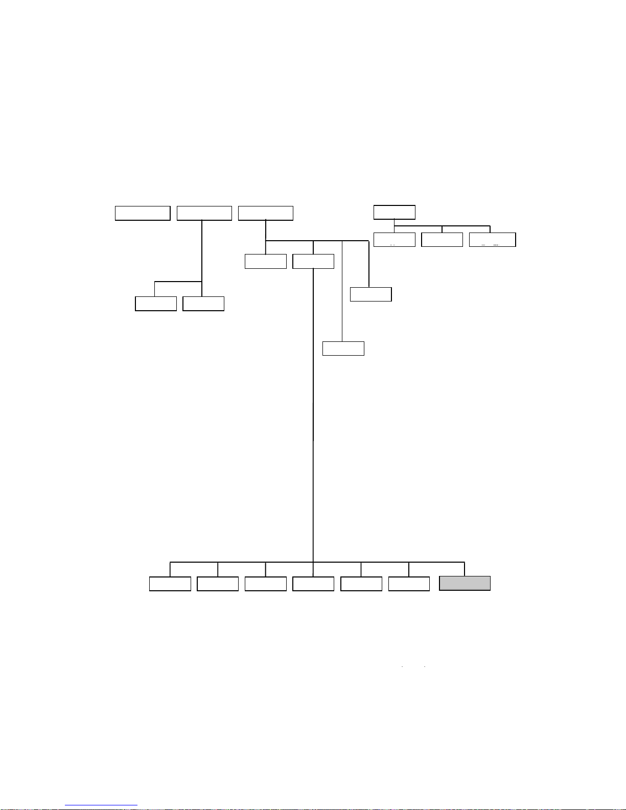
ErgoLine D330/D340
Customer Engineer Manual
Page 3-2
See User Guide for details.
ErgoLine D340 Programming Map
When programming the ErgoLine D340, use the following map to navigate
through the various menu levels. Details of each programmed function is
contained in the User Manual.
Note
:
•
Options marked * are only available in Special mode. The Special
mode password is
2468
.
DIRECTORY
MESSAGE FEATURES
Toggle List Set Phone
KEYS
Speeddial
Function Group
•
ringer
•
softring
•
call waiting beep
•
automatic answering
•
autom answering for
1h.
•
voice mode after
termination
•
one keystroke call setup
•
store diverted calls
•
callers list
•
do not disturb
•
night mode *
•
incoming intercom
•
micr. for intercom
•
status monitoring
•
footpedal *
•
second bell *
•
light doorlamp when
busy *
•
TAPI: speech via
accessory
•
TAPI: speech via
phone
•
enter
number
•
diversion of all calls
•
call-back
•
diversion on busy
•
do not disturb
•
night mode *
•
DTMF-tones
•
switch voice/data
mode
•
on/off hook key for
data
•
message waiting
indication
•
call waiting beep
•
automatic
answering
•
Ringer is off
•
on/off hook key for
voice
•
PFM *
•
direct password
•
notice
•
autom answering
for 1h
•
footpedal *
•
second bell *
•
light doorlamp
when busy *
•
light doorlamp
(manually) *
•
dooropener *
•
X-input instead of
mic.*
•
handset without
hookswitch
•
headset
•
TAPI: speech via
accessory
•
push to talk **
•
TAPI: speech via
phone
•
absent for most
calls
•
absent for group
calls
•
incoming intercom
•
softring
•
status monitoring
•
show absent/
present status
•
group facility
•
line key *
•
groupmember calls
per intercom
•
private calls
•
personal calls
•
executive calls
•
groupmember calls
•
group calls
•
private park
•
group park
•
diversion to
alternative secr.
PasswordVoice outSetModeSoundsLanguage Keyboard
•
english
•
deutsch
•
nederlands
•
francais
•
volume
•
melody
•
enter
password
•
handset with
hookswitch
•
handset
without
hookswitch
•
headset
•
enter
old/new
password
& verify
•
ASCII
keyboard
•
Infrared
channel
•
keyboard type
•
keyboard
keyclick
•
autorepeat
delay
•
find ?
•
add entry
•
modify entry
•
remove entry
Diversion
•
to one specific
extn
•
prep diversion to
variable extn
•
from other extn to
this phone
Notice Text
Callers
•
switch
on/off
•
list of
callers
Service * / **
•
download
request
•
set TEI **
•
clean
•
clear all keys
•
clear
directory
•
clear
message
•
reset data
•
reset toggle
list
All Costs
•
display charging
info
•
restart
Page 67

ErgoLine D330/D340
Customer Engineer Manual
Page 3-3
•
Options marked ** are only available in Service mode. The Service
mode password is
12687
.
See User Guide for details.
Terminal Locking and Unlocking of the D330/D340
The user is able to lock the set using LOCK MODE. Consult the User Guide on how
to do this. The default password for Lock Mode is 111. This can be changed by
the user.
Reset Lock password to default
If the user forgets the password, the following steps must be taken to reset the
password to the default:
1. Enter the service password again to enter Service mode.
2. Go to the password option in the Set phone menu and enter the default
password.
3. Verify the default password and exit service mode.
The Lock password is now returned to default.
Unlock the terminal the moment the password is not known
If the terminal is locked and the password is forgotten, the phone can be
unlocked as follows:
1. Press Lockoff
2. Enter the Service password (12687)
The set will return to user mode.
Perform the procedure outlined in steps 1-3 above to reset the Lock password to
default.
Page 68

ErgoLine D330/D340
Customer Engineer Manual
Page 3-4
Page 69

ErgoLine D330/D340
Customer Engineer Manual
Page 4-1
M
AINTENANCE AND TESTING
The following functional tests of the ErgoLine D330 & D340 terminals allow the Display,
Keyboard, LEDs, Memory, EEPROM, Analogue Interfaces and Digital Interfaces to be
tested. During the testing incoming calls can still be accepted.
Selecting a Test
Maintenance tests can only be done by entering the specific maintenance
codes for a test via the keyboard.
All tests must be done manually. It is not possible to perform tests automatically.
Selecting a Test by Entering the Code
1. Press the following (soft) keys in sequence:
•
FEATURES
•
SETPHONE
•
SETMODE
2. Enter the Service Engineer’s password, 12687
3. When the display returns to idle, press the following keys in sequence:
•
SHIFT
•
HOLD
Scroll right (ErgoLine D340) Scroll down (ErgoLine D330)
•
MAINTAIN
To activate a test or maintenance function, enter the test code and press OK.
When complete, press the CANCEL softkey on D340 or the EXIT key on D330 to
finish.
Page 70

ErgoLine D330/D340
Customer Engineer Manual
Page 4-2
Test codes and descriptions are as follows:
Show Software Version (Codes 1….. 6)
Code 1 : displays the version number of the terminal software EPROM.
Code 2 : displays the version number of the terminal key controller.
Code 3 : displays the version number of the key controller in DSS module 1
Code 4 : displays the version number of the key controller in DSS module 2
Code 5 : displays the version number of the key controller in DSS module 3
Code 6 : displays the version number of the V24 data module, where fitted.
Display Test (Code 11)
The display will show the complete dot matrix for approx. 3 seconds and then
clear.
Keyboard Test (Code 12)
Press each key in turn to display the key code on the LCD.
Refer to tables of key codes in the Function Key Downloading section.
LED Test : all LEDs on (Code 13
1
)
This test switches on all LEDs. The test code must then be re-entered to switch the
LEDs back off (toggle function)
WARNING
: If the test code is not re-entered, and the set is returned to user
mode, the LEDs will remain on indefinitely.
LED Test : all LEDs flashing (Code 14
1
)
This test flashes all LEDs on and off simultaneously. The test is aborted on
cancelling.
Page 71

ErgoLine D330/D340
Customer Engineer Manual
Page 4-3
Memory Test (Codes 21… 27)
Code 21 : verifies that RAM is operational
Code 22 : verifies the checksum for each bank of ROM
Code 23 : tests the EEPROM of the terminal for faulty memory cells
Code 24 : tests the EEPROM of DSS module 1 for faulty memory cells
Code 25 : tests the EEPROM of DSS module 2 for faulty memory cells
Code 26 : tests the EEPROM of DSS module 3 for faulty memory cells
Code 27 : displays the number of faulty memory cells in the terminal EPROM
EEPROM Erasure (Codes 31… 34)
Code 31 : erases the terminal EEPROM
Code 32 : erases the EEPROM of DSS module 1
Code 33 : erases the EEPROM of DSS module 2
Code 34 : erases the EEPROM of DSS module 3
WARNING
: Erasing the EEPROM deletes all user information and returns the set
to factory default status.
User settings can be removed and replaced using the maintenance tool
“ErgoLoad.”
See ErgoLoad package for operating instructions.
If the EEPROM is erased while connected to the iSPBX the set will be downloaded
with all switch settings.
Note
: It is also possible to erase the EEPROM by holding down keys *, 3 and 5
while removing and re-inserting the line cord (note : if mains power is also
connected, it should be removed before activating this sequence).
Note
: If the EEPROM is erased, the default TEI setting will be 0.
Analogue Interfaces (Codes 51, 53… 58)
Code 51 : tests the ringer volume
•
Press +/- to adjust the ringer volume.
Code 53
1
: tests the audio channel of the audio interface (X mode)
Code 541 : activates loopback test on handset
• Hold down hookswitch : handset mic feedback can be heard in handset receiver.
Code 55
1
: activates loopback test on hands-free
Code 561 : activates loopback test on loudhearing
Code 571 : activates forced transmit mode (toggle on/off)
Code 581 : activates forced receive mode (toggle on/off)
Page 72

ErgoLine D330/D340
Customer Engineer Manual
Page 4-4
Note
: Codes 57 and 58 are used in conjunction with the other codes.
It is essential that forced transmit or receive is deactivated off before
returning to user mode. See Note
1
on page 4-4.
Digital Interfaces (Codes 61… 70)
Code 61 : tests Y signal 0 on PC interface
Code 62 : tests Y signal 1 on PC interface
Code 63 : sends a signal from the PC interface at 1200 baud
Code 64 : tests X interface (activates X interface mirrored mode)
Code 65
1
: tests static interface signal 0
Code 661 : tests static interface signal 1
Code 671 : tests V24
Code 681 : tests line interface info_0
Code 691 : tests line interface info_1
Code 701 : tests B channel loopback (only when 2 B-channels available)
Note
1
: It is recommended that after any of these tests, a hardware reset is
completed.
Page 73

ErgoLine D330/D340
Customer Engineer Manual
Page 4-5
Call Progress Codes
During a call the ISPBX sends call progress codes to the ErgoLine D330/D340, see
Table 4-1. These codes are displayed on the left hand side and can be used as
an indication when tracing a fault.
T
ABLE
4-1. C
ALL PROGRESS CODES
CODES
MEANING
Accept
Facility registered
Answer
Answer
Busy
Number busy
Connect
Transferred
Congest
Congestion
Error
Procedure error
Incompt
Incompatible party
Reject
Facility rejected
Page 74

ErgoLine D330/D340
Customer Engineer Manual
Page 4-6
Page 75

ErgoLine D310/320
Customer Engineer Manual
Page 5-
1
I
NTRODUCTION
The Sopho ErgoLine D310 and D320 complete the new range of digital terminals for
use with the Philips iS3000 PABXs. The D310 and the D320 are designed to replace the
P171, P271 and S271.
The D320 and the D310 are both available with a 4-wire S0 interface and in a 2 wire
Upn interface.
(This line interface is not interchangeable like the D330 and D340!)
F
EATURES
The terminals have the following features:
ErgoLine D310
User Features
•
12 key numeric keypad
•
4 fixed function keys
•
last number redial
•
loudspeaker
•
loudspeaker volume control
•
ringer volume and ringer pitch control
•
listen in or loud hearing
•
on hook dialling
•
one keystroke call set up
•
optional key beep
•
message waiting lamp.
Keys
•
fixed function keys:
•
loudspeaker (including LED)
•
programming key
•
last number redial key
•
hold key
•
3 programmable keys for speed dialling
•
12 key numeric keypad.
Interfaces
•
Line interfaces:
•
4 wire S0 interface
•
2 wire Upn interface.
Accessories
•
Wall mounting plate which enables:
•
terminal to be mounted on a wall
•
adjustment of viewing/working angle of the terminal on a desktop.
Page 76

ErgoLine D310/320
Customer Engineer Manual
Page 5-2
ErgoLine D320
User Features
•
1x 16 character display
•
date and time display
•
calling number display
•
call charge and duration display
•
scratch pad (to store the number of the connected party)
•
6 fixed function keys
•
12 key numeric keypad, all of which can be used as speeddial keys
•
last number redial
•
loudspeaker (for listen in or hands free)
•
microphone (for hands free)
•
loudspeaker volume control
•
ringer volume and ringer pitch control
•
one keystroke call set up
•
headset mode
•
off line number preparation
•
optional key beep
•
message waiting lamp.
Keys
•
fixed function keys:
•
loudspeaker (including LED)
•
microphone mute (including LED)
•
programming key
•
shift key (including LED)
•
last number redial key
•
hold key
•
4 programmable keys which can be programmed at 2 levels
•
12 key numeric keypad.
Interfaces
Line interfaces:
•
4 wire S0 interface
•
2 wire Upn interface.
Accessories
•
Wall mounting plate which enables:
•
terminal to be mounted on a wall
•
adjustment of viewing/working angle of the terminal on a desktop.
Maintenance
•
Protection against unauthorised programming of parameters
•
Protection against unauthorised programming of EAZ.
Page 77

ErgoLine D310/320
Customer Engineer Manual
Page 5-
3
Quick Scan Card of ErgoLine Models D310 and D320
Description
ErgoLine D310
ErgoLine D320
Screen size not available 1 x 16
Adjustable screen - no
Soft keys none none
Programmable keys (attached label) 3 4 + 4
Functions down-loadable (under keys) no no
Programmable memory (hidden label) - Fixed function keys 4 6
Cursor: horizontal, vertical and OK key not available not available
Loudspeaker volume control yes yes
Handset volume control no yes
Loud hearing yes yes
Handsfree no yes
Mute no yes
Intercom no no
Headset operation not available available
Last number redial 1 1
Hold yes yes
Message waiting LED yes yes
Callers base not available not available
Answer back message (receive) not available not available
Answer back message (send) not available not available
Personal directory not available not available
Dial by name no no
Alphabet on keypad yes yes
Memo handling no no
User guidance via display no no
Width 205 mm 205 mm
Depth 190 mm 190 mm
Height 72 mm 72 mm
Colours available Dark grey & Light
grey
Dark grey & Light
grey
Static interface no no
Audio input/output no no
DSS module no no
Extra earpiece no no
V.24 data module no no
PC interface no no
separate QWERTY/QWERTZ no no
Digital 2-wire U
version for DLX-U
fixed fixed
Digital 4-wire S
version for DTX-I or PNT1
fixed fixed
Quick reference card not available not available
User guide (Multilingual) included included
Equivalent previous models P171 P271, S271
Page 78

ErgoLine D310/320
Customer Engineer Manual
Page 5-4
P
HYSICAL LAYOUT
See related userguide.
D
ES CRIPTION OF FUNCTIO NS
See related userguide.
Page 79
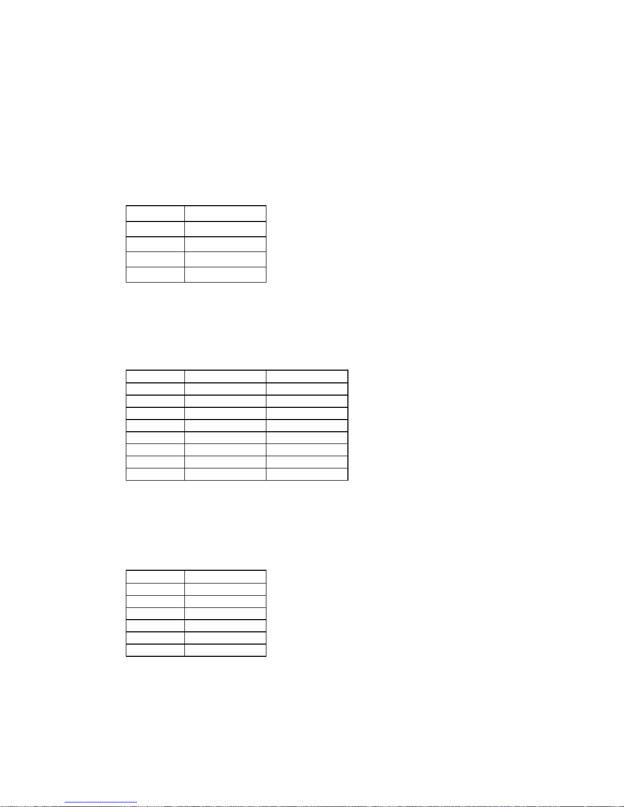
ErgoLine D310/320
Customer Engineer Manual
Page 5-
5
Installation
Cabling
Handset Cord
The handset is connected to the ErgoLine via a four wire coiled cord which terminates with a four way male modular plug at the terminal side.
Pin Outs
Pin Signal
1 Telephone
2 Microphone +
3 Microphone 4 Telephone
Terminal Line Cord D310-2W, D320-2W, D320-4W
On both ends the terminal line cord (normal length 6 m.) terminates with an eight
way plug. See diagram below.
Pin Outs
Pin
Signal/S
Signal/U
1 n/c n/c
2 n/c n/c
3 Transmit + n/c
4 Receive + a-wire (pos)
5 Receive - b-wire (neg)
6 Transmit - n/c
7 n/c n/c
8 n/c n/c
Terminal Line Cord D310-4W
On the wall plug end the terminal line cord (normal length 6 m.) terminates with
an eight way plug. See diagram above. The terminal end of the terminal line cord
ends with a 6 way plug. See diagram below.
Pin Outs
Pin
Signal/S
1 n/c
2 Transmit +
3 Receive +
4 Receive 5 Transmit 6 n/c
Note:
For more information on the hardware configuration of the
corresponding boards, see the Maintenance Manual for the iS3000, Part 3
Board Interfaces and Strap Settings, Chapter 4.
Page 80

ErgoLine D310/320
Customer Engineer Manual
Page 5-6
PNT1 (for use with 4-wire interface)
The ErgoLine D310 and D320 can be connected to the Switch via a Private
Network Termination (PNT1).
The EAZ of the ErgoLine D310/D320 should be adjusted as if the terminal was
connected to an S0-bus.
The PNT1 is equipped with two eight way modular sockets for the connection of
two S
0
ErgoLine terminals. On both jacks the corresponding pins 3, 4, 5 and 6 are
interconnected: 3 to 3, 4 to 4, etc.
Pin Outs
Pin
Signal
1 n/c
2 n/c
3 Receive +
(power +)
4 Transmit +
(power -)
5 Transmit -
(power -)
6 Receive -
(power +)
7 n/c
8 n/c
S
0
Interface
This interface is the standard SOPHO iS3000 S
0
interface.
To identify the terminal at the S
0
-bus see the section entitled
Endgerät Auswahl
Ziffer (EAZ)
below.
U
PN
interface
The ErgoLine D310 and D320 can be connected to the switch via the DLX-U U
PN
interface. This is a two wire digital interface which uses ping-pong signalling. (Do
not mistake this interface with the echo-cancelling proprietary Philips U-interface).
This interface is capable of supporting the connection of one terminal only.
Normally, the DLX-U U
PN
board should be projected in 1B mode for D310/D320
terminals.
The D310 and D320 terminal may also replace a D340 terminal that is connected
to a 2B+D mode projected DLX-U board. Remember that 2B+D mode is required
for the D340 when it uses both the voice and the data port. When a D310 or D320
terminal is connected to the DLX-U board in 2B+D mode only one B-channel is
used per port, while the other B-channel is left unused.
Page 81
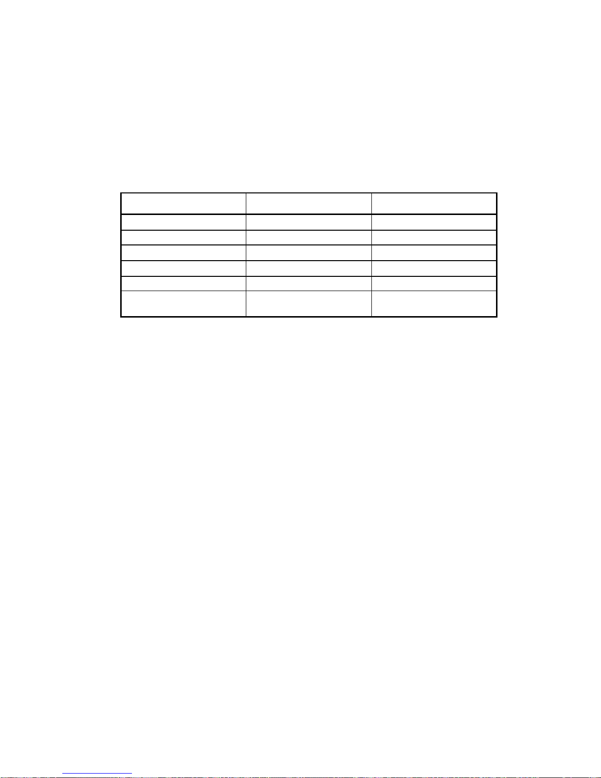
ErgoLine D310/320
Customer Engineer Manual
Page 5-
7
Cable and Distances
The S0 interface consists of two balanced twisted pairs, one pair for Transmit and
one pair for Receive. The distance between the ErgoLine and the Switch depends
upon the configuration and the cable characteristics of the cable used between
the wall socket and the Main Distribution Frame (MDF).
The U
PN
interface consists of one balanced twisted pair with half duplex operation
being used. The cable length is defined by cable type.
CHARACTERISTICS
S
0
SPECIFICATION UPN SPECIFICATION
Cable impedance
100
Ω at 96kHz
100
Ω at 192kHz
Wire diameter 0.5mm 0.5mm
Loop attenuation < 10dB / km at 96kHz
≤
26dB / km at 192kHz
Round trip delay
< 1 µsec / 100m max 23 µsec (total)
ErgoLine line cord length < 10m (normally 6m) 6m
ErgoLine line cord
connector
8 pin RJ45 according to
ISO 8877
8 pin RJ45 according to
ISO 8877
T
ABLE
5.1. T
YPICAL CABLE CHARACTERISTICS
For the possible wiring configurations, see the chapter “Cables and Distances” on
page 2-4 of the ErgoLine D330/D340 section of this manual. Note however that
the ErgoLine D310 and D320 cannot be connected to a DLC-C or DLC-D via a
PNT1.
Both twisted pairs must be terminated (preferable in the wall socket) with a 100
Ω
resistor.
Note 1
: When using a cable with cable characteristics different from the
ones listed in Table 5.1, the lengths of cable required will be different.
Note 2
: An intermediate MDF in the connection can also affect the overall
cable characteristics.
Note 3
: When cables are connected together additional attenuation,
caused by the joints, will occur.
When an ErgoLine D310 or D320 terminal is connected via a PNT1 to a DLC-U, the
distance can be extended by 1500 m. In this case the attenuation of the cable
used between the PNT1 and DLC may not exceed 15dB (at 100kHz, without noise
insertion).
Any combination of two ErgoLine models (D310, D320, D330 or D340) can be colocated. This means that different models (e.g. a D320 and a D340) may be
connected to the same S0 bus. They are identified by TEI or EAZ.
Connecting the ErgoLine Terminal
Connect the D310/D320 as follows:
•
connect the handset into the handset port, and put the handset on the
cradle
•
plug in the telephone line cord at the wall socket or the PNT1
Page 82

ErgoLine D310/320
Customer Engineer Manual
Page 5-8
•
the D310 emits two beeps within 5 seconds. It is now operational
the D320 displays the date and time ( or **-**-** if the date/time is not set in the
switch) within 10 seconds. It is now operational.
Endgerät Auswahl Ziffer (EAZ)
Terminals must have an “equipment end dialling code” (Endgerät Auswahl Ziffer)
for identification . The EAZ is used to determine:
•
which incoming calls, presented on the interface by the PABX, will be
accepted by the terminal in question
•
which terminal identification will be supplied for the PABX during outgoing call
set up. The PABX will determine the directory number with the aid of the EAZ.
Adjusting the EAZ for D320:
The two settings EAZ-1 and EAZ-2 are programmed as follows:
1 place the handset on hook
2 press PROGRAM key
3 press “9”
4 press PROGRAM key
5 EAZ-1and EAZ-2 are displayed:
6 enter a character to change the setting for EAZ-1. This character can be a
digit, 0 to 9, or *.
As soon as the first digit, EAZ-1, is entered the second digit, EAZ-2, is cleared.
7 press PROGRAM key to select this setting when EAZ-2 does not need to be
defined
8 if EAZ-2 is to be defined, enter the required character. This character can be
a digit, 0 to 9, or
*
9 press PROGRAM to store the new settings.
The default setting is:
EAZ-1 * and EAZ-2 -.
When EAZ-2 is not specified (-), the default setting is the value of EAZ-1
EAZ-1 EAZ-2 Outgoing call set up is
made with:
(See remarks)
Terminal accepts incoming
calls with:
‘0’-‘9’ ‘-‘ EAZ-1: ‘0’-‘9’ EAZ-1: ‘0’-‘9’
‘0’-‘9’ ‘0’-‘9’ EAZ-1: ‘0’-‘9’ EAZ-1: ‘0’-‘9’ or EAZ-2 ‘0’-‘9’
‘0’-‘9’ ‘*’ EAZ-1: ‘0’-‘9’ All incoming calls are
accepted
‘*’ don’t
care
‘0’ All incoming calls are
accepted
T
ABLE
5.2: EAZ
ADJUSTMENT FOR
D320
Page 83
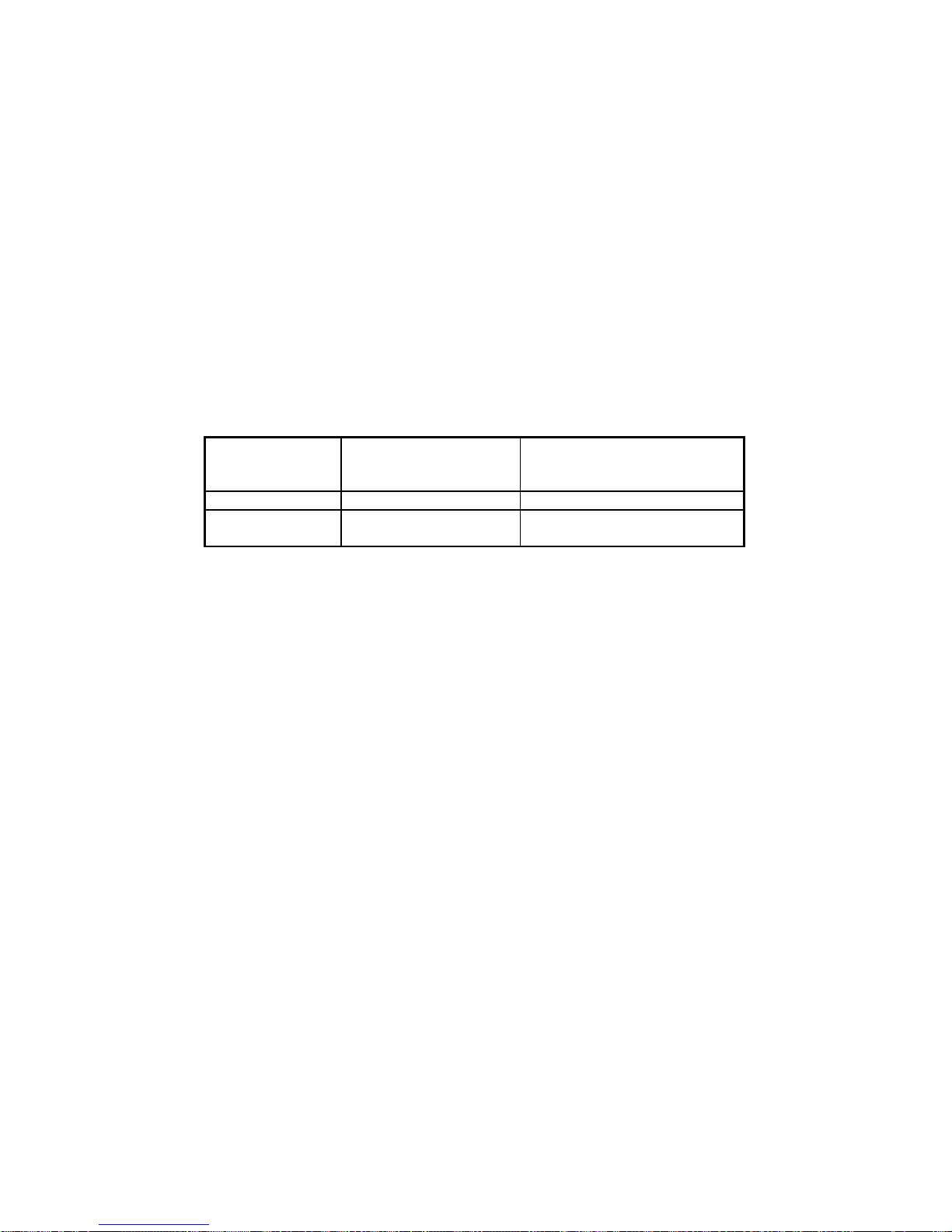
ErgoLine D310/320
Customer Engineer Manual
Page 5-
9
Adjusting the EAZ for D310:
The two settings EAZ can be programmed as follows:
1 place handset on hook
2 press PROGRAM key
3 press “9”
4 press PROGRAM key
5 press a character to change the setting for EAZ.
6 The character can be a digit, 0 to 9, or *.
7 Press PROGRAM key to select this setting
The default setting is ‘*’ for EAZ
EAZ Outgoing call set up is
made with: (see
remarks)
Terminal accepts incoming
calls with:
‘0’-‘9’ EAZ: ‘0’-‘9’ EAZ: ‘0’-‘9’
‘*’ ‘0’ All incoming calls are
accepted
T
ABLE
5.3: EAZ
ADJUSTMENT FOR
D310
Notes
:
•
On an outgoing call set up from the terminal, the PABX (of the iS3000 series)
looks for a directory number (DNR) that is defined for the U
PN
port or S0-bus and
that matches the EAZ. If not found the PABX continues to allocate any other
DNR at the U
PN
port or S0-bus that matches the service profile. So for a 2 wire
terminal, connected via the U
PN
interface, the EAZ (D310) or EAZ-1 (D320)
should be set as * or 2 (2 is the default value of the PABX). For EAZ-2 (D320) no
value needs to be specified.
•
A 4 wire terminal, connected via the S
0
interface, normally requires that the
EAZ (D310) or EAZ-1 (D320) of the first terminal be set to 2, and the EAZ (D310) or
EAZ-1 (D320) of the second terminal be set to 3. (Connecting 2 terminals in this
way is called co-location. Co-location is only possible with 4 wire terminals).
EAZ-2 is not required.
This is however not a rule. For example, if terminal-1 gets EAZ-1=2 and EAZ-2=3,
while terminal 2 gets EAZ-1=3 and EAZ-2=2, then on an incoming call for
terminal 1, terminal 2 will ring simultaneously. On an incoming call for terminal 2,
terminal 1 will ring simultaneously. The call can be answered by both terminal 1
and terminal 2. This is of course is only possible when terminals are co-located
and when these terminals support separate EAZ adjustment for incoming and
outgoing calls. Only the D320-4W supports both these conditions.
•
In case of malfunction (for example, incoming calls are not accepted, or the
terminal sets up calls with the wrong directory number) check the EAZ setting.
Page 84

ErgoLine D310/320
Customer Engineer Manual
Page 5-10
Programming
For full programming instructions, see the userguide.
It is also possible for the system engineer to protect the D320 against unauthorised
programming. This is done as described below:
Terminal (Un)locking of the D320
Terminal locking offers the possibility to block
•
programming of the EAZ only, or
•
programming of any parameters of the terminal by unauthorised users.
Locking of EAZ:
•
press PROGRAM key
•
press “159”
•
press PROGRAM key
•
press “1” to lock EAZ programming
•
press PROGRAM key.
It is now not possible to change the EAZ.
Unlocking of EAZ:
•
press PROGRAM key
•
press “159”
•
press PROGRAM key
•
press “0” to unlock EAZ programming
•
press PROGRAM key.
Locking of all programming
•
press PROGRAM key
•
press “159”
•
press PROGRAM key
•
press “9” to lock all programming
•
press PROGRAM key.
It is now not possible to change any setting of the terminal.
Unlocking of all programming:
•
disconnect terminal
•
press ‘4’ and ‘6’ key simultaneously while reconnecting the terminal.
Page 85

ErgoLine D310/320
Customer Engineer Manual
Page 5-
11
Maintenance
The following functional tests of the ErgoLine D330 & D340 terminals allow the
Display, Keyboard, LED’s, Memory and Interface to be tested.
Self test of the ErgoLine D310
If the terminal is powered up with the handset on hook and the '*' and '#' keys
pressed together a factory self test mode is entered. This mode clears all
programmed data and programming locks.
If the terminal is powered up with the handset on hook and the '7' and '9' keys
pressed together an installer self test mode is entered. This does a self test only. It
retains programmed data and locks.
After completion of a self test the terminal attempts a normal start-up.
Refer to Figure 5.1 for the names and locations of the keys.
The self test performs the following functions in sequence:
1 The micro-controller ROM is verified with a checksum.
2 The D310-2 external RAM is verified. Some of the D310-4 microcontroller RAM
is verified. If both ROM and RAM are satisfactory the loudspeaker LED begins
flashing, otherwise the self test halts and the phone will not try to go inservice.
3 The EEPROM is verified. If satisfactory the message waiting LED begins
flashing, otherwise the self test halts.
4 For factory self test the terminal settings and memory keys revert to their
defaults if the EEPROM check succeeds. For installer self test they are
retained.
5 The D310-2 U
p
interface is looped back internally and tested. If a fault
occurs, the self test halts and the loudspeaker LED is lit continuously.
6 The D310-2 IOM2 interface and CODEC are tested. If a fault occurs, the self
test halts and the message waiting LED is lit continuously.
7 The user next lifts the handset. The LEDs are extinguished.
8 Press keys in this order: Loudspeaker LNR 1 2 3 4 5 6 7 8 9 * 0 # Program M1
M2 M3 Recall.
9 After each key is detected in sequence a short beep is emitted. If an
incorrect key is pressed, an error beep is emitted. A pause of over 5 seconds
between keys results in an error beep.
10 The user now replaces the handset. At this point the ringer is sounded till the
user goes off-hook.
11 Lifting the handset finishes self test with a confidence beep and lets the
watch-dog expire to reset the D310. The set generates an outgoing call
request in response to the off-hook condition.
Page 86
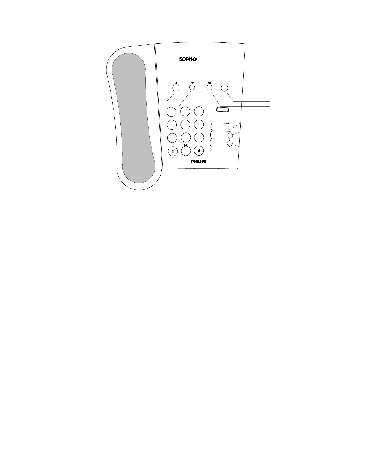
ErgoLine D310/320
Customer Engineer Manual
Page 5-12
ErgoLine
1
2
3
4
5
6
7
8
9
0
ABC
GHI
JKL
PQRS
TUV
MNO
WXYZ
DEF
Loudspeaker
Program
LNR
Hold
Memory Keys
M1
M2
M3
F
IGURE
5.1 D310
KEYS
Self test of the ErgoLine D320
If the terminal is powered up with the handset on hook and the '*' and '#' keys
pressed simultaneously a factory self test mode is entered. This self test mode
clears all programmed data and programming locks, and the message SELFTEST is
displayed.
If the terminal is powered up with the handset on hook and the '7' and '9' keys
pressed simultaneously an installer self test mode is entered. This performs a self
test only and does not clear programming data or locks, and the message
SELFTEST is displayed.
If the terminal is powered up with the handset on hook and the '4' and '6' keys
pressed simultaneously, all locks are cleared.
After completion of a self test the terminal attempts a normal start-up.
The self test performs the following functions in sequence. For tests 1 through 5 a
full stop character is appended to the display for each test completed. This
indicates progress of self test to the user.
Refer to Figure 5.2 for the names and locations of the keys.
1 The micro-controller ROM is verified with a checksum. If an error occurs then
the self test terminates and the message BAD CHKSUM is displayed.
2 The external RAM is checked. If an error is detected then the self test
terminates and the message BAD EXTERNAL RAM is displayed.
3 The EEPROM is verified. If a fault occurs then the self test is terminated and
the message BAD EEPROM is displayed
4 Note that for factory self test the terminal settings and memory keys revert
back to their defaults if the EEPROM check succeeds. For installer self test
the terminal settings and memory key contents are maintained.
5 The U
p
or S0 interface is looped back internally and tested. If a fault occurs,
the self test terminates and the message BAD HDLC/L1 is displayed.
Page 87
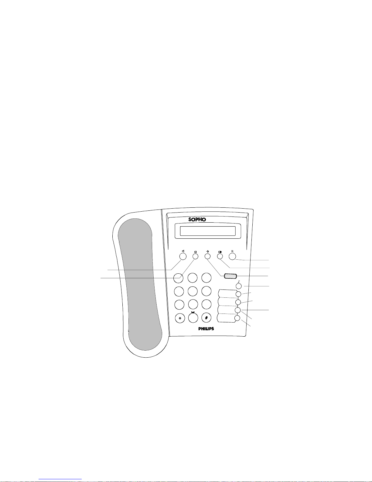
ErgoLine D310/320
Customer Engineer Manual
Page 5-
13
6 The IOM2 interface and CODEC are tested. If a fault occurs, the self test
terminates and the message BAD IOM2/CODEC is displayed.
7 If all the previous tests have been successful then all dot segments of the
dot matrix display are illuminated, all the LEDs are lit and a short beep is
emitted.
8 The user now lifts the handset and the display is cleared.
The user presses keys in this sequence: Loudspeaker Mute Program LNR Hold
1 2 3 4 5 6 7 8 9 * 0 # Shift M1 M2 M3 M4. Each key press is displayed.
9 After each key is detected in the sequence a short beep is emitted. If an
incorrect key is pressed then an error tone is emitted. A pause of more than
5 seconds between keys results in the same error tone being emitted. On
completion, all of the LEDs are extinguished.
10 The user must then replace the handset. At this point the ringer is sounded
with continuous ring at medium volume and using bi-tone ring until the user
goes off-hook.
11
Lifting the handset terminates the self test mode and lets the watch-dog
expire to reset the terminal. The terminal generates an outgoing call request
in response to the off-hook condition.
ABC
GHI
JKL
PQRS
TUV
MNO
WXYZ
DEF
ErgoLine
1
2
3
4
5
6
7
8
9
0
Loudspeaker
Mute
Memory Keys
Program
LNR
Hold
M1
M2
M3
M4
Shift
F
IGURE
5.2 D320
KEYS
Page 88

ErgoLine D310/320
Customer Engineer Manual
Page 5-14
 Loading...