

Page 1

EASY VISION RAD R4.2V2
LIST OF DOCUMENTATION IN THIS BINDER:
x SUBSYSTEM MANUAL
o
x
o
UNIT MANUAL Imager Compatibility
o
How to Read a DICOM Conformance Statement
Note:
LIST OF ALL BINDERS:
EasyVision RAD R4.2V2
x indicates document present
o
EasyVision RAD Release 4.2V2
4512 984 22362 REV AC 0.1
© 2003 Philips Medical Systems
ALL RIGHTS RESERVED
Page 2
E
W
INTRODUCTION AND TECHNICAL DATA
Philips Medical Systems
SERVICE MANUAL
732
SUBSYSTEM
1
EasyVision RAD R4.2V2
INSTALLATION
SETTING-TO-WORK
FAUTFINDING
REPLACEMENT
PROGRAMMINGS
2
3
4
5
6
ADJUSTMENTS
Printed in Hamburg, Germany
DMC Hamburg
© 2003 Philips Medical Systems
ALL RIGHTS RESERVED
EXPLANATIONS
DRAWINGS
7
8
9
10
11
4512 984 22362 REV AC 1
12
Page 3

EasyVision RAD 4.2V2
SERVICE MANUAL - SUBSYSTEM
EasyVision RAD R4.2V2 Author: C. Siems
In case there are any questions concerning this manual,
please send this LOPAD via fax to 49/(0)40/5078 2481
File: EasyVision RAD_22362AC
List of pages and drawings (LOPAD) Manual Order No: 4512 984 22362
released: 11/2003
__________________
0.1
1
3.1
__________________
1-1...1-9 (a/03.1)
__________________
2-1...2-12 (a/03.1)
__________________
3-1...3-14 (a/03.1)
__________________
4-1...4-30 (a/03.1)
_________________
5-1...5-10 (a/03.1)
__________________
6-1...6-26 (a/03.1)
__________________
7-1...7-4 (a/03.1)
__________________
8-1...8-14 (a/02.0)
__________________
______________________
Z0 (a/02.0) A4
Z2-1 (99.0) A3
Z2-2 (99.0) A3
Z2-3 (99.0) A3
Z2-3.1 (03.0) A3
Z2-3.2 (03.0) A3
Z2-3.3 (03.0) A3
Z2-3.4 (03.0) A3
Z2-3.5 (03.0) A3
Z2-4 (99.0) A3
Z2-5 (99.0) A3
Z2-6 (99.0) A3
Z2-7 (99.0) A3
Z2-8 (99.0) A3
Z2-9 (99.0) A3
Z2-10 (99.0) A3
Z2-11 (99.0) A3
____________________
4512 984 22362 REV AC 3.1
© 2003 Philips Medical Systems
ALL RIGHTS RESERVED
Page 4

Introduction And Technical Data Section 1
Section 1 Introduction & Technical Data
Contents
1.
INTRODUCTION..................................................................................................................................... 3
1.1. Documentation structure......................................................................................................................... 3
1.2. Technology.............................................................................................................................................. 4
1.3. Tools........................................................................................................................................................ 4
2.
PRODUCT DATA ................................................................................................................................... 5
2.1. Computers............................................................................................................................................... 5
2.2. Overview configuration............................................................................................................................ 5
2.3. Framebuffers........................................................................................................................................... 6
2.4. Monitors................................................................................................................................................... 6
2.5. Optical media drives................................................................................................................................ 6
2.6. Memory bank configurations................................................................................................................... 6
2.7. Connectivity............................................................................................................................................. 7
3.
EASYVISION RAD CONFIGURATIONS ............................................................................................... 8
3.1. PCR standalone Configuration ............................................................................................................... 8
3.2. PCR Multi Reader configuration ............................................................................................................. 8
4.
NETWORK CONNECTIONS .................................................................................................................. 9
4.1. Client Server Clusters ............................................................................................................................. 9
5.
SAFETY REQUIREMENTS .................................................................................................................. 10
5.1. Electrostatic Discharge ......................................................................................................................... 10
EasyVision RAD R4 (a/03.1) 1-1
Copyright © 1999-2003 Philips Medical Systems
ALL RIGHTS RESERVED
Page 5

Section 1 Introduction And Technical Data
1-2 (a/03.1) EasyVision RAD R4
Copyright © 1999-2003 Philips Medical Systems
ALL RIGHTS RESERVED
Page 6

Introduction And Technical Data Section 1
1. INTRODUCTION
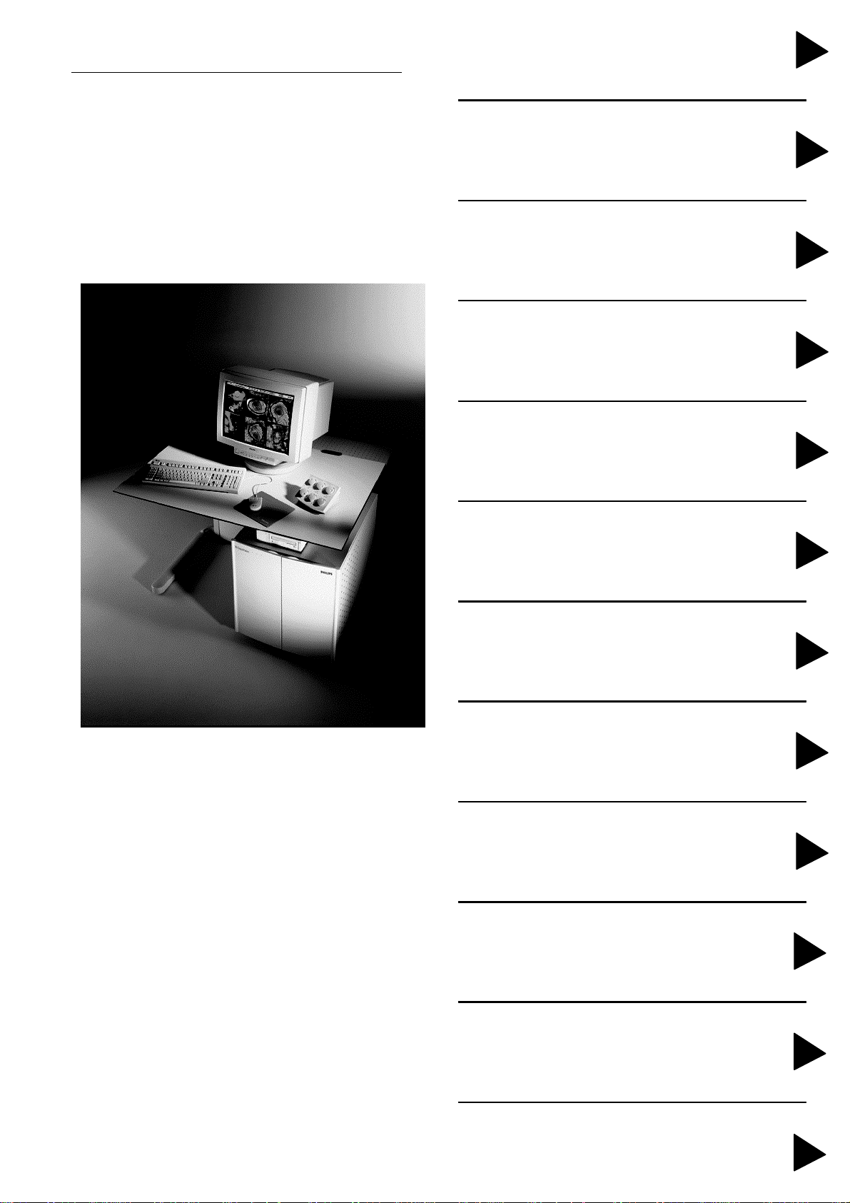
EasyVision RAD release 4.2 is a workstation as well as an acquisition system for PCR Readers. Beside that
the EasyVision RAD serves as an image processing system with printing capabilities. PCR Readers can
connect with both DMS interface and via Ethernet to an EasyVision RAD.
Moreover the EasyVision RAD 4.2 supports multi reader configurations with:
- 1 DMS Reader
- up to 2 network Readers
dependent on the performance of the hardware used.
The Single User Workstation
If there is only one EasyVision connected to one or more readers/USITs, the situation is like that before
release 4.2. To differentiate between such a single EasyVision RAD and those in a cluster configuration, we
call the single system a Single User Workstation.
The EasyServer
Within an EasyVision RAD cluster, the EasyVisions use a common place to store their images. The system
which does this is called the EasyServer. It controls the configuration of the cluster by controlling the
software licenses, it handles the import from modalities, the printing to film, and all communication outside
the cluster, for instance with the archive, external DICOM databases, or other clusters and workstations of
other vendors.
The Workspot (Client)
The EasyServer makes all images available to all EasyVisions in the cluster. The EasyVisions which also
run the RAD applications (the Workspots) don’t have an own image database and use the image database
of the RAD server. The hardware configuration of the Workspot may vary from an UltraSparc 60 with lots of
memory for fast and intensive image postprocessing, to a PC with a Java enabled Web Browser for basic
image viewing.
1.1. D
OCUMENTATION STRUCTURE
Delivered with the system
- System Manual EasyVision RAD 4.2
- Network Manual
- Printer Compatibility
Delivered with the software
- Release Bulletin EasyVision RAD 4.2 Level n
- DICOM Conformance Statement
Delivered with the Sun workstation
- Unit Manual EasyVision RAD Sun Ultra or SunBlade
Delivered with the monitor
- Unit Manual Monitor
EasyVision RAD R4 (a/03.1) 1-3
Copyright © 1999-2003 Philips Medical Systems
ALL RIGHTS RESERVED
Page 7
Section 1 Introduction And Technical Data
1.2. T
EasyVision RAD system are mostly sold as part of a PCR system treating the special needs of CR images.
Data can be imported from other modalities or other workstations as well.
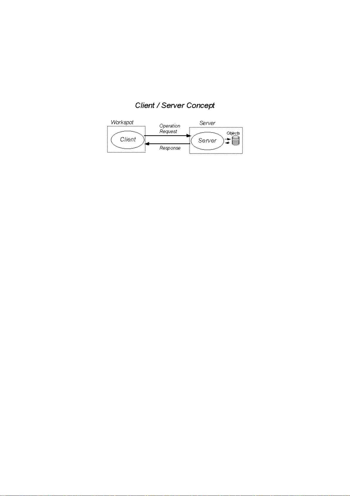
EasyVision Release 4 is based on a client/server computing technology. This means a different configuration
will appear: Users on a workspot use information that resides in a database on a central server and is
received from a larger variety of sources.
ECHNOLOGY
1.3. T
To remove and replace EasyVision field replaceable units (FRUs), you will need the following tools and
materials:
• Standard toolkit
• Anti-static discharge kit
• Service network hub 10/100Mbit
• Service PC + null modem cable (25pin) for back-up of configuration files.
See Remote Service Manual for pin layout)
• Densitometer for laserprinter (e.g. X-Rite 331)
• Reflection densitometer for paperprinter (e.g. X-Rite 400)
• Hardcopy Unit test box
• Printer test tool
• Multimeter.
OOLS
1-4 (a/03.1) EasyVision RAD R4
Copyright © 1999-2003 Philips Medical Systems
ALL RIGHTS RESERVED
Page 8
Introduction And Technical Data Section 1
2. PRODUCT DATA
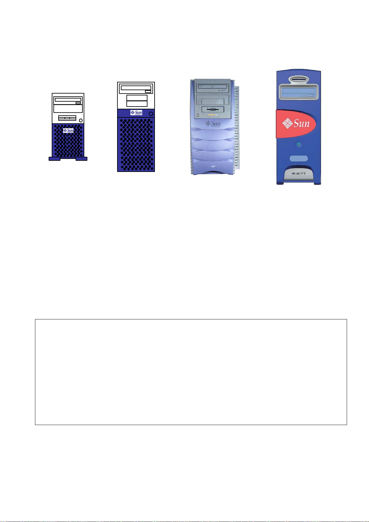
2.1. C
OMPUTERS
Ultra 10 Ultra 60 SunBlade 1000 Sun Blade 1500
Ultra 10: The Sun Ultra 10 is a single processor PCI based workstation/server using the UltraSPARC-
II 64-bit architecture. The system has a PC style mini-tower layout.
Ultra 60: The Sun Ultra 60 is PCI based workstation using the UltraSPARC-II 64-bit architecture. The
system has a PC style mini-tower layout and is functionally equivalent to the Sbus based
Ultra 2 workstation.
SunBlade
1000/ 2000:
The Sun Blade 1000/2000 workstation is a dual processor workstation that uses the
UltraSPARC III family of processors. The workstation offers super-scalar processor
technology, multiprocessing, high-performance memory interconnection, highbandwidth
input/output (I/O), and accelerated graphics.
SunBlade
1500
The Sun Blade 1500 workstation is a single processor workstation that uses the
UltraSPARC IIIi family of processors.
2.2. O
VERVIEW CONFIGURATION
Ultra 10 Ultra 60 SunBlade 1000/2000 SunBlade 1500
onboard SCSI-interface
IDE-interface
Ethernet interface
Min memory
Max. memory (MB)
Memory module
Memory bank config.
Internal disk
CD-ROM /DVD-ROM
PCI slots
Framebuffers
no Ultra SCSI, 40 MB/s Ultra Wide SCSI no
EIDE, 33 MB/s No No UltraDMA100
10/100 Mbit 10/100 Mbit 10/100 Mbit 10/100/1000BASE-T
256MB (2x128 MB) 256MB (4x64MB) 512MB (4x128MB) 512MB (4x128MB)
384-/512-/768 512-/ 768-/ 1024
768-/ 1280- / 1792
64- / 128- / 256 MB 64- / 128 MB 128-/256-/1024 MB 128 MB - 2GB
2 banks x 2 slots 4 banks x 4 slots 8 DIMM slots 4 slots
EIDE, 9.1 GB Ultra-SCSI, 9.1 GB UW-SCSI 2x 36GB 1x 80 GB IDE
CD-ROM EIDE, 24x CD-ROM SCSI DVD-ROM SCSI DVD-ROM IDE
4 4 4 5
Yes, 8 bit No No No
up to 8GB up to 8GB
(system disk)
1x 36GB SCSI
(image disk)
EasyVision RAD R4 (a/03.1) 1-5
Copyright © 1999-2003 Philips Medical Systems
ALL RIGHTS RESERVED
Page 9

Section 1 Introduction And Technical Data
2.3. F
RAMEBUFFERS
PseudoColor PGX
(+)
Color Greyscale
Pseudo Color
PCI/PGX
(+)
TrueColor
UPA/FFB
Ultra 10 (4xPCI + 1x UPA) Onboard* 3x 1x 2x
Ultra 60 (4xPCI + 2x UPA) No No 2x 2x
SunBlade 1000/2000
No No 2x 2x
(4xPCI + 2x UPA)
SunBlade 1500: XVR 500 or XVR100
• The Ultra 10 has an onboard framebuffer which cannot be removed.
• EasyVision cannot handle a mix of different types of framebuffers.
2.4. M
ONITORS
Display matrix: 1280 x 1024 Landscape oriented
Framebuffer type
Pseudo Color PGX
(+)
single head Yes Yes Yes,
18" Color 21" Color 21" Greyscale
Color Monitors Greyscale monitors
True Color (FFB) single head Yes Yes Yes,
Greyscale (Md2) dual head No No Yes
2.5. O
PTICAL MEDIA DRIVES
MD2/PCI
EasyStore OD Drive EasyStore CD-R drive
Pioneer DE-UH710 600MB (obsolete) Standard CD-R drive
2.6. M
EMORY BANK CONFIGURATIONS
Ultra 10
Slot 1 Slot 2
Bank 1 128 128
Bank 2 128/256 128/256
Ultra 60
Slot 1 Slot 2 Slot 3 Slot 4
Bank 1 32 32 32 32
Bank 2 32 32 32 32
Bank 3 64/128 64/128 64/128 64/128
Bank 4 64/128 64/128 64/128 64/128
SunBlade 1500
SDRAM
Organization
Number of
DRAMs
Physical bank
per DIMM
Module
Configuration
DIMM
Capacity
Minimal
Memory
Maximum
Memory
128Mbit (32Mx4) 18 1 32Mx72 256MB 512MB 1GB
128Mbit (16Mx8) 18 2 2x(16Mx72) 256MB 512MB 1GB
256Mbit (32Mx8) 9 1 32Mx72 256MB 512MB 1GB
256Mbit (64Mx4) 18 1 64Mx72 512MB 1GB 2GB
256Mbit (32Mx8) 18 2 2x(32Mx72) 512MB 1GB 2GB
512Mbit (64Mx8) 9 1 64Mx72 512MB 1GB 2GB
512Mbit (128Mx4) 18 1 128Mx72 1GB 2GB 4GB
512Mbit (64Mx8) 18 2 2x(64Mx72) 1GB 2GB 4GB
1Gbit (256Mx4) 18 1 256Mx72 2GB 4GB 8GB
1Gbit (128Mx8) 18 2 2x(128Mx72) 2GB 4GB 8GB
1-6 (a/03.1) EasyVision RAD R4
Copyright © 1999-2003 Philips Medical Systems
ALL RIGHTS RESERVED
Page 10

Introduction And Technical Data Section 1
2.7. C
ONNECTIVITY
Connectivity
SCSI parallel
(DMS)
parallel
3M
parallel
printer
Ethernet
Interf.
USIT x
AC500/5000 x
PCR Preview Unit x
AC3/3000 PCR9000 (DMS) X
Printers 3M Interf. X
Printers DICOM x
Printers SCSI X
Printers PostScript X
EasyVision RAD R4 (a/03.1) 1-7
Copyright © 1999-2003 Philips Medical Systems
ALL RIGHTS RESERVED
Page 11
Section 1 Introduction And Technical Data
r
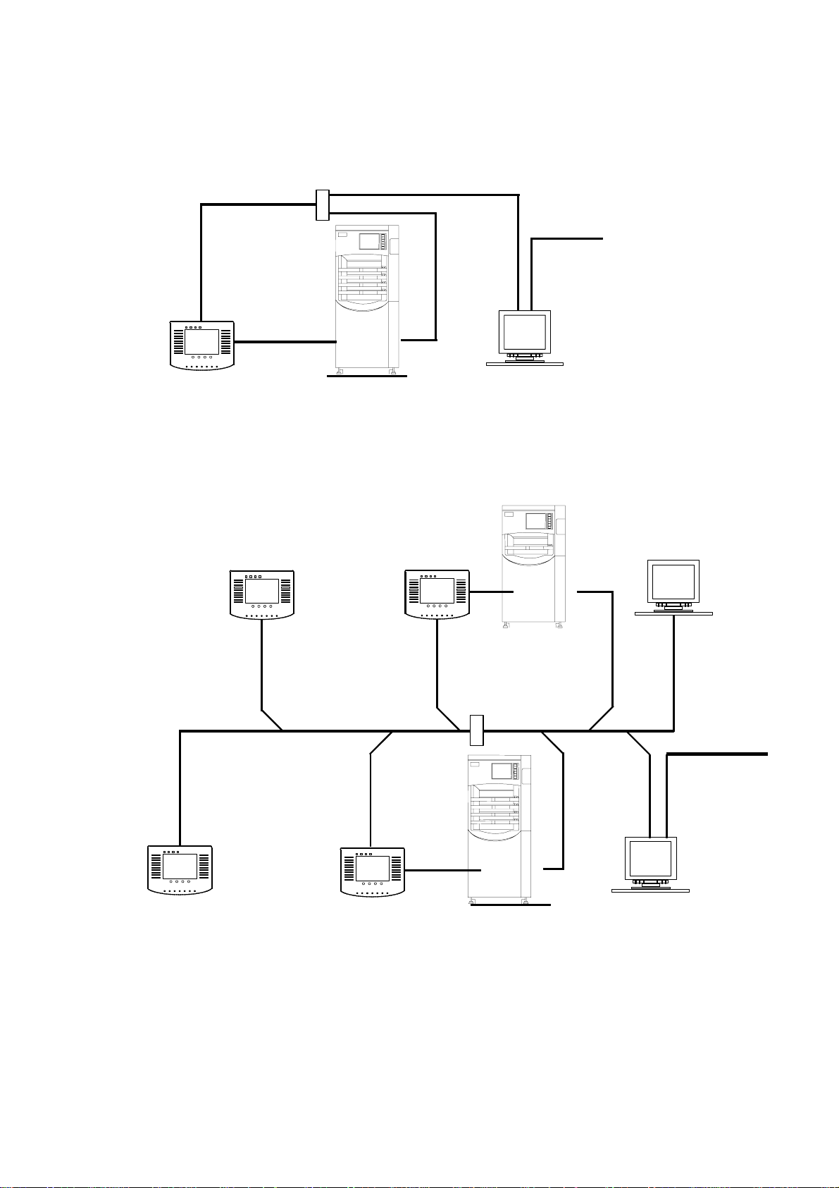
3. EASYVISION RAD CONFIGURATIONS
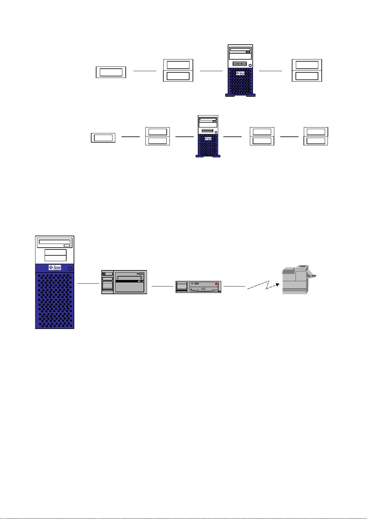
3.1. PCR
STANDALONE CONFIGURATION
hub
Fast Ethernet rec.
Local o
DICOM print
Server USIT EasyVision
Reader
IDT
Terminal Name : USIT 1
Terminal IP Address : 192.0.0.2
EV rad Names : EV 1
EV rad IP Adresse : 192.0.0.1
Display : EV1
Hosts : 192.0.0.1 EV1
192.0.0.3 AC 5000F
192.0.0.4 AC 5000E
IP Name : EV 1
IP Address : 192.0.0.1
3.2. PCR M
ULTI READER CONFIGURATION
Client USIT Reader USIT Reader
IDT
EasyVision
(Work spot)
Server Name : USIT 1
Server IP Address : 192.0.0.2
Terminal Name : USIT 3
Terminal IP Address : 192.0.0.4
EV rad Name : EV 1
EV rad IP Address : 192.0.0.1
Client USIT
Server Name : USIT 1
Server IP Address : 192.0.0.2
Terminal Name : USIT 2
Terminal IP Address : 192.0.0.3
EV rad Name : EV 1
EV rad IP Address : 192.0.0.1
Server Name : USIT 1
Server IP Address : 192.0.0.2
Terminal Name : USIT 4
Terminal IP Address : 192.0.0.5
EV rad Name : EV1
EV rad IP Address : 192.0.0.1
Display : EV1
Hosts : 192.0.0.1 EV1
192.0.0. 9 AC 500F-B
192.0.0.10 AC 500E-B
IP Name : EV 2
IP Address : 192.0.0.6
hub
Ethernet
Server USIT
Fast Ethernet
Hospital
Network
Reader
EasyVision
(server)
IDT
IP Name : EV 1
Terminal Name : USIT 1
Terminal IP Address : 192.0.0.2
EV rad Name : EV 1
EV rad IP Address : 192.0.0.1
Display : EV1
Hosts : 192.0.0.1 EV1
192.0.0.7 AC 5000F- A
192.0.0.8 AC 5000E- A
IP Address : 192.0.0.1
Remark:
Hostnames and IP Addresses are
examples and should be adapted to
the network
1-8 (a/03.1) EasyVision RAD R4
Copyright © 1999-2003 Philips Medical Systems
ALL RIGHTS RESERVED
Page 12

Introduction And Technical Data Section 1
4. NETWORK CONNECTIONS
Building blocks to build a network, like hubs, switches and other related parts, are NOT part of the
EasyVision delivery. These parts have to be purchased locally.
4.1. C
In this cluster concept two networks are determined. Network connection via Base-T Ethernet.
LIENT SERVER CLUSTERS
EasyVision RAD R4 (a/03.1) 1-9
Copyright © 1999-2003 Philips Medical Systems
ALL RIGHTS RESERVED
Page 13

Installation Section 2
Section 2 Installation
1.
2.
3.
4.
Contents
WHAT IS DELIVERED ........................................................................................................................... 3
TIME AND PERSONNEL NEEDED .......................................................................................................3
PHYSICAL INSTALLATION .................................................................................................................. 3
CABLING................................................................................................................................................ 4
4.1. SunBlade 1500........................................................................................................................................ 4
4.2. Ultra 10 / 60, SunBlade 1000 / 2000....................................................................................................... 5
4.3. Client / server network connection.......................................................................................................... 6
4.4. Ethernet Loopback Connector ................................................................................................................ 7
4.5. Laser Hardcopy Unit (point-to-point)....................................................................................................... 7
4.6. Mains Cables .......................................................................................................................................... 7
4.7. Cable Relief............................................................................................................................................. 7
5.
PERIPHERAL CABINETS...................................................................................................................... 8
5.1. SCSI-chain configurations ...................................................................................................................... 8
5.1.1. ULTRA 10 PTI 2 Configurations.......................................................................................................... 8
5.1.2. ULTRA 10 PTI 2 + PTI 1 Configurations ............................................................................................. 9
5.2. ULTRA 60 PTI 2 + PTI 1 Configuration ................................................................................................ 10
5.2.1. Onboard SCSI only............................................................................................................................ 10
5.2.2. Onboard SCSI and Twin SCSI card .................................................................................................. 10
5.3. SunBlade Configuration ........................................................................................................................ 11
6.
CONNECTING A PRINTER ................................................................................................................. 12
6.1. HardCopy Unit....................................................................................................................................... 12
6.2. SCSI Printer .......................................................................................................................................... 12
6.3. Network Printer ..................................................................................................................................... 12
6.4. Parallel Printer....................................................................................................................................... 12
7.
ADDING PERIPHERALS TO PERIPHERAL ENCLOSURE ............................................................... 13
8.
CONNECTIVITY ................................................................................................................................... 13
8.1. Printers .................................................................................................................................................. 13
8.2. NetView ................................................................................................................................................. 13
8.3. DICOM .................................................................................................................................................. 13
EasyVision RAD R4 (a/03.1) 2- 1
Copyright © 2003 Philips Medical Systems
ALL RIGHTS RESERVED
Page 14

Section 2 Installation
2-2 (a/03.1) EasyVision RAD R4
Copyright © 1999-2003 Philips Medical Systems
ALL RIGHTS RESERVED
Page 15

Installation Section 2
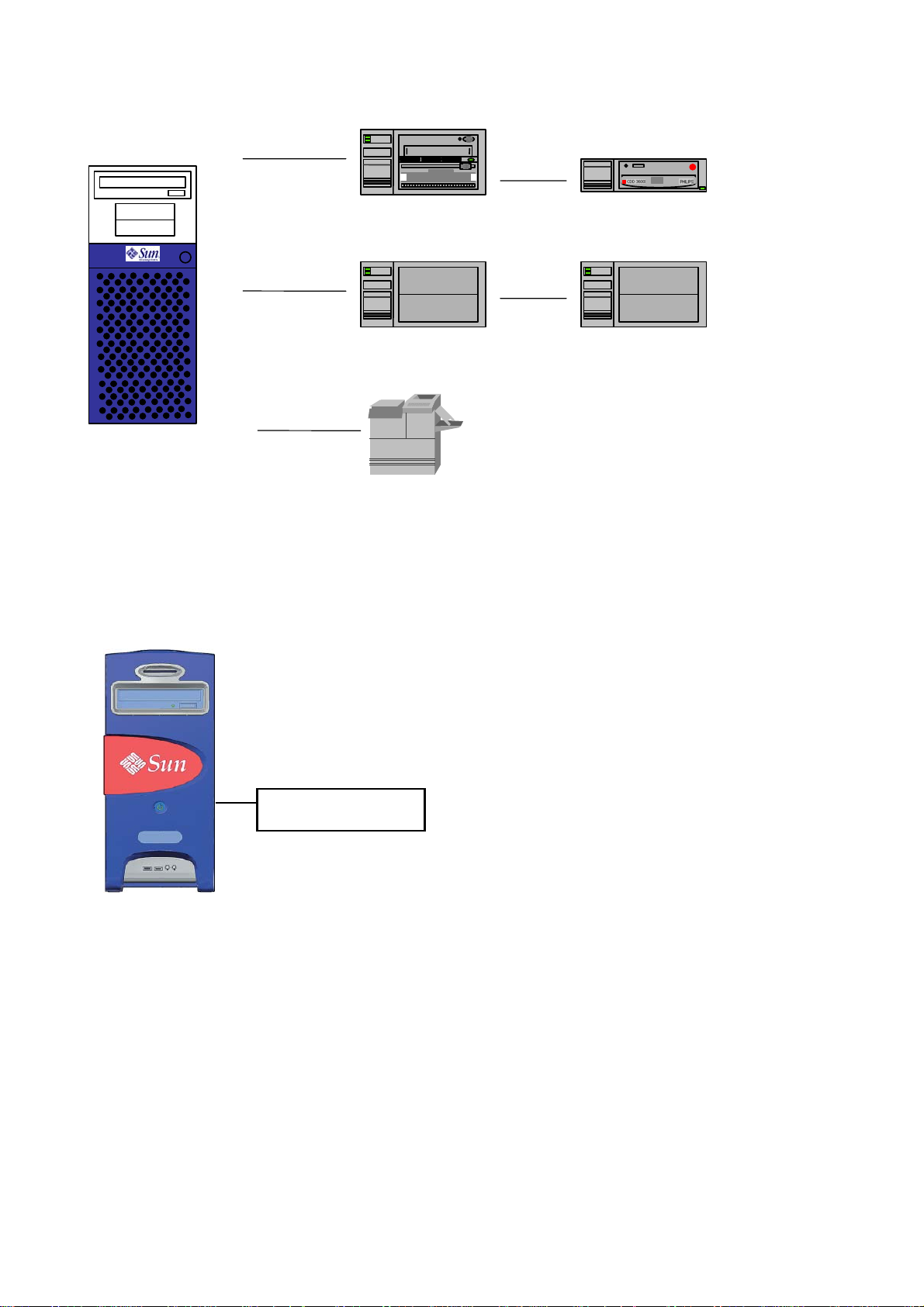
1. WHAT IS DELIVERED
Ultra 10 / 60 / SunBlade
Memory
(Onboard) framebuffer
Keyboard + mouse
DVD /CD-ROM drive
Monitors
LCD: Color 18"
Peripherals
EasyStore (Optical Disc) PTI 2 (obsolete)
EasyStore (CD-R) PTI 1
Optional
Hardcopy unit board
Ethernet card (Quad / Single)
Dome Md2 greyscale framebuffer for 2 monitors
Creator card (True color)
Twin SCSI Card
The main part of this section describes the hardware installation per system. This can be a standalone
EasyVision, a Server or a Workspot! Look at the commercial order what is appropriate for your environment.
For a client/server environment installation, see chapter 4.3 Client / server.
Internal hard drive
CRT: Color 17", 21"; greyscale 21"
Image disks PTI 2
Memory Extension
2. TIME AND PERSONNEL NEEDED
The total installation can be done by just one person.
The total installation of a stand-alone EasyVision can be done within eight hours. Even the installation of a
small network can be completed within 8 hours.
3. PHYSICAL INSTALLATION
The software has been installed at the factory. The software installation keeps track of the SCSI chain
configuration. For this reason it is very important to build the same hardware configuration as assembled in
the factory. The SCSI chains on the SUN and corresponding peripheral cabinets are labeled with stickers
(SCSI-A, SCSI-B or SCSI-C).
If the SCSI chain changes for any reason (e.g. an option) the OS and AS software must be reinstalled!
There are no transport lockings.
• All components of the system should be placed on a table.
Do not place the system on the floor to avoid damage (kicking the system with feet, water (cleaning
personnel), dust and dirt etc.).
• Place peripheral cabinet(s) next to the Sun workstation.
• Place keyboard within reach on the table.
• Place mouse + mouse pad within reach on the table.
• Place the mains distribution unit within reach on the table. The mains distribution unit contains the
system power on/off switch.
EasyVision RAD R4 (a/03.1) 2- 3
Copyright © 2003 Philips Medical Systems
ALL RIGHTS RESERVED
Page 16
Section 2 Installation
4. CABLING
NOTE
Check all external and internal interface cables (e.g., the SCSI cable to the image hard disk, CD-ROM), as
they may have moved during transport.
________________
• Connect the video cable from the monitor to the workstation's video connector.
• Connect the monitor power cable to the power distribution unit.
• Connect keyboard and mouse.
• Network kit or cable must be obtained locally. EasyVision can be connected to the network via a twisted
pair (TP) connection.
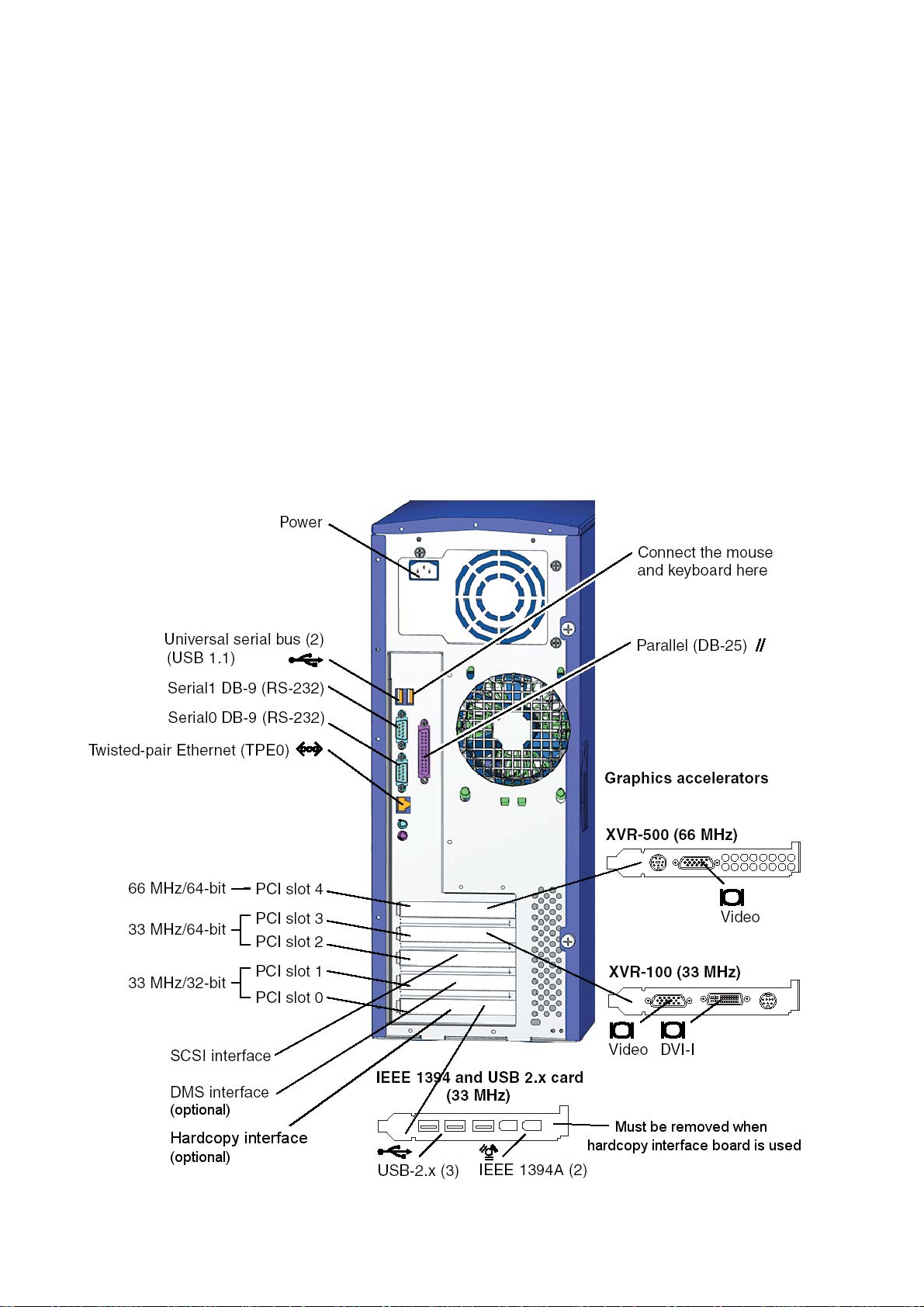
4.1. SUNB
LADE
1500
2-4 (a/03.1) EasyVision RAD R4
Copyright © 1999-2003 Philips Medical Systems
ALL RIGHTS RESERVED
Page 17

Installation Section 2
This figure illustrates the cable connections for the SunBlade 1500 workstation.
4.2. U
LTRA
10 / 60, SUNB
LADE
1000 / 2000
See Z drawings of appropriate Sun workstation for connections.
EasyVision RAD R4 (a/03.1) 2- 5
Copyright © 2003 Philips Medical Systems
ALL RIGHTS RESERVED
Page 18
Section 2 Installation
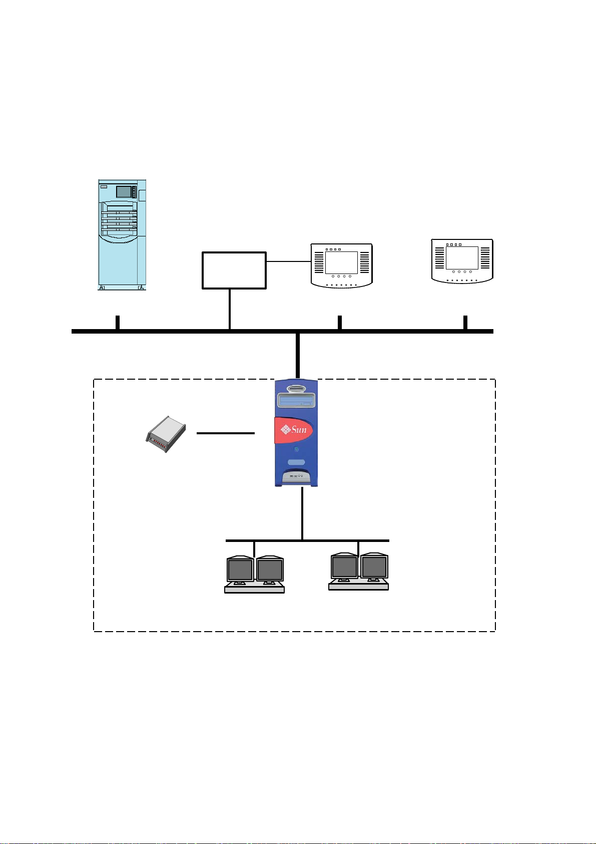
4.3. C
See Z drawings for cable diagrams.
Example:
LIENT / SERVER NETWORK CONNECTION
IDT
PreView
Unit
Reader
EasyVision RAD cluster
Modem
User Terminal
Server
network
Server
EasyVision RAD network
User Terminal
Client
Workspot #1
2-6 (a/03.1) EasyVision RAD R4
Copyright © 1999-2003 Philips Medical Systems
ALL RIGHTS RESERVED
Workspot #n
Page 19

Installation Section 2
4.4. E
The loopback connectors serves two purposes.
• If a network is not connected to EasyVision, connect the loopback connector to the Ethernet connection
at the end of the adaptor cable. This suppresses the UNIX message 'no carrier' (to console).
• Diagnostic purpose in Forth Diagnostics, see Unit Manual.
In case of a Single/Quad Ethernet card: The unused controllers must have an Ethernet loopback connector
4.5. L
Hardcopy units with point-to-point connection are connected to the EasyVision via split cable by a DATA
and CONTROL cable (SUB-D 37p connectors). Connect the Data and Control cables.
Ensure that the correct connections have been made for the DATA and CONTROL cables. Interchanging
Refer to the chapter "Connecting a Printer" in this Section 2.
4.6. M
THERNET LOOPBACK CONNECTOR
________________
ASER HARDCOPY UNIT (POINT-TO-POINT
these cables may destroy the hard copy interface board.
________________
AINS CABLES
NOTE
connected
NOTE
)
Fit the correct mains plug to the mains cable of the power distribution unit provided. A couple of mains plugs
are delivered with the system but if the correct one for your environment is not there, you will have to obtain
one locally.
• Connect the mains cable between the Sun workstation and the power distribution unit.
• Connect the mains cable between the peripheral cabinet(s) and the power distribution unit.
• Connect the mains cable between the monitor and the power distribution unit.
• Connect the mains cable to a mains wall socket.
• The hardcopy unit's power cable may now be connected to the mains supply (if relevant).
NOTE
Make sure that the HCU has been connected to the same mains distribution point as the EasyVision. This is
important to protect both the HCU interface of the EasyVision RAD and the interface of the HCU from
voltage differences dangerous for the electronic interface components.
4.7. C
Relieve the power cable, network cable and hardcopy cables with Ty-Raps or flexible cable wrapper
delivered.
ABLE RELIEF
EasyVision RAD R4 (a/03.1) 2- 7
Copyright © 2003 Philips Medical Systems
ALL RIGHTS RESERVED
Page 20
Section 2 Installation
5. PERIPHERAL CABINETS
Note
The last peripheral cabinet in each SCSI chain must be terminated with a SCSI terminator.
________________
CAUTION
If the SCSI chain configuration has been changed, the OS and application software be re-installed
________________
5.1. SCSI-
Abbreviation Device SCSI
ID(1) Image Disk Wide SCSI (68 pin)
ID(2) Additional Image Disk 1 Wide SCSI (68 pin)
ID(3) Additional Image Disk 2 Wide SCSI (68 pin)
ID(4) Additional Image Disk 3 Wide SCSI (68 pin)
ES EasyStore (DOR) Narrow SCSI (50 pin)
CD-Rec EasyStore (CD-Recorder) Narrow SCSI (50 pin)
70cm
h
n
CHAIN CONFIGURATIONS
h: 68p UHD (Ultra High Density)
n: 68p FW (Fast Wide)
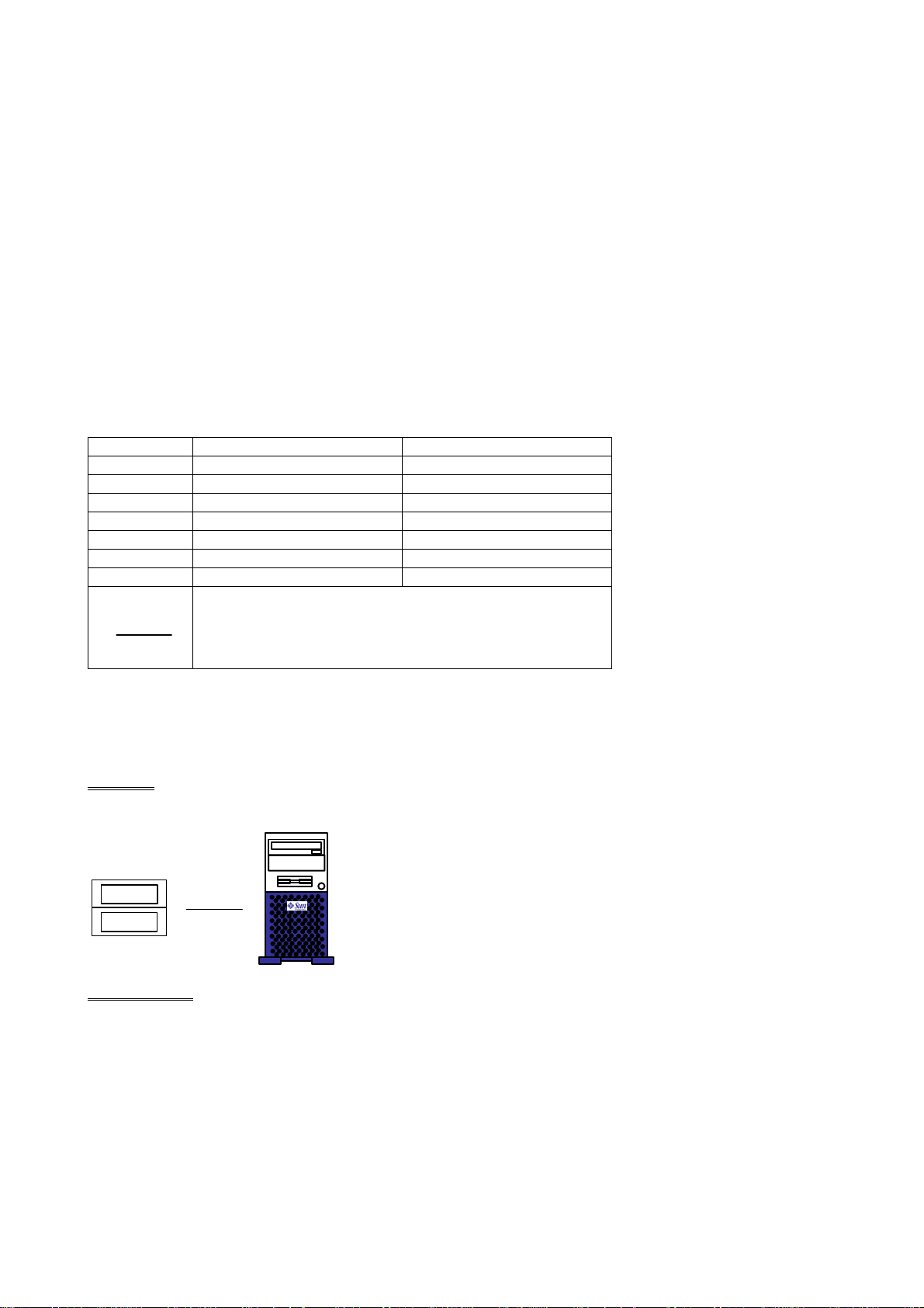
5.1.1. ULTRA 10 PTI 2 C
Desktop:
50cm
70cm
n
h
PTI 2 (1)
Configuration 1
ONFIGURATIONS
ID(1) ID(2) ES
X
X X
X
X X
X
X
PTI 2 (1)
2-8 (a/03.1) EasyVision RAD R4
Copyright © 1999-2003 Philips Medical Systems
ALL RIGHTS RESERVED
Page 21
Installation Section 2
PTI 2 (1) PTI 2 (2)
PTI 2 (1)
70cm
nn
h
70cm
h
Configuration 2
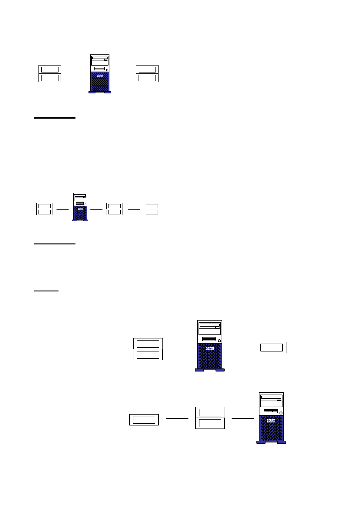
In case of 4 image disks, you may use 1 SCSI chain (See right hand side of configuration 3)
70cm
nn
h
PTI 2 (1)
70cm
hn
PTI 2 (2) PTI 2 (3)
50cm
n
50cm50cm
ES ID(1) ID(2) ID(3) ID(4)
X
X
PTI 2 (2)
NOTE
________________
50cm50cm50cm
X
X
X X
X
X
X X
PTI 2 (1) PTI 2 (2) PTI 2 (3)
ES ID(1) ID(2) ID(3) ID(4)
X X X
X X X X
X X X X X
Configuration 3
5.1.2. ULTRA 10 PTI 2 + PTI 1 C
Desktop:
Configuration 1
+
CD-R
50cm
PTI 2 (1)
Configuration 1
+
CD-R
30cm
ONFIGURATIONS
30cm
70cm
nn
h
150cm
h
PTI 1
50cm
hn
70cm
n
50cm
n
PTI 1
PTI 2 (1)
EasyVision RAD R4 (a/03.1) 2- 9
Copyright © 2003 Philips Medical Systems
ALL RIGHTS RESERVED
Page 22
Section 2 Installation
Configuration 2
+
CD-Rec
30cm
50cm
hn
70cm
70cm
n
h
50cm
nn
50cm
PTI 1
Configuration 3
+
CD-Rec
30cm
PTI 1
50cm
n
5.2. ULTRA 60 PTI 2 + PTI 1 C
5.2.1. O
In case of 3 devices (or less), only the onboard SCSI card is available. The next figure shows the
configuration.
NBOARD
SCSI
PTI 2 (EasyStore + Image Disk)
ONLY
PTI 2 (1)
50cm
hn
PTI 2 (1)
ONFIGURATION
70cm
50cm
70cm
n
h
n
PTI 2 (2)
PTI 2 (2)
50cm
n
Printer
50cm
n
PTI 2 (2)
50cm
nn
Onboard SCSI
5.2.2. O
In case of more than 3 devices, a twin SCSI card is needed. The next figure shows the configuration.
NBOARD
SCSI
AND TWIN
50cm
nn n
SCSI
PTI 1 (CD-Rec)
CARD
15cm
SCSI booster
+ 3m cable
2-10 (a/03.1) EasyVision RAD R4
Copyright © 1999-2003 Philips Medical Systems
ALL RIGHTS RESERVED
Page 23
Installation Section 2
5.3. SUNB
PTI 2 (EasyStore
70 cm
h
Twin SCSI 1
70 cm
h
Twin SCSI 2
< 300 cm
n
Onboard SCSI
LADE CONFIGURATION
n
n
n
PTI 1 (CD-Rec )
50 cm
nn
2x PTI 2 (4x image disk)
50 cm
nn
Printer
A twin SCSI card is built in. The image disk has a internal connection to the SCSI card. A CD-R drive is
connected externally to the SCSI card.
PTI EasyStore CD-R
EasyVision RAD R4 (a/03.1) 2- 11
Copyright © 2003 Philips Medical Systems
ALL RIGHTS RESERVED
Page 24

Section 2 Installation
6. CONNECTING A PRINTER
See Z drawings for connection possibilities.
6.1. H
In the service manual Imager Compatibility you will find a compatibility list of the hardcopy units supported
by the EasyVision. Furthermore you will find the settings for the various hardcopy units, when connected to
EasyVision. Usually the HCU service engineer will configure the HCU and will have the information
necessary to do this. In some cases however he may not be aware of special settings when connecting to
EasyVision.
6.2. SCSI P
Note: The maximum length of a SCSI chain, including the printer SCSI cable, is 3 meters !!!
See Z drawings.
To connect an SCSI Printer, remove the SCSI terminator from the peripheral enclosure.
Connect the printer SCSI-cable and SCSI adapter narrow/narrow between the SCSI connector of the
peripheral enclosure and the printer itself or if relevant to a SCSI booster.
Put the SCSI terminator on the second SCSI connector of the printer or in case of a SCSI booster the
termination is done by the SCSI extender (so no external terminator required).
For detailed installation information of SCSI printers please refer to the installation manual delivered with the
printer.
6.3. N
ARDCOPY UNIT
RINTER
ETWORK PRINTER
The network printer is connected to the network.
6.4. P
A PostScript printer can be connected to the parallel port (max. length - 3m).
ARALLEL PRINTER
2-12 (a/03.1) EasyVision RAD R4
Copyright © 1999-2003 Philips Medical Systems
ALL RIGHTS RESERVED
Page 25

Setting to Work Section 3
Section 3 Setting to Work
Contents
1.
2.
2.1.
2.2.
2.3.
3.
3.1.
3.2.
3.3.
4.
5.
5.1.
5.2.
5.3.
5.3.1. Verification of the Density Calibration ................................................................................................. 9
5.4.
INTRODUCTION ................................................................................................................................. 3
POWER ON......................................................................................................................................... 3
Power On Self Test and OpenBoot PROM phases ............................................................................ 3
Start-up Menu...................................................................................................................................... 3
Configuration / Customization ............................................................................................................. 3
POWER OFF....................................................................................................................................... 4
Power-off in Application Mode............................................................................................................. 4
Power-off in Service Mode .................................................................................................................. 4
When the System Does Not Respond Normally ................................................................................. 4
MONITOR ADJUSTMENT.................................................................................................................. 5
HARD COPY UNIT CALIBRATION.................................................................................................... 5
Introduction.......................................................................................................................................... 5
Preconditions....................................................................................................................................... 5
HCU Density Calibration ..................................................................................................................... 5
Pixel Size calibration ......................................................................................................................... 10
5.5.
6.
Checking the Results ........................................................................................................................ 11
EASYVISION RAD / HCU CALIBRATION FORM ........................................................................... 13
EasyVision RAD R4 (a/03.1) 3-1
Copyright © 2003 Philips Medical Systems
ALL RIGHTS RESERVED
Page 26

Section 3 Setting to Work
3-2 (a/03.1) EasyVision RAD R4
Copyright © 2003 Philips Medical Systems
ALL RIGHTS RESERVED
Page 27

Setting to Work Section 3
1. INTRODUCTION
The operating system, application software and license file are factory installed. For software configuration
and customization see Release Bulletin.
2. POWER ON
Check if the mains switch of the Sun computer and its peripheral devices are in the ON position.
Switch on the complete system by switching on the switch of the power distribution box. The light on the
mains switch box is always on when power is applied to it.
2.1. P
After power on the factory-defined Power On Self Test (POST) phase and the OpenBoot PROM phase are
performed automatically (see also chapter "Sun Troubleshooting Overview", paragraphs "Factory Defined
Boot Mode" and "After Power Is Switched On").
POST phase
During the POST phase the blinking Caps Lock LED on the keyboard will tell you the POST is in progress.
At successful completion of the POST phase the OpenBoot PROM firmware takes control.
OpenBoot PROM phase
During the OpenBoot PROM phase (high level POST) you will first see "Testing Memory" on the screen. If
the OpenBoot PROM phase passes error free the system will boot automatically. If an error occurs, a
message on the screen will appear telling you which unit failed.
Now the system should boot, as the SunOS and Application Software has already been loaded at the
factory.
2.2. S
OWER ON SELF TEST AND OPENBOOT
TART-UP MENU
PROM
PHASES
After boot up the system will display the Start- up Menu. If no selection (number + <Enter>) is made within
10sec, automatically the Application will be started!
1. Start Application
2. Start Customizing
3. Go to Service Menu
4. Go to Installation/Configuration Menu
0. Shutdown
Select item 4 to start the configuration program.
2.3. C
Regarding configuration please refer to the Release Bulletin EasyVision RAD Release 4.2.chapter
configuration.
Regarding customization refer to the instructions for use of the EasyVision RAD.
ONFIGURATION
/ C
USTOMIZATION
EasyVision RAD R4 (a/03.1) 3-3
Copyright © 2003 Philips Medical Systems
ALL RIGHTS RESERVED
Page 28

Section 3 Setting to Work
3. POWER OFF
3.1. P
Client/Server environment: If you turn the EasyServer off, the database is no longer accessible for the
Before switching off the power exit the application as follows:
1. Click
2. Click
3. Click [Confirm].
4. From the start-up menu select 0 Shutdown.
5. When shutdown has completed indicated by the OK prompt switch off the power.
3.2. P
OWER-OFF IN APPLICATION MODE
________________
.
.
OWER-OFF IN SERVICE MODE
NOTE
clients.
1. Exit service mode.
2. From the start-up menu select 0 Shutdown.
3. When shutdown has completed indicated by the OK prompt switch off the power.
3.3. W
To halt a system that is hung, or frozen, and unresponsive to commands:
1. Press <Stop>+<A>.
2. When the ok prompt appears, boot the operating system by entering boot.
3. The system should start up normally.
If the system does not respond to the mouse and keyboard, pressing <Stop>+<A> will not be effective. You
may have to switch the power off, wait at least 10 seconds, and switch the power back on again. Then try
HEN THE SYSTEM DOES NOT RESPOND NORMALLY
NOTE
pressing <Stop>+<A> once more.
________________
3-4 (a/03.1) EasyVision RAD R4
Copyright © 2003 Philips Medical Systems
ALL RIGHTS RESERVED
Page 29

Setting to Work Section 3
4. MONITOR ADJUSTMENT
The brightness and contrast settings are not factory set. To adjust the settings the monitor must be switched
on for at least 30 minutes. Please refer to the Instructions For Use of the EasyVision RAD for how to adjust
the monitor(s).
Should two monitors be placed next to each other pay particular attention to the fact that brightness
perception may differ, depending on the position with respect to the monitor. You must sit in the central
position to verify if there is equal brightness.
NOTE
When you configured EasyVision you should have selected "Normal" for the Monitor correction. (see
Release Bulletin chapter: Configuration). The other selections (Dark and Bright) are only necessary if this
procedure does not give the correct results.
________________
5. HARD COPY UNIT CALIBRATION
5.1. I
After the system has been configured and customized, the correct density calibration (gamma correction
curve) and the pixel size calibration must be carried out on the EasyVision.
The HCU calibration is necessary to establish a correction (curve) between the EasyVision RAD and a
printer (HCU). This correction adapts the EasyVision printing chracteristics to individual deviations of the
printer chracteristics such as laser power adjustment, film chracteristics, developer chemistry or temperature
etc.
The HCU calibration is done in two major steps:
1. The density calibration (Gamma Correction) with HCU calibration and verification of it
2. The pixel size calibration
Note: Both the density calibration and pixel calibration have to be carried out for all media of all printers
connected.
5.2. P
The hard copy unit is setup properly with respect to its configuration (this has to be done by the printer
manufacturers service engineer)
The printers self-calibration has been checked or corrected (manufacturers service engineer or hospital
personnel)
The densitometer has been calibrated and is operating correctly (Philips service personnel)
5.3. HCU D
NTRODUCTION
RECONDITIONS
ENSITY CALIBRATION
In order to use only the test image PrinterCalibration in its original unmodified condition all testimages must
be deleted and then loaded again.
1. Start the application
2. Click
EasyVision RAD R4 (a/03.1) 3-5
.
.
Copyright © 2003 Philips Medical Systems
ALL RIGHTS RESERVED
Page 30
Section 3 Setting to Work
3. Click .
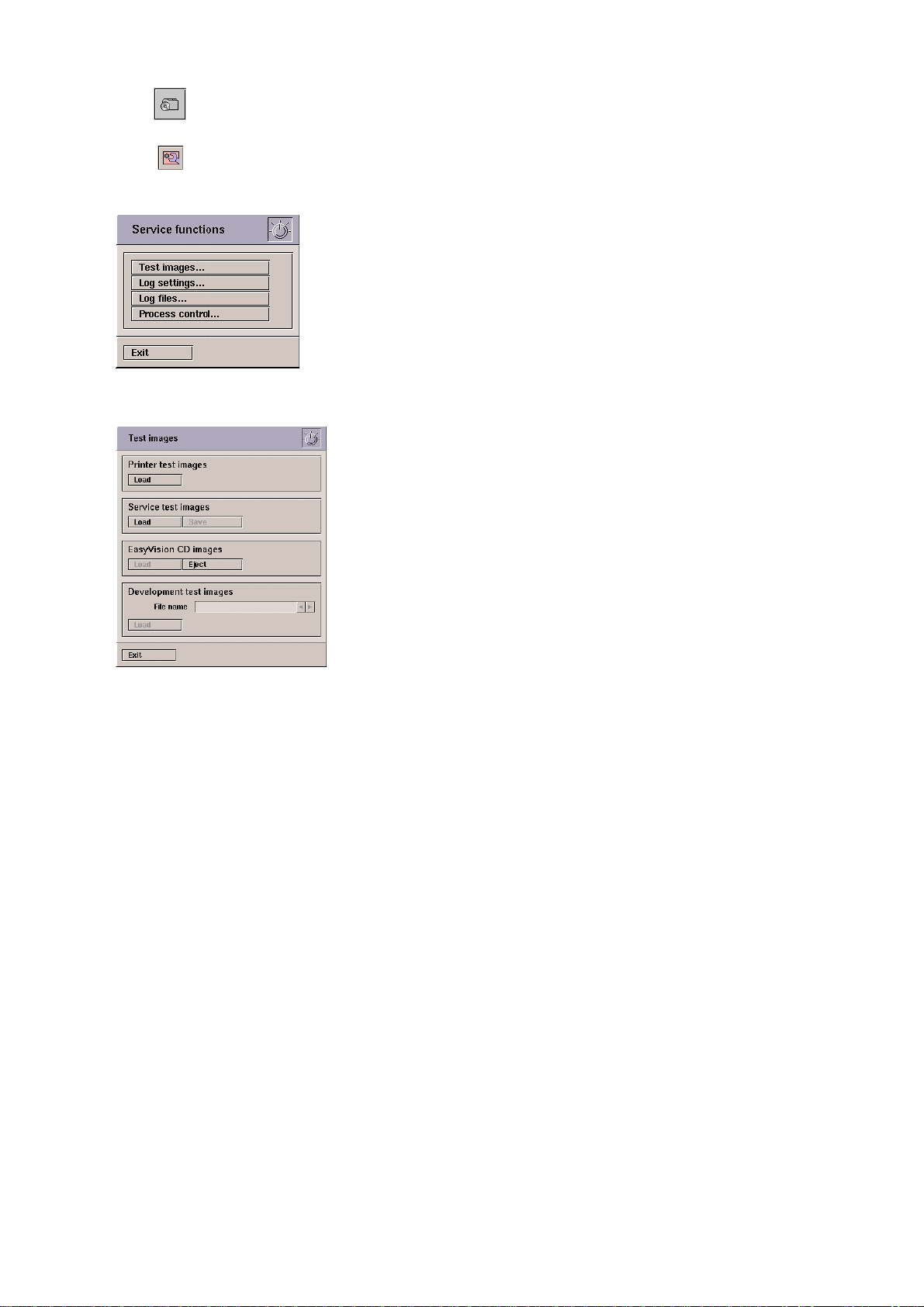
4. Click
.
5. The Service functions window is displayed:
6. Click [Test images]. The Test images window is displayed.
7. In the area Printer test images click [Load]. 23 test images are loaded into the database.
8. Click [Exit].
9. Exit the application and go to Service Menu.
10. Select 4. Printer Menu:
Service Menu
1. Diagnostics Menu (sunvts and product diagnostics)
2. Sun OS Menu (optical disk format and Sun Os commands)
3. File Menu (file transfer and manipulation commands)
4. Printer Menu (printer tests)
5. Monitor Menu (Monitor test images and adjustment)
6. PCR Systems (PCR diagnostics menu)
11. Select 1 HCU Calibration:
Printer Menu
1 HCU Calibration (start hardcopy unit calibration)
2 Start Printer Status Request
3 Start Data Channel Printer Test
4 Start Printer Test
5 Start S-bus/PCI Printer Visual Interface Test
0 Return to Service Menu
The Hard Copy Unit start screen is displayed. HCU Gamma correction and pixel correction must be
carried out for all configured printers and media sizes.
3-6 (a/03.1) EasyVision RAD R4
Copyright © 2003 Philips Medical Systems
ALL RIGHTS RESERVED
Page 31

Setting to Work Section 3
12. Right-click on the printer select spiral icon and select the printer you want to calibrate:
Note: The printer identification strings such as dicom_0_de25sj in the example above tells you that
this is the DICOM printer No. 0 (the first) connected to the EasyVision RAD with the IP node name
de25sj. The relation about which identification string belongs to which physical printer must be
taken from the file /easydata/configuredPrinters.dat at the EasyVision RAD with the node name
de25sj (in this example).
13. Click
to open the hardcopy gamma correction window.
14. Right-click on the spiral icon Media and select the media in the hardcopy unit you want to calibrate the
printer for.
EasyVision RAD R4 (a/03.1) 3-7
Copyright © 2003 Philips Medical Systems
ALL RIGHTS RESERVED
Page 32
Section 3 Setting to Work
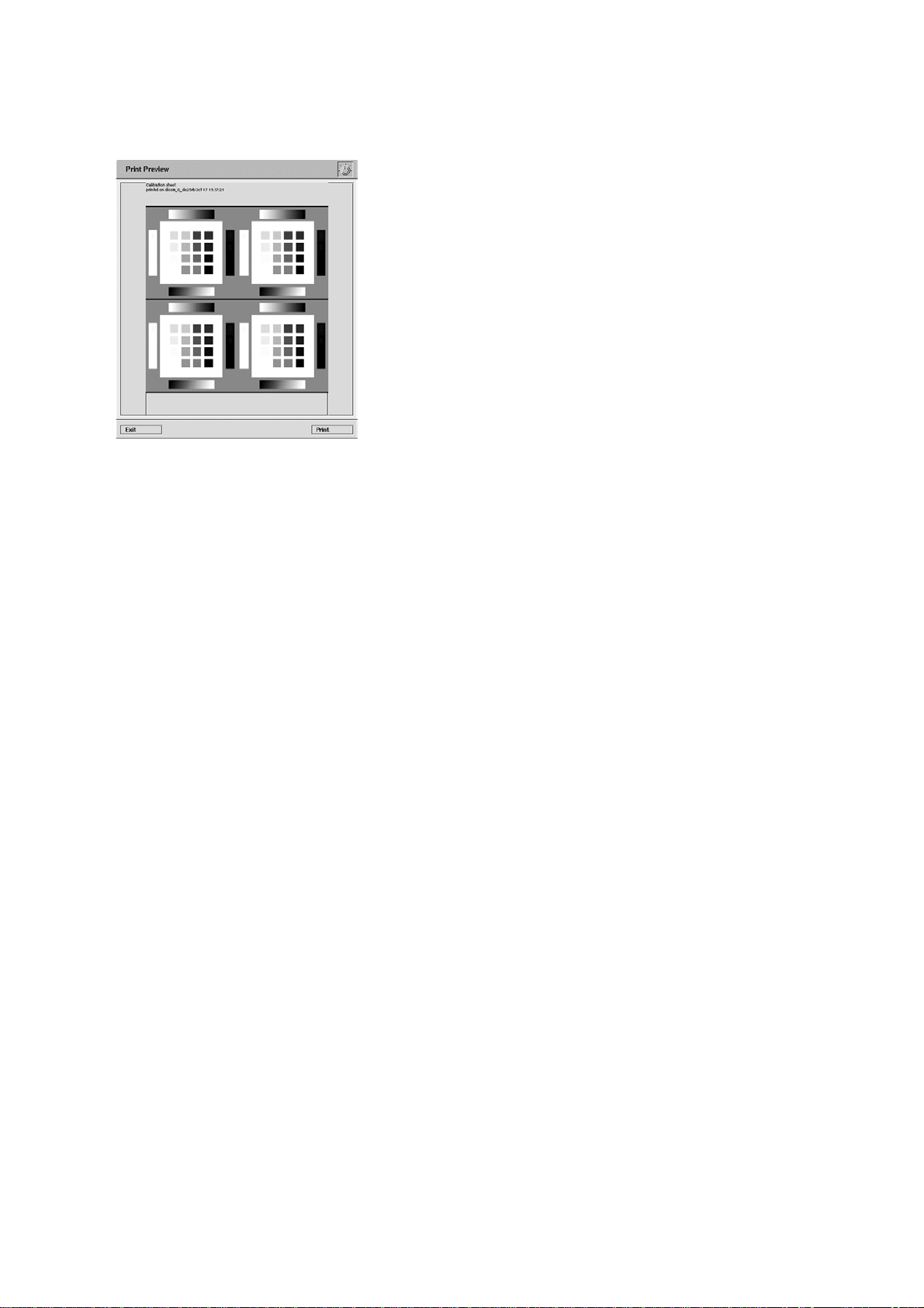
15. Click [Print Calibrate].
13
12
4 5
11
6
14
3
7
2
10
15
1
8
16
9
16. Click [Print]. Wait until the Printing Active panel disappears to indicate that printing is complete.
17. Click [Exit].
18. Measure the density of the 16 grey squares in all 4 arrays.
Start with the darkest grey level: No.1 (Calibrate the densitometer first!)
It is important to measure all 4 arrays (4 times 16 density values = 64 density values). This is
necessary because of the tolerances between the darkest and the lightest areas on the film.
The maximum density must be between 2.9 and 3.1 optical density.
Fill in all measured density values in the Imager Calibration Form at the end of this chapter. Start
with the table EasyVision RAD calibration and fill in the 16 values of an array of 16 squares in one
column e.g. upper left upper right etc. (Don’t use the original form make copies of it for spare).
The result will be all 4 density numbers of all matching grey levels in one row.
Take the 4 readings belonging to one grey level (1 row) calculate the average and enter the result in
the column average of that grey level. Repeat this for all 16 grey levels.
Enter the 16 averages in the row 'Measured density' in the Hard Copy Gamma Correction screen
on the EasyVision; use the TAB key to always select the nearest field on the right
Check whether Application default Standard has been selected.
3-8 (a/03.1) EasyVision RAD R4
Copyright © 2003 Philips Medical Systems
ALL RIGHTS RESERVED
Page 33

Setting to Work Section 3
Click [Save].
Select Specific. Only that media type will be calibrated which is displayed under Media at the top left
of the Hard Copy Gamma Correction panel.
All: in which the calibration is valid for all media types for the printer selected
Matching: in which the calibration is valid for all media of the same size of the printer selected
Click [Save].
Click [Exit] to terminate the Hard Copy Gamma Correction.
5.3.1. V
ERIFICATION OF THE DENSITY CALIBRATION
Checking the results of the Hard Copy calibration, proceed as follows.
1. Make sure the same printer has been selected as in the calibration procedure.
2. Right-click the printer select spiral icon
and select the printer you want to check.
Note: The printer identification strings such as dicom_0_de25rb in the example above tells you: this is
the DICOM printer No. 0 (the first) connected to the EasyVision RAD with the IP node name de25rb.
3. Click [Print Verify].
4. Click [Print]. The printing active panel is displayed and the verification film is printed.
EasyVision RAD R4 (a/03.1) 3-9
Copyright © 2003 Philips Medical Systems
ALL RIGHTS RESERVED
Page 34

Section 3 Setting to Work
5. Click [Exit].
6. Perform the measurement on the verification film as described in 5.2 step 18 on page 8.
7. Enter the measured density values in the column average of the Calibration Verification form.
8. Transfer the density numbers of the row Target density from the Hard Copy Gamma Correction screen
to the column Target density of the Verification form.
Example
9. At this point the calibration procedure is finished.
5.4. P
IXEL SIZE CALIBRATION
• Make sure the same printer has been selected as in density calibration.
• Click
.
3-10 (a/03.1) EasyVision RAD R4
Copyright © 2003 Philips Medical Systems
ALL RIGHTS RESERVED
Page 35

Setting to Work Section 3
• Left-click [Media] until your selected media size appears.
• Right-click on the Units selection spiral until
your preferred unit of length is displayed.
• Click [Print] in the Hardcopy Pixel Size calibration panel.
• Measure the distances of Length X and Length Y on the film as accurately as possible with a ruler. If X
and Y do not match, enter the lengths individually in their respective fields. The field resolution displays
the number of pixels per unit of length selected.
• Select either Specific or All Matching Sizes in the Save Media dialog box:
Specific in which only the selected media will be calibrated; (recommended)
All Matching Sizes in which all media of the same size on the selected printer will be calibrated.
NOTE
The selection "Specific" may be repeated for other supported media.
________________
• Click [Save] in the Hardcopy pixel size calibration panel.
• Click [Exit] to terminate the Hard Copy Pixel Size calibration.
• Click [Exit] to terminate the Hard Copy calibration.
5.5. C
HECKING THE RESULTS
• Select the printer you want to check
• click on the information icon on the top icon bar to check the results and the status of the calibration
The Printer information status panel will be displayed:
This panel supplies information about which media are calibrated (both density and pixel) on the
selected printer plus additional information.
EasyVision RAD R4 (a/03.1) 3-11
Copyright © 2003 Philips Medical Systems
ALL RIGHTS RESERVED
Page 36

Section 3 Setting to Work
3-12 (a/03.1) EasyVision RAD R4
Copyright © 2003 Philips Medical Systems
ALL RIGHTS RESERVED
Page 37

Setting to Work Section 3
6. EASYVISION RAD / HCU CALIBRATION FORM
EasyVision Calibration Form
Printer Model : Format:
EasyVision Calibration
Upper
Left Right Left Right Density in o. D. in [%] error error necessary
1.
2.
3.
4.
5.
6.
7.
8.
9.
10.
11.
12.
13.
14.
15.
16.
Upper Lower Lower Average Target Deviation Dev. Lower Upper Calibration
limit limit
Calibration Verification
Upper Upper Lower Lower Average Target Deviation Dev. Lower Upper Calibration
Left Right Left Right Density in o. D. in [%] error error successfull
limit limit
1.
2.
3.
4.
5.
6.
7.
8.
9.
10.
11.
12.
13.
14.
15.
16.
Date: System:
Time: Operator:
EasyVision RAD R4 (a/03.1) 3-13
Copyright © 2003 Philips Medical Systems
ALL RIGHTS RESERVED
Page 38

Section 3 Setting to Work
3-14 (a/03.1) EasyVision RAD R4
Copyright © 2003 Philips Medical Systems
ALL RIGHTS RESERVED
Page 39

Fault Finding Section 4
Section 4 Faultfinding
Contents
1.
2.
3.
4.
4.1.
4.1.1. Ultra 10 ................................................................................................................................................ 7
4.1.2. Ultra 60 ................................................................................................................................................ 8
4.1.3. SunBlade 1000/2000........................................................................................................................... 9
4.1.4. SunBlade 1500 .................................................................................................................................. 10
INTRODUCTION ................................................................................................................................. 3
CLIENT/SERVER ENVIRONMENT .................................................................................................... 4
EASYVISION RAD R4.2V2 CLUSTER NETWORK........................................................................... 5
SUN SPARC COMPUTERS ............................................................................................................... 6
NON-VOLATILE RAM (NVRAM) PARAMETERS............................................................................... 7
5.
5.1.
5.1.1. Diagnostics Menu .............................................................................................................................. 11
5.1.2. SunOS Menu ..................................................................................................................................... 12
5.1.3. File Menu........................................................................................................................................... 12
5.1.4. Printer Menu ...................................................................................................................................... 13
5.1.5. Monitor Menu..................................................................................................................................... 13
5.1.6. PCR systems menu........................................................................................................................... 13
5.1.6.1. File Transfer Settings Menu........................................................................................................... 13
5.1.6.2. File Transfer Menu......................................................................................................................... 14
5.1.6.3. Serial Interface Menu..................................................................................................................... 14
5.1.6.4. PCR Reader Documentation ......................................................................................................... 15
5.2.
5.2.1. Diagnostics Menu .............................................................................................................................. 16
5.2.2. SunOS Menu ..................................................................................................................................... 16
5.2.3. File Menu........................................................................................................................................... 17
5.2.4. Printer Menu ...................................................................................................................................... 18
5.3.
6.
6.1.
6.1.1. /easy/service/images/export.............................................................................................................. 22
6.2.
6.2.1. /VAR/ADM/CDSLOG ......................................................................................................................... 23
SERVICE MENU ............................................................................................................................... 11
Service Menu via Sun Console ......................................................................................................... 11
Service Menu via Serial Port ............................................................................................................. 16
PCR Systems Menu (remote) ........................................................................................................... 18
FILE SYSTEM ................................................................................................................................... 22
/DBADMIN ......................................................................................................................................... 22
/easydata ........................................................................................................................................... 22
7.
7.1.
7.2.
7.3.
7.4.
7.5.
7.5.1. Application Context Name ................................................................................................................. 28
EasyVision RAD R4 (a/03.1) 4-1
EASYVISION LOG FILES................................................................................................................. 25
Collecting log files.............................................................................................................................. 26
TCP Connection ................................................................................................................................ 27
Association PDU Types..................................................................................................................... 27
Accepted presentation contexts ........................................................................................................ 28
Local / Peer information..................................................................................................................... 28
Copyright © 2003 Philips Medical Systems
ALL RIGHTS RESERVED
Page 40

Section 4 Fault Finding
7.5.2. Local max Data PDU Length............................................................................................................ 28
7.5.3. Peer max Data PDU Length............................................................................................................. 29
7.5.4. Implementation Identification notification .......................................................................................... 29
7.5.5. Max Operations ................................................................................................................................. 29
7.6.
Verifying syntaxes ............................................................................................................................. 29
7.6.1. Syntax errors ..................................................................................................................................... 30
7.7.
Closing DICOM connection ............................................................................................................... 30
4-2 (a/03.1) EasyVision RAD R4
Copyright © 2003 Philips Medical Systems Nederland B.V.
ALL RIGHTS RESERVED
Page 41

Fault Finding Section 4
1. INTRODUCTION
The next chapters describe a top-down method to troubleshoot client/server configurations.
In case of a standalone system you can start with chapter 4 Sun SPARC computers.
Overview of Faultfinding tools:
• Power On Self Test (POST)
• Service Menu tests
− Diagnostics
− UNIX
• Forth Toolkit
• Logfiles
• SUN VTS
In case of a black screen, check keyboard cabling.
See SPARCstation Unit manual
See chapter 5 Service Menu
See SPARCstation Unit manual
See chapter 7 EasyVision log files
See Answerbook on distribution CD
(Open windows Canvas, pop-up menu, Answerbook)
NOTE
________________
EasyVision RAD R4 (a/03.1) 4-3
Copyright © 2003 Philips Medical Systems
ALL RIGHTS RESERVED
Page 42

Section 4 Fault Finding
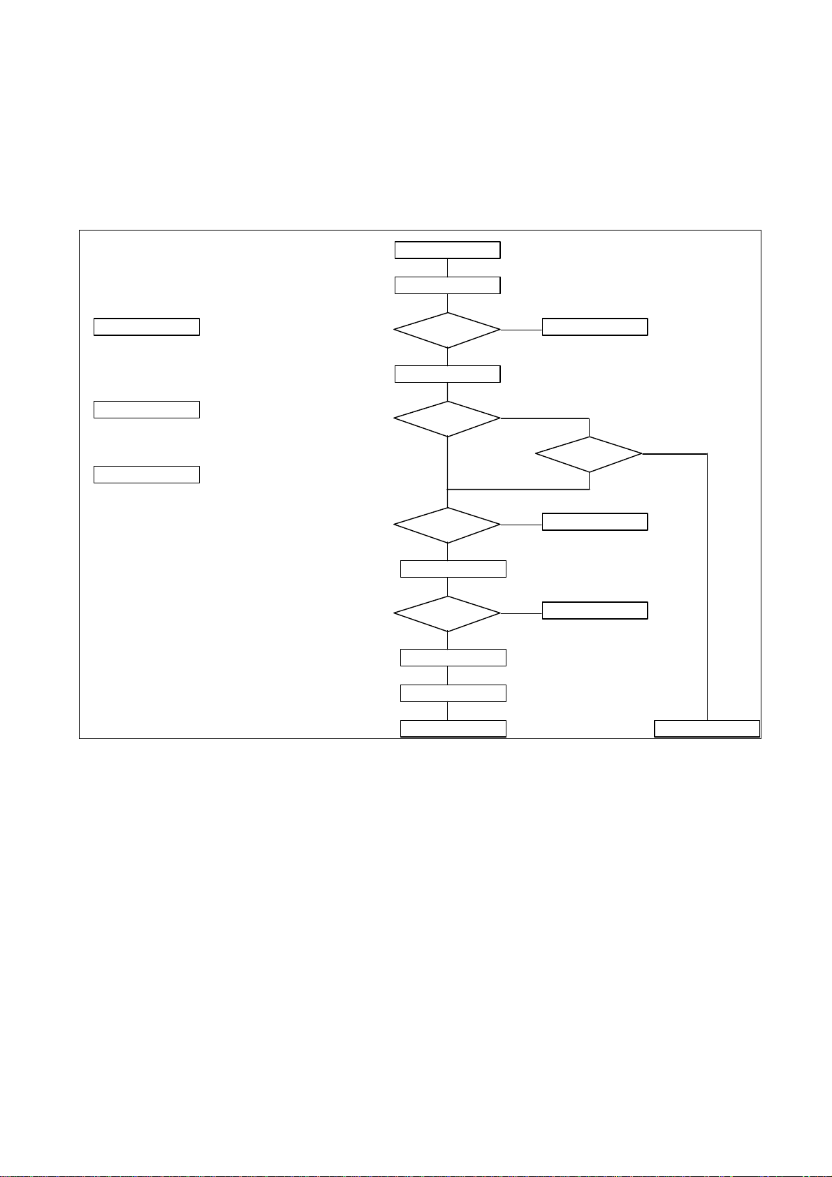
2. CLIENT/SERVER ENVIRONMENT
Flow Chart:
EV Cluster Power-on
EasyServer in
application ?
Yes
Workspots in
application ?
Yes
Cluster
configured?
Yes
No
No
No
System Power-on
System Power-on
see Release Bulletin
DataBase
No
EV Networking
accessible?
Yes
Application
4-4 (a/03.1) EasyVision RAD R4
Copyright © 2003 Philips Medical Systems Nederland B.V.
ALL RIGHTS RESERVED
Page 43

Fault Finding Section 4
3. EASYVISION RAD R4.2V2 CLUSTER NETWORK
A typical EasyVision RAD Release 4 / PCR network looks like the picture below. There are two networks:
The EasyVision cluster network (fast ethernet) and the modality network (standard Ethernet).
Another remark at this picture is that because the EasyServer is connected to two networks, it also has two
IP addresses (static router functionality), one for each network device (Ethernet controller).
IDT
Reader
EasyVision RAD
Modem
R4.2
User Terminal
Server
Single / Quad card
Onboard card
EasyVision R4.x network
10/100 Mbit
Server
User Terminal
PCR network
10/100 Mbit
Client
Workspot #1
In case of problems:
• Use ping command, see Service Manual Networking
• Check cables
• Check IP addresses
• Check Fast Ethernet HUB (led indicator)
• Check Ethernet Controllers
See Network Manual for detailed information.
EasyVision RAD R4 (a/03.1) 4-5
Copyright © 2003 Philips Medical Systems
ALL RIGHTS RESERVED
Workspot #n
Page 44
Section 4 Fault Finding
4. SUN SPARC COMPUTERS
For EasyVision RAD Release 4.2V2 the following Sun SPARC computers are used:
Ultra 10, Ultra 60, SunBlade (see belonging Unit Manual).
Flow Chart:
System Power-on Faultfinding
System Power-on
Run POST
Run POST
- diag-switch? NVRAM parameter = true
Read POST results
For POST results see Unit Manual
Forth Toolkit
For Forth Toolkit results see Unit Manual
Start-up Menu?
No
Read POST results
Identification?
No
ok
Prompt?
No
Press Stop-A
ok
Prompt?
No
Reboot System
Press Stop-A
Yes
Yes
Yes
Goto Service Menu
Solved ?
No
Forth ToolKit
Forth ToolKit
Yes
Forth ToolKit
Repair
4-6 (a/03.1) EasyVision RAD R4
Copyright © 2003 Philips Medical Systems Nederland B.V.
ALL RIGHTS RESERVED
Page 45

Fault Finding Section 4
4.1. NON-VOLATILE RAM (NVRAM) PARAMETERS
4.1.1. U
LTRA
10
Parameter name
-
-
scsi-initiator-id 7 7
keyboard-click? false false
keymap
ttyb-rts-dtr-off false false
ttyb-ignore-cd true true
ttya-rts-dtr-off false false
ttya-ignore-cd true true
ttyb-mode 9600,8,n,1,- 9600,8,n,1,ttya-mode 9600,8,n,1,- 9600,8,n,1,pcia-probe-list 1,2 1,2
pcib-probe-list 1,3,2,4,5 1,3,2,4,5
mfg-mode off off
diag-level max min
#power-cycles 74
system-board-serial # 5014450026841 (example)
system-board-date 35bd5758 (example)
fcode-debug? false false
output-device screen screen
input-device keyboard keyboard
load-base 16384 16384
boot-command boot boot
auto-boot? true true
watchdog-reboot? false false
diag-file
diag-device net net
boot-file
boot-device disk disk net
local-mac-address? false false
ansi-terminal true true
screen-#columns 80 80
screen-#rows 34 34
silent-mode? false false
use-nvramrc? false false
nvramrc devalias pgx24 /pci@1f,0..
security-mode none none
security-password
security-#badlogins 0
oem-logo 00 00 00 00 00 00 00 00 ...
oem-logo? true false
oem-banner
oem-banner? false false
hardware-revision
last-hardware-update
diag-switch? false false
Value
Default Value
EasyVision RAD R4 (a/03.1) 4-7
Copyright © 2003 Philips Medical Systems
ALL RIGHTS RESERVED
Page 46

Section 4 Fault Finding
4.1.2. U
LTRA
60
Parameter name
-
keyboard-click? false false
keymap
ttyb-rts-dtr-off false false
ttyb-ignore-cd true true
ttya-rts-dtr-off false false
ttya-ignore-cd true true
ttyb-mode 9600,8,n,1,- 9600,8,n,1,ttya-mode 9600,8,n,1,- 9600,8,n,1,pcia-probe-list 1,2 1,2
pcib-probe-list 1,3,2,4,5 1,2,2,4,5
mfg-mode off off
dial-level max min
#power-cycles 74
system-board-serial # 5014450026841 (example)
system-board-date 35bd5758 (example)
fcode-debug? false false
output-device screen:r1280x1024x76 screen
input-device keyboard keyboard
load-base 16384 16384
boot-command boot boot
auto-boot? true true
watchdog-reboot? false false
diag-file
diag-device net net
boot-file /kernel/unix
boot-device disk disk net
local-mac-address? false false
ansi-terminal true true
screen-#columns 80 80
screen-#rows 34 34
silent-mode? false false
use-nvramrc? false false
nvramrc
security-mode none none
security-password
security-#badlogins 0
oem-logo 00 00 00 00 00 00 00 00 ...
oem-logo? true false
oem-banner
oem-banner? false false
hardware-revision
last-hardware-update
diag-switch? false false
-
Value
Default Value
4-8 (a/03.1) EasyVision RAD R4
Copyright © 2003 Philips Medical Systems Nederland B.V.
ALL RIGHTS RESERVED
Page 47

Fault Finding Section 4
4.1.3. SUNB
Parameter name
test-args
diag-passes 1 1
enclosure-type 540-3256-15 No default
banner-name SUNW,Sun-Blade-1000 No default
energystar-enabled? true No default
pcia-probe-list 4,1 4,1
pcib-probe-list 5,6,1,2,3,4 5,6,1,2,3,4
local-mac-address? true false
fcode-debug? false false
silent-mode? false false
scsi-initiator-id 7 7
oem-logo 00 00 00 00 00 00 00 00 ...
oem-logo? true false
oem-banner
oem-banner? false false
ansi-terminal true true
screen-#columns 80 80
screen-#rows 34 34
ttyb-rts-dtr-off false false
ttyb-ignore-cd true true
ttya-rts-dtr-off false false
ttya-ignore-cd true true
ttyb-mode 9600,8,n,1,- 9600,8,n,1,ttya-mode 9600,8,n,1,- 9600,8,n,1,output-device screen screen
input-device keyboard keyboard
load-base 16384 16384
auto-boot? true true
boot-command boot boot
diag-file
diag-device net net
boot-file
boot-device disk disk net
use-nvramrc? true false
nvramrc
security-mode none No default
security-password No default
security-#badlogins 0
#power-cycles
diag-script none none
diag-level min min
diag-switch? false false
error-reset-recovery boot boot
LADE
1000/2000
Value
Default Value
EasyVision RAD R4 (a/03.1) 4-9
Copyright © 2003 Philips Medical Systems
ALL RIGHTS RESERVED
Page 48

Section 4 Fault Finding
4.1.4. SUNB
Parameter name
tpe-link-test? true true
scsi-initiator-id 7 7
keyboard-click? false false
keymap
ttyb-rts-dtr-off false false
ttyb-ignore-cd true true
ttya-rts-dtr-off false false
ttya-ignore-cd true true
ttyb-mode 9600,8,n,1,- 9600,8,n,1,ttya-mode 9600,8,n,1,- 9600,8,n,1,pcia-probe-list 4,1 4,1
pcib-probe-list 5,6,1,2,3,4 5,6,1,2,3,4
mfg-mode off off
diag-level min min
#power-cycles
system-board-serial
system-board-date
fcode-debug? false false
output-device screen screen
input-device keyboard keyboard
load-base 16384 16384
boot-command boot boot
auto-boot? true true
watchdog-reboot? false false
diag-file
diag-device net net
boot-file
boot-device disk disk net
local-mac-address? true false
ansi-terminal true true
screen-#columns 80 80
screen-#rows 34 34
silent-mode? false false
use-nvramrc? true false
nvramrc
security-mode none No default
security-password No default
security-#badlogins 0
oem-logo 00 00 00 00 00 00 00 00 ...
oem-logo? true false
oem-banner
oem-banner? false false
hardware-revision
last hardware update
diag-switch? false false
LADE
1500
Value
Default Value
4-10 (a/03.1) EasyVision RAD R4
Copyright © 2003 Philips Medical Systems Nederland B.V.
ALL RIGHTS RESERVED
Page 49

Fault Finding Section 4
5. SERVICE MENU
5.1. S
To access the service menu environment select 3 Go to Service Menu in the StartUp menu. Then at the
password: prompt enter password
1. Diagnostics Menu (sunvts and product diagnostics)
2. SunOs Menu (optical disk format and Sun Os commands)
3. File Menu (file transfer and manipulation commands)
4. Printer Menu (printer tests)
5. Monitor Menu (Monitor test images and adjustment)
6. PCR Systems (PCR diagnostics menu)
0 Logout
5.1.1. D
ERVICE MENU VIA SUN CONSOLE
Service Menu
===========
Enter the number of your choice: 1
IAGNOSTICS MENU
Diagnostics Menu
================
1. Start SunVts (Sunvts hardware diagnostics)
After using SunVTS, use ëExit...í in the workspace pop-up menu
to return to this menu
2. Start EasyStore DOR Test (sa0)
3. Start CT/MR input DOR Test (sa1)
4. Start Dials Test
5. Check Modemís SW Settings
Type ~. to quit the check and return to this menu.
6. Initialize Modem
7. Set Speed of Serial port
8. Start PCI Reader Interface Test
0. Return to the service menu
Enter the number of your choice: 0
Select 8. Start PCI Reader Interface Test
The System will prompt:
Connect PCR Reader testbox. Press <Enter> to continue :
after the testbox has been connected and powered press Enter, The system will respond:
PCR Reader Interface test takes about 5 seconds
if the system didn’t detect any fault condition it will return the message
PCR Reader Interface test succeeded
press <Enter> to continue
If the system detects any fault condition during this test run, i.e. if power is not applied to the test box or the
test cable is not connected to the Sun computer the system will respond:
EasyVision RAD R4 (a/03.1) 4-11
Copyright © 2003 Philips Medical Systems
ALL RIGHTS RESERVED
Page 50

Section 4 Fault Finding
poll control line , timed out
PCR Reader Interface test failed
Press <Enter> to continue :
Caution
The test program will finish the test with the following message
even if the test box was not connected during the test.
ëReader Interface Testí ended normal, status 0
Control channel and Data channel are both ok up to test box
Press <Enter> to continue:
after pressing <Enter> the system will output the Diagnostics Menu
There is no detailed error handling available which is capable to detect different levels of faulty conditions
and which allows conclusions on errors.
5.1.2. SUNOS M
SunOs Menu
==========
1. Optical Disk Format Menu.
2. SunOs: a C-shell is started in the service directory.
Type ëexití to return to this menu.
3. ADB Convert (synchronize Anatomy DataBase and Processing Keys)
3. SunOS: OpenWindows is started in the service-directory
Use ëExit...í in the workspace pop-up menu to return to this menu
0 Return to the service menu
Enter the number of your choice: 0
5.1.3. F
1 Logfiles Inspection (a C-shell is started in the log directory)
Use 'ls -l', 'more', 'tail -31l' to examine
the logfiles.
Type 'exit' to return to this menu.
2 Images Inspection (a C-shell is started in the images directory)
Use 'ls -l' to examine the image files.
Type 'exit' to return to this menu.
3 Create file /tmp/logfiles.zip containing logfiles and config files.
0 Return to Service Menu
ILE MENU
File Menu
=========
Enter the number of your choice:
ENU
4-12 (a/03.1) EasyVision RAD R4
Copyright © 2003 Philips Medical Systems Nederland B.V.
ALL RIGHTS RESERVED
Page 51

Fault Finding Section 4
5.1.4. P
5.1.5. M
5.1.6. PCR
RINTER MENU
Printer Menu
============
1 HCU Calibration (start hardcopy unit calibration)
2 Start Printer Status Request
3 Start Data Channel Printer Test
Data is sent to the HCU via the data channel, then
press print on the HCU control panel for output
4 Start Printer Test
5 Start S-bus/PCI Printer Visual Interface Test (Led board required)
0 Return to Service Menu
Enter the number of your choice:
ONITOR MENU
Monitor Menu
============
1 Start Monitor Color Map Test
2 Show LCD testimage (POPO_1288x1024.gif)
0 Return to Service Menu
Enter the number of your choice:
SYSTEMS MENU
PCR Systems Menu
================
1 File Transfer- and Compression Settings Menu
2 File Transfer Menu (log and image file transfer)
3 ADB Convert (synchronize Anatomy Data Base and Processing Keys)
4 Set Serial Interface Parameters
5 PCR Reader Documentation
0 Return to Service Menu
Enter the number of your choice:
5.1.6.1. File Transfer Settings Menu
File Transfer Settings Menu:
============================
Actual Configuration:
EasyVision RTAC: sz/rz
EasyVision RTAC: sz/rz
Compression: Zip
EasyVision RAD R4 (a/03.1) 4-13
Copyright © 2003 Philips Medical Systems
ALL RIGHTS RESERVED
Page 52

Section 4 Fault Finding
1 EasyVision RTAC: Use kermit (works only with modem
terminal
2 EasyVision RTAC: Use kermit connections)
3 EasyVision RTAC: Use sz/rz (works only with modem terminal
4 EasyVision RTAC: Use sz/rz connections)
5 EasyVision RTAC: Use ftp (works only with TCP/IP and ftp-
server running on RTAC host)
6 Zip (mostly used compression SW on DOS based
computers)
7 UNIX compress ( tar| mostly used compression SW on UNIX
based computers)
0 Return to Service Menu
Enter the number of your choice:
5.1.6.2. File Transfer Menu
File Transfer Menu
==================
Actual Configuration: RTAC EasyVision : sz/rz
EasyVision RTAC sz/rz
Compression: Zip
1 Collect & Send Logfiles
2 Send Image Files (Menu)
3 Manual File Transfer (a C-shell is started: go to the directory
where you want to send/receive files from/to.
Then start the desired protocol by typing its
name followed by the appropriate arguments:)
0 Return to Service Menu
Enter the number of your choice:
5.1.6.3. Serial Interface Menu
Serial Interface Menu:
======================
Actual Configuration:
Device: ttyb
Mode: Modem
N Set Mode to Nullmodem (RTAC-cable-EV)
M Set Mode to M odem (RTAC-modem-EV)
!!! NOTE !!!
Donít forget to (re)set this flag to Modem
if Modem connection is desired later on!
!!! NOTE !!!
0 Return to Service Menu
Enter the number of your choice:
4-14 (a/03.1) EasyVision RAD R4
Copyright © 2003 Philips Medical Systems Nederland B.V.
ALL RIGHTS RESERVED
Page 53

Fault Finding Section 4
5.1.6.4. PCR Reader Documentation
5 PCR Reader Documentation
PCR Reader Documentation
Insert the CD-ROM containing the PCR Reader Documentation
and press Return to continue:
OpenWindows and the Acrobat Reader will be started.
On ‘File’ and ‘Open’ the 'Open' window of the Acrobat Reader will be displayed.
Double click on the line /cdrom/ac500 or /cdrom/ac5000 to select the appropriate system.
The documentation files available on this CD-ROM are listed In the ‘Files’ area on the right)
Double click on the line of the document you want to open and view.
The first page of the document will be displayed
EasyVision RAD R4 (a/03.1) 4-15
Copyright © 2003 Philips Medical Systems
ALL RIGHTS RESERVED
Page 54

Section 4 Fault Finding
5.2. S
Service Menu
============
5.2.1. D
ERVICE MENU VIA SERIAL PORT
login: Service
Password: <Enter HostID>
Last login: Tue Dec 2 14:13:51 on term/b
PMSN-ICS Solaris 2.5.1 adapted for EasyVision June 1996
+-----------------------------------------------------------------+
| WARNING : Access for authorised persons only |
+-----------------------------------------------------------------+
Last local login: Tue Dec 2 11:26:37 MET 1997
1 Diagnostics Menu (sunvts and product diagnostics)
2 SunOS Menu (optical disk format and SunOS commands)
3 File Menu (file transfer and manipulation commands)
4 Printer Menu (Printer tests)
0 Logout
Enter the number of your choice:
IAGNOSTICS MENU
Diagnostics Menu
================
1 Start SunVts (Sun hardware diagnostics)
2 Start EasyStore DOR Test (sa0)
3 Start CT/MR input DOR Test (sa1)
4 Start Dials Test
0 Return to Service Menu
Enter the number of your choice:
5.2.2. SUNOS M
SunOS Menu
==========
1 Optical Disk Format Menu
2 SunOS: a C-shell is started in the service-directory
Type 'exit' to return to this menu.
0 Return to Service Menu
Enter the number of your choice:
ENU
4-16 (a/03.1) EasyVision RAD R4
Copyright © 2003 Philips Medical Systems Nederland B.V.
ALL RIGHTS RESERVED
Page 55

Fault Finding Section 4
5.2.3. F
ILE MENU
File Menu
1 Logfiles Inspection (a C-shell is started in the log directory)
Use 'ls -l', 'more', 'tail -31l' to examine
the logfiles.
Type 'exit' to return to this menu.
2 Images Inspection (a C-shell is started in the images directory)
Use 'ls -l' to examine the image files.
Type 'exit' to return to this menu.
3 Create file /tmp/logfiles.zip containing logfiles and config files.
0 Return to Service Menu
Enter the number of your choice:
The following protocols are available:
kermit
rb
rx
rz
sb
sx
sz
Files can be moved into the Zip file with long or short filenames
In case you want to use the Zip file on a DOS or MS-Windows 3.x
system, you should choose for short files names. In that case the
name of each file that is added to the Zip file will be converted
into a number. The original names will be saved in a file "index".
This index file will also be included into
the Zip file (/tmp/logfiles.zip)
The next options are available:
1 Use short filenames
2 Use long filenames
Enter your choice:
EasyVision RAD R4 (a/03.1) 4-17
Copyright © 2003 Philips Medical Systems
ALL RIGHTS RESERVED
Page 56

Section 4 Fault Finding
5.2.4. P
5.3. PCR S
RINTER MENU
Printer Menu
============
1 Start Printer Status Request
2 Start Data Channel Printer Test
Data is sent to the HCU via the data channel, then
press print on the HCU control panel for output
3 Start Printer Test
4 Start S-bus Printer Interface Test (HCU testbox required)
5 Start S-bus Printer Visual Interface Test (Led board required)
0 Return to Service Menu
Enter the number of your choice:
For test contents see Service Manual Imager Compatibility
YSTEMS MENU (REMOTE
)
SunOS 5.6
login: Service
Password: <Host ID>
Last login: Thu Sep 14 13:04:52 from 130.143.187.215
PMSN-EVM Sun Microsystems Inc. SunOS 5.6 Generic August 1997
+---------------------------------------------------+------------+
| WARNING : Access for authorised persons only |
+---------------------------------------------------+------------+
Last local login: Tue Sep 12 16:24:18 MET DST 2000
Service Menu
============
1 Diagnostics Menu (sunvts and product diagnostics)
2 SunOS Menu (optical disk format and SunOS commands)
3 File Menu (file transfer and manipulation commands)
4 Printer Menu (Printer tests)
5 PCR Systems (PCR diagnostics menu)
0 Logout
Enter the number of your choice: 5
4-18 (a/03.1) EasyVision RAD R4
Copyright © 2003 Philips Medical Systems Nederland B.V.
ALL RIGHTS RESERVED
Page 57

Fault Finding Section 4
EasyVision PCR Systems Menu (remote) ...
Default Remote File Transfer Modes:
RTAC -> EV : sz/rz
EV -> RTAC : sz/rz
Compression: Zip
Could not find Release Info File for PCR User Terminal Server.
Might be wrong release/version/level.
Press Return to continue.
PCR Systems Menu:
1 File Transfer- and Compression Settings Menu
2 File Transfer Menu (log and image file transfer)
0 Return to Main Menu
Enter the number of your choice: 1
File Transfer Settings Menu:
Actual Configuration:
EasyVision --> RTAC : sz/rz
EasyVision <-- RTAC : sz/rz
Compression : Zip
1 EasyVision --> RTAC : Use kermit (works only with modem
2 EasyVision <-- RTAC : Use kermit terminal connections)
3 EasyVision --> RTAC : Use sz/rz (works only with modem
4 EasyVision <-- RTAC : Use sz/rz terminal connections)
5 EasyVision <--> RTAC : Use ftp (works only with TCP/IP,
and ftp server must be
running on RTAC host)
6 Zip (Most used compression S/W on DOS based computer)
7 UNIX compress (tar| Most used compression S/W on UNIX based
computer)
0 Return to Service Menu
Enter the number of your choice: 5
FTP Parameter for RTAC File Transfer Menu:
Actual Settings:
RTAC host ip: service_pc
RTAC ftp user: Service
RTAC ftp password: password
RTAC ftp directory: c:/service
C Change actual settings
D Discard changes and return to File Transfer Menu
A Accept settings and return to File Transfer Menu
Enter the number of your choice: a
File Transfer Settings Menu:
Actual Configuration:
EasyVision --> RTAC : ftp
EasyVision <-- RTAC : ftp
EasyVision RAD R4 (a/03.1) 4-19
Copyright © 2003 Philips Medical Systems
ALL RIGHTS RESERVED
Page 58

Section 4 Fault Finding
Compression : Zip
1 EasyVision --> RTAC : Use kermit (works only with modem
2 EasyVision <-- RTAC : Use kermit terminal connections)
3 EasyVision --> RTAC : Use sz/rz (works only with modem
4 EasyVision <-- RTAC : Use sz/rz terminal connections)
5 EasyVision <--> RTAC : Use ftp (works only with TCP/IP,
and ftp server must be
running on RTAC host)
6 Zip (Most used compression S/W on DOS based computer)
7 UNIX compress (tar| Most used compression S/W on UNIX based
computer)
0 Return to Service Menu
Enter the number of your choice: 0
PCR Systems Menu:
1 File Transfer- and Compression Settings Menu
2 File Transfer Menu (log and image file transfer)
0 Return to Main Menu
Enter the number of your choice: 2
File Transfer Menu:
Actual Configuration: RTAC -> EasyVision: ftp
EasyVision -> RTAC: ftp
Compression : Zip
1 Collect&Send Logfiles
2 Send Image Files (Menu)
3 Manual File Transfer (a C-shell is started; go to the directory
where
you want to send/receive files from/into.
Then
start the desired protocol by typing its name
followed by the appropriate arguments).
0 Return to Service Menu
Enter the number of your choice: 1
adding: config.cfg (deflated 95%) . . . . . . . . . . . . . . . . . . .
. . . . . . . . .
adding: PTResult (deflated 54%). . . . . . . . . . . . . . . . . . . .
. . . . . . . .
adding: autoExportServer_autoExport_de25zh.env (deflated 68%)
collecting
. &zipping
. &transferring
logfiles
adding: messages.1 (deflated 92%). . . . . . . . . . . . . . . . . . .
. . . . . . . . .
adding: messages.2 (deflated 92%). . . . . . . . . . . . . . . . . . .
. . . . . . . . .
The file 'evlog.zip' is sent to your terminal host via ftp.
It is put in the directory 'c:/service'.
File transfer completed. Press Return to continue:
4-20 (a/03.1) EasyVision RAD R4
Copyright © 2003 Philips Medical Systems Nederland B.V.
ALL RIGHTS RESERVED
Page 59

Fault Finding Section 4
File Transfer Menu:
Actual Configuration: RTAC -> EasyVision: ftp
EasyVision -> RTAC: ftp
Compression : Zip
1 Collect&Send Logfiles
2 Send Image Files (Menu)
3 Manual File Transfer (a C-shell is started; go to the directory
where
you want to send/receive files from/into.
Then
start the desired protocol by typing its name
followed by the appropriate arguments).
0 Return to Service Menu
Enter the number of your choice: 0
PCR Systems Menu:
1 File Transfer- and Compression Settings Menu
2 File Transfer Menu (log and image file transfer)
0 Return to Main Menu
Enter the number of your choice: 0
Service Menu
============
1 Diagnostics Menu (sunvts and product diagnostics)
2 SunOS Menu (optical disk format and SunOS commands)
3 File Menu (file transfer and manipulation commands)
4 Printer Menu (Printer tests)
5 PCR Systems (PCR diagnostics menu)
0 Logout
EasyVision RAD R4 (a/03.1) 4-21
Copyright © 2003 Philips Medical Systems
ALL RIGHTS RESERVED
Page 60

Section 4 Fault Finding
6. FILE SYSTEM
6.1. /DBADMIN
dbadmin is a backup directory for configuration files.
-rw-r----- 1 EasyUser EasyGrp 106029 Nov 11 20:27 8087f688.cus
-rw-r----- 1 EasyUser EasyGrp 8680 Nov 11 20:27 Configuration.pf
-rw-r----- 1 EasyUser EasyGrp 18747 Nov 11 20:27 config.cfg
drwxr-x--- 4 EasyUser EasyGrp 512 Nov 3 14:59 db8087f688
-rw-r----- 1 EasyUser EasyGrp 4276 Nov 11 20:27 license.dat
drwxr-x--- 2 EasyUser EasyGrp 8192 Oct 24 11:47 lost+found
drwxr-x--- 4 EasyUser EasyGrp 512 Oct 27 14:58 setup
-rw-r----- 1 EasyUser EasyGrp 635 Nov 11 20:27 usedSlices
8087f688.cus Customization file
Configuration.pf Property file, binary format
config.cfg Configuration file
db8087f688 Database ID file, binary format
license.dat License file
usedSlices Overview of used slices
setup Setup database backup directory
6.1.1. /
EASY/SERVICE/IMAGES/EXPORT
Description: Export images from database (max. 5 images)
link: export -> /easydata/export_img
6.2. /
Description: Configuration directory for EasyVision Application
-rw-r--r-- 1 root other 106029 Nov 11 20:27 8087f688.cus
-rw-r--r-- 1 root other 18747 Nov 11 20:27 config.cfg
drwxr-xr-x 2 EasyUser EasyGrp 512 Nov 11 12:48 export_img
drwxr-xr-x 2 EasyUser EasyGrp 512 Nov 11 12:48 filePrints
drwxr-xr-x 2 EasyUser EasyGrp 512 Nov 11 12:48 jpeg
-rw-r--r-- 1 root other 4276 Nov 11 20:27 license.dat
-rw-r--r-- 1 root other 4276 Nov 5 12:58 license.dat.~1~
-rw-rw-r-- 1 root EasyGrp 30 Nov 11 20:27 license.env
drwx------ 2 root root 8192 Nov 11 12:47 lost+found
-rw-rw-r-- 1 root EasyGrp 6 Nov 11 20:27 orig..language
-rw-rw-r-- 1 root EasyGrp 4276 Nov 11 20:27 orig.license.dat
-rw-rw-r-- 1 root EasyGrp 30 Nov 11 20:27 orig.license.env
drwxr-xr-x 2 EasyUser EasyGrp 512 Nov 11 12:48 pictures
drwxr-xr-x 2 EasyUser EasyGrp 512 Nov 11 20:27 prop
-rw-rw-r-- 1 root EasyGrp 15639 Nov 11 20:27 rebootData
drwxr-xr-x 2 EasyUser EasyGrp 512 Nov 11 12:48 text
license.dat: License file for EasyVision application
Example:
SERVER ev1 8087f688 2900
4-22 (a/03.1) EasyVision RAD R4
EASYDATA
Copyright © 2003 Philips Medical Systems Nederland B.V.
ALL RIGHTS RESERVED
Page 61

Fault Finding Section 4
DAEMON easylicd /easy/appl/bin
INCREMENT EasyServer easylicd 4.100 01-may-1998 1 3C237534749A7547D247 " " 8087f688
INCREMENT EasyClient easylicd 4.100 01-may-1998 1 8C9365C43C3A52289E8F " " 8087f688
INCREMENT EasyReview easylicd 4.100 01-may-1998 1 4C3375A46690863BDD5B " " 8087f688
INCREMENT Navigator easylicd 4.100 01-may-1998 1 6C2315449AA892663DB3 " " 8087f688
INCREMENT EasyView easylicd 4.100 01-may-1998 1 9CD3A5F4F74B79D5A525 " " 8087f688
INCREMENT BolusChaseClient easylicd 4.100 01-may-1998 1 9CB3B594FEA144DC93F0 " " 8087f688
INCREMENT BolusChaseServer easylicd 4.100 01-may-1998 1 DC93B5A49E583F882E50 " " 8087f688
INCREMENT SpineClient easylicd 4.100 01-may-1998 1 8CC3E5A4C0484F6AF994 " " 8087f688
INCREMENT SpineServer easylicd 4.100 01-may-1998 1 8CA3F5E4D0303A2DF803 " " 8087f688
INCREMENT ColonMap easylicd 4.100 01-may-1998 1 3C6385E41183B87045DF " " 8087f688
Explanation:
INCREMENT EasyCorrect easylicd 4.100 01-may-1998 1 CC63A51428AD7C3FEF38 " " 8087f688
Application License Prog. Expiration date Key Comment Host-ID
hosts:
The hosts file is a local database that associates the names of hosts with their Internet Protocol (IP)
addresses. The hosts file can be used in conjunction with, or instead of, other hosts databases, including
the Domain Name System (DNS), the NIS hosts map and the NIS+ hosts table. Programs use library
interfaces to access information in the hosts file.
The hosts file has one entry for each IP address of each host. If a host has more than one IP address, it
will have one entry for each, on consecutive lines.
#
# Sun Host Database
#
# If the NIS is running, this file is only consulted when booting
#
127.0.0.1 localhost
#
192.168.12.64 ev1 loghost
222.222.222.221 evppp
222.222.222.222 remoteppp
192.168.12.80 ev2
Explanation:
127.0.0.1 localhost for loopback
192.168.12.64 ev1 loghost own IP-address, always followed by loghost
222.222.222.221 evppp own PPP connection IP address
222.222.222.222 remoteppp remote PPP connection address
192.168.12.80 ev2 other host
6.2.1. /VAR/ADM/CDSLOG
autoExportServer_autoExport_ev1.env
autoExportServer_autoExport_ev1.log
autoExportServer_autoExport_ev1.startup
computeServer_compute_ev1.env
computeServer_compute_ev1.log
computeServer_compute_ev1.startup
dbServer_db8087f688.env
dbServer_db8087f688.log
dbServer_db8087f688.startup
deleteServer_delete_ev1.env
deleteServer_delete_ev1.log
setupDbServer_setup.startup
systemMonitor_systemMonitor_ev1.env
systemMonitor_systemMonitor_ev1.log
systemMonitor_systemMonitor_ev1.startup
template.env
uiDataHandling_uiDataHandling_ev1.env
uiDataHandling_uiDataHandling_ev1.log
uiDataHandling_uiDataHandling_ev1.start
up
uiDentalView_uiDentalView_ev1.env
uiDentalView_uiDentalView_ev1.log
EasyVision RAD R4 (a/03.1) 4-23
Copyright © 2003 Philips Medical Systems
ALL RIGHTS RESERVED
Page 62

Section 4 Fault Finding
deleteServer_delete_ev1.startup
dorServer_dor_ev1.env
dorServer_dor_ev1.log
dorServer_dor_ev1.startup
hcServer_hcs0_ev1.env
hcServer_hcs0_ev1.log
hcServer_hcs0_ev1.startup
httpServer_http_ev1.env
httpServer_http_ev1.log
httpServer_http_ev1.startup
lmgrd.startup
networkServer_export_ev1.env
networkServer_export_ev1.log
networkServer_export_ev1.startup
networkServer_import_ev1.env
networkServer_import_ev1.log
networkServer_import_ev1.startup
setup
setupDbServer_setup.env
setupDbServer_setup.log
uiDentalView_uiDentalView_ev1.startup
uiPerfusion_uiPerfusion_ev1.env
uiPerfusion_uiPerfusion_ev1.log
uiPerfusion_uiPerfusion_ev1.startup
uiRF_uiRF_ev1.env
uiRF_uiRF_ev1.log
uiRF_uiRF_ev1.startup
uiStackView_uiStackView_ev1.env
uiStackView_uiStackView_ev1.log
uiStackView_uiStackView_ev1.startup
uiVolume_uiVolume_ev1.env
uiVolume_uiVolume_ev1.log
uiVolume_uiVolume_ev1.startup
xConfig_xConfig.env
xConfig_xConfig.log
xConfig_xConfig_ev1.startup
xEasyReview_xEasyReview_ev1.env
xEasyReview_xEasyReview_ev1.log
xEasyReview_xEasyReview_ev1.startup
4-24 (a/03.1) EasyVision RAD R4
Copyright © 2003 Philips Medical Systems Nederland B.V.
ALL RIGHTS RESERVED
Page 63

Fault Finding Section 4
7. EASYVISION LOG FILES
EasyVision RAD provides log files for operating system and application software.
Messages logged by the Solaris operating system can be found in the directory /var/adm in the files named
messages, messages.1 and messages.2 . The logs contain messages of the operating system like errors,
start-up messages and warnings.
The file messages contains the latest logs. When this file reaches a defined size messages.2 is deleted,
messages.1 renamed to messages.2 and messages becomes messages.1.
Log files of the application software are written to /var/adm/cdslog.
Important logs are:
file name software task / usage
cdRecordableServer_cdRecordable.log CD-R server
computeServer_compute.log
dbServer_db.log database server
hcServer_hcs0.log hardcopy unit server, printing
networkReaderServer_dmsReader.log Reader server for DMS Readers: AC3/000, 9000
networkReaderServer_networkReader.log Reader server for DICOM Readers: AC5/000, Compano
networkServer_export.log Network server for export jobs
networkServer_import.log Network server for import jobs
printJobServer_printJob.log
systemMonitor_systemMonitor.log System monitor, observes all software tasks
System Monitor
The system monitor performs the task to run other processes. If a process crashes, the system monitor tries
to restart that process. It also knows if a process is critical or not, and can decide to stop that specific
program or to stop the whole application.
Critical processes: dBServer
SetupServer
Non-critical processes: a specific application, e.g. BCR, 3D etc
http server
Server
Each process has its own error log files. It depends on which configuration (software options) you have what
logfiles are written in the logfile directory.
AutoExport Server
This process is responsible for all auto export actions.
ComputeServer
The compute server performs tasks for other facilities, such as 3D calculation, BCR, etc.
dbServer
The database server handles all read, write, seek etc actions in the image database.
deleteserver
The delete server is a process dat performs several possibilities of deletion tasks. These tasks can be
configured on the Customizing panel. For example, Protect, Protect until printed, Protect until stored on
optical disk, Auto-expiration Interval of 12 hours etc.
dorServer
This server handles the optical disk as a normal image database.
httpServer
Serves http requests over serial (PPP) or network.
EasyVision RAD R4 (a/03.1) 4-25
Copyright © 2003 Philips Medical Systems
ALL RIGHTS RESERVED
Page 64

Section 4 Fault Finding
p
network server
There are two network servers: import and export.
setupDBserver
The setup database server handles the configuration of a system. The setupDbServer runs on the Server
system. Once the Server system is running, the clients can take their own configuration and the
configuration of the remote hosts or modalities from the setup database. In case of a stand-alone, the Server
is integrated in the same machine.
UI...
The ui.. processes, e.g. uiRF, uiVolume, (dependent of applications) give detailed information about the
packages mentioned with the question mark.
If such an application is unstable, messages are written in the ui? logfile. If a critical error occurs, this error is
also written in the error.log file.
Lmgrd.startup
The license manager checks if the license is correct for the requested application. Without a license for a
specific package it is impossible to run that application. The license.dat file has been uploaded in the
/easydata directory. Only in case of a Server or Standalone:
Wrong Host-ID Example:
17:01:39 (lmgrd) FLEXlm (v5.12a) started on ev1 (Sun) (12/10/1997)
17:01:39 (lmgrd) FLEXlm Copyright 1988-1996, Globetrotter Software, Inc.
17:01:39 (lmgrd) World Wide Web: http://www.globetrotter.com
17:01:39 (lmgrd) License file: "/easydata/license.dat"
17:01:39 (lmgrd) Starting vendor daemons ...
17:01:39 (lmgrd) Started easylicd (internet tcp_port 32810 pid 2336)
17:01:39 (easylicd) Wrong hostid, exiting (expected 8087f687, got 8087f688).
17:01:39 (lmgrd) Please correct problem and restart daemons
17:01:45 (lmgrd) lmgrd will now shut down all the vendor daemons
install.log
The installation logfile install.log can be found in the /var/adm/cdslog/setup directory. In this file errors during
installation are written.
7.1. C
OLLECTING LOG FILES
There is a function implemented in the software to collect automatically or manually all log and config files
and compress it to a ZIP archive named evlog.zip. This file is only generated on EasyVision RAD systems
and contains additional PCR specific files, different to other EasyVisions where the file is named
logfiles.zip.
evlog.zip is created in the sub-directory /var/adm (see procedure below). An existing evlog.zip file is
renamed to evlog0.zip, evlog0.zip to evlog1.zip, and so on (up to evlog3.zip).
evlog.zip is also generated automatically when the software detects a crash of a system process.
When sending error logs to the field assistance group in Hamburg, please, please,
lease send always evlog.zip not logfiles.zip.
evlog.zip contains:
-
all log and messages files
-
all config, customization and calibration files
-
license.dat (software license)
-
all PCR relevant files of /easydata/UI/configuration
-
setup database (ZIP)
evlog.zip can be generated manually using the following procedure:
4-26 (a/03.1) EasyVision RAD R4
Copyright © 2003 Philips Medical Systems Nederland B.V.
ALL RIGHTS RESERVED
Page 65

Fault Finding Section 4
1. From the Start Menu select
2. Select 2 Go to Service Menu
Password: password
3. Select 6 PCR Systems
4. Select 2 File Transfer Menu
5. Select 1 Collect Logfiles
7.2. TCP C
ONNECTION
First of all a TCP connection is created between the hosts who want to communicate via the DICOM
protocol. The following example gives the connection between an EasyVision (EV1) and a DICOM node
(DICOM1) at port 50082. In fact the DICOM connection is initiated at the port (DICOM listen port) written in
the Conformance Statement, but the child process is transferred to port 50082. Now the server can start
another TCP connection.
The next line is written in the logfile:
Jul 25 10:06:23 EV1 sunConfig: Info:CREATED TCP CONNECTION from host: [EV1] to
host: [DICOM1] at port: [50082].
When the TCP connection is released the following line appears in the logfile
Jul 25 10:06:26 EV1 sunConfig: Info:RELEASED TCP CONNECTION from host: [EV1] to
host: [DICOM1].
7.3. A
SSOCIATION
PDU T
YPES
The Protocol Data Units (PDUs) are the DICOM packets (containing messages/data/comments) exchanged
between peer entities within a DICOM layer. It consists of protocol control information and user data. PDUs
are constructed by mandatory fixed fields followed by optional variable fields that contain one or more items
and/or sub-items.
After creating a TCP connection the PDU types are associated. The EasyVision sends a PDU type to the
remote DICOM node as the requestor.
Jul 25 10:06:23 EV1 sunConfig: Info:SENT: [ASSOCIATE_RQ_PDU_TYPE] from: [EV1] to : [DICOM1].
Next the EasyVision receives a PDU type from the remote DICOM node. The remote DICOM node is the acceptor.
If these services are confirmed a DICOM association is made:
Jul 25 10:06:25 EV1 sunConfig: Info:ESTABLISHED DICOM ASSOCIATION from: [EV1] to : [DICOM1].
If not, messages like these are written:
Jul 25 10:06:25 EV1 sunConfig: Info:[049SBCDC01DIC1] REJECTS following
PRESENTATION CONTEXTS from: [EV1]:
ID ABSTRACT_SYNTAX TRANSFER_SYNTAX
REJECT_REASON
007 1.2.840.10008.5.1.4.1.1.1 1.2.840.10008.1.2.4.70
This means that the abstract syntax CR-Image Store via the transfer syntax JPEG Lossless (see DICOM
Conformance Statement) is not accepted.
EasyVision RAD R4 (a/03.1) 4-27
Copyright © 2003 Philips Medical Systems
ALL RIGHTS RESERVED
Page 66

Section 4 Fault Finding
7.4. A
Once the DICOM association is confirmed the accepted presentation context are written in the logfile:
ACCEPTED PRESENTATION CONTEXTS:
ID ABSTRACT_SYNTAX TRANSFER_SYNTAX
001 1.2.840.10008.5.1.4.1.1.1 1.2.840.10008.1.2
003 1.2.840.10008.5.1.4.1.1.1 1.2.840.10008.1.2.1
005 1.2.840.10008.5.1.4.1.1.1 1.2.840.10008.1.2.2
009 1.2.840.10008.5.1.4.1.1.2 1.2.840.10008.1.2
011 1.2.840.10008.5.1.4.1.1.2 1.2.840.10008.1.2.1
013 1.2.840.10008.5.1.4.1.1.2 1.2.840.10008.1.2.2
017 1.2.840.10008.5.1.4.1.1.4 1.2.840.10008.1.2
019 1.2.840.10008.5.1.4.1.1.4 1.2.840.10008.1.2.1
021 1.2.840.10008.5.1.4.1.1.4 1.2.840.10008.1.2.2
025 1.2.840.10008.5.1.4.1.1.5 1.2.840.10008.1.2
027 1.2.840.10008.5.1.4.1.1.5 1.2.840.10008.1.2.1
029 1.2.840.10008.5.1.4.1.1.5 1.2.840.10008.1.2.2
033 1.2.840.10008.5.1.4.1.1.6 1.2.840.10008.1.2
035 1.2.840.10008.5.1.4.1.1.6 1.2.840.10008.1.2.1
037 1.2.840.10008.5.1.4.1.1.6 1.2.840.10008.1.2.2
041 1.2.840.10008.5.1.4.1.1.7 1.2.840.10008.1.2
043 1.2.840.10008.5.1.4.1.1.7 1.2.840.10008.1.2.1
045 1.2.840.10008.5.1.4.1.1.7 1.2.840.10008.1.2.2
In this example CR-Image Storage (
(
1.2.840.10008.1.2)
1.2.840.10008.1.2.2)
7.5. L
CCEPTED PRESENTATION CONTEXTS
1.2.840.10008.5.1.4.1.1.1)
OCAL
, Explicit VR little Endian (
.
/ P
EER INFORMATION
1.2.840.10008.1.2.1)
is accepted via Implicit VR Little Endian
, and Explicit VR Big Endian
After the accepted presentation context tables are written in the logfile, the LOCAL / PEER parameters are
displayed.:
ApplicationContextName: [1.2.840.10008.3.1.1.1]
LOCALMaxDataPDULength: [0]
PEERMaxDataPDULength: [16384]
LOCALImplementationClassUID: [1.3.46.670589.5.2.2]
PEERImplementationClassUID: [1.3.12.2.1107.5.1995.1]
LOCALImplementationVersionName: [EVCTMR21]
PEERImplementationVersionName: [SIEMENS_DICOM_10]
MaxOperationsInvoked: [1]
MaxOperationsPerformed: [1]
7.5.1. A
Two Application Entities establish an association by agreeing on an application context. The requester of an
association proposes an Application Context Name and the acceptor returns either the same or a different
Application Context Name. The returned name specifies the application context to be used for this
association.
According to the DICOM Standard a single DICOM Application Context Name is "1.2.840.10008.3.1.1.1".
7.5.2. L
According to the DICOM standard a PDU Length of 0 means that the maximum length is unlimited. Some
DICOM nodes do not understand a maximum PDU length of 0 bytes. The following error message is written:
Jul 25 10:06:30 EV1 sunEasyVision: ObjC [nil@0x0] Received: [DATA_TF_PDU_TYPE]
has unexpected PDULength : [0], expected > [6]. -- (TBX,W)
PPLICATION CONTEXT NAME
OCAL MAX DATA
PDU L
ENGTH
4-28 (a/03.1) EasyVision RAD R4
Copyright © 2003 Philips Medical Systems Nederland B.V.
ALL RIGHTS RESERVED
Page 67

Fault Finding Section 4
In this case a PDU length = 0, but the remote system expects a value greater than 6 bytes (header). In fact
it expects 6 bytes plus the real PDU length or shorter. 0 < x =< PDU length
The DICOM association shall be disconnected because of the invalid PDU Length:
Jul 25 10:06:30 EV1 sunEasyVision: ObjC [DULConnection@0xdd9328 __abort:reason:]
Sent: [ABORT_PDU_TYPE] with SOURCE: [ABORT_AS_DUL_PROVIDER] and REASON:
[ABORT_INVALID_PDU_PARAMETER] from: [EV1] to: [DICOM1] (aborting...). -- (TBX,W)
Jul 25 10:06:30 EV1 sunEasyVision: Info:RELEASED TCP CONNECTION from host: [EV1]
to host: [DICOM1].
7.5.3. P
The maximum PDU length the remote DICOM node can handle. In this case a maximum of 16384 bytes is
allowed.
7.5.4. I
The implementation identification notification allows implementations of communicating AEs to identify each
other at Association establishment time. It is intended to provide respective (each network node knows the
other's implementation identity) and non-ambiguous identification in the event of communication problems
encountered between two nodes. This negotiation is required.
Implementation identification relies on two pieces of information:
• Implementation Class UID (required);
• Implementation Version Name (optional).
LOCALImplementationClassUID:
PEERImplementationClassUID:
LOCALImplementationVersionName:
For example: EVXR31. EVCTMR21.
PEERImplementationVersionName:
7.5.5. M
EER MAX DATA
MPLEMENTATION IDENTIFICATION NOTIFICATION
AX OPERATIONS
PDU L
ENGTH
defined registered value by the ISO
defined registered value by the ISO
The version name extracted from the EasyVision software.
The implementation version name of the remote DICOM node.
The maximum number of outstanding operations and/or sub-operations it may invoke or performed
asynchronously.
The EasyVision does not support asynchronous operations. (see Conformance Statement)
7.6. V
The verifying of the DICOM syntaxes starts with (e.g. verifying SC-Image Store):
Mar 17 11:14:23 EV1 networkServer_network_EV1: Info:START VERIFYING:
[1.2.840.10008.5.1.4.1.1.7] from: [EV1] to: [DICOM1]
Next a syntax check is written:
Mar 17 11:14:23 EV1 networkServer_network_EV1: Info:LOG: 1, REPAIR: 1,
SYNTAX_CHECK: 1, REJECT: 1, PMSNET: 0, GCOM: 0, PURE: 0.
LOG: boolean 1: logging per attribute 0: no specific logging per attribute
REPAIR: boolean 1: repair attribute 0: not repair attribute
REJECT: boolean 1: do not put image in database 0: put image in database
PMSNET: boolean 1: convert to PMSNet 0: do not convert PMSNet
GCOM: boolean 1: convert to GCOM 0: do not convert GCOM
PURE: boolean 1: accept only DICOM attributes 0: do not accept only DICOM attrbutes
EasyVision RAD R4 (a/03.1) 4-29
ERIFYING SYNTAXES
Copyright © 2003 Philips Medical Systems
ALL RIGHTS RESERVED
Page 68

Section 4 Fault Finding
(See the advanced DICOM menu configuration for changing LOG, REPAIR, REJECT, PURE)
7.6.1. S
If syntax errors occur lines like following messages are written in the logfile:
Aug 13 13:05:54 EV1 networkServer_import_EV1: Info:BasicVerifier: repaired DICOM
attribute (0x0008, 0x0023) [SPI_IMAGE_DATE]
In this case a DICOM attribute (Image date) is repaired.
Another examples gives a syntax check where PURE is set to 0:
Mar 17 11:14:24 EV1 networkServer_network_EV1: Info:NON PURE DICOM attribute:
(0x0011, 0x1110) [SPI_PATIENT_ENTRY_ID]
Mar 17 11:14:24 EV1 networkServer_network_EV1: Info:NON PURE DICOM attribute:
(0x0009, 0x1051) [SPI_STUDY_UNIQUE_IDENTIFIER]
In this case all Non Pure DICOM attribute (0x0011, 0x1110 and 0x0009, 0x1051) are not accepted.
7.7. C
Closing a DICOM connection is done via:
Jul 25 10:06:25 EV1 sunConfig: Info:SENT: [RELEASE_RQ_PDU_TYPE] from: [EV1] to:
[DICOM1].
Jul 25 10:06:26 EV1 sunConfig: Info:RECEIVED: [RELEASE_RP_PDU_TYPE] from:
[DICOM1] to: [EV1].
Jul 25 10:06:26 EV1 sunConfig: Info:RELEASED TCP CONNECTION from host: [EV1] to
host: [DICOM1].
First of all the requestor sends a PDU Type release to the remote DICOM node. Next a response is
received, and finally the TCP connection is closed.
YNTAX ERRORS
LOSING
DICOM
CONNECTION
4-30 (a/03.1) EasyVision RAD R4
Copyright © 2003 Philips Medical Systems Nederland B.V.
ALL RIGHTS RESERVED
Page 69

Replacements Section 5
Section 5 Replacements
Contents
1.
2.
IMPORTANT ........................................................................................................................................... 3
SUN WORKSTATION ............................................................................................................................ 3
2.1. MotherBoard ........................................................................................................................................... 3
2.2. NVRAM ................................................................................................................................................... 3
2.3. Memory ................................................................................................................................................... 4
2.4. System Disk ............................................................................................................................................ 4
2.5. Image Disks ............................................................................................................................................ 4
2.6. DVD / CD Drive ....................................................................................................................................... 6
2.7. PCI Cards................................................................................................................................................ 6
2.8. Power Supply .......................................................................................................................................... 6
2.9. Various Ultra 10/60, SunBlade Parts ...................................................................................................... 7
3.
PERIPHERAL CABINET........................................................................................................................ 7
3.1. Image Disks ............................................................................................................................................ 7
3.2. EasyStore optical disk drive .................................................................................................................... 7
3.3. EasyStore Recordable ............................................................................................................................ 7
3.4. Power Supply .......................................................................................................................................... 8
4.
MONITOR ............................................................................................................................................... 8
5.
DOME MD2 FRAMEBUFFER ................................................................................................................ 8
5.1. Ultra 10................................................................................................................................................... 8
5.2. Ultra 60.................................................................................................................................................... 8
5.3. SunBlade................................................................................................................................................. 9
EasyVision RAD R4 (a/03.1) 5-1
Copyright © 2003 Philips Medical Systems Nederland B.V.
ALL RIGHTS RESERVED
Page 70

Section 5 Replacements
5-2 (a/03.1) EasyVision RAD R4
Copyright © 2003 Philips Medical Systems Nederland B.V.
ALL RIGHTS RESERVED
Page 71

Replacements Section 5
1. IMPORTANT
After a hardware modification reboot always with: ok boot -r
• Shut down the EasyVision.
• Power on
• Wait for the EasyVision/Sun logo to appear.
• Press <STOP>+<A> during the memory test.
• Now the system will return to the ok prompt.
• Enter boot -r
2. SUN WORKSTATION
2.1. M
Step Action Refer to Remark 1 Replace motherboard Manual: Unit Manual Ultra 10/ 60,
OTHERBOARD
SunBlade
Section: Replacements
Chapter:
replacement
Motherboard and Component
Disconnect all connectors
and remove PCI cards, UPA
cards, DIMM's, NVRAM, etc.
2.2. NVRAM
Step Action Refer to Remark
1 Replace NVRAM Manual: Unit Manual Ultra 10/ 60,
SunBlade
2 Re-install operating
system and
application software
3 - Reload backup files
(if not present in
/dbadmin)
- Rename:
<old_hostid>.cus
to
<new_hostid>.cus
4 - Adapt EasyVision
configuration panel
- Execute config
Section:
Chapter: Motherboard and Component
replacement
Manual:
Chapter: Software installation
Manual:
Chapter: Appendix Backup and Restore
Manual:
Chapter:
Paragraph:
Replacements
Release Bulletin
Release Bulletin
Release Bulletin
Configuring
Execute the configuration
Replacing the NVRAM (new
HostID) will require a new
software license file
The correct NVRAM settings
for EasyVision are installed
Backup files are:
license.dat (License file)
setupDB.bck (setup
database)
In EasyVision configuration
panel : change hostid to
<new_hostid>
Do not change ‘image
database identification’
otherwise the image
database will be lost !!!
EasyVision RAD R4 (a/03.1) 5-3
Copyright © 2003 Philips Medical Systems Nederland B.V.
ALL RIGHTS RESERVED
Page 72

Section 5 Replacements
2.3. M
Step Action Refer to Remark
1 Replace the DIMM Manual: Unit Manual Ultra 10/ 60,
EMORY
SunBlade
Section:
Chapter:
replacement
Replacements
Motherboard and Component
2.4. S
Step Action Refer to Remark
1 Remove the system disk Manual: Unit Manual Ultra 10/ 60,
2 Replace the system disk Manual: Unit Manual Ultra 10/ 60,
3 Re-install OS and AS Manual: Release Bulletin
4 Reload backup files (if
not present in /dbadmin)
5 Execute config Manual: Release Bulletin
YSTEM DISK
SunBlade
Section: Replacements
Chapter: Storage Devices
SunBlade
Section: Replacements
Chapter: Storage Devices
Chapter: Software installation
Manual: Release Bulletin
Chapter: Appendix File Transfer
Chapter: Configuring
Paragraph: Execute the configuration
No jumper settings are
required.
Backup files are:
license.dat (License file)
config.cfg (Configuration
file)
<hostid>.cus
(Customization file)
<host_name>.cal (HCU
Calibration file)
2.5. I
Image disks could either be located in a peripheral cabinet or in the Sun Ultra or SunBlade computer.
Before replacing an image disk the file vfstab must be modified:
1. Restart the EasyVision.
2. At the EASYVISION STARTUP MENU :
- Select 3 Go to Service Menu
- Password: password
- Select 2 SunOS Menu
- Select 3 SunOS: OpenWindows
3. Enter cp /etc/vfstab /etc/vfstab_backup
4. Enter textedit /etc/vfstab
5. Within textedit delete all lines which are related to the image disk(s).
5-4 (a/03.1) EasyVision RAD R4
MAGE DISKS
Copyright © 2003 Philips Medical Systems Nederland B.V.
ALL RIGHTS RESERVED
Page 73

Replacements Section 5
Depending on the SCSI-Controller-Port on which the image disks are connected the entries in vfstab
are different.
If the first controller is used the image disk entries are related to:
c1t11d0sx = 1st image disk (t11)
c1t10d0sx = 2nd image disk (t10)
c1t9d0sx = 2rd image disk (t9)
c1t8d0sx = 4th image disk (t8)
If the the second controller is used the image disk entries are related to:
c2t11d0sx = 1st image disk
c2t10d0sx = 2nd image disk
c2t9d0sx = 2rd image disk
c2t8d0sx = 4th image disk
Delete for instance the following text (make sure all "Additional image disks"-entries including all
"...... /dbadmin ufs ......"-entries are deleted!).: This means the whole line.
6. Save the file vfstab and quit textedit.
7. Delete the file /etc/vfstab% created by textedit by entering rm /etc/vfstab%
8. Shutdown and power-off the EasyVision (disconnect the mains power cable!).
9. Power-off the peripheral cabinets (disconnect the mains power cable!).
10. Now replace or add the image disk(s):
For external image disk(s):
Disconnect the peripheral cabinet and remove the defective image disk and replace it with the new one
(mind the jumper settings of the new disk!).
For internal image disk:
Open the Sun computer(see Service Manual) and replace the defective image disk by a new one (mind
the jumper settings of the new disk!).
11. Power-on the peripheral cabinet(s).
12. Power-on the EasyVision and press <Stop> + <a> during memory initialization.
13. At the ok prompt enter boot -r
14. At the EASYVISION STARTUP MENU :
- Select 3 Go to Service Menu
- Password: password
- Select 2 SunOS Menu
- Select 3 SunOS: OpenWindows
15. At the # prompt enter format
16. Select the replaced disk (cXt11, cXt10 etc.).
17. The following question is asked, when the disk is not labeled "Disk not labeled. Label it now?".
Answer with: y
18. After labeling the disk quit the format menu, exit OpenWindows and exit the Service Menu.
EasyVision RAD R4 (a/03.1) 5-5
Copyright © 2003 Philips Medical Systems Nederland B.V.
ALL RIGHTS RESERVED
Page 74

Section 5 Replacements
19. Re-install the Application Software. During installation you will be asked which disks shall be used as
image disk(s). See also: Release Bulletin Chapter Installing the Application Software.
20. Start configuration. Answer "Try to reload backup version?" with: OK
21. Execute configuration ("Keep existing image database" is grayed out, because there is no image
database yet!) If necessary, the amount of the used image-disk-size can be reduced at this point as
well.
22. Reboot the system.
2.6. DVD / CD D
Step Action Refer to Remark
1 Remove the drive Manual: Unit Manual Ultra 10/ 60,
2 Set jumpers on new
drive
3 Replace the drive Manual: Unit Manual Ultra 10/ 60,
2.7. PCI C
ARDS
RIVE
SunBlade
Section: Replacements
Chapter:
Manual: System Manual
EasyVision
Section: Programmings
SunBlade
Section: Replacements
Chapter: Storage Devices
Storage Devices
SunBlade 1000/2000: SCSI DVD
SunBlade 1500 : IDE DVD
Ultra 60: SCSI CD-ROM
Ultra 10: IDE CD-ROM
Step Action Refer to Remark
1 Remove the PCI card Manual: Unit Manual Ultra 10/ 60,
SunBlade
Section:
Chapter: Mother board and
Component replacement
2 Set jumpers Manual: System Manual EasyVision
Section: Programmings
3 Replace the PCI card Manual: Unit Manual Ultra 10/ 60,
SunBlade
Section:
Chapter:
Component replacement
2.8. P
Step Action Refer to Remark
1 Replace the Power Supply Manual: Unit Manual Ultra 10/ 60,
5-6 (a/03.1) EasyVision RAD R4
OWER SUPPLY
SunBlade
Section:
Chapter:
Power Supply
Copyright © 2003 Philips Medical Systems Nederland B.V.
Replacements
Replacements
Mother board and
Replacements
Major subassemblies /
ALL RIGHTS RESERVED
Not all PCI cards have
jumper settings.
Page 75

Replacements Section 5
2.9. V
Step Action Refer to Remark
1 Remove parts Manual: Unit Manual Ultra 10/ 60,
2 Replace parts Manual: Unit Manual Ultra 10/ 60,
ARIOUS ULTRA
10/60, SUNB
SunBlade
Section:
SunBlade
Section: Replacements
LADE PARTS
Replacements
3. PERIPHERAL CABINET
3.1. I
Step Action Refer to Remark
1 Modify vfstab
2 Remove the image disk Manual: System Manual EasyVision
2 Set jumpers on new image
3 Replace the image disk Manual: System Manual EasyVision
3.2. E
Step Action Refer to Remark
1 Remove the storage drive Manual: System Manual EasyVision
2 Set jumpers on new
3 Replace the storage drive Manual: System Manual EasyVision
MAGE DISKS
disk
ASYSTORE OPTICAL DISK DRIVE
storage drive
Follow chapter 2.5 Image Disk
Section: Installation
Chapter: Peripheral Cabinets
Manual: System Manual EasyVision
Section: Programmings
Section: Installation
Chapter: Peripheral Cabinets
Section:
Chapter: Peripheral Cabinets
Manual: System Manual EasyVision
Section:
Section:
Chapter: Peripheral Cabinets
Installation
Programmings
Installation
Database is lost !
Mount disk in peripheral
cabinet.
Procedure not described.
Similar to CD-ROM drive.
Mount disk in peripheral
cabinet.
3.3. E
Step Action Refer to Remark
1 Remove the CD-R drive Manual: System Manual EasyVision
2 Set jumpers on new CD-R
3 Replace the CD-R drive Manual: System Manual EasyVision
EasyVision RAD R4 (a/03.1) 5-7
ASYSTORE RECORDABLE
drive
Section:
Chapter: Peripheral Cabinets
Manual: System Manual EasyVision
Section: Programmings
Section: Replacements
Chapter: CD-R drive
Copyright © 2003 Philips Medical Systems Nederland B.V.
Installation
ALL RIGHTS RESERVED
Procedure not described.
Similar to CD drive.
New CD-R drive has same
SCSI settings as defect
CD-R drive.
Mount disk in peripheral
cabinet.
Page 76

Section 5 Replacements
3.4. P
Step Action Refer to Remark
1 Remove all SCSI devices
2 Replace all devices in new
OWER SUPPLY
from the defective
peripheral cabinet,
including SCSI cables.
peripheral cabinet
Re-install SCSI cables
Manual:
Section: Installation
Chapter: Peripheral Cabinets
Manual:
Section: Installation
Chapter: Peripheral Cabinets
System Manual EasyVision
System Manual EasyVision
Power supply is not an
FRU, replace complete
Peripheral Cabinet
4. MONITOR
Step Action Refer to Remark
1 Replace Monitor A monitor is an FRU
2 Adjust Monitor Manual: System Manual EasyVision
Section:
Adjustments
5. DOME MD2 FRAMEBUFFER
5.1. U
LTRA
10
When a Dome framebuffer has been installed in the field the following commands must be entered to
activate the board.
• Go to the ok prompt.
• Enter setenv output-device /pci/DOME,Md2PCI
• Enter reset
Connect the video cable to the Dome framebuffer board. The first framebuffer channel always has the Dome
logo displayed. Start the configuration and edit the EasyVision “Framebuffer / Monitor settings”. Select
automatic configuration and leave this panel. Execute the configuration.
If the Dome framebuffer is removed and the onboard frame buffer is used, the following must be done:
• Stop the application and shut the system down in a proper way.
• Power on
• At memory test of the Sun press <Stop>+<A>
• At the ok prompt enter
setenv output-device screen
reset
5.2. U
To install a Dome GreyScale framebuffer in an Ultra 60 the next procedure must be done:
• Stop the application and shut the system down in a proper way.
• Remove the existing frame buffer and install the Dome GreyScale framebuffer.
LTRA
60
5-8 (a/03.1) EasyVision RAD R4
Copyright © 2003 Philips Medical Systems Nederland B.V.
ALL RIGHTS RESERVED
Page 77

Replacements Section 5
• Connect the video cable to the Dome frame buffer board. The first frame buffer channel always has
the Dome logo displayed (the first frame buffer is the first VGA connector, which is located next to the
fixating bolt).
• Start the configuration and edit the EasyVision “Framebuffer / Monitor settings”. Select automatic
configuration (the Dome framebuffer should be selected) and leave this panel. Execute the
configuration.
If the Dome frame buffer is removed and a UPA TRUE COLOR framebuffer is used, the following must be
done:
• Stop the application and shut the system down in a proper way.
• Remove the Dome GreyScale framebuffer and install the UPA TRUE COLOR framebuffer(s).
• Connect the video cable to the UPA TRUE COLOR framebuffer.
• Start the configuration and edit the EasyVision “Framebuffer / Monitor settings”. Select automatic
configuration and leave this panel. Execute the configuration.
•
5.3. SUNB
LADE
To install a Dome GreyScale framebuffer in a SunBlade computer the next procedure must be done:
• Stop the application and shut the system down in a proper way.
• Remove the existing frame buffer and install the Dome GreyScale framebuffer.
• Connect the video cable to the Dome frame buffer board. The first frame buffer channel always has
the Dome logo displayed (the first frame buffer is the first VGA connector, which is located next to the
fixating bolt).
• Start the configuration and edit the EasyVision “Framebuffer / Monitor settings”. Select automatic
configuration (the Dome framebuffer should be selected) and leave this panel. Execute the
configuration.
If the Dome frame buffer is removed and a UPA TRUE COLOR framebuffer is used, the following must be
done:
• Stop the application and shut the system down in a proper way.
• Remove the Dome GreyScale framebuffer and install the UPA TRUE COLOR framebuffer(s).
• Connect the video cable to the UPA TRUE COLOR framebuffer.
Start the configuration and edit the EasyVision “Framebuffer / Monitor settings”. Select automatic
configuration and leave this panel. Execute the configuration.
EasyVision RAD R4 (a/03.1) 5-9
Copyright © 2003 Philips Medical Systems Nederland B.V.
ALL RIGHTS RESERVED
Page 78

Section 5 Replacements
5-10 (a/03.1) EasyVision RAD R4
Copyright © 2003 Philips Medical Systems Nederland B.V.
ALL RIGHTS RESERVED
Page 79

Programmings Section 6
Section 6 Programmings
Contents
1.
GENERAL SCSI DEVICES .................................................................................................................. 3
1.1. Addressing ............................................................................................................................................ 3
1.2. Device Names....................................................................................................................................... 3
1.3. Power Connector .................................................................................................................................. 3
1.4. Bus Termination.................................................................................................................................... 3
2.
CD-R DRIVES....................................................................................................................................... 4
2.1. Plextor PlexWriter ................................................................................................................................. 4
2.2. Philips CDD 3600.................................................................................................................................. 4
3.
PIONEER DE-UH 7107 EASYSTORE ................................................................................................. 6
4.
IMAGE DISKS ...................................................................................................................................... 7
4.1. IBM IC35L 36 GB.................................................................................................................................. 7
4.2. SUN FC-AL 36 GB................................................................................................................................ 8
4.3. IBM 73LZX 36 GB (KIT: 4522 300 15271)............................................................................................ 8
4.4. IBM 73LZX 18 GB (KIT: 4522 300 15065).......................................................................................... 10
4.5. IBM DDRS 9.1 GB .............................................................................................................................. 12
4.6. IBM DDYS 9.1 GB (KIT: 4522 300 15064) ......................................................................................... 13
4.7. IBM DMVS 9.1 GB (KIT: 4522 300 15063)......................................................................................... 15
4.8. IBM DRVS 9.1 GB (KIT: 4522 300 15062) ......................................................................................... 16
4.9. IBM 4.5 GB / 9.1 GB (KIT: 4522 300 15061) ...................................................................................... 16
5.
FRAMEBUFFERS .............................................................................................................................. 18
5.1. Dome Md2 .......................................................................................................................................... 18
5.1.1.
Upgrading an Ultra 5/10 ................................................................................................................. 18
5.1.2.
Upgrading an Ultra 60 .................................................................................................................... 19
5.2. SUN PGX Framebuffer ....................................................................................................................... 19
5.3. SUN Creator 3D Framebuffer ............................................................................................................. 20
6.
HARDCOPY UNIT INTERFACE BOARD .......................................................................................... 21
7.
DMS READER INTERFACE BOARD................................................................................................ 22
8.
ETHERNET CONTROLLERS ............................................................................................................23
8.1. Sun Quad ethernet controller 10/100Mbit........................................................................................... 23
8.2. Sun Fast Ethernet Adapter ................................................................................................................. 24
9.
SUN TWIN SCSI BOARD................................................................................................................... 25
EasyVision RAD R4 (a/03.1) 6-1
Copyright © 2003 Philips Medical Systems Germany
ALL RIGHTS RESERVED
Page 80

Section 6 Programmings
6-2 (a/03.1) EasyVision RAD R4
Copyright © 2003 Philips Medical Systems Germany
ALL RIGHTS RESERVED
Page 81

Programmings Section 6
1. GENERAL SCSI DEVICES
1.1. A
In general all wide SCSI devices have four jumpers to set their SCSI address. In case of narrow SCSI, the
devices have three jumpers (ID3 is not available)
SCSI Address Jumper Jumper Jumper Jumper
0 OUT OUT OUT OUT
1 OUT OUT OUT IN
2 OUT OUT IN OUT
3 OUT OUT IN IN
4 OUT IN OUT OUT
5 OUT IN OUT IN
6 OUT IN IN OUT
7 OUT IN IN IN
8 IN OUT OUT OUT
9 IN OUT OUT IN
A IN OUT IN OUT
B IN OUT IN IN
C IN IN OUT OUT
D IN IN OUT IN
E IN IN IN OUT
F IN IN IN IN
ID3 = Wide SCSI only
OUT =jumper not installed
IN = jumper installed
1.2. D
DDRESSING
EVICE NAMES
ID3 ID2 ID1 ID0
Example: c0t3d0s0:
c = controller
t = target
d = disc
s = slice (partition)
1.3. P
All SCSI devices use +5Vdc and +12Vdc
The DC power connector pinning is shown in the figure below.
Pin 1:
Pin 2:
Pin 3:
Pin 4: +5V
1.4. B
The SCSI bus is terminated with a SCSI Terminator at the end of the SCSI chain.
This means that from all SCSI devices the SCSI terminator (chips) must be removed. For factory delivered
systems this has already been done. In case of replacing or addin g a (optional) SCSI device you should
check if the SCSI termination has been removed!
OWER CONNECTOR
+12V DC
+12V Return
+5V Return
US TERMINATION
4321
EasyVision RAD R4 (a/03.1) 6-3
Copyright © 2003 Philips Medical Systems Germany
ALL RIGHTS RESERVED
Page 82

Section 6 Programmings
2. CD-R DRIVES
2.1. P
Applies to EasyVision based on Ultra 5, Ultra 10, Ultra 60, SunBlade with EVRAD R4.2 L3 or higher
software. The CD-recordable drive is installed in the Peripheral 2 or 4 cabinet.
LEXTOR PLEXWRITER
SCSI address =4.
2.2. P
HILIPS
CDD 3600
Applies to EasyVision based on Ultra 5, Ultra 10 and Ultra 60 with EVRAD R4.2 L3 or higher software.
The CD-recordable drive is installed in the Peripheral 1 cabinet.
Do not mount the CDD 3600 drive in the Peripheral 2 or Peripheral 4 Cabinet!
6-4 (a/03.1) EasyVision RAD R4
Copyright © 2003 Philips Medical Systems Germany
WARNING
________________
ALL RIGHTS RESERVED
Page 83

Programmings Section 6
SCSI address =4.
Remove SCSI terminator.
Jumperblock:
SCSI
Terminator
ID0 ID1 ID2
EasyVision RAD R4 (a/03.1) 6-5
Copyright © 2003 Philips Medical Systems Germany
ALL RIGHTS RESERVED
Page 84

Section 6 Programmings
3. PIONEER DE-UH 7107 EASYSTORE
The optical disk drive is delivered in the Peripheral 2 or Peripheral 4 Cabinet.
In case of an upgrade:
• Make sure that the EasyStore option has been purchased and the License file has been updated
before you start upgrading.
• When the optical disk drive has been installed and attached to the SCSI bus the operating system and
application software has to be reinstalled to incorporate the OD drive in the system.
• After the complete software has been installed start the configuration tool.
• Edit the EasyVision configuration.
• In the configuration screen click on Peripheral Settings.
• Click Storage Drive = Present and click Exit.
• In the entry field Storage drive name enter a name for the drive, e.g. Storage drive on EVRAD.
• Execute the configuration.
Set the jumper settings :
SCSI address =3.
Terminators resistors removed
6-6 (a/03.1) EasyVision RAD R4
Copyright © 2003 Philips Medical Systems Germany
ALL RIGHTS RESERVED
Page 85

Programmings Section 6
g
4. IMAGE DISKS
4.1. IBM IC35L 36 GB
Applies to EasyVision based on SunBlade 1500 with internal image disk.
jumper on
underside
IDE system disk
SCSI ima
e disk
EasyVision RAD R4 (a/03.1) 6-7
Copyright © 2003 Philips Medical Systems Germany
ALL RIGHTS RESERVED
Page 86

Section 6 Programmings
4.2. SUN FC-AL 36 GB
Applies to EasyVision based on Blade 1000/2000 with internal image disk.
See Sun Blade 1000/2000 Service Manual or Sun Blade 1000/2000 Service Booklet located inside the Sun
Blade 1000/2000.
SUN 36 GB FC-AL models do not
have jumper settings!
4.3. IBM 73LZX 36 GB (KIT: 4522 300 15271)
Applies to EasyVision based on Ultra 10 with internal image disk.
6-8 (a/03.1) EasyVision RAD R4
Copyright © 2003 Philips Medical Systems Germany
ALL RIGHTS RESERVED
Page 87

Programmings Section 6
J4 option jumper block:
Address B
J6 option jumper block:
Enable auto spin
Set the jumper settings of the SCSI.
EasyVision RAD R4 (a/03.1) 6-9
Copyright © 2003 Philips Medical Systems Germany
ALL RIGHTS RESERVED
Page 88

Section 6 Programmings
4.4. IBM 73LZX 18 GB (KIT: 4522 300 15065)
Applies to EasyVision based on Ultra 5, Ultra 10, Ultra 60 with external image disk.
The hard disk drive is factory installed in the Peripheral 2 cabinet.
J4 option jumper block:
Set the jumper settings of the SCSI.
Image disk B (11)
Additional image disk 1 A (10)
Additional image disk 2 9
Additional image disk 3 8
6-10 (a/03.1) EasyVision RAD R4
Copyright © 2003 Philips Medical Systems Germany
ALL RIGHTS RESERVED
Page 89

Programmings Section 6
J6 option jumper block:
EasyVision RAD R4 (a/03.1) 6-11
Copyright © 2003 Philips Medical Systems Germany
ALL RIGHTS RESERVED
Page 90

Section 6 Programmings
Enable auto spin
4.5. IBM DDRS 9.1 GB
Applies to EasyVision based on Ultra 10 and Ultra 60. The hard disk drive is factory installed in the Peripheral
2 or Peripheral 4 cabinet.
SCSI address =B (11)
112
SCSI address =A (10) for 1 additional image disk.
112
SCSI address =9 for 2 additional image disk.
112
SCSI address =8 for 3 additional image disk.
112
In total EasyVision supports 4 IBM DCH disk drives:
DDRS-39130 9.1GB 68 pins SCSI Single Ended Fast/Wide
6-12 (a/03.1) EasyVision RAD R4
Copyright © 2003 Philips Medical Systems Germany
ALL RIGHTS RESERVED
Page 91

Programmings Section 6
Single Ended Fast/Wide
68 Pin Model Jumper Pins Assignment (Upside down view)
4.6. IBM DDYS 9.1 GB (KIT: 4522 300 15064)
Applies to EasyVision based on Ultra 5, Ultra 10, Ultra 60.
The hard disk drive is factory installed in the Peripheral 2 cabinet.
EasyVision RAD R4 (a/03.1) 6-13
Copyright © 2003 Philips Medical Systems Germany
ALL RIGHTS RESERVED
Page 92
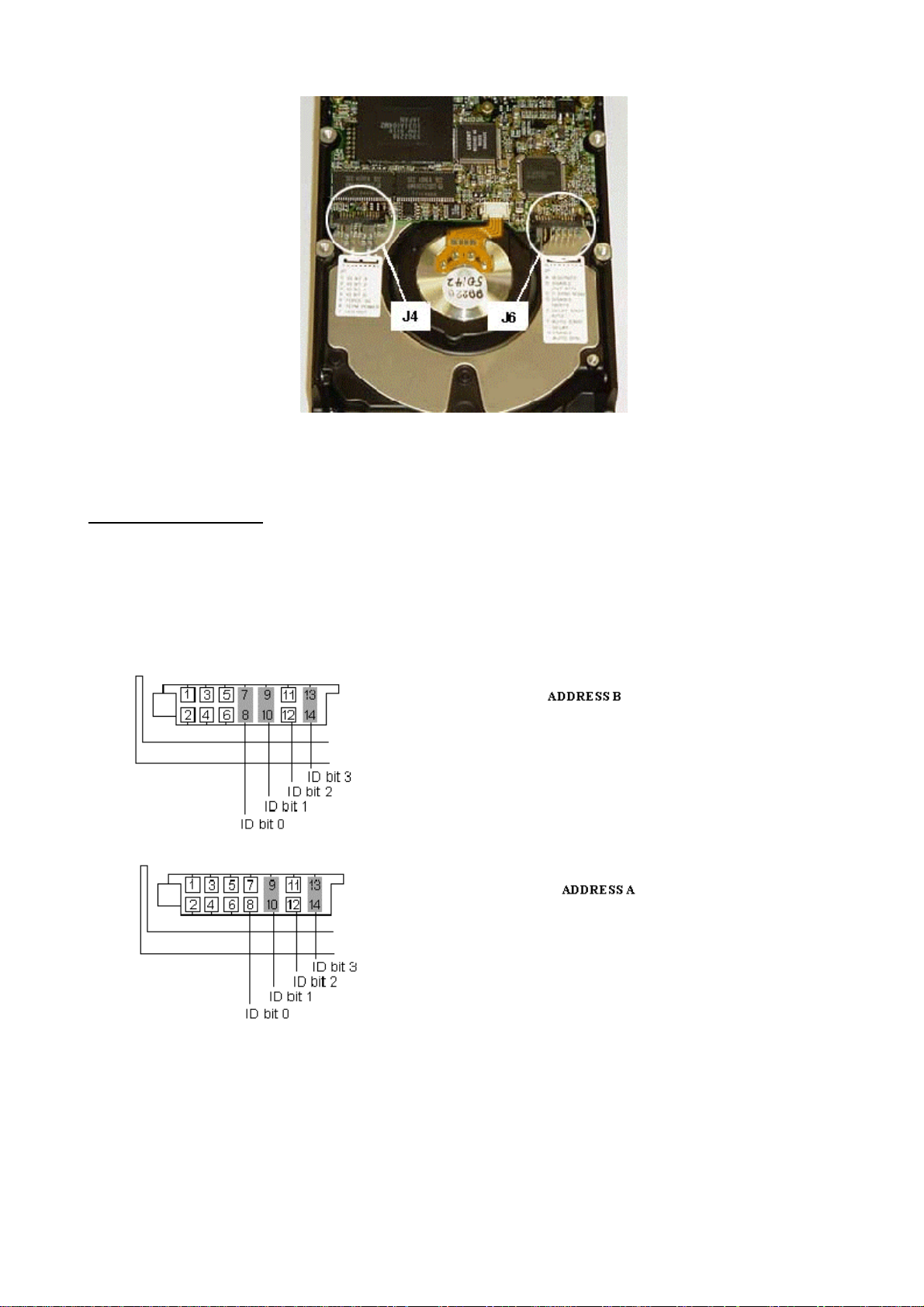
Section 6 Programmings
Use the disk as is and do NOT install the SCSI Narrow to Wide adapter.
J4 option jumper block:
Set the jumper settings of the SCSI.
Image disk B (11)
Additional image disk 1 A (10)
Additional image disk 2 9
Additional image disk 3 8
6-14 (a/03.1) EasyVision RAD R4
Copyright © 2003 Philips Medical Systems Germany
ALL RIGHTS RESERVED
Page 93

Programmings Section 6
J6 option jumper block:
Enable auto spin
4.7. IBM DMVS 9.1 GB (KIT: 4522 300 15063)
Applies to EasyVision based on Ultra 5, Ultra 10, Ultra 60.
The hard disk drive is factory installed in the Peripheral 2 cabinet.
EasyVision RAD R4 (a/03.1) 6-15
Copyright © 2003 Philips Medical Systems Germany
ALL RIGHTS RESERVED
Page 94

Section 6 Programmings
Use the disk as is and do NOT install the SCSI Narrow to Wide adapter.
The jumper settings of the SCSI.
SCSI address =B (11) Image disk
SCSI address =A (10) for 1
additional image disk.
SCSI address =9 for 2 additional
image disk.
SCSI address =8 for 3 additional
image disk.
4.8. IBM DRVS 9.1 GB (KIT: 4522 300 15062)
Applies to EasyVision based on Ultra 5, Ultra 10, Ultra 60.
The hard disk drive is factory installed in the Peripheral 2 cabinet
Use the disk as is and do NOT install the SCSI Narrow to Wide adapter.
The jumper settings of the SCSI.
SCSI address =B (11) Image disk
SCSI address =A (10) for 1
additional image disk.
SCSI address =9 for 2 additional
image disk.
SCSI address =8 for 3 additional
image disk.
4.9. IBM 4.5 GB / 9.1 GB (KIT: 4522 300 15061)
Applies to EasyVision based on Ultra 5, Ultra 10, Ultra 60 with external image disk.
The hard disk drive is factory installed in the Peripheral 2 or Peripheral 4 Cabinet
6-16 (a/03.1) EasyVision RAD R4
Copyright © 2003 Philips Medical Systems Germany
ALL RIGHTS RESERVED
Page 95

Programmings Section 6
Set the jumper settings of the SCSI.
SCSI address =B (11) Image disk
SCSI address =A (10) for 1 additional image disk.
SCSI address =9 for 2 additional image disk.
SCSI address =8 for 3 additional image disk.
Terminators resistors removed!
NOTE
________________
EasyVision RAD R4 (a/03.1) 6-17
Copyright © 2003 Philips Medical Systems Germany
ALL RIGHTS RESERVED
Page 96

Section 6 Programmings
5. FRAMEBUFFERS
5.1. D
OME MD
2
Jumper settings on the board:
J4: Position 1-2 (default): enables VGA
J5: Position 1-2 (always)
Use only VGA cables with 15 pin sub-D VGA connectors at both ends; cables with BNC connectors will not
work with Philips/FIMI monitors.
5.1.1. U
PGRADING AN ULTRA
5/10
When a Dome graphics board has been installed in the field the following commands must be entered to
activate the board.
• Go to the OK prompt.
• Enter setenv output-device /pci/DOME,Md2PCI
• Enter reset
Enter configuration program and configure the board. See chapter Framebuffer/ Monitor Settings in the
Release Bulletin.
If the DOME FRAMEBUFFER is removed and the Onboard frame buffer is used do the following:
• Go to the OK prompt.
• Enter setenv output-device screen
• Enter reset
Enter configuration program and configure the board. See chapter Framebuffer/ Monitor Settings in the
Release Bulletin.
6-18 (a/03.1) EasyVision RAD R4
Copyright © 2003 Philips Medical Systems Germany
ALL RIGHTS RESERVED
Page 97

Programmings Section 6
5.1.2. U
To install a DOME GreyScale FRAMEBUFFER in an Ultra 60 the following procedure must be done:
• Stop the application and shut the system down in a proper way.
• For Solaris 8 only: Do not remove the UPA TRUE COLOR FRAME BUFFER(s) and install the DOME
GreyScale FRAMEBUFFER.
• Connect the video cable to the DOME frame buffer board. The first frame buffer channel always has
the DOME logo displayed (the first frame buffer is the first VGA connector, which is located next to the
fixating bolt).
• Start the configuration and edit the EasyVision "Framebuffer / Monitor settings". Select automatic
configuration (the DOME FRAMEBUFFER should be selected) and leave this panel.
See chapter Framebuffer/ Monitor Settings in the Release Bulletin.
• Execute the configuration.
If the DOME frame buffer is removed and a UPA TRUE COLOR FRAMEBUFFER is used, the next sequence
of instructions must be executed:
• Stop the application and shut the system down in a proper way.
• Remove the DOME GreyScale FRAMEBUFFER and install the UPA TRUE COLOR
FRAMEBUFFER(s).
• Connect the video cable to the UPA TRUE COLOR FRAMEBUFFER.
• Start the configuration and edit the EasyVision "Framebuffer / Monitor settings". Select automatic
configuration and leave this panel. See chapter Framebuffer/ Monitor Settings in the Release
Bulletin.
• Execute the configuration.
5.2. SUN PGX F
PGRADING AN ULTRA
RAMEBUFFER
60
Applies to EasyVision based on Ultra 5 and Ultra 10.
The PGX card is usually factory installed in the Sun computer. In case of an upgrade:
• Install the board in the Sun computer.
• Set jumper settings as shown below.
• From the ok prompt boot the Sun with boot -r
EasyVision RAD R4 (a/03.1) 6-19
Copyright © 2003 Philips Medical Systems Germany
ALL RIGHTS RESERVED
Page 98

Section 6 Programmings
5.3. SUN C
EasyVision based on Ultra 10 and Ultra 60. There are no jumper settings.
REATOR
3D F
RAMEBUFFER
6-20 (a/03.1) EasyVision RAD R4
Copyright © 2003 Philips Medical Systems Germany
ALL RIGHTS RESERVED
Page 99

Programmings Section 6
6. HARDCOPY UNIT INTERFACE BOARD
The HCU board is usually factory installed in the Sun computer. In case of an upgrade:
• Install the board in the Sun computer.
• No jumper settings necessary.
• From the ok prompt boot the Sun with boot -r
EasyVision RAD R4 (a/03.1) 6-21
Copyright © 2003 Philips Medical Systems Germany
ALL RIGHTS RESERVED
Page 100

Section 6 Programmings
7. DMS READER INTERFACE BOARD
The DMS Reader interface board is usually factory installed in the Sun computer wh en ordered.
In case of an upgrade:
• Unpack the board and the DMS Reader cable.
• Ensure that the mains power supply to the EasyVision system has been switched off.
• Remove the cover of the EasyVision according to the EasyVision Sun Unit Manual, chapter Internal
Access.
• Insert the board into a suitable PCI slot and reassemble the computer
• Connect the DMS cable between the Sun and the Reader DMS connector.
• From the ok prompt boot the Sun with boot -r
• At the Start up Menu select Configuration go to the EasyVision RAD edit mode click on Peripheral
Settings and activate DMS Reader == Present.
• Execute the configuration.
6-22 (a/03.1) EasyVision RAD R4
Copyright © 2003 Philips Medical Systems Germany
ALL RIGHTS RESERVED
 Loading...