

Philips Dynalite DMC2 Installation Instructions Manual
DMC2
Dynalite Modular Controller (2 Output Modules)
Installation Instructions
Warning…………………………………………….. 2 Final Checks……………………..……………….. 6
Features…………………………………………….. 2 Dimensions…………….……………………….….. 7
Important Safeguards…………………………….. 2 Specications………………………………………. 8
Internal View……………………………………….. 3
Mounting…………………………………….……… 4
Module mounting…………………..……………… 5
DMC2 Installation Instructions Rev B Specications subject to change without notice
Dynalite manufactured by WMGD Pty Ltd (ABN 33 097 246 921) Unit 6, 691 Gardeners Road Mascot NSW 2020 Australia Tel: +61 2 8338 9899 Fax: +61 2 8338 9333
E-Mail: support.controls@philips.com Web: http://philips.com/dynalite

2
DMC2 Installation Instructions Rev 03
Features
• Two Control Module Locations
Wide range of interchangeable output modules
available to meet the capacity and control type
needs of any project.
Modules supplied separately.
The DMC2 is only compatible with Philips
Dynalite modules.
• Communication Module
Allows the controller to be used with a variety of
supported protocols.
• Convection Cooled
The DMC2 is ventilated, and requires no active
cooling system when installed in accordance with
these instructions.
• Multiple Control Options
The DMC2 is designed to operate as part of a
network system that can be structured to meet the
project’s needs.
• Simple Installation
The enclosure is suitable for both surface and
recess mount. Cabling knockouts for supply and
load cables are provided at the top, side and
back of the enclosure for supply and load cables.
Cabling knockouts for Control cables (Class 2 /
SELV) are located at the bottom of enclosure.
Important Safeguards
Read the Instructions – We recommend that you read
this document prior to commencement of installation. Do
not energize the DMC until all steps of the installation
procedure on page 6 are complete.
Installation of the home and building automation and
control system shall comply with HD60364-4-41 where
applicable.
Special Programming – Once assembled, powered
and terminated correctly, this device will operate in basic
mode. A new Philips Dynalite user interface on the same
network will turn all output lighting channels on from
button 1 and off from button 4 allowing testing of network
cables and terminations. Advanced functions and custom
presets can then be congured via the EnvisionProject
commissioning software.
If commissioning services are required, contact your local
distributor for details.
High Voltage Insulation Test – Do not Megger test any
circuitry connected to the dimming system, as damage to
the electronics may result.
Power Sources – This device should only be operated
from the type of supply specied on installed modules.
This device must be earthed.
Mounting Location – This device must be mounted
upright on a vertical surface (refer to page 4 for mounting
instructions), with a minimum clearance of 200mm on all
sides of the front cover.
Install in a dry, well-ventilated location.
Controllers may emit some audible noise such as
humming or relay chatter. Take this into account when
deciding the mounting location.
Data Cable – The recommended cable for connections
to the serial port is screened stranded RS485 compatible
CAT-5E data cable with three twisted pairs. Refer to the
installation instructions for the communication module for
more cabling information. This cable must be segregated
from mains and Class 1 cables as per local electrical
code. If anticipated cable runs are over 600 meters for
serial cables, consult your dealer for advice. Do not cut or
terminate live data cables.
Manual Override Keypad – The Manual Override Keypad
does not provide permanent isolation. Isolate at the supply
before performing work on load circuits.
3
DMC2 Installation Instructions Rev 03
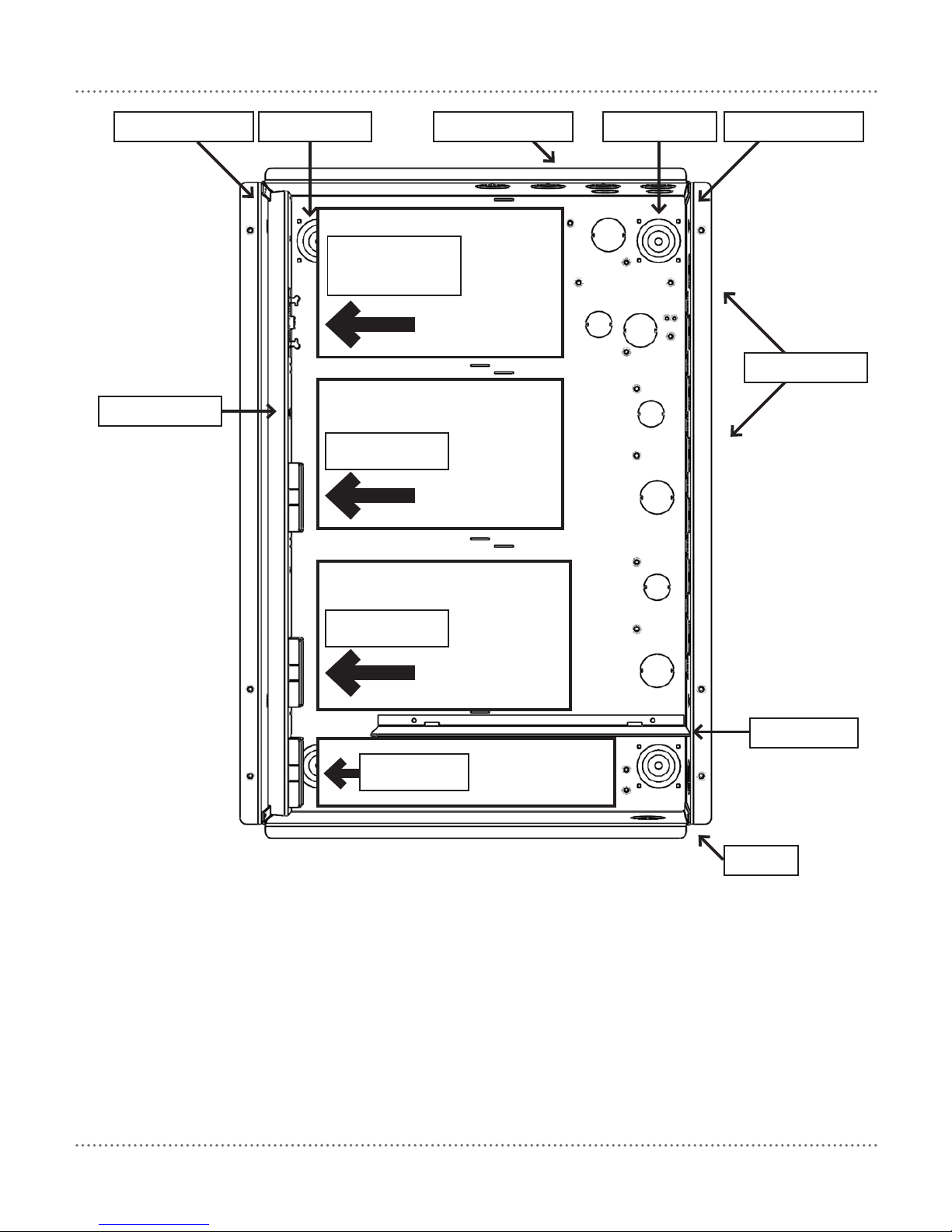
Internal View
Supply
module
install
location
Control
module 1
install
location
Control
module 2
install
location
Comms module
install location
Communication
bus and power
connection
Communication
bus connection
Communication
bus connection
Surface mounting sleeve
Wall mounting point
Knockouts for unit supply
Wall mounting point
Communication
bus cover
Knockouts for lighting
group channels
High voltage barrier
Data cable
entry points
Surface mounting sleeve
For spare parts, please call your nearest Philips Dynalite Customer Service Centre.
Communication
bus connection
 Loading...