

Philips DYNALITE DDRC1220FR-GL User Manual
DDRC1220FR-GL
To reduce the risk of re or electric shock, do not expose this device to rain or moisture. Installation, programming and maintenance must be
carried out by qualied personnel. All local wiring and electrical regulations must be followed when installing device.
Overview
• Single phase supply – One phase at 0.25 A
• 12 x feed-through outputs – Rated at 20 A
• Multiple wiring schemes supported – Controls Single Phase
and Neutral or Three Phase and Neutral (Star) wiring
• Powerful internal PLC – Custom scripts can provide process
control based on conditional logic
• DIN-rail mounting – 12 units wide
• Hardware override – Service override switch accessible from
front panel
12 x 20 A Relay Controller
Read Instructions – We recommend that you read this guide prior to
commencement of installation.
Manual Override Switches – These switches do not provide
permanent isolation. Isolate at the supply before performing work on
load circuits.
Special Programming – Once powered and terminated correctly
this device only operates in basic mode. Advanced functions are
commissioned via the Envision software. If commissioning services
are required, contact your local distributor.
Power Sources – This device should only be operated from the type
of supply specied on the front cover. This device must be earthed.
Feed-through output circuits – The load on a circuit should not
exceed the specied capacity of 20 A. Loads should be calculated to
ensure that the overall maximum capacity of 180 A is not exceeded.
This device should be fed via HRC fuse or MCB. Output circuits
are suitable for Single Phase or Three Phase Star (with Neutral)
only. Suitable for some Delta wiring installations, contact Distributor
Support for more information.
Mounting Location – Install in a dry, well-ventilated location. The
device may emit some mechanical noise during operation. Take this
into account when deciding the mounting location.
Data Cable – Use screened, stranded RS485 data cable with three
twisted pairs. Segregate from mains cables by at least 300 mm.
Connect devices in a ‘daisy chain’ conguration. A data cable that is
connected to an energized device is live. Do not cut or terminate live
data cables.
Installation – Installation must be done in accordance with local
wiring code (or wiring rules). Network topology for installation is Daisy
Chain. Installation of the home and building automation and control
system shall comply with HD60364-4-41.
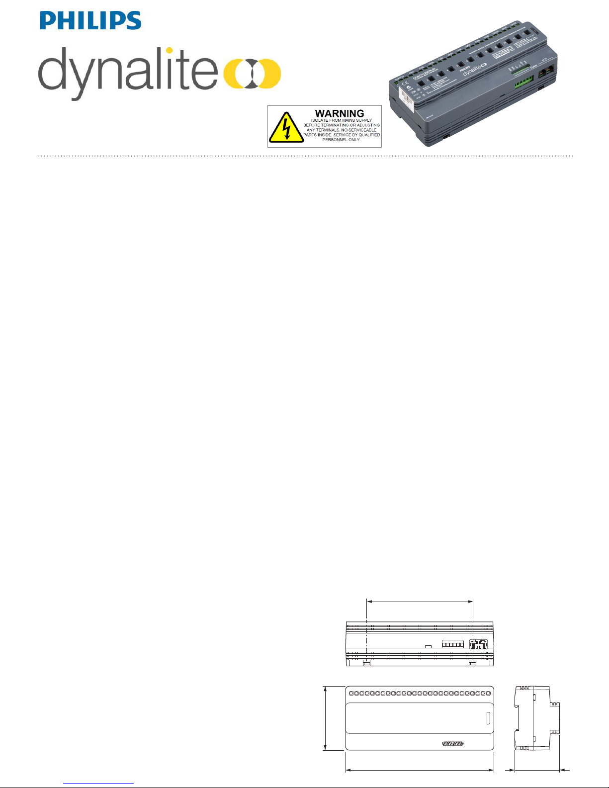
Hardware Dimensions
Installation Steps
1. Mount the device on a DIN-rail inside an approved enclosure, in
compliance with local electrical codes.
2. Calculate loads to ensure no channels are overloaded, then
connect loads to the output channels. The maximum loads are:
Per Channel: 20 A at 240 VAC (resistive).
Max inrush 500 A (200 uS)
Total Device Load: 180 A (resistive)
3. Connect supply and load cables to each channel. Supported
supplies and wiring schemes are:
Single phase 100-240 VAC, 3 phase 400/230 VAC star, and
100-120/208-240 VAC delta 50/60 Hz supply not exceeding
240 VAC phase-to-ground and across load supply terminals.
All live feeds must be protected with fuses / circuit breakers
rated 20 A or lower. Relay open contact rated voltage must not
exceed 240 VAC. Supply over-voltage (surge) must not exceed
4 kV, as per IEC category III classication.
4. Connect a single phase 0.25 A feed to the control circuit supply
terminals. This device must be earthed.
5. Connect data cables to the device as per the diagrams on the
next page.
6. If using the Auxiliary input, connect a dry contact device
in between the AUX and GND terminals. Keep cable runs
between the device and the dry contacts under ten meters and
use shielded twisted pair where possible. The function of the
Auxiliary input is congured during commissioning.
215 mm (8.5 in)
93 mm (3.6 in)
64 mm (2.5 in)
154 mm (6.1 in)
DDRC1220FR-GL Installation Instructions Rev 08 Specications subject to change without notice
Dynalite manufactured by WMGD Pty Ltd (ABN 33 097 246 921) Unit 6, 691 Gardeners Road Mascot NSW 2020 Australia Tel: +61 2 8338 9899 Fax: +61 2 8338 9333
E-Mail: support.controls@philips.com Web: www.philips.com/dynalite
Control Supply: 100-240 V 50/60 Hz single phase at 0.25 A, Over-voltage category III, maximum 4kV surge
Load Outputs: 12 x feed-through outputs at 20 A per channel, maximum total device load 180 A
1 Phase & Neutral, 3 Phase & Neutral Star. Some delta wiring supported.
Switching Device: Relay 50 A 230 VAC resistive (5000 VA lighting load rated), maximum 500 A (200 uS) inrush current
Supply Terminals: 1 x Phase, 1 x Neutral 1 x Earth, up to 5 mm2 cable per terminal
Load Terminals: 1 x Phase, 1 x Neutral 1 x Earth, up to 5 mm2 cable per terminal
User Controls: Service switch, Diagnostic LED
I/O: 1 x RS485 DyNet serial port
1 x AUX programmable dry contact input
DyNet DC Supply: 120 mA (capacity for approximately six panels)
Presets: 170
Programmable Logic: 8 tasks (most UPAN mnemonics supported)
Operating Conditions: Temperature: 0 to 50° C ambient, Humidity: 0 to 90% non-condensing
Storage & Transport: Temperature: -25 to 60° C ambient, Humidity: 0 to 90% non-condensing
Construction: Polycarbonate DIN-rail enclosure, (12 units wide), IP20, UL940-V0 rated
Dimensions: 93 mm x 215 mm x 64 mm (3.7” x 8.5” x 2.5”)
Weight: 0.76 kg
Certication: CE, RCM
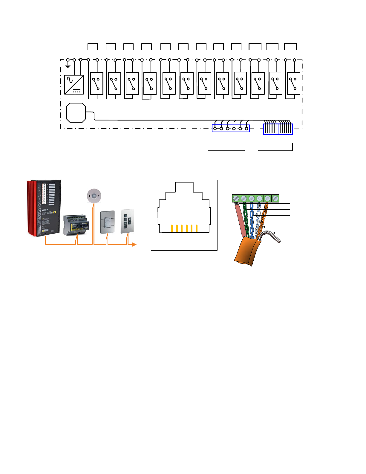
Recommended Cable Type
Dynalite DYNET-STP-CABLE or equivalent shielded
three twisted-pair.
See datasheet for more information.
Recommended Cable Color Coding
Green/White Pair Paralleled for GND
Orange/White Pair Paralleled for +12VDC
Blue/White Pair Blue for DATA+
White for DATA-
Brown/White Pair Spare, use for SHIELD on unshielded cables
SHLD
GND
D+
D-
+12V
Aux
Shield
Green/Green white
Blue
Blue white
Orange/Orange white
Brown/Brown white
+VE
+VE
D –
D +
GND
GND
RS485 DyNet network
Product Specications
Electrical Diagram
Supply:
100-240V
1 Phase
0.25A
E
µP
NLIN
OUT
CH1
CH2
CH3
CH4
+VE
D +
D -
GND
Shield
AUX
CH5
CH6
CH7
CH8 CH9
CH10 CH11
CH12
DyNet
RS485
2 x RJ12
IN
OUT
IN
OUT
IN
OUTINOUT
IN
OUTINOUT IN
OUTINOUT
IN
OUTINOUT IN
OUT
Data Cable Connection
 Loading...