

Page 1

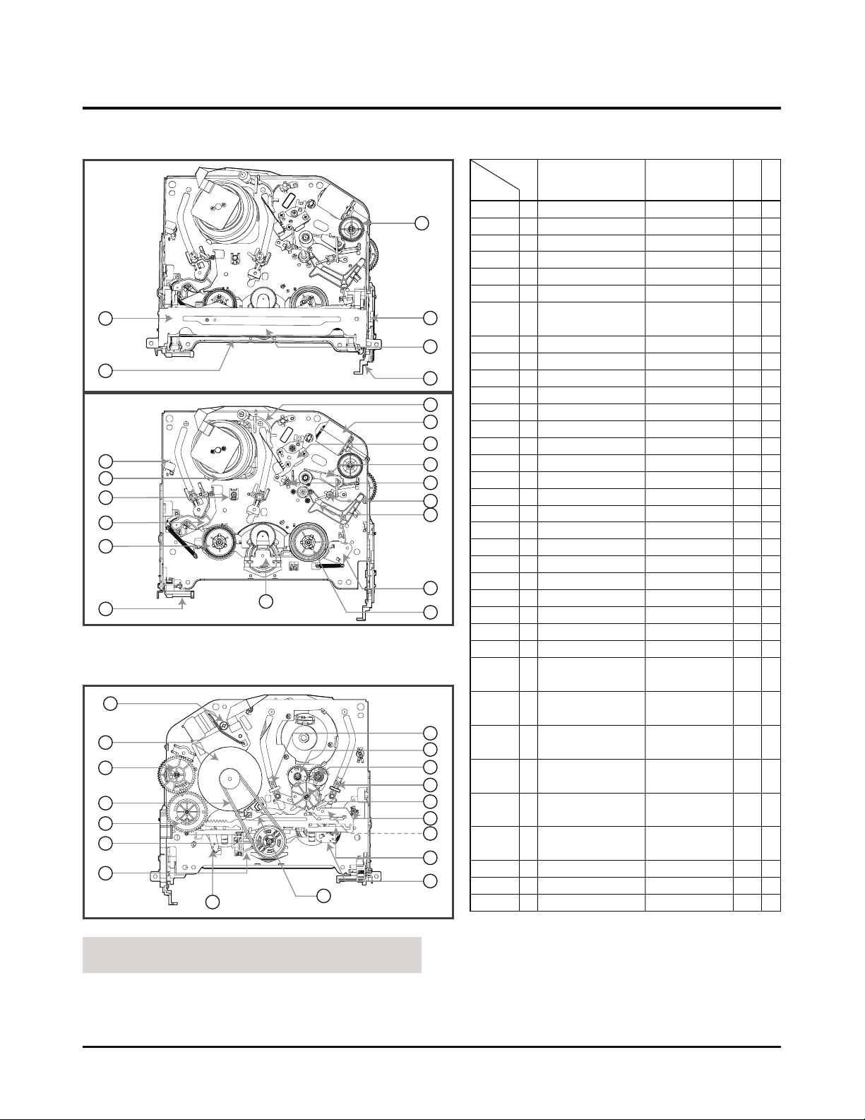
POSITION DRAWING OF DECK
MECHANISM PARTS
• Top View......................................................4-1
• Bottom View ...............................................4-1
DISASSEMBLY AND
ASSEMBLY OF DECK MECHANISM
01.Assembly and disassembly of Drum.........4-2
02.Plate Top disassembly ..............................4-4
03.Holder Assembly CST...............................4-4
04.Disassembly of Gear Assembly
Rack F/L ....................................................4-4
05.Opener Door .............................................4-4
06.Arm Assembly F/L.....................................4-4
07.Lever Assembly S/W.................................4-4
08.Motor Assembly L/D..................................4-5
09.Gear Wheel ...............................................4-5
10.Arm Assembly Cleaner..............................4-5
11. Head F/E ...................................................4-5
12.Base Assembly A/C Head.........................4-5
13.Brake Assembly T .....................................4-6
14.Arm Assembly Tension..............................4-6
15.Reel S / Reel T..........................................4-6
16.Base Assembly P4 ....................................4-7
17.Opener Lid ................................................4-7
18.Arm Assembly Pinch .................................4-7
19.Arm T/up ...................................................4-7
20.Supporter, Capstan ...................................4-8
21.Belt Capstan/Motor Capstan .....................4-8
22.Lever F/R ..................................................4-8
23.Clutch Assembly D37................................4-8
24.Gear Drive/Gear Cam ...............................4-9
25.Gear Sector...............................................4-9
26.Brake Assembly Capstan..........................4-9
27.Plate Slider................................................4-9
28.Lever Tension ............................................4-9
29.Lever Spring..............................................4-9
30. Lever Brake..............................................4-9
31.Gear Assembly P2/Gear Assembly P3 ...4-10
32.Base Assembly P2/Base Assembly P3...4-10
33.Base Loading ..........................................4-10
34.Base Tension ...........................................4-11
35.Arm Assembly Idler Jog ..........................4-11
DECK MECHANISM ADJUSTMENT
• Fixtures and tools for service ................4-12
1. Check of Mechanism Assembly Mode ....4-13
2. Previous Preparation for
Deck Adjustment .....................................4-14
3. Torque Measuring ...................................4-14
4. Adjustment of Guide Roller Height..........4-15
4-1. Prior Adjustment...............................4-15
4-2. Fine Adjustment ...............................4-15
5. Adjustment of Audio/Control (A/C) Head..4-16
5-1. Prior Adjustment...............................4-16
5-2. Check of Tape Path between Pinch
Roller and Take-up Guide ................4-17
5-3. Fine Adjustment
(Azimuth Adjustment).......................4-17
6. X-distance Adjustment ............................4-17
7. Adjustment of Drum Assembly
(Video Heads) .........................................4-18
8. Tachometer Adjustment of
Deck Assembly........................................4-18
8-1. Check of Audio, RF Normalization
Time (Locking Time) in Play after
CUE or REV.....................................4-18
8-2. Check of Tape Curl and
Jam Status .......................................4-18
MAINTENANCE AND CHECK OF
VIDEO FUNCTION
1. Checking Points before Repair ...............4-19
2. Essential Check and Maintenance..........4-20
3. Regular Check and Maintenance............4-20
4. Tools for Check and Maintenance...........4-20
5. Maintenance Course ...............................4-20
5-1. Removal of Foreign Materials..........4-20
5-2. Grease Application...........................4-21
GUIDE FOR TROUBLESHOOTING
1. Deck Mechanism.....................................4-23
2. Front Loading Mechanism.......................4-26
EXPLODED VIEWS
1. Front Loading Mechanism Section...........4-28
2. Moving Mechanism Section(1).................4-29
3. Moving Mechanism Section(2).................4-30
SECTION 4 MECHANISM (D-37) OF VCR PART
CONTENTS
Page 2
POSITION DRAWING OF DECK MECHANISM PARTS
4-1
5
4
3
2
6
9
10
8
12
18
16
19
17
13
15
11
1
33
14
7
15
35
• Top View
• Bottom View
21
21
24
23
22
31
32
31
32
25
34
28
27
29
20
26
30
24
1 Drum Assembly 3 screws A-1 T
2 Plate Top 2 hooks A-2 T
2 3 Holder Assembly CST 6 chasses A-2 T
2,3 4 Gear Assembly Rack F/L 1 hook A-2 T
2,3,4 5 Opener Door Chassis Hole A-2 T
2,3,4,5 6 Arm Assembly F/L Chassis Hole A-2 T
7 Lever Assembly S/W Chassis Hole, A-2 T
1 hook
8 Motor Assembly L/D 1 screw A-3 T
9 Gear Wheel 2 hooks A-3 T
10 Arm Assembly Cleaner Chassis Embossing A-3 T
11 Head F/E Chassis Embossing A-3 T
12 Base Assembly A/C Head 1 screw A-3 T
2,3 13 Brake Assembly T 1 hook A-4 T
2,3 14 Arm Assembly Tension 1 hook A-4 T
2,3,13,14 15 Reel S / Reel T Shaft A-4 T
16 Base Assembly P4 Chassis Embossing A-5 T
17 Opener Lid Chassis Embossing A-5 T
17 18 Arm Assembly Pinch Shaft A-5 T
17 19 Arm T/up 1 hook A-5 T
20 Supporter, capstan Chassis Hole A-6 B
17,18 21 Belt Capstan/Motor Capstan 3 screws A-6 B
22 Lever F/R Locking Tab A-6 B
21, 22 23 Clutch Assembly D37 Washer A-6 B
24 Gear Drive/Gear Cam Washer/Hook A-7 B
25 Gear Sector Hook A-7 B
21 26 Brake Assembly Capstan Chassis Hole A-7 B
21,22,23, 27 Plate Slider Chassis Guide A-7 B
24,2526
21,22,23, 28 Lever Tension 1 Hook A7 B
24,2526,27
21,22,23, 29 Lever Spring 1 Hook A-7 B
24,2526,27
21,22,23, 30 Lever Brake 1 Hook A-7 B
24,2526,27
25 31 Gear Assembly P2/ Bass A-8 B
Gear Assembly P3
2, 3, 14, 32 Base Assembly P2 6 Chasses A-8 B
25, 31 /Base Assembly P3
25, 31 33 Base Loading 3 Hooks A-8 B
2,3,14 34 Base Tension Chassis Embossing A-9 T
35 Arm Assembly Idler Jog Locking Tab A-9 T
Parts firstly
Disassembled
Order Of Dis-
assembled
Part Fixing Type
Ref.
Draw-
ings
Posi
tion
NOTE : Assembly order is a reverse of
disassembly order.
(1) For assembly, check the assembly mode is accurate.
(2) Parts firstly disassembled indicate parts firstly disassem-
bled in disassembly of related parts.
T:Top, B:Bottom
Page 3
DISASSEMBLY AND ASSEMBLY OF DECK MECHANISM
Cap, FPC
Drum Assembly
Cable Flat
(S1)
(S1)
(S1)
Holder FPC
H1
H2
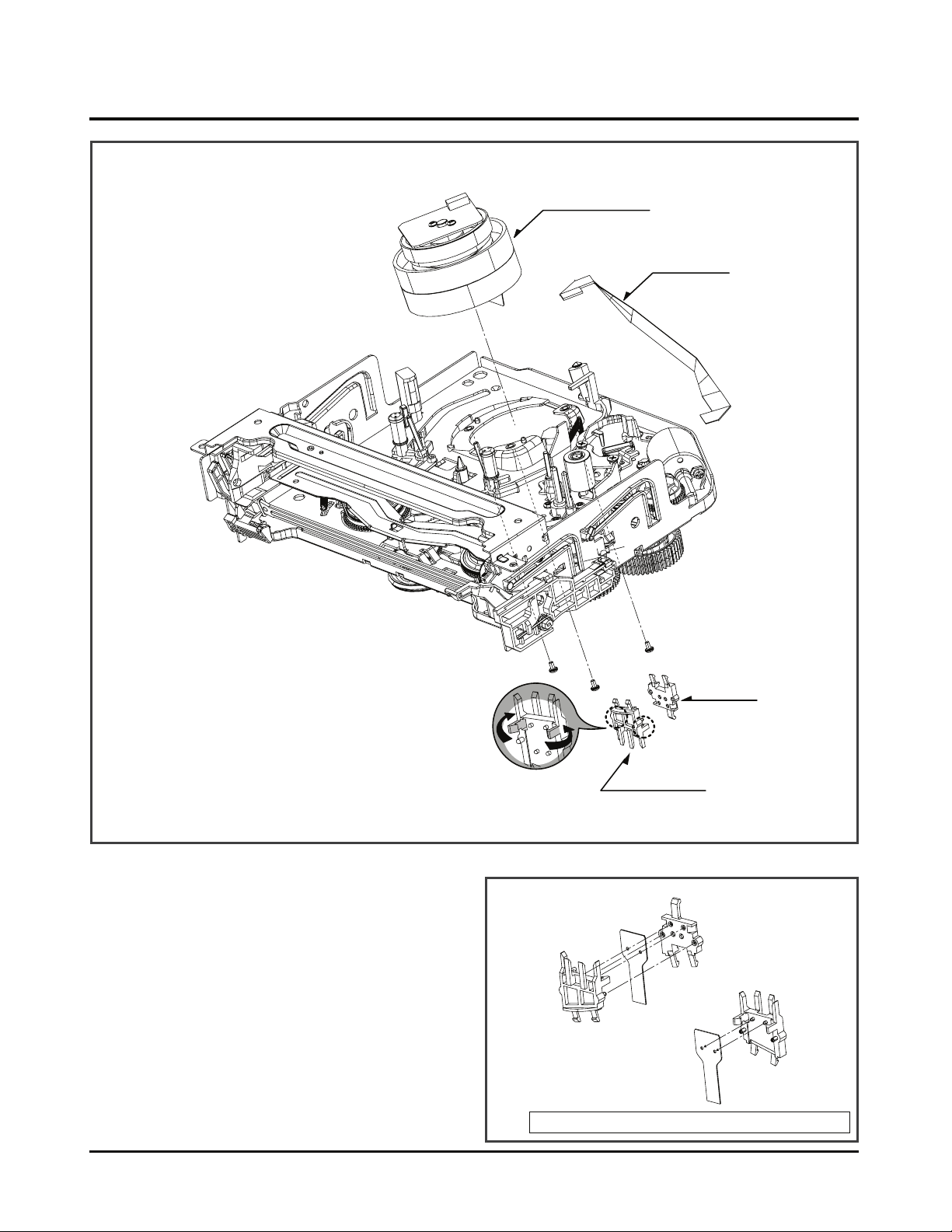
1. Disassembly of Drum Assembly
(Figure A-1)
1) Separate cable flat from the Drum FPC and the Capstan
Motor.
2) Release 3 screws (S1) on the bottom side of the chassis,
and separate the drum assembly.
3) Release the hooks (H1, H2) and separate both the holder
FPC and the Cap FPC (disassemble if necessary).
Fig. A-1
Cautions in assembly of FPC
Holder FPC
Drum FPC
Cap FPC
Assembly shape seen in the reverse direction
(Fig. A-1-1)
4-2
Page 4
DISASSEMBLY AND ASSEMBLY OF DECK MECHANISM
(B)
(E)
(C)
Plate Top
Arm Assembly F/L
Gear Assembly Rack F/L
Opener Door
Holder Assembly CST
(B')
(H3)
(A)
(B)
Lever Assembly S/W
(H4)
(E)
Fig. A-2
(Fig. A-2-1)
(Fig. A-2-2)
(Fig. A-2-5)
(Fig. A-2-6)
(Fig. A-2-3)
(Fig. A-2-4)
4-3
Page 5
DISASSEMBLY AND ASSEMBLY OF DECK MECHANISM
(B')
(C')
(C)
(B)
(D)
Holder Assembly CST
Chassis
Chassis
(H4)
Gear Rack F/L
Gear Drive
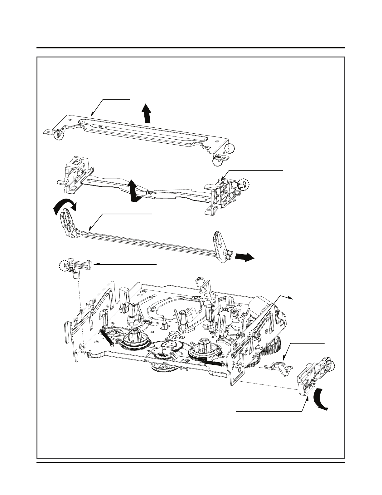
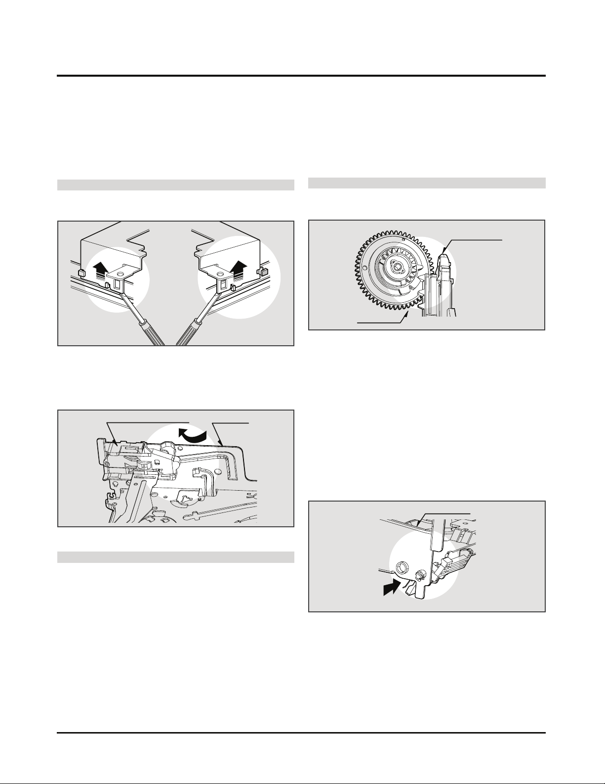
2. Disassembly of Plate Top (Fig. A-2-1)
1) Separate the right part while leaning back the (B) part of
the plate top toward the arrow direction.
2) Separate the left part while leaning back the (B’) part of
the plate top toward the arrow direction.
(Tool used: Tool such as (-) driver, auger, etc with pointed or flat end)
CAUTIONS
Assemble while pressing the (C), (C’) part after corresponding them as in drawing.
3. Holder Assembly CST (Fig. A-2-2)
1) Firstly separate the left part from the groove on the (D)
part of chassis while moving the holder assembly CST
toward the arrow direction.
4. Disassembly of Gear Assembly
Rack F/L (Fig. A-2-3)
1) Separate the hook (H3) while leaning ahead the hook (3)
after moving the gear assembly rack F/L toward the arrow
(A) direction.
2) Separate the gear assembly rack F/L toward the arrow (B)
direction.
CAUTIONS
For the assembly, correspond the gear part of gear assembly rack F/L to the gear drive.
5. Opener Door (Fig. A-2-4)
1) Separate the opener door ahead from the guide hole of
chassis while turning it clockwise.
6. Arm Assembly F/L (Fig. A-2-5)
1) Firstly separate the left part of the arm assembly F/L from
the groove of chassis while pushing the arm assembly F/L
toward the arrow direction.
2) Separate the right part from the groove of chassis.).
7. Lever Assembly S/W (Fig. A-2-6)
1) Separate the lever assembly S/W while pushing it toward
the arrow direction after removing the hook (4) on the left
side of chassis.
2) Separate the right part from each groove of chassis
CAUTIONS
Assemble by inserting the left part after firstly inserting the
(E) part of the holder assembly CST into the groove on the
(E’) part of chassis.
4-4
Page 6
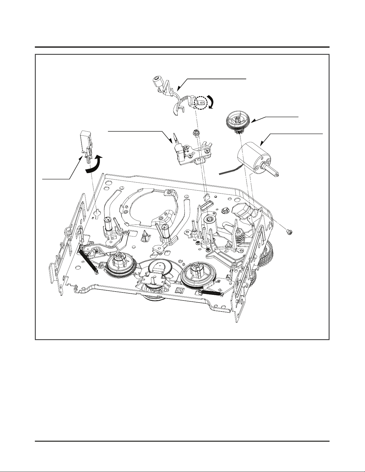
DISASSEMBLY AND ASSEMBLY OF DECK MECHANISM
Arm Assembly Cleaner
Motor Assembly L/D
Gear Wheel
Base Assembly A/C Head
(S4)
(S5)
Head F/E
(A)
(C1)
(H5)
(A)
Fig. A-3
(Fig. A-3-3)
(Fig. A-3-5)
(Fig. A-3-4)
(Fig. A-3-2)
(Fig. A-3-1)
8. Motor Assembly L/D (Fig. A-3-1)
1) Take the connector (C1) connected to the Capstan motor
PCB out.
2) Remove a screw (S4) of the chassis (S4) and step backward, and disassemble it while holding it up.
9. Gear Wheel (Fig. A-3-2)
1) Release the hook (H5) of the gear wheel and disassemble
it upward.
4-5
10. Arm Assembly Cleaner (Fig. A-3-3)
1) Separate the (A) part of Fig. A-3-1 from the embossing of
chassis, and hold it up while turning it anti-clockwise.
11. Head F/E (Fig. A-3-4)
1) Separate the (A) part of the head F/E from the embossing of chassis, and hold it up while turning it anti-clockwise.
12. Base Assembly A/C Head (Fig. A-3-5)
1) Release a screw (S5) and disassemble while holding it up.
Page 7
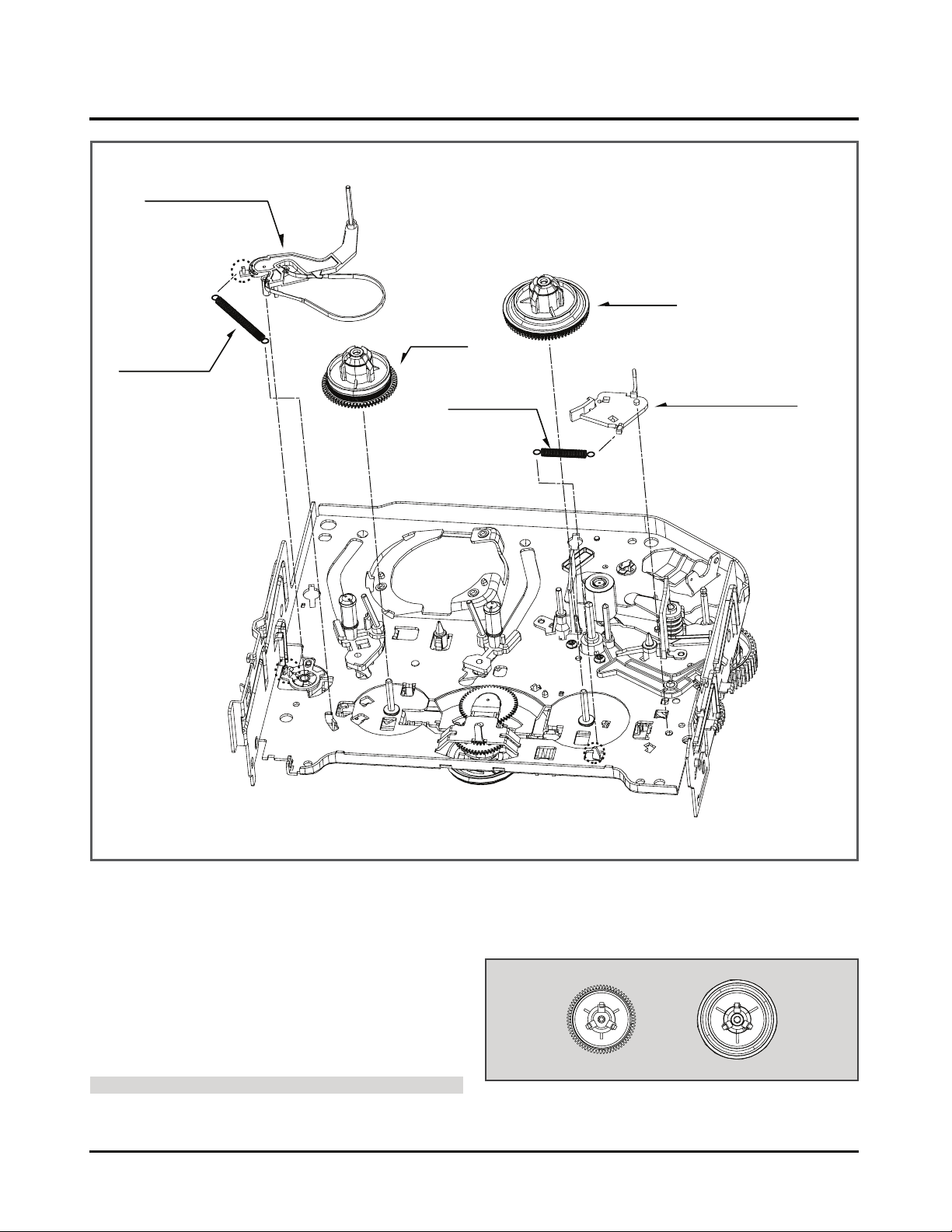
DISASSEMBLY AND ASSEMBLY OF DECK MECHANISM
Brake Assembly T
Reel T
Spring Tension
Arm Assembly Tension
Spring Tension
Reel S
(H7)
(H8)
(H6)
Fig. A-4
13. Brake Assembly T (Fig. A-4-1)
1) Release the spring tension from the lever spring hook
(H6).
2) Disassemble the brake assembly T while holding it
upward.
14. Arm Assembly Tension (Fig. A-4-2)
1) Release the spring tension the hook (H7) from the arm
assembly tension.
2) After releasing the hook (H8) of the base tension, separate it while holding it up.
CAUTIONS
Spring used for both brake assembly T and arm assembly
tension is used (2EA used).
15. Reel S/Reel T (Fig. A-4-3)
1) Disassemble the reel S/ reel T while holding it up (comparison between Reel S and Reel T)
Reel S Reel T
(Fig. A-4-3)
(Fig. A-4-2)
(Fig. A-4-1)
(Fig. A-4-3)
4-6
Page 8
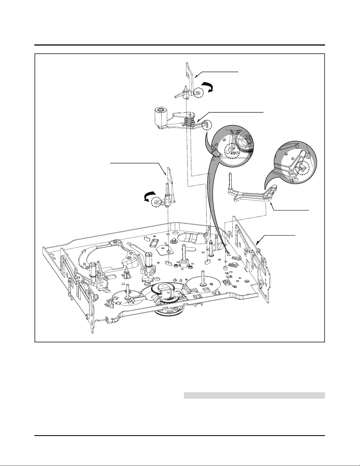
DISASSEMBLY AND ASSEMBLY OF DECK MECHANISM
Opener Lid
Arm Assembly Pinch
Base Assembly P4
Arm T/up
(A)
(B)
(C)
Chassis
(C)
(H9)
Fig. A-5
16. Base Assembly P4 (Fig. A-5-1)
1) Release the (A) part of the base assembly P4 from the
embossing of chassis.
2) Hold the base assembly P4 up while turning it anti-clockwise.
17. Opener Lid (Fig. A-5-2)
1) Release the (B) part of the opener lid from the embossing
of chassis.
2) Disassemble the opener lid upward while turning it anticlockwise.
18. Arm Assembly Pinch (Fig. A-5-3))
1) Hold the arm assembly pinch up.
19. Arm T/up (Fig. A-5-4)
1) Turn the arm T/up to release the anchor jaw (H9) part of
chassis and then hold it upward.
CAUTIONS
For the assembly, check the (C) part of the arm assembly
pinch is assembled as in drawing.
- REVERSE THE MECHANISM.
(Fig. A-5-2)
(Fig. A-5-1)
(Fig. A-5-3)
(Fig. A-5-4)
4-7
Page 9
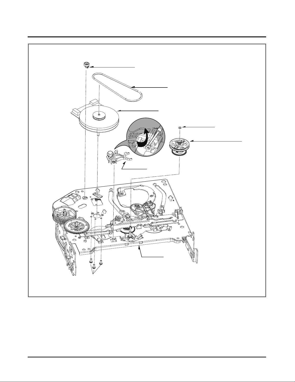
4-8
DISASSEMBLY AND ASSEMBLY OF DECK MECHANISM
Chassis
(S6)
Belt Capstan
Motor Capstan
Washer(W1)
Lever F/R
Clutch Assembly D37
(L1)
(L1)
Suppoter Capstan
Fig. A-6
20. Supporter, Capstan (Fig. A-6-1)
1) Turn the supporter and Capstan by 90 deg. clockwise
with a driver for disassembly.
21. Belt Capstan (Fig. A-6-2) /
Motor Capstan (Fig. A-6-3)
1) Separate the belt Capstan.
2) Undo 3 screws (S6) on the bottom side of chassis and disassemble it upward.
22. Lever F/R (Fig. A-6-4)
1) Release the locking tab (L1) and then disassemble it
upward.
23. Clutch Assembly D37 (Fig. A-6-5)
1) Remove the washer (W1) and then disassemble it
upward.
(Fig. A-6-1)
(Fig. A-6-2)
(Fig. A-6-3)
(Fig. A-6-4)
(Fig. A-6-5)
Page 10
DISASSEMBLY AND ASSEMBLY OF DECK MECHANISM
Gear Drive
Washer (W2)
Gear Cam
Plate Slider
Lever Tension
Lever spring
Base Loading
Gear Sector
(B)
(A)
(H10)
(W2)
(L2)
(H11)
Chassis
Gear Cam Hole(C)
Gear Cam Hole(B)
Gear Drive Hole(A)
Brake Assembly Capstan
Lever Brack
Fig. A-7
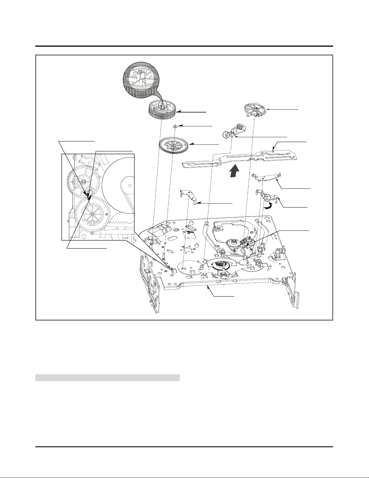
24. Gear Drive (Fig. A-7-1)/
Gear Cam (Fig. A-7-2)
1) Remove the washer (W2) and then disassemble the
gear drive.
2) Release the hook (H10) of the gear cam and then disas-
semble it upward.
CAUTIONS
For the assembly, adjust both the gear driver hole (A) and
the gear cam hole (B) straightly and then correspond the
gear cam hole (C) to the chassis hole.
25. Gear Sector (Fig. A-7-3)
1) Release the hook (H11) of the gear sector and then hold
the gear sector upward.
26. Brake Assembly Capstan (Fig. A-7-4)
1) Release the locking tab (L2) on the bottom side of the
plate slider and then disassemble it upward.
27. Plate Slider (Fig. A-7-5)
1) Disassemble the plate slider while holding it up.
28. Lever Tension (Fig. A-7-6)
1) Release the lever tension from the guide (A) of chassis
while turning it anti-clockwise.
2) Disassemble the lever tension while holding it up.
29. Lever Spring (Fig. A-7-7)
1) Release the (B) part of the lever spring from the guide
(A) of chassis while turning it anti-clockwise.
2) Disassemble the lever tension while holding it up.
30. Lever Brake (Fig. A-7-8)
1) Disassemble the lever brake while holding it up.
(Fig. A-7-4)
(Fig. A-7-5)
(Fig. A-7-8)
(Fig. A-7-7)
(Fig. A-7-6)
(Fig. A-7-1)
(Fig. A-7-2)
(Fig. A-7-3)
4-9
Page 11
4-10
DECK MECHANISM DISASSEMBLY
Gear Assembly P3
Gear Assembly P2
Base Assembly P2
Base Assembly P3
(A)
(B)
(H14)
(H12)
(H13)
Chassis
Gear assembly P2 Hole
Gear assembly P3 Hole
Lever Tension Boss
Plate slider Hole(B)
Base Loading
Fig. A-8
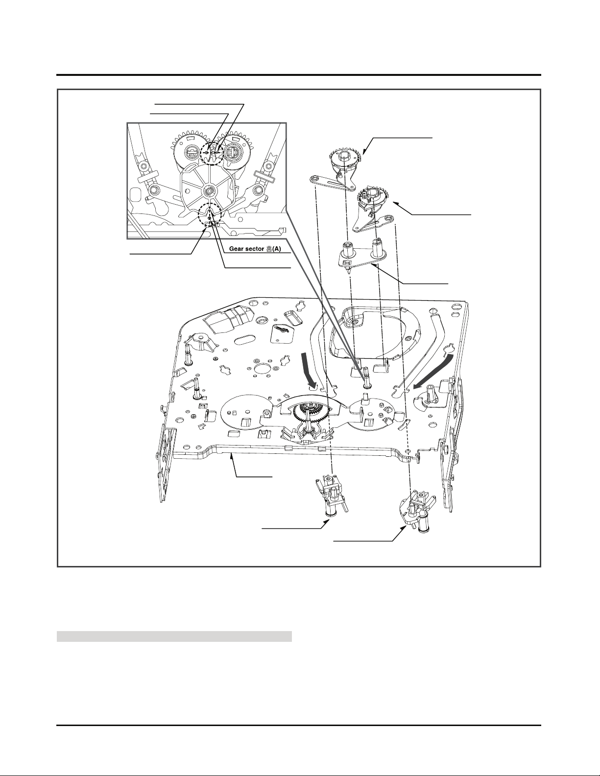
31. Gear Assembly P2 (Fig. A-8-1)/
Gear Assembly P3 (Fig. A-8-2)
1) Hold the gear assembly P2 upward.
2) Hold the gear assembly P3 upward.
CAUTIONS
For the assembly, check the holes of both the gear assembly P2 and the P3 are adjusted straightly, and then correspond the gear section groove (A) to the plate slider hole (B).
32. Base Assembly P2 (Fig. A-8-3)/
Base Assembly P3 (Fig. A-8-4)
1) Disassemble the base assembly P2 downward while mov-
ing it toward the arrow (A) direction along with the guide
hole of chassis.
2) Disassemble the base assembly P2 downward while mov-
ing it toward the arrow (B) direction along with the guide
hole of chassis.
33. Base Loading (Fig. A-8-5)
1) Release 3 hooks (H12, 13, 14) of the base loading, and
then disassemble them upward.
- Reverse the mechanism.
(Fig. A-8-1)
(Fig. A-8-2)
(Fig. A-8-5)
(Fig. A-8-4)
(Fig. A-8-3)
Page 12
DISASSEMBLY AND ASSEMBLY OF DECK MECHANISM
4-11
(A)
(B) (C)
Arm Assembly Idler Jog
Base Tension
Chassis
(D)
Fig. A-9
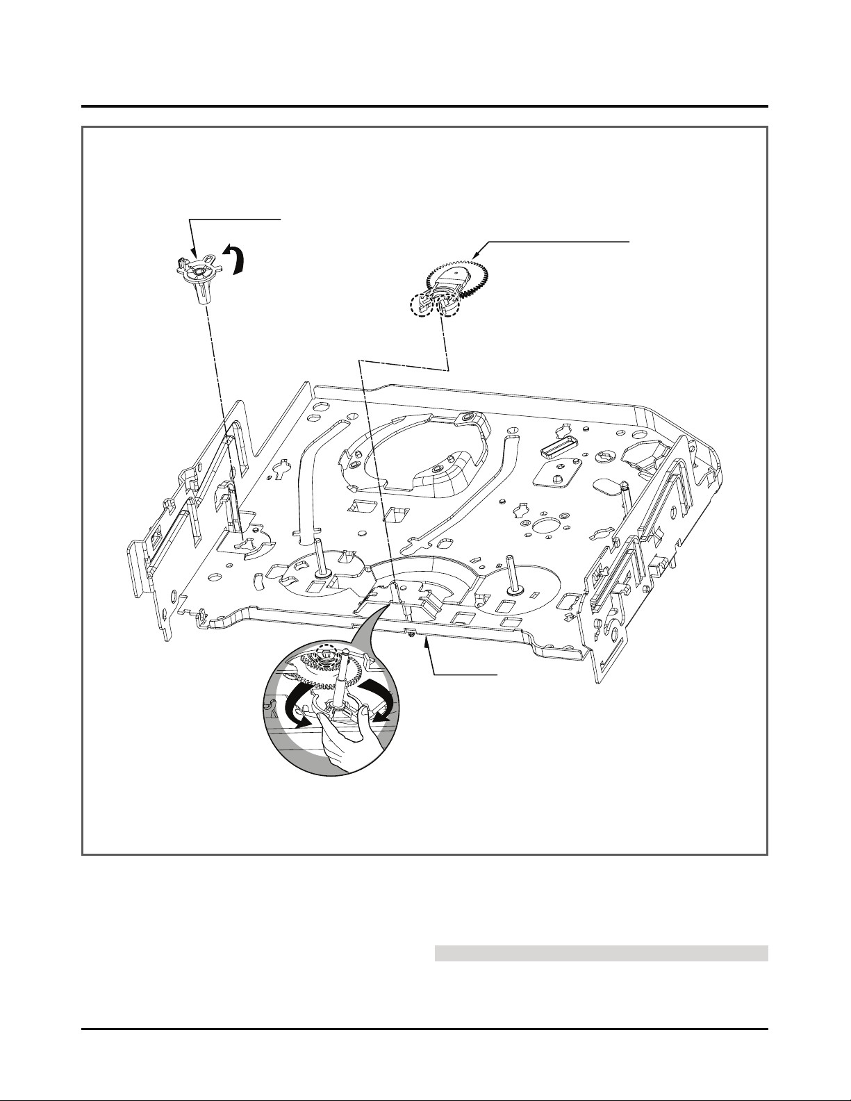
34. Base Tension (Fig. A-9-1)
1) Release the (A) part of the base tension from the
embossing of chassis.
2) Hold the base tension upward while turning it anti-clockwise.
35. Arm assembly Idler Jog (Fig. A-9-2)
1) Push both (B), (C) parts in Fig. A-9-2 toward the arrow
direction.
2) Disassemble the arm assembly idler upward.
CAUTIONS
Take care to ensure that the (D) part in the drawing is not
hung to chassis in disassembly.
(Fig. A-9-1)
(Fig. A-9-2)
Page 13
DECK MECHANISM ADJUSTMENT
SRK
VIDEO
CASSETTE
TORQUE
METER
VHT-303
S
R
K
-
V
H
T
-
S
S
R
K
-
V
H
T
T
300
250
200
150
50
0
300
250
200
150
50
0
100
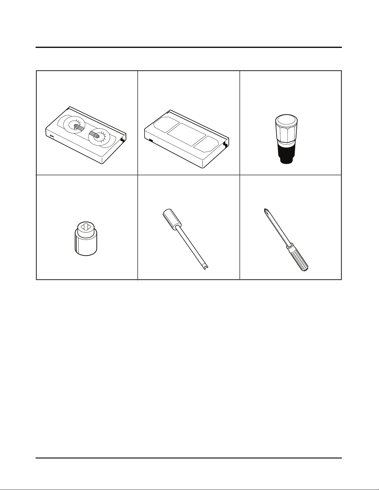
• Fixtures and Tools for Service
1. Cassette Torque Meter
SRK-VHT-303(Not SVC part)
Part No:D00-D006
4. Torque gauge adaptor
Part No:D09-R001
2. Alignment tape
Part No NTSC:DTN-0001
PAL:DTN-0002
5. Post height adjusting driver
Part No:DTL-0005
3. Torque gauge
600g.Cm ATG
Part No:D00-D002
6. + Type driver (ø5)
4-12
Page 14
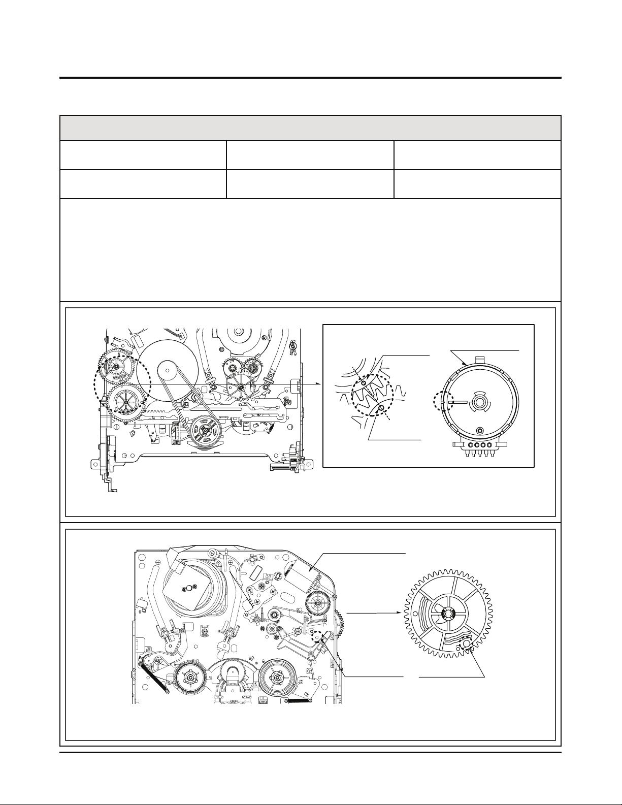
Purpose of adjustment : To make tools normally operate by positioning tools accurately.
DECK MECHANISM ADJUSTMENT
4-13
1) Turn the VCR on and take the tape out by pressing the
eject button.
2) Separate both top cover and plate top, and check both
the hole (A) of gear cam and the hole (A’) of chassis correspond (Fig. C-2).
3) If it is done as in the paragraph 2): Turn the gear cam as
in No.2) after mantling the motor assembly L/D.
4) Undo the screw fixing the deck and the main frame, and
separate the deck assembly. Check both the hole (A) of
gear cam and the hole (A’) of chassis correspond (Fig.
C-1).
5) Check the mode S/W on the main P.C. board locates at
a proper position as in (B) of the Fig. (C-1).
6) Connect the deck to the main P.C. board and perform all
types of test.
Gear Cam
Gear Drive
(C)
Mode S/W
(B)
Motor Assembly L/D
Gear Cam
Chassis Hole
Gear Cam Hole
(A)
(A')
Fixtures and tools used VCR (VCP) status Checking Position
• Blank Tape (empty tape)
• Eject Mode
(with cassette withdrawn)
• Mechanism and Mode Switch
Fig. C-1
Fig. C-2
CHECK DIAGRAM
BOTTOM VIEW
TOP VIEW
Correspondence of the gear cam hole (O)
and the gear drive hole (O)
1. Mechanism Assembly Mode Check
Page 15
DECK MECHANISM ADJUSTMENT
SRK
VIDEO
CASSETTE
TORQUE
METER
VHT-303
S
R
K
-
V
H
T
-
S
S
R
K
-
V
H
T
T
300
250
200
150
50
0
300
250
200
150
50
0
100
Fig. C-3-2Fig. C-3-1
Torque Gauge
Torque Gauge
Adaptor
Reel Table
Item
Fast forward Torque
Rewind Torque
Play Take-Up Torque
Review Torque
Fast Forward
Rewind
Play
Review
Torque Gauge
Torque Gauge
VHT-303
VHT-303
Take-Up Reel
Supply Reel
Take-Up Reel
Supply Reel
More than 400g°cm
More than 400g°cm
40~100g°cm
120~210g°cm
Mode Instruments Reel Measured Measuring Value
• Cassette Torque Meter (SRK-VHT-303)• Torque Gauge (600g.cm ATG)
VCR (VCP) status Measuring methodFixtures and tools used
2. Previous Preparation for Deck Adjustment
(Preparation to load the VCR (VCP) with cassette tape not inserted)
1) Take the power cord from the consent.
2) Separate the top cover and the plate assembly top.
3) Insert the power cord into again.
4) Turn the VCR (VCP) on and load the cassette while pushing the lever stopper of the holder assembly CST backward. In this case, clog both holes on the housing
rail part of chassis to prevent detection of the end sensor.
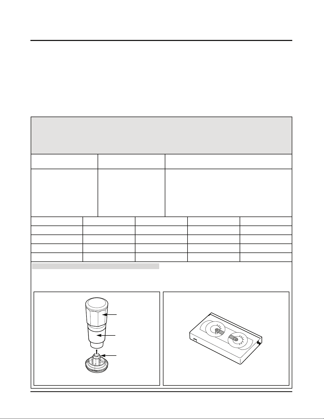
3. Torque Measuring
Purpose of Measuring : To measure and check the reel torque on the take-up part and the
supply part that performs basic operation of the VCR (VCP) for
smoothly forwarding the tape.
Measure and check followings when the tape is not smoothly
wound or the tape velocity is abnormally proceeded:
If doing so, proceeding to the stop mode is done. In this
status, input signals of all modes can be received.
However, operation of the Rewind and the Review is
impossible since the take-up reel remains at stop status
and so cannot detect the reel pulse (however, possible for
several seconds).
• Torque Gauge
(600 g.cm ATG)
• Torque Gauge Adaptor
• Cassette Torque Meter
SRK-VHT-303
• Play (FF) or Review
(REW) Mode
• Try to operate the VCR (VCP) per mode with the
tape not inserted (See ‘2. Prior Preparation for
Deck Adjustment).
• Measure after adhering and fixing the torque
gauge adaptor to the torque gauge (Fig. C-3-1)
• Read scale of the supply or take-up part of the
cassette torque meter (Fig. C-3-2).
NOTE
Adhere the torque gauge adaptor to the torque gauge for measuring the value.
4-14
Page 16
DECK MECHANISM ADJUSTMENT
Fig. C-4-1
GUIDE ROLLER
HEIGHT
ADJUSTMENT SCREW
ADJUSTMENT DIAGRAM
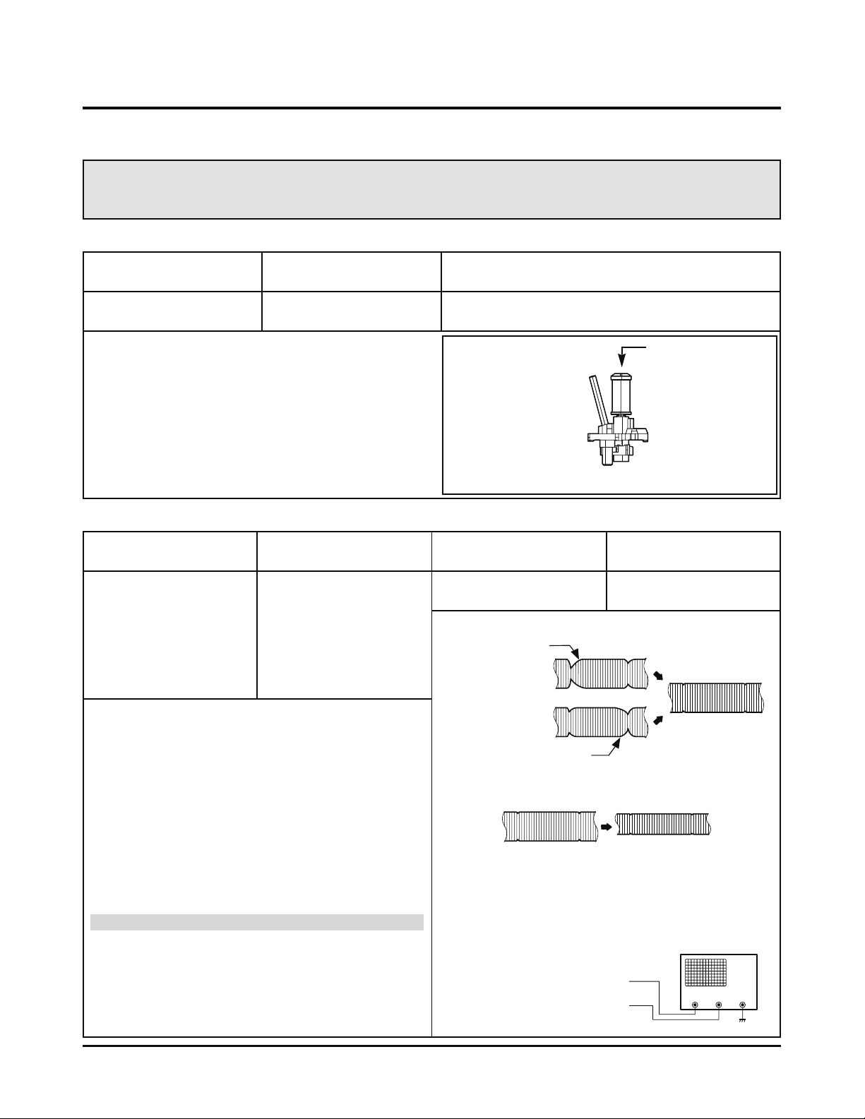
Purpose of adjustment : To ensure that the bottom surface of the tape can travel along with
the tape lead line of the lower drum by constantly and adjusting
and maintaining the height of the tape.
4. Guide Roller Height Adjustment
Fixtures and tools used VCR (VCP) status Adjustment position
• Post Height Adjusting
Driver
• Play or Review Mode
• The guide roller height adjusting screw on the
supply guide roller and the take-up guide roller
4-1. Prior Adjustment
1) Play the standard test tape after connecting the probe of
oscilloscope to the RF envelope output point and the
head switching output point.
2) Tracking control (playback) : Locate it at the center
(Set the RF output to the maximum value via the tracking control when such adjustment is completed after the
drum assembly is replaced.)
3) Height adjusting screw: Flatten the RF waveform.
(Fig. C-4-2)
4) Move the tracking control (playback) to the right/left.
(Fig. C-4-3)
5) Check the start and the end of the RF output reduction
width are constant.
CAUTIONS
There must exist no crumpling and folding of the tape due
to excess adjustment or insufficient adjustment.
Fig. C-4-2
Fig. C-4-2
P2 POST ADJUSTMENT
P3 POST ADJUSTMENT
CH-1 CH-2
RF ENVELOPE OUTPUT POINT
HEAD RF SWITCHING OUTPUT POINT
Flatten the waveform by
lightly turning the
guide roller height adjustment screw.
When turning the tracking
control to both sides.
OSCILLOSCOPE
When the tracking control
locates at the center.
Waveform
Connection Diagram
Fixtures and tools used
Measuring tools and
connection position
VCR (VCP) status Adjustment position
• Oscilloscope
• Standard test tape
• Post height adjusting
driver
• CH-1: PB RF Envelope
• CH-2: NTSC : SW 30Hz
PAL : SW 25Hz
• Head switching output
point
• RF Envelope output
point
• Play the standard test
tape.
• Guide roller height
adjusting screw
4-2. Fine Adjustment
Adjustment Procedure
1) Travel the tape and check the bottom surface of the
tape travels along with the guide line of the lower drum.
2) If the tape travels toward the lower part of guide line on
the lower drum, turn the guide roller height adjusting
screw to the left
3) If it travels to the upper part, turn it to the right.
4) Adjust the height of the guide roller to ensure that the
tape is guided on the guide line of the lower drum at the
inlet/outlet of the drum. (Fig. C-4-1)
4-15
Page 17
DECK MECHANISM ADJUSTMENT
8.3
Fig. C-5-1
A/C Head Base
Fig. C-5-2
Height Adjustment
Screw(B)
Tilt Adjustment
Screw(C)
Azimuth
Adjustment
Screw(A)
X-Value Adjustment
Hole
Fig. C-5-3
A/C Head
Tape
Tape
0.2~0.25mm
P4
A/C Head Assembly
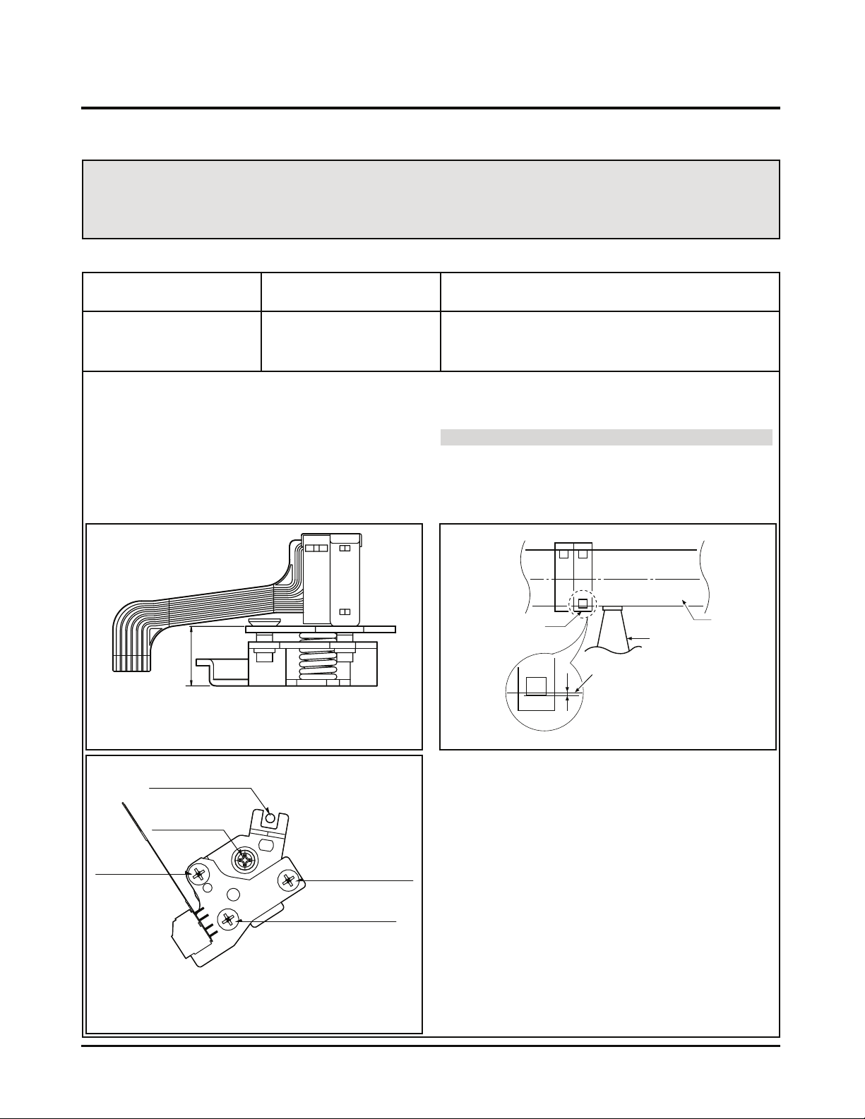
Purpose of adjustment : To ensure that audio and control signals can be recorded and
played according to the contract tract by constantly maintaining
distance between tape and head, and tape tension between the P3
post and the P4 post.
5. Audio/Control (A/C) Head Adjustment
Adjustment Procedure/Adjustment Diagrams
1) Basically use the A/C head assembly adjusted as in
SPEC.
2) Check there is crumpling and folding of the tape around
the A/C head. If it is, Turn and adjust the tilt adjusting
screw to ensure that the tape corresponds to the bottom
guide of the P4, and recheck the tape path after proceeding play for 4-5 seconds.
3) Where the tape bottom is not equal to Fig. C-5-3, Adjust
the height by using the height adjusting screw (B) and
then readjust it by using the tilt adjusting screw (C).
CAUTIONS
Always check the height of the A/C head since most ideal
height of A/C head can be obtained when the bottom part
of the tape is away 0.2 ~ 0.25mm from the bottom part of
the A/C head.
Fixtures and tools used VCR (VCP) status Adjustment position
• Blank Tape
(Empty Tape)
• Driver (+) Type ø 5
• Play the blank tape
(empty tape).
• Tilt adjusting screw (C)
• Height adjusting screw (B)
• Azimuth adjusting screw (A)
5-1. Prior Adjustment (performed only when no audio output appears in play of the standard test tape)
Fixed Screw
4-16
Page 18
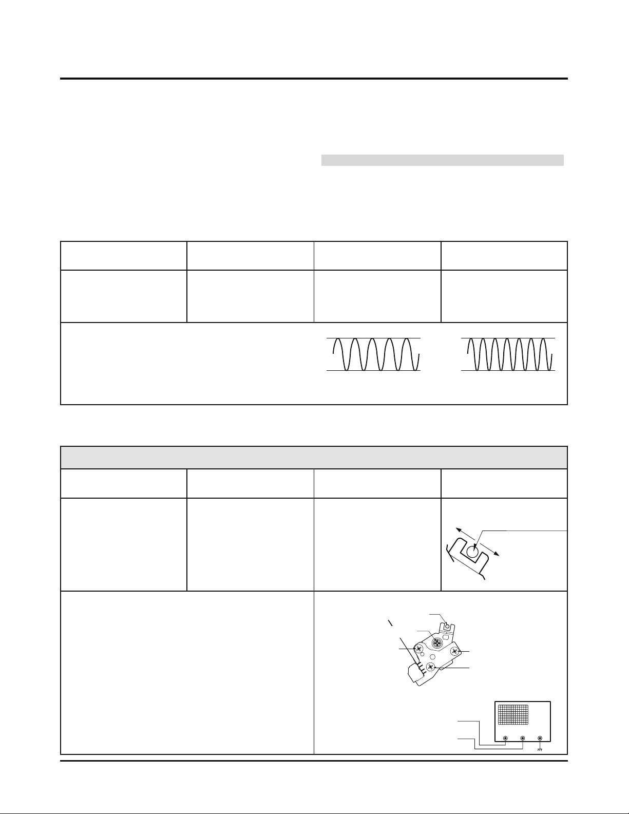
DECK MECHANISM ADJUSTMENT
1KHz
A: Maximum
7KHz
B: Minimum
Fig. C-6
Fixtures and tools used Connection position VCR (VCP) status Adjustment position
• Oscilloscope
• Standard test tape
(only for SP)
• Driver (+) Type Ø 4
• CH-1: PB RF Envelope
• CH-2: NTSC ; SW 30Hz
PAL:SW 25Hz
• Head switching output
point
• RF Envelope output
point
• Play the standard test
tape.
6. X-distance Adjustment
Left
X-distance Adjusting Hole
Tilt Adjusting Screw (C)
Fixing Screw
Height Adjusting
Screw (B)
Right
Grove of Base A/C
Purpose of adjustment : To maintain compatibility with other VCR (VCP).
RF ENVELOPE OUTPUT POINT
HEAD RF SWITCHING OUTPUT POINT
OSCILLOSCOPE
Connection Diagram
CH-2CH-1
Azimuth
Adjustment
Screw(A)
5-2. Tape Path Check between Pinch Roller and
Take up Guide (Check in the Rev Mode)
1) Check the tape pass status between the pinch roller and
the take-up guide.(Check there is crumpling of the tape
pass and folding of the take-up guide.)
1) (1) When holding of the take-up guide bottom occurs
Turn the tilt adjusting screw (C) clockwise and travel it
stably to ensure there is no crumbling or folding of the
tape.
1) (2) When holding of the take-up guide top occurs
Turn the tilt adjusting screw (C) anti-clockwise and
travel it stably to ensure there is no crumbling or folding of the tape.
1) 2) Check there is folding of the tape at the bottom or top
of the take-up guide in cutting-off the REV mode
CAUTIONS
If the RF waveform is changed after adjusting the A/C head,
perform fine adjustment to ensure the RF waveform is flattened.
5-3. Fine Adjustment (Azimuth Adjustment)
Fixtures and tools used Connection position VCR (VCP) status Adjustment position
• Oscilloscope
• Standard test tape
(only for SP)
• Driver (+) Type Ø 4
Adjustment Procedure
1) Connect the probe of Oscilloscope to the audio output
jack.
2) Ensure that Audio 1KHz, 7KHz output is flattened at the
maximization point by adjusting the Azimuth adjusting
screw (A).
• Audio Output Jack • Play the standard test
• Tape, 1KHz, 7KHz.
Fig. C-5-4
• Azimuth Adjusting
Screw (A)
• Height Adjusting Screw
(B)
Adjustment Procedure
1) After releasing the auto tracking, lightly turn the fixing
screw. Turn the (+) type driver (Ø 3 ~ Ø 4) on the X-distance adjusting hole to the right or left. Adjust the RF
envelope level to the maximum point and then fix the fixing screws.
2) For the 31mm head, adjust it with the SP tape recorded
in the width of 31mm since the head travels on the tape
track only for SP with the width of 58mm.
4-17
Page 19
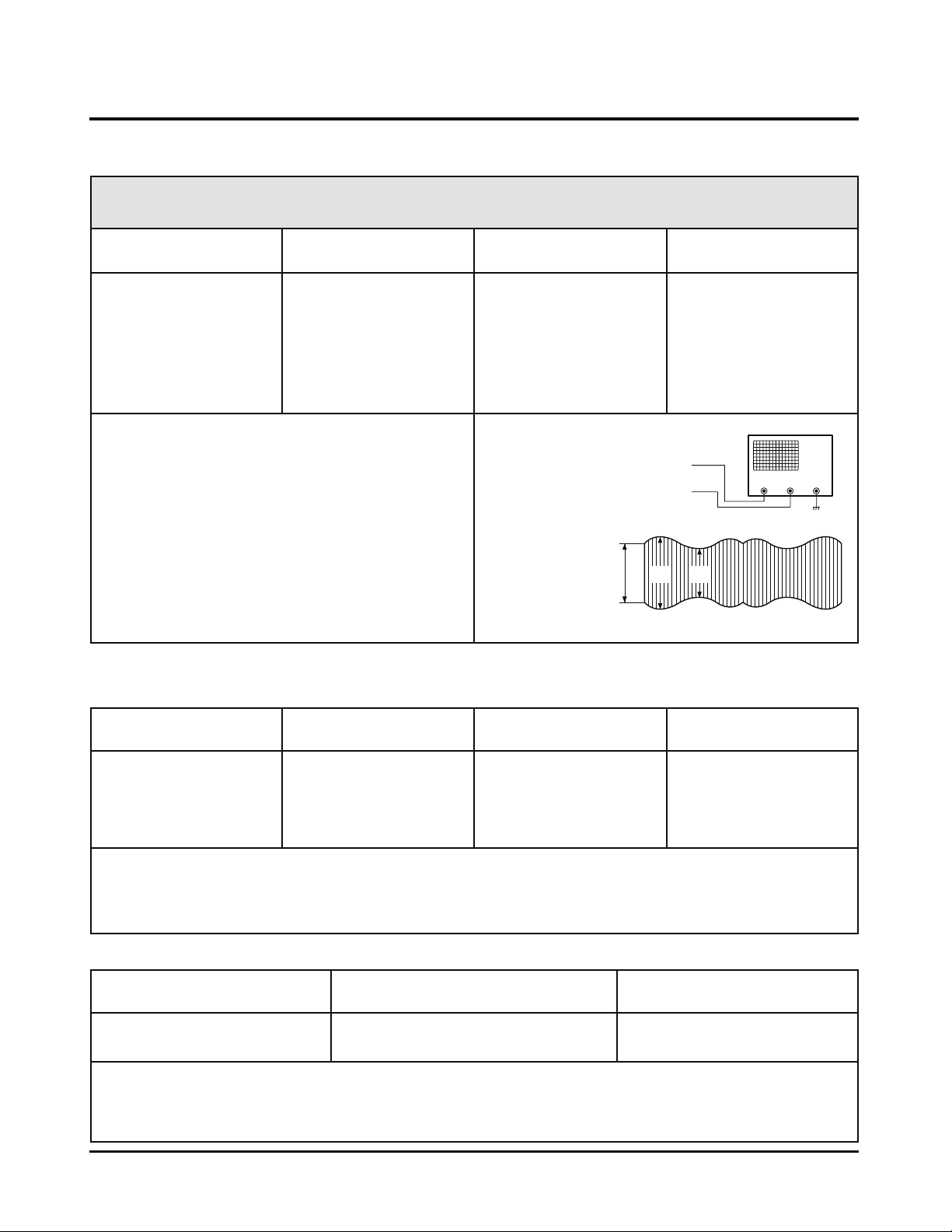
DECK MECHANISM ADJUSTMENT
RF ENVELOPE OUTPUT POINT
V2V1V1
V1/V MAX = 0.7
V1/V MAX = 0.8
RF ENVELOPE OUTPUT
HEAD RF SWITCHING OUTPUT POINT
OSCILLOSCOPE
Connection Diagram
Waveform
CH-2CH-1
Checking Procedure
1) Check that locking time of the RF and Audio waveform is
fallen within the measuring standard in conversion of the
play mode from the CUE or the REV mode.
2) Readjust the paragraph 5 and 6 if it deviates from the
standard.
Fixtures and tools used Measuring standard Connection position VCR (VCP) status
• Oscilloscope
• 6H 3KHz Color Bar
Standard Test tape
• Stop Watch
• RF Locking Time: Within
5 seconds
• Audio Locking Time :
Within 10 seconds
• CH-1: PB RF Envelope
• CH-2: Audio output
• RF Envelope output
point
• Audio output jack
• Play the 6H 3KHz
Color Bar Standard
Test tape.
8. Check of Traveling Device after Deck Assembly
8-1. Audio, RF Normalization Time (Locking Time) Check in Play after CUE or REV
Checking Procedure
1) Check there is no abnormality of every traveling post
status.
2) There must be no abnormal operation of the counter in
occurrence of folding of the bottom tape. There must be
not abnormality of audio signal in damage of the top tape.
3) If there is abnormality, readjust the adjustment paragraph 4 and 5.
Fixtures and tools used Fixtures and tools used Fixtures and tools used
• T-160 Tape
• T-120 Tape
• There must be no jam or curl at the
first, middle and end position of tape.
• Travel the tape at the position
of its first and end.
7. Adjustment after Drum Assembly (Video Heads)
Purpose of adjustment : To adjust and stabilize the height change, X-distance change, etc
depending on the guide roller after assembling the drum.
Fixtures and tools used Connection position VCR (VCP) status Adjustment position
• Oscilloscope
• Standard test tape
(only for SP)
• Post Height Adjusting
Driver
• Driver (+) Type Ø 5
• CH-1: PB RF Envelope
• CH-2: NTSC : SW 30Hz
PAL:SW 25Hz
• Head switching output
point
• RF Envelope output
point
Checking/Adjustment Procedure
1) Play the blank tape (empty tape) and check whether the
guide roller crumbles or wrinkles the tape and adjust it if
necessary.
2) Check that the RF envelope output waveform is flat, and
adjust the height of the guide roller while playing the
standard test tape.
3) Adjust the switching point.
4) Check the RF envelope output is the maximum when
the tracking control locates at the center. If not maximum, set up to ensure that RF envelope output
becomes the maximum by turning the (+) type driver (Ø
3 ~ Ø 4) on the base A/C groove.
• Play the blank tape.
• Play the standard test
tape.
• Fine adjustment of
guide roller
• Switching Point
• Tracking Preset
• X-distance
8-2. Check of Tape Curl and Jam Status
4-18
Page 20
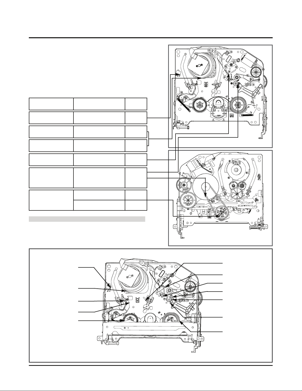
PROTECTION, MAINTENANCE AND CHECK OF VIDEO FUNCTION
4-19
(3) F/E Head
(5) Drum Assembly
(Video Head)
(4) Base Assembly P2
(2) Tension Post
(1) Supply Reel
(6) Base Assembly
P3
Phenomena
Replace-
ment
Checking Points and
Cause
Color beat Pollution of Full-Erase Head o
S/N, Color Faded Pollution of Video Head o
Horizontal, Vertical Jitte o
CAUTIONS
If operation of the position with (O) mark is abnormal even
after removing cause, replace it with substitute product since
it shows damage or wearing.
(7) A/C Head
(8) P4 Post
(10) Pinch Roller
(11) Take-up Guide
Post
(9) Capstan Shaft
(12) Take-up Reel
* No. (1) ~ (12) shows sequence that the tape moves from the supply reel to the take-up reel.)
Fig. C-9-1 TOP VIEW
Fig. C-9-2 BOTTOM VIEW
F/E Head
Video Head
A/C Head
Pinch Roller
Belt Capston
Clutch
Assembly A37
Fig. C-9-3 Tape Transport System
Pollution of Video Head or
Tape Transport System
Poor Sound, Low Sound o
Pollution of Audio/Control
Head
o
Pollution of Pinch Roller or
Belt Capstan Belt
No tape wound or tape
wound loosely.
FF or REW impossible,
or slow turning
Deterioration of Clutch
Assembly D37 Torque
Pollution of Drum and
Traveling Device
Tape loosely wound in
REV or Unloading
o
Fig. C-9-3
1. Checking Points prior to Repair
Following abnormal phenomena may be repaired by
removal of foreign materials and oil supply. Check oiling is
required at the checking set or cleaning status is complete.
Determine that necessity of checking and repair the set
exists after checking the using period of the set together
with the user. In this case, followings must be checked:
Page 21
PROTECTION, MAINTENANCE AND CHECK OF VIDEO FUNCTION
4-20
2. Essential Check and Repair
Recording density of the video is far higher than the audio.
Therefore video parts are very precise so as to allow only
error of 1/1000mm or so in order to maintain compatibility
with other videos.
If one of these parts is polluted or old, same phenomena will
appear as they are damaged.
To maintain clear screen, regular check, replacement of old
and damaged parts and oil supply, etc are essential.
3. Regular Check and Repair
Check and repair schedule is not constant since they vary
depending on method that the consumer uses video and
environment where the video is installed at.
However, for the video used by common household, good
screen will be maintained if regular check and repair per
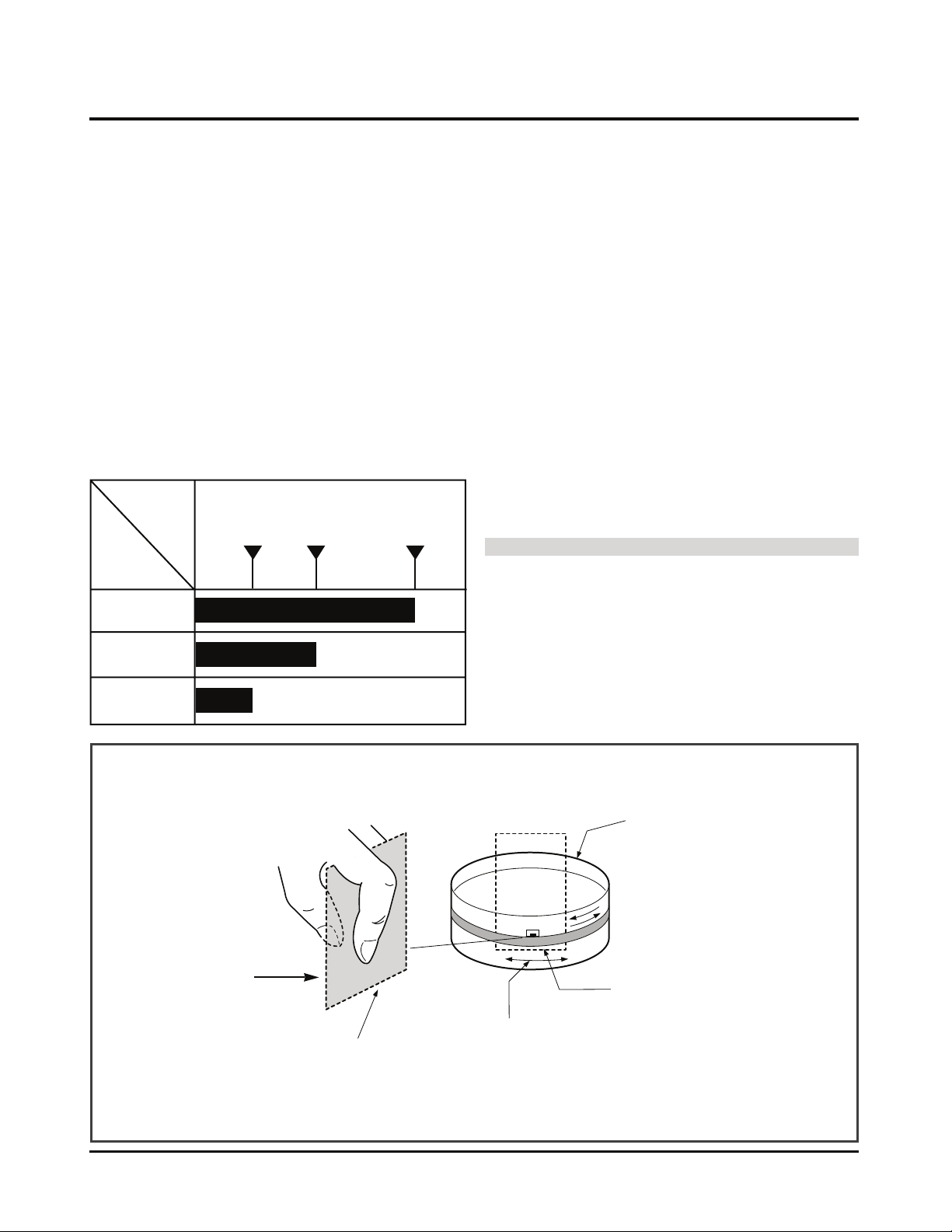
1,000 hour is performed. The following chart shows relationship between using time and checking time:
4. Tools for Check and Repair
(1) Grease: Floil G-3114 (KANTO) or equivalent grease
(Green)
(2) Grease: Kanto G-754, PL-433 (Yellow)
(3) Alcohol (Isopropyl Alcohol)
(4) Cleaning Patch (cloth)
5. Maintenance Process
5-1) Removal of Foreign Material
(1) Removal of foreign material from video head (Fig. C-9-4)
Firstly try to use a cleaning tape.
(1) Use a cleaning patch if foreign materials are not removed
with the cleaning tape due to severe dirty of the head.
Soak the cleaning patch in alcohol and put it to the head
tip. Smoothly turn the drum (turning cylinder) to the right
or left (In this case, the cleaning patch must not be
moved vertically).
(1) After completely drying the head, test the traveling status
of the tape.
(1) If alcohol (Isopropyl Alcohol) remains at the video head,
the tape may be damaged when this solution touches
with the head surface.
Never use a cloth bar (commercial sale)
(2) Wipe the tape transport system and the drive system
with the cleaning patch soaked in alcohol (Isopropyl
Alcohol) when removing foreign materials from them.
1) The part touched with the traveling tape is called as
tape transport system. The drive system consists of
parts to travel the tape.
(2) 2) Care must be exercised so that unreasonable force
to change the pattern will be applied to the tape transport system during removal of foreign materials.
About
1 year
One hour
Table 1
Two hours
Three hours
Time
Requiring
Checking
Average
hours used
per day
About
18 months
About
3 years
Fig. C-9-4
Drum
(Turning Cylinder)
Head Tip
Soak alcohol
(Isopropyl Alcohol).
Cleaning Patch
(Cloth)
Smoothly turn the drum (turning
cylinder) touching the soft surface
to the head tip surface.
Page 22
PROTECTION, MAINTENANCE AND CHECK OF VIDEO FUNCTION
5
4
2
1
3
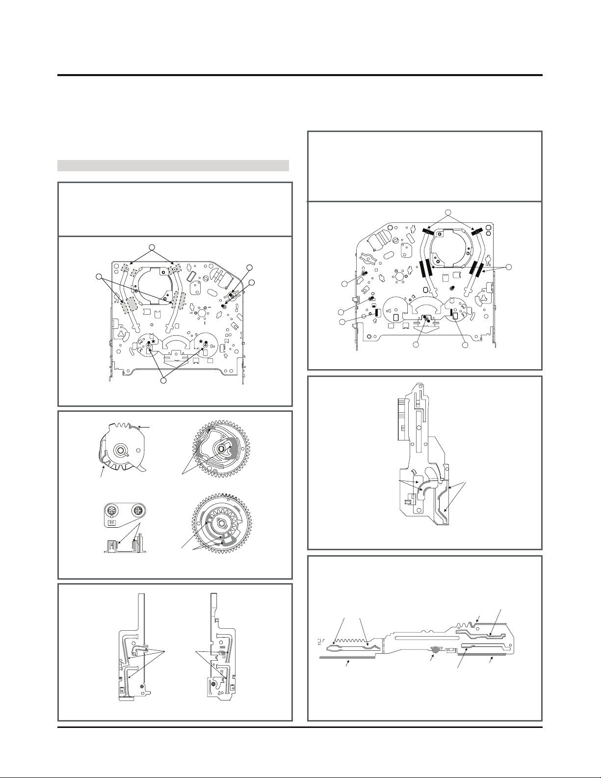
(1) Inner Side Surface and Top
Surface of Loading Path
(2) Stable Adhesion Part of Base
P2, P3
(3) Arm Pinch Shaft
(4) Gear Wheel Shaft
(5) Reel S. T. Shaft
(1) (2) (3) (4): KG-684G
(Green)
(5): PL-433 (Yellow)
Cam Part
(PL-433.Yellow)
Gear Part
(PL-433.Yellow)
Boss Part Side Wall
(PL-433.Yellow)
Gear Part Side Application
(PL-433.Yellow)
Cam Part Side Application
(KG-684G.Green)
Gear Sector Gear Cam
Base Loading Gear Drive
Inner Surface of
Guide Rail
(KG-684G.Green)
Chassis (L) Chassis (R)
Gear Part
1
2
3
4
6
5
7
(1) Inner Side Surface and Top
Surface of Loading Path
(2) Stable Adhesion Part of Base
P2, P3 Coil
(3) Gear Cam Shaft
(4) Gear Drive Shaft
(5) Clutch Shaft Groove
(6) Guide Part on the Plate Slider
Side Wall (Left)
(7) Guide Part on the Plate Slider
Side Wall (Right)
(1) (2) (3) (4) (5) (6) (7): KG684G (Green)
Chassis (TOP)
Chassis (Bottom)
Cam Part
(KG-684G , GREEN)
Cam Part
(KG-684G , GREEN)
Gear Rack F/L
Lever, Brake Driving Cam Part
Side Wall Guide Part
Lever F/R Driving Part
Side Wall Guide Part
Lever, Spring Driving Part
Lever Tension Driving Cam Part
Gear Sector Driving Part
Plate Slider
5-2) Grease Applications
(1) Grease Application Method
Apply grease by using a cloth swab or brush. Care must
be exercised so that excess quantity should not be
used. If the excessive quantity is applied, wipe it with
the gauze soaked in alcohol (Isopropyl Alcohol).
NOTE: POSITION OF GREASE APPLICATION
(2) Regular Grease Application
Apply grease to the designated application position
every 500 hour.
4-21
Page 23
PROTECTION, MAINTENANCE AND CHECK OF VIDEO FUNCTION
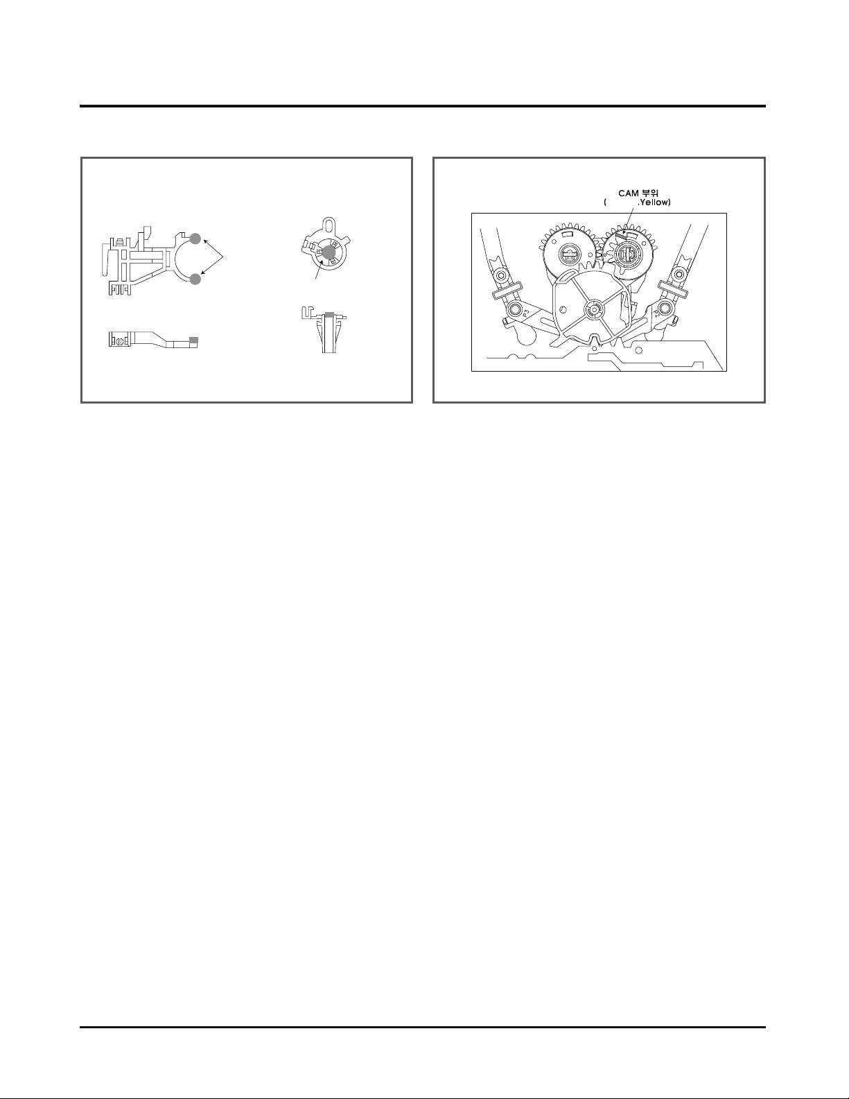
LEVER, F/R
Clutch Contact Part
(PL-433, Yellow)
Tension Arm Party
Hinge Part (PL-433, Yellow)
BASE, TENSION
PL-433
Lever, F/R, Base, Tension GEAR AY, P2 & P3
4-22
Page 24
MECHANISM TROUBLESHOOTING GUIDE
4-23
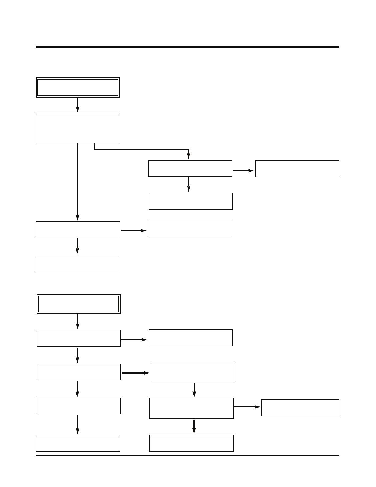
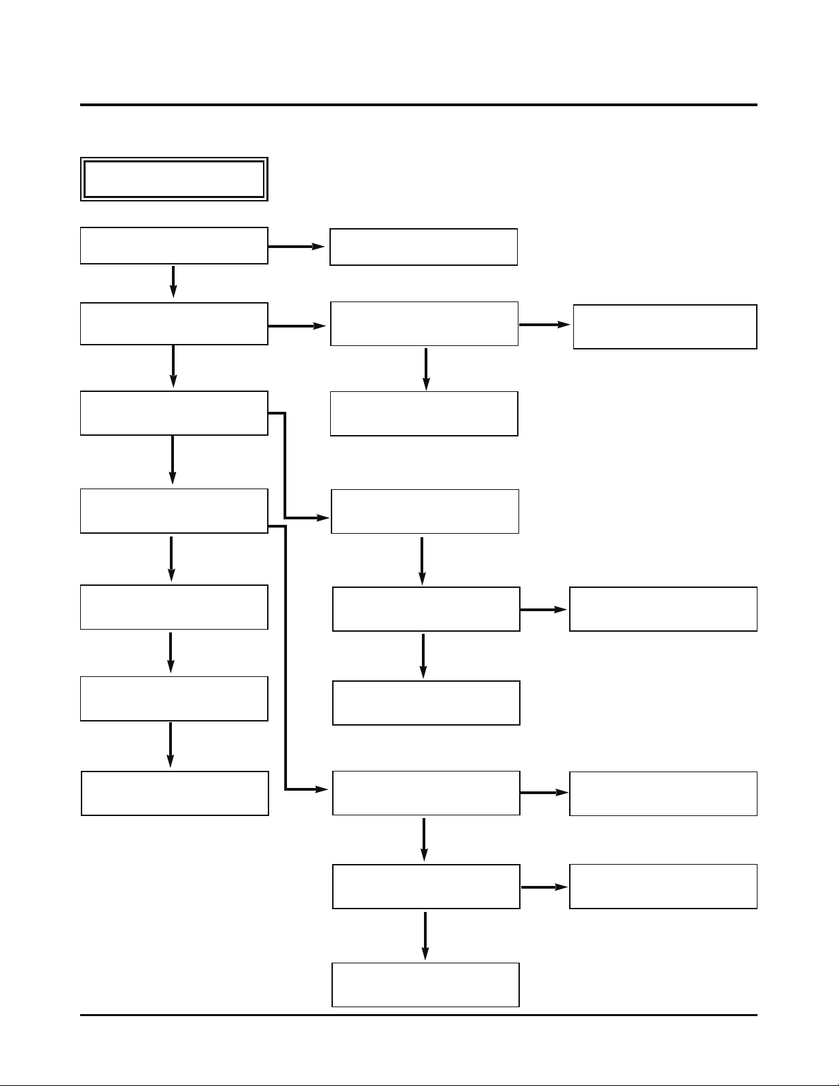
No Auto Rewind operates.
Is output of the end sensor “H”?
“H”: 3.5V or less
“L”: 0.7V –1V or less
Is voltage at both ends of the
IR LED 0.8V-1.5?
Replace the LED.
Is the end sensor Vcc applied at
5V?
Check the Syscon power supply.
Replace the end sensor.
Is the Syscon checked?
NO
YES
YES
YES
YES
NO
NO
1.Deck Mechanism
A.
NO
NO
NO
No F/R operates.
Is the current mode an F/R
mode?
Check the assembly position of
the Mode S/W.
Is normal voltage applied at the
Vcc1 and the Vcc2 of the
Capstan motor?
Is the Vctl terminal voltage of the
Capstan Motor applied at more
than 4V?
Check the Servo, Power
circuit.
Replace the Capstan motor.
Does the Capstan motor rotate?
Does the T/up and the supply
reel Operate?
Check the Syscon circuit.
YES
YES
YES
YES
YES
YES
B.
Page 25
MECHANISM TROUBLESHOOTING GUIDE
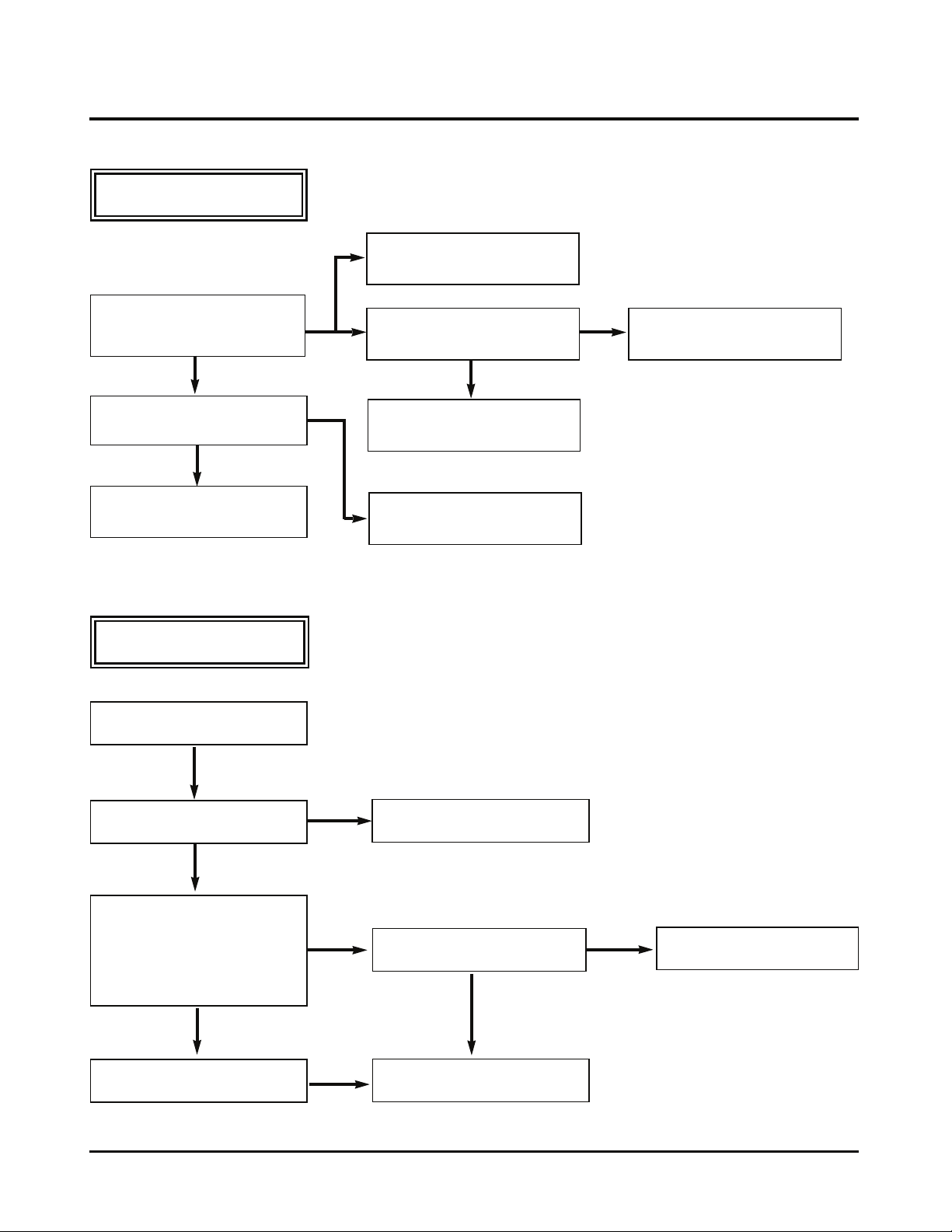
C.
Auto Stop operates.
(PLAY/CUE/REV)
Check the assembly mode.
Check the spring pinch.
Does the pinch roller attached to
the Capstan shaft turn in operation of the Play/Cue/Rev.
YES
Does the T/UP or the supply
reel pulse occur?
YES
Check the Syscon, µ-com.
D.
No cassette loading is done.
Insert the cassette.
NO
NO
Is output of the DFG, DPG
normal?
YES
Check the Servo, Syscon.
Replace the reel sensor.
NO
Replace the drum motor.
YES
Is operation of the lever
assembly S/W normal?
YES
Does output of the CST IN S/W
change?
(In insertion of the REC tape:
“L”_“H”_ “L”)
(In insertion of the REC prevention tape:
“L”_ “H”_ “L”_ “H”)
YES
Check the Syscon circuit.
NO
NO
NO
Check the holder assembly CST.
Is the CST IN S/W normal?
YES
Check the Syscon circuit.
NO
Replace the CST IN S/W.
4-24
Page 26
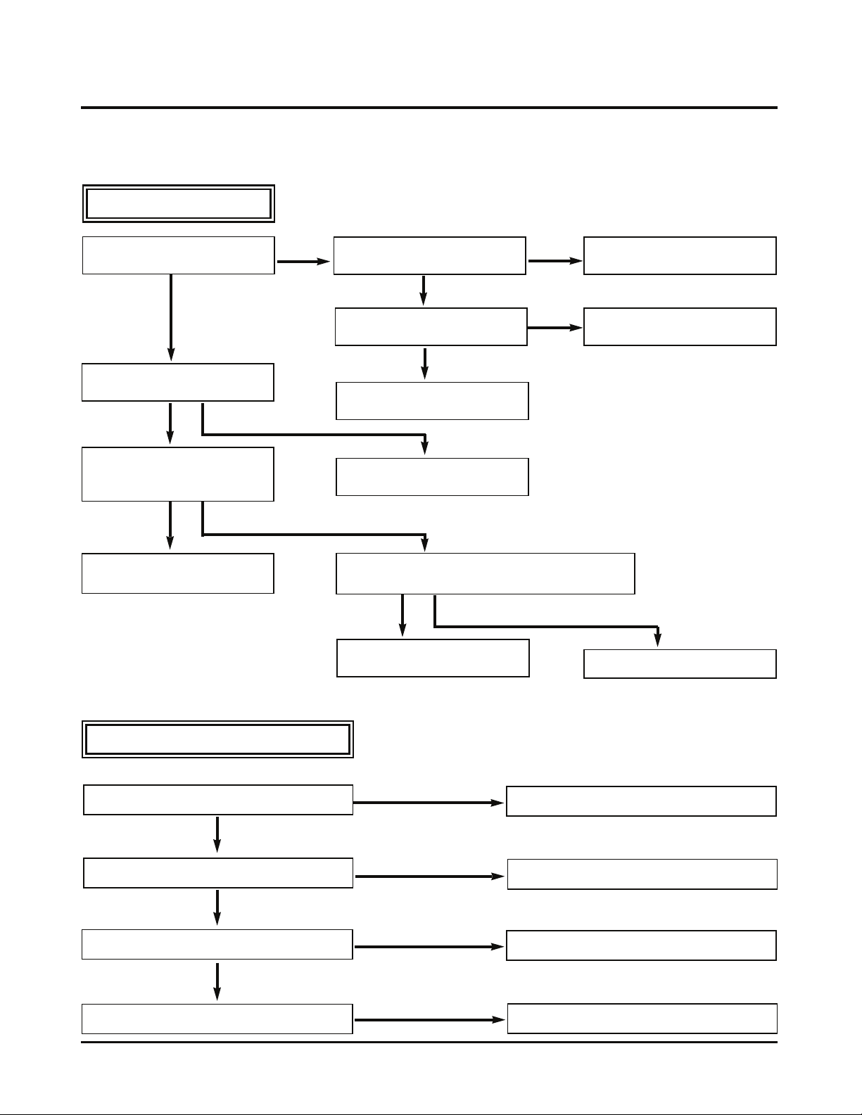
MECHANISM TROUBLESHOOTING GUIDE
E.
No tape winding is done in
play.
Is the pinch roller attached to the
Capstan shaft in operation of play?
YES
Does the T/up reel operate?
YES
Does the Capstan motor turn?
YES
Does the drum motor turn?
YES
Is the DPG, DFG normal?
NO
NO
NO
Check the assembly mode?
Is the Capstan belt hung?
YES
Check the clutch and the idler
assembly.
Is normal voltage applied to the
capstan motor Vcc1, Vcc2?
YES
Is the Vctl terminal voltage of
the Capstan motor applied at
more than 4V?
NO
Hang the Capstan belt.
NO
Check the Servo, power circuit.
YES
Are the T/up and the reel sensor
normal?
YES
Check the Syscon circuit.
4-25
NO
YES
Replace the Capstan motor.
Is the Vcc voltage of the drum
motor normal?
YES
Is the Vctl terminal voltage of the
drum motor at more than 2.3V?
YES
Replace the drum motor.
NO
Check the Syscon circuit.
NO
Check the Syscon circuit.
Page 27
MECHANISM TROUBLESHOOTING GUIDE
2. Front Loading Mechanism
A.
No cassette insert is done.
Does the lever assembly
switch operate?
YES
Is the Vcc of the main P.C.B
assembly?
YES
Is voltage between the cassette
switch terminal and the GND on
the main P.C.B assembly?
YES
Check the mode switch position
and the Syscon circuit.
NO
NO
NO
Is the lever assembly switch
spring normal?
NO
Add or replace the lever
assembly switches spring.
YES
Does the CST IN switch
operate normally?
NO
Replace the F/L switch.
YES
Check the Syscon circuit.
Check the power circuit.
Is there short between the cassette switch terminal
and the GND on the main P.C.B assembly?
YES
Replace the main P.C.B assembly or remove the short part.
NO
Replace the CST IN switch.
B.
No cassette eject is done.
Does the L/D motor turn in reverse?
YES
Does the lever assembly switch operate?
YES
Does the arm assembly F/G operate?
YES
Does the opener door operate?
NO
Check the L/D motor and the drive IC.
NO
Replace the lever assembly switch.
NO
Replace the arm assembly F/L
NO
Replace the opener door.
4-26
Page 28
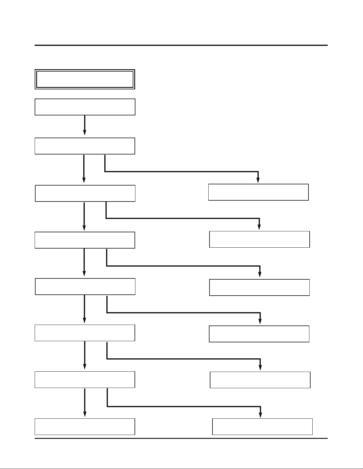
MECHANISM TROUBLESHOOTING GUIDE
C.
No safe adherence of tape is done.
Is cassette insert done?
YES
Does the opener lid operate?
YES
Does the gear rack F/L operate?
NO
NO
YES
Does the opener door operate?
YES
Does the arm assembly F/L operate?
YES
Does the L/D motor operate?
NO
NO
Replace the opener lid.
Replace the gear rack F/L.
Check the assembly status of the
opener door.
Replace the arm assembly F/L.
YES
Does the holder assembly cassette move
same as the arm assembly F/L?
YES
Replace the front loading mechanism
assembly.
4-27
NO
NO
Check power supply of the L/D motor.
Check the assembly status of the
holder assembly cassette.
 Loading...