

Philips DVP-3358-K, DVP-3358 Service Manual
DVP3358(K)
DVP3358K/93
DVP3358/96
Service Manual
TABLE OF CONTENTS
. Technical Specifications…………....………………………..............1-2
. Safety Instruction, Warning & Notes….……………………....….....1-3
. DFU Instruction..............................................................................2-1
. Mechanical and Dismantling Instructions…………........................3-1
. Software Version & Upgrades, Region Code Change..…….........
. Trouble Shooting Chart………………………………………………
. Wiring Diagram………………………………………..………..….….6-1
. Electrical Diagrams and Print-layouts..….…………………....….…7-1
. Set Mechanical Exploded view & Part list.…………………..….….8-1
. Revision List..................................................................................9-1
©Copyright 2009 Philips Consumer Electronics B.V. Eindhoven, The Netherlands
All rights reserved. No part of this publication may be reproduced, stored in aretrieval system or
transmitted, in any form or by any means, electronic, mechanical, photocopying, or otherwise
without the prior permission of Philips.
Page
.
4-1
.
5-1
CLASS 1
LASER PRODUCT
Published by FK-091
Version 1.1
5 BU AVM Printed in The Netherlands Subject to modification
GB
3142 785 33631
PHILIPS

6SHFLÀFDWLRQ
for DVP3358K/93
Note
6SHFLÀFDWLRQDQGGHVLJQDUHVXEMHFWWRFKDQJH
without notice.
Accessories supplied
Remote control and batteries
Audio/video cables
AC Power cable
User Manual
Playback media
DVD-Video, Video CD/SVCD, Audio CD, CD-R/
CD-RW, DVD+R/+RW, DVD-R/-RW, DivX-CD,
3LFWXUH&'03&':0$&'86%ÁDVKGULYH
1-2
Frequency response:
DVD: 4 Hz - 22 kHz (48 kHz);
4 Hz - 44 kHz (96 kHz)
SVCD: 4 Hz - 20 kHz (44.1 kHz);
4 Hz - 22 kHz (48 kHz)
CD/VCD: 4 Hz - 20 kHz (44.1 kHz)
Signal-Noise (1 kHz): > 90 dB
Dynamic range (1 kHz): > 80 dB
Crosstalk (1 kHz): > 70 dB
Distortion/noise (1 kHz): > 65 dB
MPEG MP3: MPEG Audio L3
Audio format
Digital:
MPEG/AC-3/PCM: Compressed digital (16, 20, 24
bits fs, 44.1, 48, 96 kHz)
MP3 (ISO 9660): 96, 112, 128, 256 kbps &
variable bit rate fs, 32, 44.1, 48 kHz
Analog sound stereo
Dolby surround compatible downmix from Dolby
Digital multi-channel sound
USB
Compatibility: Hi-Speed USB (2.0)
Class support: UMS (USB Mass Storage Class)
TV standard
Number of lines:
625 (PAL/50Hz); 525 (NTSC/60Hz)
Playback: Multi-standard (PAL/NTSC)
Video performance
Video DAC: 12 bits, 108 MHz
Y Pb Pr: 0.7 Vpp ~ 75 ohm
Video output: 1 Vpp ~ 75 ohm
Video format
Digital compression:
MPEG 2: DVD/SVCD
MPEG 1: VCD/DivX
Horizontal resolution:
DVD: 720 pixels (50 Hz); 720 pixels (60 Hz)
VCD: 352 pixels (50 Hz); 352 pixels (60 Hz)
Vertical resolution:
DVD: 576 lines (50 Hz); 480 lines (60 Hz)
VCD: 288 lines (50 Hz); 240 lines (60 Hz)
Connections
Y Pb Pr output: Cinch 3x
Video output: Cinch (yellow)
Audio output (L+R): Cinch (white/red)
Digital output:
1 coaxial: IEC60958 for CDDA/LPCM;
IEC61937 for MPEG 1/2, Dolby Digital
Main unit
Dimensions (w x h x d): 360 x 38 x 203 (mm)
Net Weight: approximately 1.3 kg
Power
Power supply rating: 110 V - 240V; 50/60 Hz
Power consumption: < 10 W
Power consumption in standby mode: < 1 W
/DVHU6SHFLÀFDWLRQ
Type: Semiconductor laser InGaAIP (DVD), AIGaAs
(CD)
Wave length: 658 nm (DVD), 790 nm (CD)
Output Power: 7.0 mW (DVD), 10.0 mW (VCD/CD)
Beam divergence: 60 degrees
Audio performance
DA converter: 24 bits, 192 kHz

Specifi cation
for DVP3358/96
Note
Specifi cation and design are subject to change
•
without notice.
Accessories supplied
Remote control and batteries•
Audio/video cables•
Playback media
DVD-Video, Video CD/SVCD, Audio CD, CD-R/•
CD-RW, DVD+R/+RW, DVD-R/-RW, DivX-CD,
Picture CD, MP3-CD, WMA-CD, USB fl ash drive
USB
Compatibility: Hi-Speed USB (2.0)•
Class support: UMS (USB Mass Storage Class) •
TV standard
Number of lines:•
625 (PAL/50Hz); 525 (NTSC/60Hz)•
Playback: Multi-standard (PAL/NTSC)•
Video performance
Video DAC: 12 bits, 108 MHz•
Y Pb Pr: 0.7 Vpp ~ 75 ohm•
Video output: 1 Vpp ~ 75 ohm•
Video format
Digital compression: •
MPEG 2: DVD/SVCD •
MPEG 1: VCD/DivX•
Horizontal resolution: •
DVD: 720 pixels (50 Hz); 720 pixels (60 Hz) •
VCD: 352 pixels (50 Hz); 352 pixels (60 Hz) •
Vertical resolution: •
DVD: 576 lines (50 Hz); 480 lines (60 Hz) •
VCD: 288 lines (50 Hz); 240 lines (60 Hz) •
1-2
Frequency response: •
DVD: 4 Hz - 22 kHz (48 kHz); •
4 Hz - 44 kHz (96 kHz)
SVCD: 4 Hz - 20 kHz (44.1 kHz); •
4 Hz - 22 kHz (48 kHz)
CD/VCD: 4 Hz - 20 kHz (44.1 kHz)•
Signal-Noise (1 kHz): > 90 dB (A-weighted)•
Dynamic range (1 kHz): > 80 dB (A-weighted)•
Crosstalk (1 kHz): > 70 dB•
Distortion/noise (1 kHz): > 65 dB•
MPEG MP3: MPEG Audio L3•
Audio format
Digital:•
MPEG/AC-3/PCM: Compressed digital (16, 20, 24 •
bits fs, 44.1, 48, 96 kHz)
MP3 (ISO 9660): 96, 112, 128, 256 kbps &•
variable bit rate fs, 32, 44.1, 48 kHz
Analog sound stereo•
Dolby surround compatible downmix from Dolby •
Digital multi-channel sound
Connections
Y Pb Pr output: Cinch 3x•
Video output: Cinch (yellow)•
Audio output (L+R): Cinch (white/red)•
Digital output: •
1 coaxial: IEC60958 for CDDA/LPCM;•
IEC61937 for MPEG 1/2, Dolby Digital
5.1 channel analog output•
Audio Front L + R: Cinch (white/red)•
Audio Rear L + R: Cinch (white/red)•
Audio Center: Cinch (blue)•
Audio Subwoofer: Cinch (black)•
Main unit
Dimensions (w x h x d): 360 x 37 x 209 (mm)•
Net Weight: approximately 1.3 kg•
Power
Power supply rating: 110 V - 240V; 50/60 Hz•
Power consumption: < 10 W•
Power consumption in standby mode: < 1 W•
Audio performance
DA converter: 24 bits, 192 kHz•
Laser Specifi cation
Type: Semiconductor laser InGaAIP (DVD), AIGaAs •
(CD)
Wave length: 658 nm (DVD), 790 nm (CD)•
Output Power: 7.0 mW (DVD), 10.0 mW (VCD/CD)•
Beam divergence: 60 degrees•

1-3
Safety instruction, Warning & Notes
Safety instruction
1. General safety
Safety regulations require that during a repair:
. Connect the unit to the mains via an isolation transformer.
. Replace safety components indicated by the symbol
only by components identical to the original ones. Any
other component substitution (other than original type)
may increase risk of fire or electrical shock hazard.
Safety regulations require that after a repair, you must
return the unit in its original condition. Pay, in particular,
attention to the following points:
. Route the wires/cables correctly, and fix them with the
mounted cable clamps.
. Check the insulation of the mains lead for external
damage.
. Check the electrical DC resistance between the mains
plug and the secondary side:
1) Unplug the mains cord, and connect a wire between
the two pins of the mains plug.
2) Set the mains switch the “on” position (keep the
mains cord unplug).
3) Measure the resistance value between the mains
plug and the front panel, controls, and chassis
bottom.
4) Repair or correct unit when the resistance
measurement is less than 1M
5) Verify this, before you return the unit to the
customer/user (ref. UL-standard no. 1492).
6) Switch the unit “off”, and remove the wire between
the two pins of the mains plug.
¡
.
2.Laser safety
This unit employs a laser. Only qualified service personnel
,
may remove the cover, or attempt to service this device
(due to possible eye injury).
Laser device unit
Type : Semiconductor laser GaAlAs
Wavelength : 650nm (DVD)
: 780nm (VCD/CD)
Output power : 7mW (DVD)
: 10mW (DVD /CD)
Beam divergence: 60 degree
Note: Use of controls or adjustments or performance of
procedure other than those specified herein, may result in
hazardous radiation exposure. Avoid direct exposure to
beam.

Warning
1-4
1.General
. All ICs and many other semiconductors are susceptible to
electrostatic discharges (ESD). Careless handing during
repair can reduce life drastically. Make sure that, during
repair, you are at the same potential as the mass of the
set by a wristband with resistance. Keep components and
tools at this same potential. Available ESD protection
equipment:
1) Complete kit ESD3 (small tablemat, wristband,
connection box, extension cable and earth cable)
4822 310 10671.
2) Wristband tester 4822 344 13999.
. Be careful during measurements in the live voltage
section. The primary side of the power supply , including
the heat sink, carries live mains voltage when you
connect the player to the mains (even when the player is
“off”!). It is possible to touch copper tracks and/or
components in this unshielded primary area, when you
service the player. Service personnel must take
precautions to prevent touching this area or components
in this area. A “lighting stroke” and a stripe-marked
printing on the printed wiring board, indicate the primary
side of the power supply.
. Never replace modules, or components, while the unit is
“on”.
2. Laser
. The use of optical instruments with this product, will
increase eye hazard.
. Only qualified service personnel may remove the cover
or attempt to service this device, due to possible eye
injury.
. Repair handing should take place as much as possible
with a disc loaded inside the player.
. Text below is placed inside the unit, on the laser cover
shield:
CAUTION: VISIBLE AND INVISIBLE LASER
RADIATION WHEN OPEN, AVOID EXPOSURE
TO BEAM.
Notes: Manufactured under licence from Dolby
Laboratories. The double-D symbol is trademarks of Dolby
Laboratories, Inc. All rights reserved.

Notes
Lead-Free requirement for service
1-5
INDENTIFICATION:
Regardless of special logo (not always indicated)
One must treat all sets from 1.1.2005 onwards, according
next rules.
Important note
be treated in this way as long as you avoid mixing
solder-alloys (leaded/ lead-free). So best to always use
SAC305 and the higher temperatures belong to this.
Due to lead-free technology some rules have to be
respected by the workshop during a repair:
x Use only lead-free solder alloy Philips SAC305 with
order code 0622 149 00106. If lead-free solder-paste is
required, please contact the manufacturer of your
solder-equipment. In general use of solder-paste within
workshops should be avoided because paste is not easy
to store and to handle.
x Use only adequate solder tools applicable for lead-free
solder alloy. The solder tool must be able
o To reach at least a solder-temperature of 400°C,
o To stabilize the adjusted temperature at the
o To exchange solder-tips for different applications.
x Adjust your solder tool so that a temperature around
360°C
joint. Heating-time of the solder-joint should not exceed
~ 4 sec. Avoid temperatures above 400°C otherwise
wear-out of tips will rise drastically and flux-fluid will be
destroyed. To avoid wear-out of tips switch off un-used
equipment, or reduce heat.
x Mix of lead-free solder alloy / parts with leaded solder
alloy / parts is possible but PHILIPS recommends
strongly to avoid mixed
solder alloy types (leaded and lead-free). If one cannot
avoid, clean carefully the
solder-joint from old solder alloy and re-solder with new
solder alloy (SAC305).
: In fact also products a little older can also
solder-tip
– 380°C is reached and stabilized at the solder
x Use only original spare-parts listed in the
Service-Manuals. Not listed standard-material
(commodities) has to be purchased at external
companies.
x Special information for BGA-ICs:
- always use the 12nc-recognizable soldering
temperature profile of the specific BGA (for
de-soldering always use highest lead-free
temperature profile, in case of doubt)
- lead free BGA-ICs will be delivered in so-called
‘dry-packaging’ (sealed pack including a silica gel
pack) to protect the IC against moisture. After
opening, dependent of MSL-level seen on
indicator-label in the bag, the BGA-IC possibly
still has to be baked dry. This will be
communicated via AYS-website.
Do not re-use BGAs at all.
x For sets produced before 1.1.2005, containing
leaded soldering-tin and components, all needed
spare-parts will be available till the end of the
service-period. For repair of such sets nothing
changes.
x On our website:
www.atyourservice.ce.Philips.com
You find more information to:
BGA-de-/soldering (+ baking instructions)
Heating-profiles of BGAs and other ICs used in
Philips-sets
You will find this and more technical information
within the “magazine”, chapter “workshop news”.
For additional questions please contact your local
repair-helpdesk.
DVP3358K/93
2-1
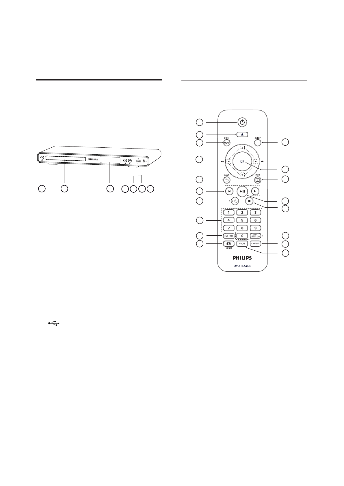
Product overview
Main unit
a
2
(Standby-on)
Turn on the DVD player or switch to •
standby mode.
Disc compartment
b
Remote control
1
2
3
4
5
31 2
4
7
6
5
6
7
8
9
10
18
17
16
15
14
13
12
11
Display panel
c
Z (Open/Close)
d
Open or close the disc compartment.•
u (Play/Pause)
e
Start, pause or resume disc play.•
f
(USB) jack
Connect a USB fl ash drive.•
g
MIC
Audio input from a microphone.•
2
a
(Standby-On)
Turn on the DVD player or switch to •
standby mode.
b
Z (Open/Close)
Open or close the disc compartment.•
c
DISC MENU
Access or exit the disc menu.•
Switch to disc mode.•
For VCD/SVCD, turn PBC (Playback •
Control) on or off in PBC mode.

DVP3358K/93
d
v V b B (Navigation buttons)
Navigate through the menus.•
Search fast-forward (• B) or fast-
backward (b). Press repeatedly to
change the search speed.
Search slow-forward (• v) or slowbackward (V). Press repeatedly to
change the search speed.
2 BACK
e
Return to the previous display menu.•
For DVD, navigate to the title menu.•
For VCD version 2.0 or SVCD with •
PBC turned on, return to the menu.
f
í/ë (Previous/Next)
Skip to the previous or next title, •
chapter, or track.
Press and hold for fast-backward or •
fast-forward search.
2-2
AUDIO/CREATE MP3
m
Select an audio language/channel.•
Access the menu to create MP3.•
n
x (Stop)
Stop disc play.•
o
u (Play/Pause)
Start, pause or resume disc play.•
p
q
r
INFO
For disc, display the current status or •
disc information.
For slideshows, display a thumbnail view •
of photo fi les.
OK
Confi rm an entry or selection.•
SETUP
Access or exit the setup menu.•
g
h
i
j ,
k
l
(USB)
Switch to USB mode and display the •
content.
Numeric buttons
Select an item to play.•
SUBTITLE
Select DVD or DivX subtitle language.•
Access the menu to USB copy or USB •
delete.
ZOOM
Fit the picture format to the TV screen.•
Zoom in or out of the picture.•
VOCAL
Change the audio channel of a karaoke •
disc.
KARAOKE
Access or exit the karaoke menu.•
DVP3358/96
2-1
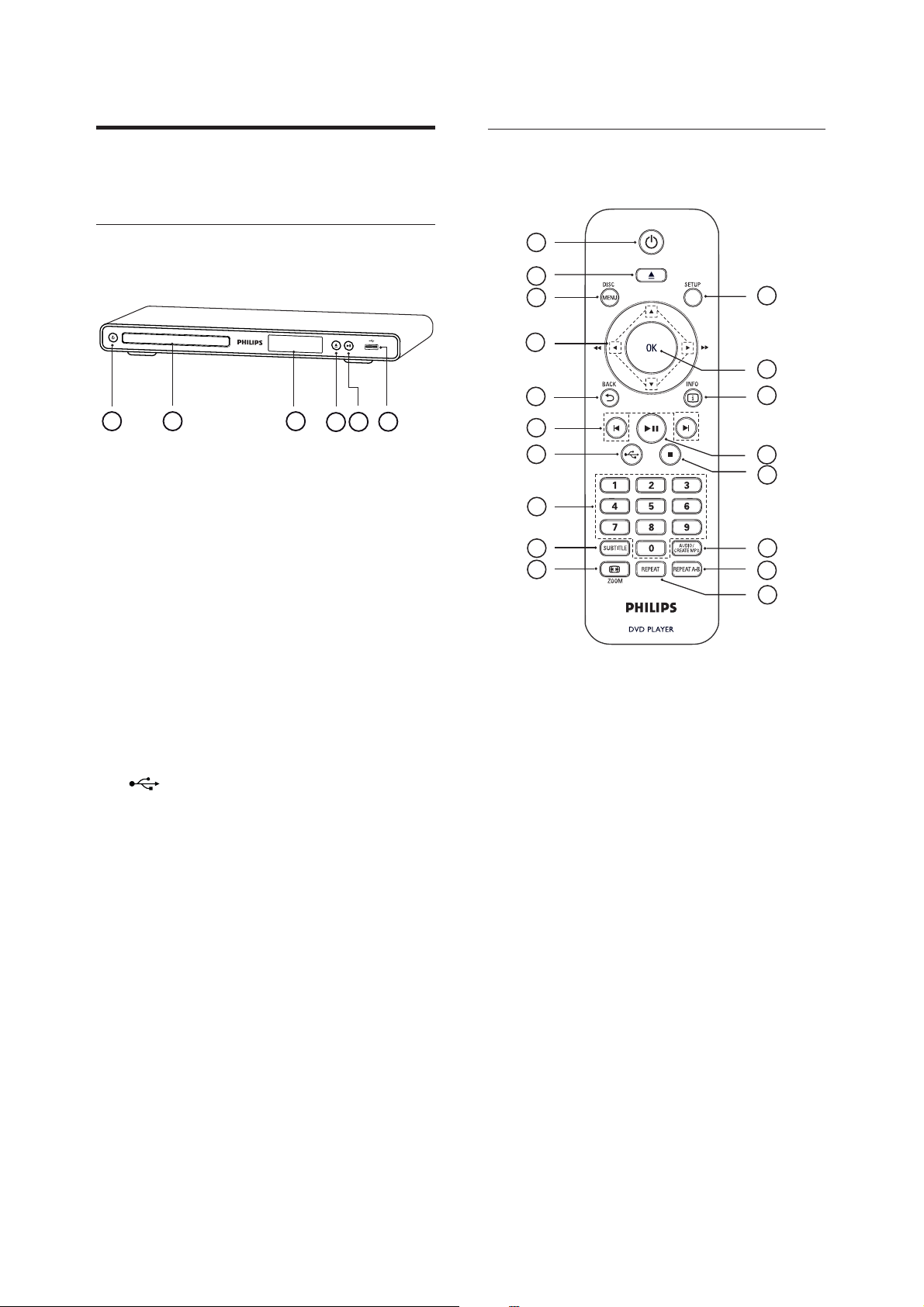
Product overview
Main unit
a
b
(Standby-on)
2
Turn on the DVD player or switch to •
standby mode.
Disc compartment
Remote control
1
2
3
4
5
31 2
4
6
5
6
7
8
9
10
18
17
16
15
14
13
12
11
Display panel
c
d
Z (Open/Close)
Open or close the disc compartment.•
u (Play/Pause)
e
Start, pause or resume disc play.•
f
(USB) jack
Connect a USB fl ash drive.•
a
2
(Standby-On)
Turn on the DVD player or switch to •
standby mode.
Z (Open/Close)
b
Open or close the disc compartment.•
c
DISC MENU
Access or exit the disc menu.•
Switch to disc mode.•
For VCD/SVCD, turn PBC (Playback •
Control) on or off in PBC mode.

DVP3358/96
v V b B (Navigation buttons)
d
2-2
AUDIO/CREATE MP3
m
Navigate through the menus.•
Search fast-forward (• B) or fast-
backward (b). Press repeatedly to
change the search speed.
Search slow-forward (• v) or slowbackward (V). Press repeatedly to
change the search speed.
e
2 BACK
Return to the previous display menu.•
For DVD, navigate to the title menu.•
For VCD version 2.0 or SVCD with •
PBC turned on, return to the menu.
í/ë (Previous/Next)
f
Skip to the previous or next title, •
chapter, or track.
Press and hold for fast-backward or •
fast-forward search.
Select an audio language/channel.•
Access the menu to create MP3.•
n
x (Stop)
Stop disc play.•
o
u (Play/Pause)
Start, pause or resume disc play.•
p
q
r
INFO
For disc, display the current status or •
disc information.
For slideshows, display a thumbnail view •
of photo fi les.
OK
Confi rm an entry or selection.•
SETUP
Access or exit the setup menu.•
g
h
i
j ,
k
l
(USB)
Switch to USB mode and display the •
content.
Numeric buttons
Select an item to play.•
SUBTITLE
Select DVD or DivX subtitle language.•
Access the menu to USB copy or USB •
delete.
ZOOM
Fit the picture format to the TV screen.•
Zoom in or out of the picture.•
REPEAT
Toggle between various repeat modes.•
REPEAT A-B
Mark the section for repeat play; turn •
off repeat mode.
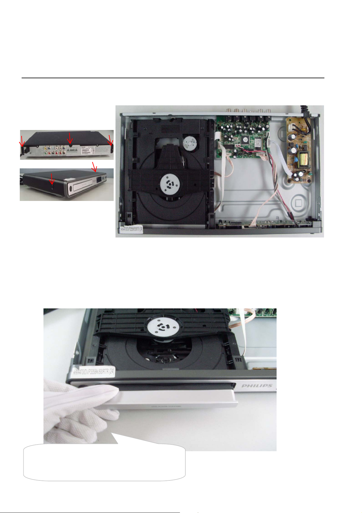
3-1
Mechanical and Dismantling Instructions
Dismantling Instruction
The following guidelines show how to dismantle the player.
Step1: Remove 5 screws around the Top Cover, and then remove the Top Cover (Figure 1).
Detailed information please refer to the model set.
Figure 1
Step2: If it is necessary to dismantle Loader or Front Panel, the Front door should be removed first. (Figure 2)
Note: Make sure to operate gently otherwise the guider would be damaged.
Please kindly note that dismantle the front door
assembly carefully to avoid damage tray and the front door.
Figure 2
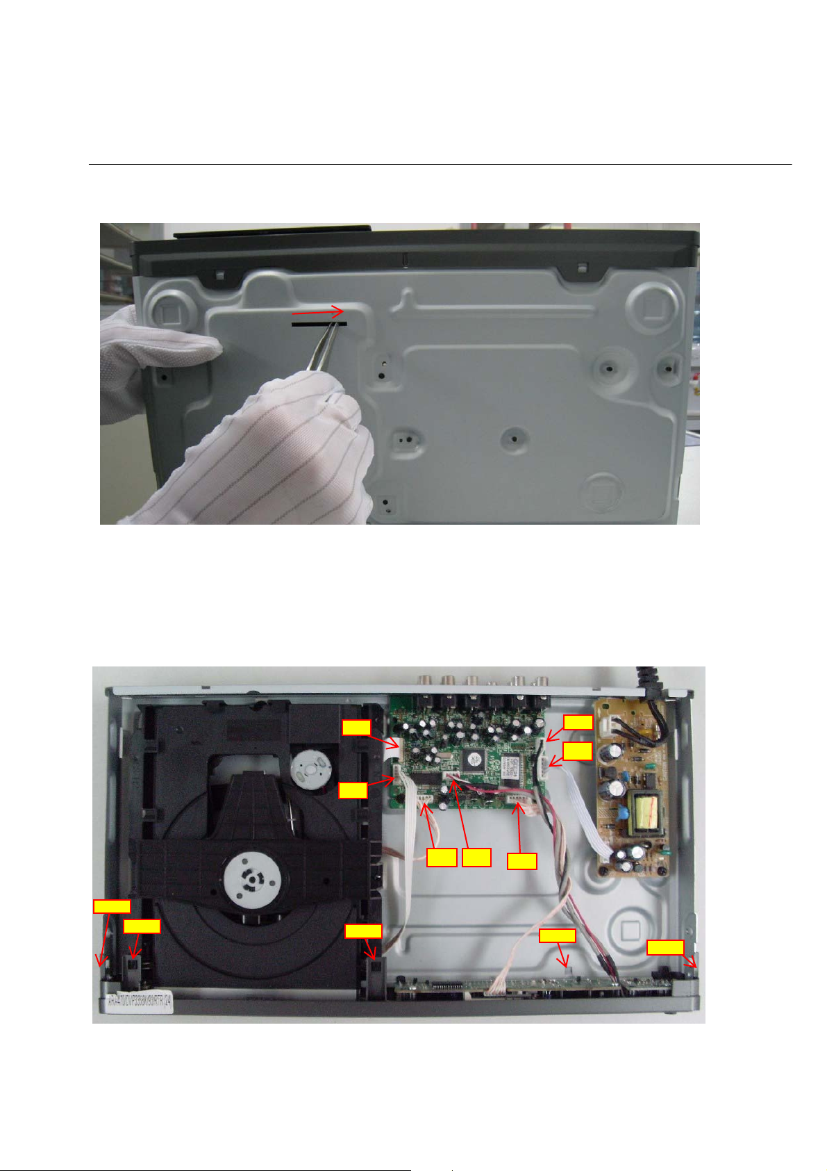
3-2
XP2
XP3
XP4
XP5
XP1
XP7
XP6
SNAP
SNAP
SNAP
SNAP
SNAP
Mechanical and Dismantling Instructions
Dismantling Instruction
Step3: If the tray can’t open in normal way, you can make it through the instruction as below (Figure 3).
Note: Make sure to operate gently otherwise the guider would be damaged.
Detailed information please refer to the model set.
Step4: Dismantling Front Panel, disconnect the connectors (XP5, XP6. XP7), need release 4 snaps of Front Panel
and 2 snaps of bottom cabinet , then gently pull the Panel out from the set. (Figure 4 - Figure 6)
Figure 3
Figure 4
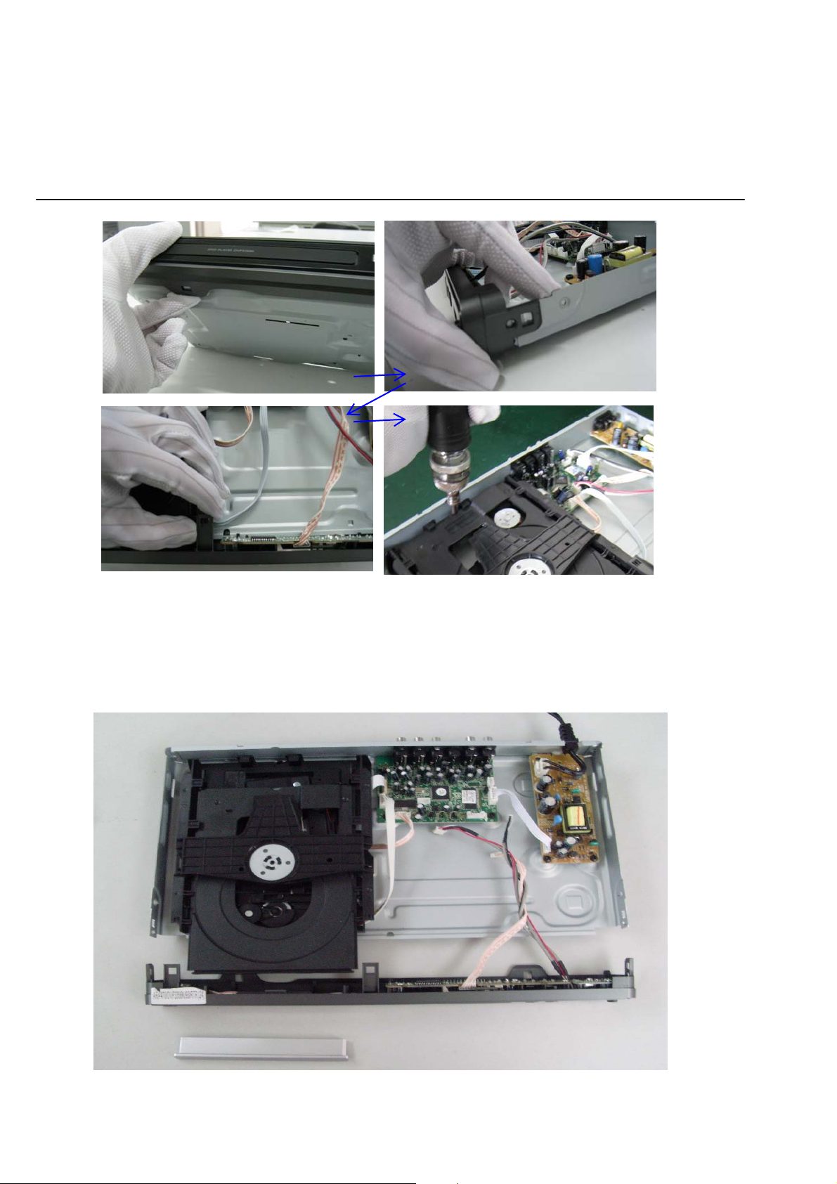
3-3
Mechanical and Dismantling Instructions
Dismantling Instruction
Detailed information please refer to the model set.
Figure 5
Step5: Dismantling Loader, disconnect the 3 connectors (XP2, XP3, XP4) aiming in the below figure, and remove 1 screw that
connects the loader and the bottom cabinet. (Figure 5 & 6)
Figure 6
3-4
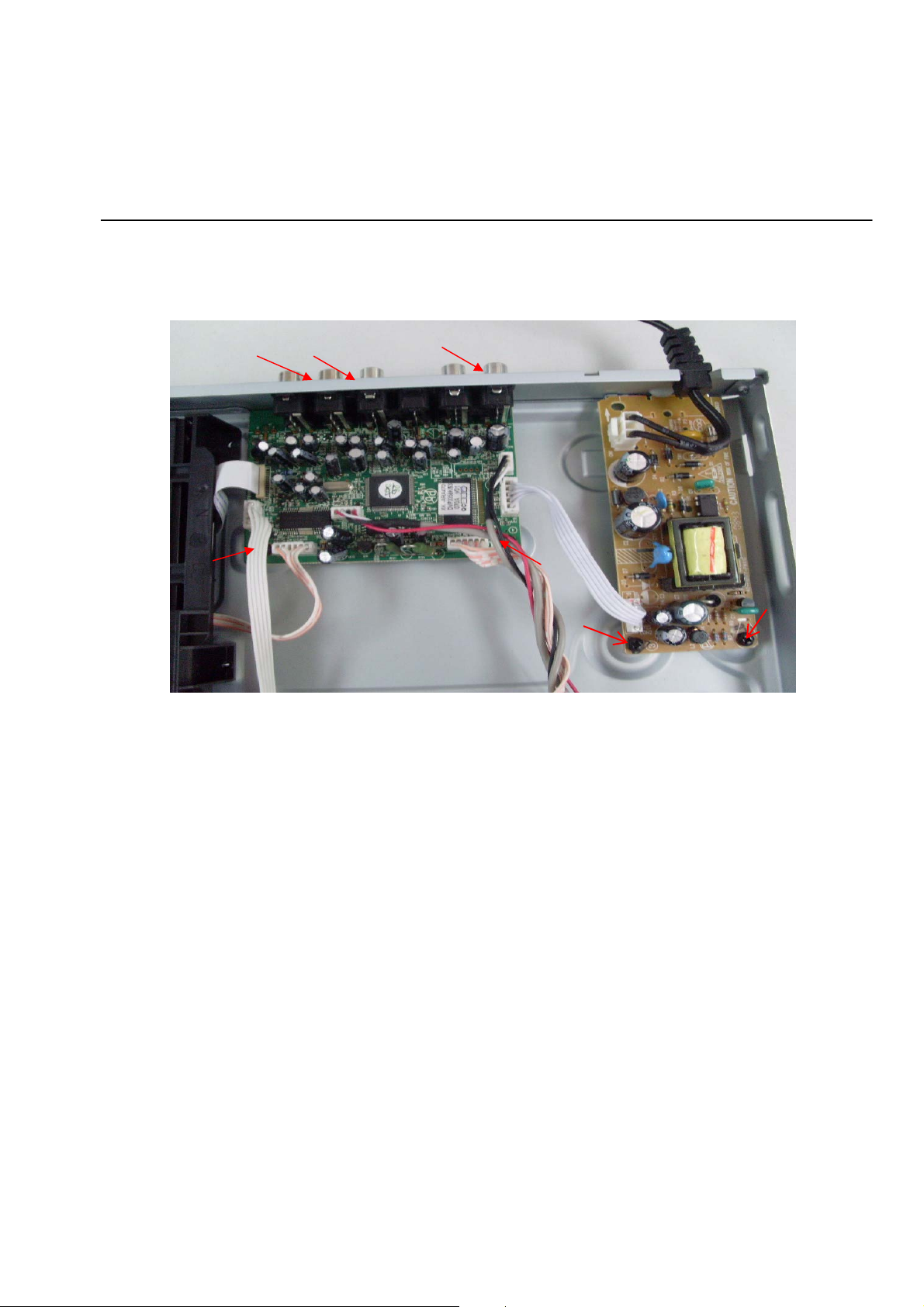
Mechanical and Dismantling Instructions
Dismantling Instruction
Step6: Dismantling Main Board, first disconnect the connector (XP1), and then remove 5 screws. (Figure 7)
Step7: Remove the 2 screws on Power Board to dismantle the Power Board. (Figure 7)
Detailed information please refer to the model set.
Figure 7

Software upgrade
4-1
Preparation to upgrade software
1) Start the CD Burning software and create a new CD
project (Data Disc) with the following setting:
Label: DVP3XXX (No need the label name)
File Name: DVPXX
Power on the set and open the tray, then press <5><5>
to check the File Name.
Note: It is required capital letter for the File System
name.
2) Burn the data onto a blank CDR
A. Procedure for software upgrade:
1) Power on the set and insert the prepared Upgrade
CDR.
2) The set will starts reading disc & response with the
following display TV screen:
Upgrade File DETECTED
Upgrade?
Press Play TO START.
3) Press <OK> button to confirm, then screen will display :
Files coping…
UPGRADING…
4) The upgraded tray will automatically open when files
coping complete, then take out the disc.
5) About 1 minute later, the trace will automatically close
when upgrading complete.
XX(K)_XX.BIN
*
B. Read out the software versions to confirm upgrading
1) Power on the set and press <Setup> button on the
remote control.
2) Press<1><3><7><9> button or press down cursor
on remote control to choose "Preference" and press
right & down cursors to choose "Version Info".
The software version and other information are display
on the TV screen as follows:
Model DVP33X
File Name DVP33X
Version XX.XX.XX.XX
RISC XX.XX.XX.XX
Servo XX.XX.XX.XX
Region Code X
HDCP PASS(except press<1><3><7><9>)
* The other upgrade SW way is by memory, the steps are the
same as CDR's, create the upgrade file into memory, and
connect the USB flash drive to the USB socket on set, then
press "USB" on remote control to access the content and
play the upgrade file as above upgrade procedure.
X(K) XX
X(K) XX.BIN
Caution: The set must not be power off during
upgrading, Otherwise the Main board will be
damaged entirely.
Region Code Change
1) Power on the set and open the tray door;
2) Press the "Setup" button on the remote control,then
the setup interface should be displayed on the TV screen;
3) Move the down cursor on remote control to choose "Reference"
and press "1" "3" "8" "9" "3" "1" on the remote control;
4) Then move the up or down cursors to choose the region code.
Note: restart after above steps.
 Loading...