

Philips DVP3030A, DVP3030A-94 User Manual

DVD Video Player
User manual
Visit us at www.philips.com/support for service support
DVP3030A
DVD622

General Information
Environmental Information
All unnecessary packaging has been
omitted. The packaging has been made
easy to separate into three materials:
cardboard (box), polystyrene foam
(buffer) and polyethylene (bags, protective
foam sheet).
Your DVD player consists of materials
which can be recycled and reused if
disassembled by a specialised company.
Please observe the local regulations
regarding the disposal of packaging
materials, exhausted batteries and old
equipment.
Laser safety
This unit employs a laser. Due to possible
eye injury, only a qualified service person
should remove the cover or attempt to
service this device.
NOTE:
PICTURES SHOWN MAYBE
DIFFERENT BETWEEN
COUNTRIES.
CAUTION
(WARNING LOCATION: ON THE
BACKPLATE OF THE SET)
NEVER MAKE OR CHANGE
CONNECTIONS WITH THE
POWER SWITCHED ON.
Important Note:
Due to the numerous versions of new
CD-Audio copy protection or
enhanced CD-Audio protection
recently available on certain discs,
Philips is unable to guarantee that
this DVD Player is fully compatible
with such new discs. Should you have
difficulty playing any such CD-Audio
discs, kindly refer them to your CDAudio disc retailer.
For Customer Use:
Read carefully the information located at
the bottom of your DVD VIDEO player
and enter below the Serial No. Retain this
information for future reference.
Model No. DVP3030A
Serial No. _______________
LASER
Type Semiconductor laser
GaAlAs
Wave length 650 nm (DVD)
780 nm (VCD/CD)
Output Power 7 mW (DVD)
10 mW (VCD/CD)
Beam divergence 60 degree

The apparatus shall not be exposed to dripping
or splashing and that no objects filled with
liquids, such as vases, shall be placed on
apparatus.
This product incorporates copyright
protection technology that is protected by
method claims of certain U.S. patents and
other intellectual property rights owned by
Macrovision Corporation and other rights
owners. Use of this copyr ight protection
technology must be authorized by
Macrovision Corporation, and is intended
for home and other limited viewing uses
only unless otherwise authorized by
Macrovision Corporation. Reverse
engineering or disassembly is prohibited.
Manufactured under license from Dolby
Laboratories. “Dolb y”, “Pro-Lo gic” and the
double-D symbol are trademarks of
Dolby Laboratories.
Due to the inconsistency of disc formats
Manufactured under license from Digital
provided by various disc manufacturers, your
Theater Systems, Inc. U.S. Pat. Nois .
DVD system may require a playability
5,451,942; 5,956,674; 5,974,380;
enhancement or upgrade. As DVD technology
5,978,762; 6,226,616; 6,487,535 and
other U.S. and world-wide patents issued
advances, these enhancements will become
and pending. "DTS" and "DTS Digital
common and will be easy to complete.
Surround" are registered trademarks
Go to www.philips.com/support for
of Digital Theater Systems, Inc.
software upgrade.
All Right Reserved.

Contents
Introduction
Supplied accessories ....................................... 5
Care and safety information..........................5
Connections
Connecting TV.............................................. 6-7
Using Composite Video jacks (CVBS)........ 6
Using S-Video jack.......................................... 6
Using Component Video jacks
(Y Pb Pr) ........................................................... 7
Using an accessory RF modulator .............. 7
Connecting the adaptor ................................. 8
Optional: Connecting speakers .................... 8
Optional : Connecting to an Audio System .
............................................................................. 9
Stereo system has Dolby Pro Logic or Right
/ Left Audio In jack ......................................... 9
Optional: Connecting Digital AV Receiver ...
............................................................................. 9
Receiver has a PCM, Dolby Digital, or
MPEG2 decoder.............................................. 9
Functional Overview
Front and Rear Panels ..................................10
Remote Control ............................................11
Getting Started
Step 1: Inserting batteries into the
Remote Control ............................................12
Using the Remote Control to operate the
Player............................................................... 12
Step 2: Setting up the TV........................12-13
To deactivate Progressive manually.......... 12
Selecting the colour system that
corresponds to your TV..............................13
Setting the TV Display ................................. 13
Step 3: Setting language preference ...........14
Setting the OSD Language..........................14
Setting the Audio, Subtitle and DVD menu
language .......................................................... 14
Disc Operations
Playable Discs .................................................15
Region Codes .................................................15
Power resume ................................................ 16
Playing discs.....................................................16
Using Disc Menu............................................16
Basic playback controls........................... 17-18
Pausing playback............................................17
Selecting track/chapter................................ 17
Resuming playback from the last stopped
point ................................................................ 17
Zoom .............................................................. 17
Repeat ............................................................. 17
Repeat A-B ..................................................... 17
Slow Motion .................................................. 18
Forward / Reverse Searching ..................... 18
Preview ........................................................... 18
Special disc features ......................................19
Selecting a Title ............................................. 19
Camera Angle ................................................19
Changing the Audio Language .................... 19
Subtitles .......................................................... 19
Playing MP3/JPEG Picture CD...............19-20
General Operation.......................................19
Playback selection.........................................20
Repeat ............................................................. 20
Zoom picture ................................................20
Playback with multi-angles.......................... 20
Scan Effect ......................................................20
DVD Menu Options
Language ..........................................................21
OSD Menu .....................................................21
Audio, Subtitle, DVD Menu ........................ 21
Video Setup...............................................21-22
TV Display...................................................... 21
TV T ype ........................................................... 21
Setting the Video Output ............................ 22
Progressive – turning on/off.......................22
Audio Setup ..............................................23-24
Digital Output ............................................... 23
LPCM Output................................................ 24
Night Mode - turning on/off.......................24
Rating..........................................................25-26
Changing the Password............................... 25
Setting the Rating ......................................... 26
Restoring to original settings..................... 26
Specifications ......................................27
Troubleshooting......................... 28–29
Glossary ......................................................................30
4
3139 246 15972
Introduction
10 cm
(4 inches)
10 cm
(4 inches)
10 cm
(4 inches)
PHILIPS
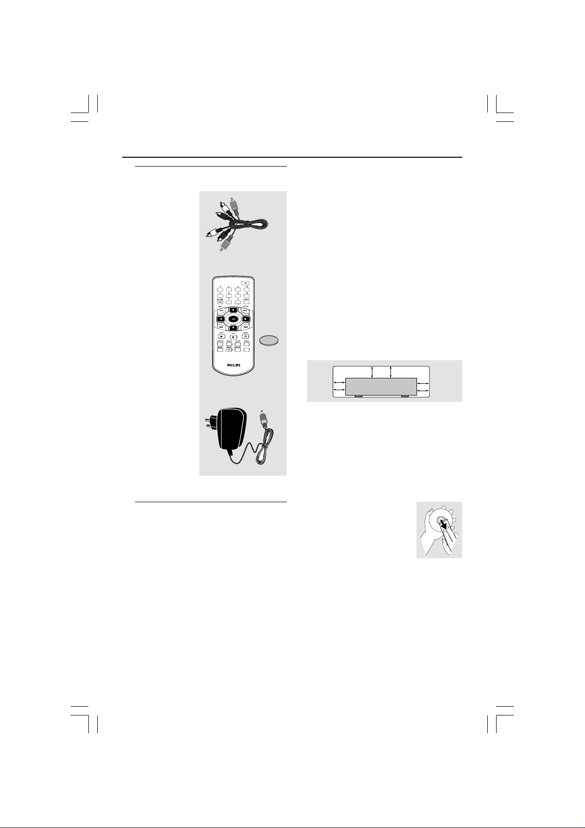
Supplied accessories
Composite video
cable (yellow) /
Audio cable
(white, red)
Remote Control
and
battery (lithium
CR2025)
VOLUME
12V DC Adaptor
Care and safety information
● Power consumption
– When the system is switched to
Standby mode, it is still consuming power.
To disconnect the system from the power
supply completely, remove the 12V DC
Adaptor plug from the wall jack.
● Avoid high temperatures, moisture,
water and dust
– Do not expose the player, batteries or
discs to humidity, rain, sand or excessive
heat (caused by heating equipment or
direct sunlight.)
● Avoid condensation problem
– The lens may cloud over when the
player is suddenly moved from cold to
warm surroundings, making it impossible
to play a disc. Leave the player in the
warm environment until the moisture
evaporates.
● Do not block the vents
– Do not operate the DVD Player in an
C
R
2
0
2
5
L
I
T
H
I
U
M
enclosed cabinet, allow about 10 cm (4
inch) of free space all around the player
for adequate ventilation.
● Care of the cabinet
– Use a soft cloth slightly moistened with
a mild detergent solution. Do not use a
solution containing alcohol, spirits,
ammonia or abrasives.
● Finding a suitable location
– Place the player on a flat, hard, and
stable surface.
● Disc handling
– To clean a CD, wipe it in a
straight line from the center
towards the edge using a soft,
lint-free cloth. A cleaning
agent may damage the disc!
– Write only on the printed
side of a CDR(W) and only with a soft felttipped pen.
– Handle the disc by its edge, do not
touch the surface.
5
3139 246 15972

Connections
AUDIO
IN
V (Pr/Cr)
U (Pb/Cb)
Y
S-VIDEO
IN
VIDEO IN
COMPONENT
VIDEO IN
AUDIO
OUT
V (Pr/Cr)
U (Pb/Cb)
Y
S-VIDEO
IN
VIDEO IN
COMPONENT
VIDEO IN
1
2
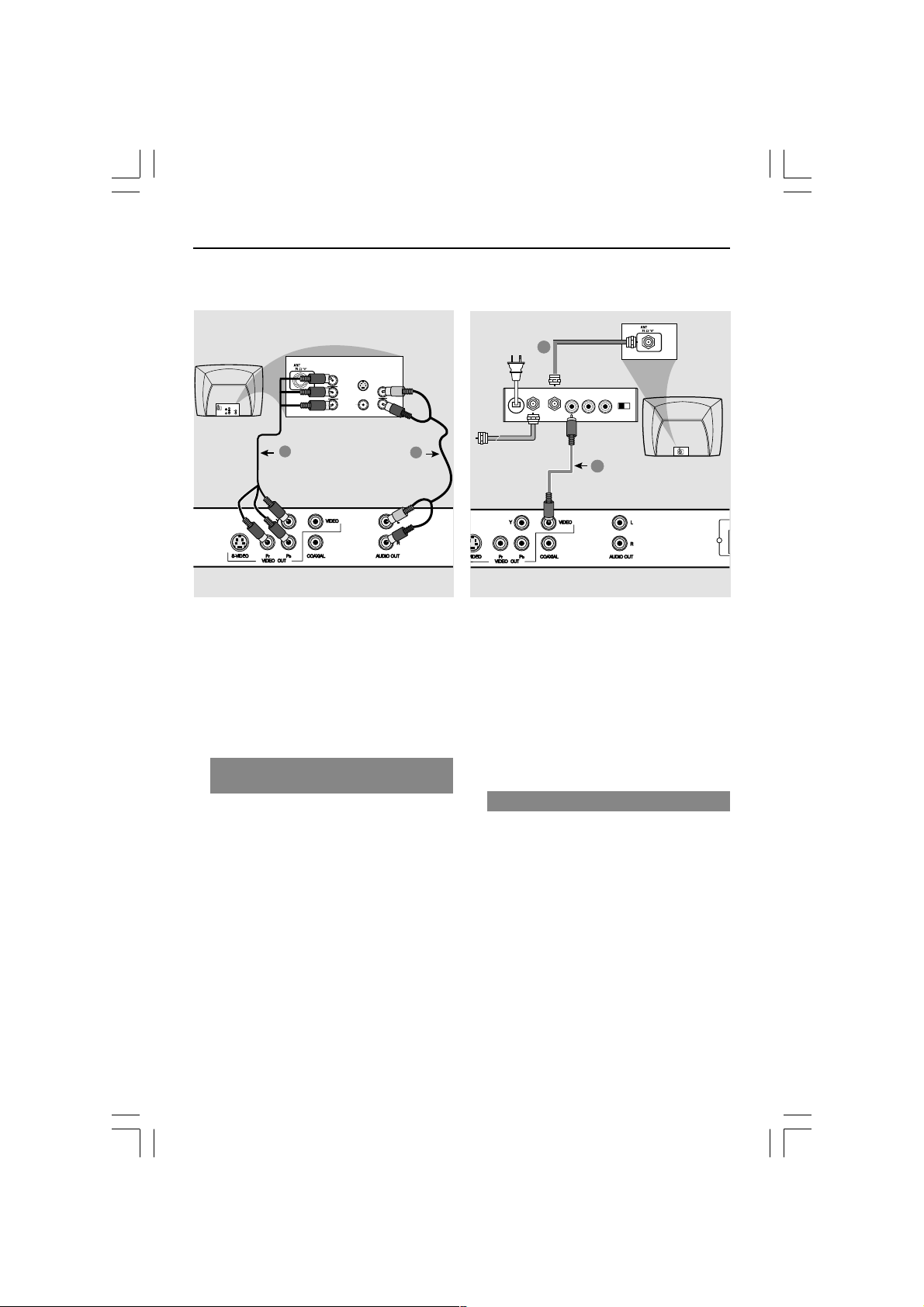
Connecting TV
COMPONENT
VIDEO IN
S-VIDEO
IN
V (Pr/Cr)
AUDIO
OUT
U (Pb/Cb)
VIDEO IN
Y
COMPONENT
VIDEO IN
V (Pr/Cr)
U (Pb/Cb)
Y
S-VIDEO
VIDEO IN
IN
AUDIO
IN
1
2
IMPORTANT!
– You only need to make
one video
connection from the following
options, depending on the
capabilities of your TV system.
– Connect the DVD system directly
to the TV.
Using Composite Video jacks
(CVBS)
1 Use the composite video cable (yellow) to
connect the DVD Player’s CVBS (VIDEO)
jack to the video input jack (or labeled as
A/V In, Video In, Composite or Baseband)
on the TV (cable supplied).
2 To hear the sound of this DVD Player
through your TV, use the audio cables
(white/red) to connect AUDIO OUT (L/
R) jacks of the DVD Player to the
corresponding AUDIO IN jacks on the TV
(cable supplied).
IMPORTANT!
– S-Video connection provides
better picture quality. This option
must be available on your TV.
Using S-Video jack
1 Use the S-video cable to connect the
DVD system’s S-VIDEO OUT jack to
the S-Video input jack (or labeled as Y/C
or S-VHS) on the TV (cable not supplied).
2 To hear the sound of this DVD Player
through your TV, use the audio cables
(white/red) to connect AUDIO OUT (L/
R) jacks of the DVD Player to the
corresponding AUDIO IN jacks on the TV
(cable supplied).
6
3139 246 15972
Connections
AUDIO IN
R L
VIDEO
IN
TO TVINT IN
CH3 CH4
2
1
RF coaxial cable to TV
COMPONENT
VIDEO IN
S-VIDEO
IN
V (Pr/Cr)
AUDIO
IN
U (Pb/Cb)
COMPONENT
VIDEO IN
S-VIDEO
IN
V (Pr/Cr)
AUDIO
OUT
U (Pb/Cb)
VIDEO IN
Y
VIDEO IN
Y
Back of RF Modulator
(example only)
1
2
IMPORTANT!
– Component Video connection
provides higher picture quality. This
option must be available on your TV.
– The progressive scan video
quality is only possible through
Component Video (Y Pb Pr) output.
Using Component Video jacks
(Y Pb Pr)
1 Use the component video cables (green/
blue/red) to connect the DVD system’s Y
Pb Pr jacks to the corresponding
Component video input jacks (or labeled
as Y Pb Pr) on the TV (cable not supplied).
2 To hear the sound of this DVD Player
through your TV, use the audio cables
(white/red) to connect AUDIO OUT (L/
R) jacks of the DVD Player to the
corresponding AUDIO IN jacks on the TV
(cable supplied).
Antenna or
Cable TV signal
IMPORTANT!
– If your TV only has a single
Antenna In jack (or labeled as 75
ohm or RF In,) you will need an RF
modulator in order to view the DVD
playback on the TV. See your
electronics retailer or contact for
details on RF modulator availability
and operations.
Using an accessory RF modulator
1 Use the composite video cable (yellow) to
connect the DVD Player’s CVBS jack to
the video input jack on the RF modulator.
2 Use the RF coaxial cable (not supplied) to
connect the RF modulator to your TV’s
RF jack.
3139 246 15972
7
Connections
12 mm
abc
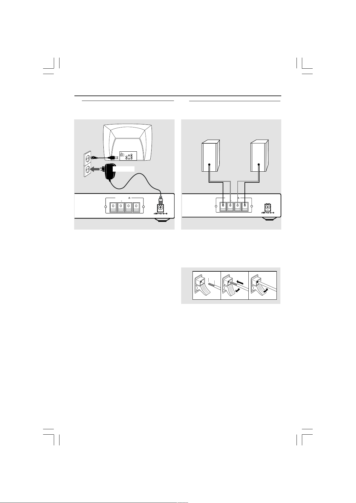
Connecting the adaptor
COMPONENT
VIDEO IN
S-VIDEO
S-VIDEO
IN
IN
V (Pr/Cr)
AUDIO
SCART/RGB IN
AUDIO
IN
OUT
~ AC MAINS
U (Pb/Cb)
VIDEO IN
VIDEO IN
Y
12V ADAPTOR
SPEAKERS (6 )
RIGHT+LEFT
– +
After everything is connected
properly, plug in the 12V Adaptor to
the power outlet.
Never make or change any connections
with the power switched on.
Optional: Connecting speakers
Front
Right
SPEAKERS (6 )
RIGHT+LEFT
Connect the speaker wires to the right
speaker to “RIGHT” and left speaker to
“LEFT”, colored red wire to “+” and
black wire to “–”.
– +
Front
Left
Helpful Hints:
– Ensure that the speaker cables are
correctly connected. Improper connections
may damage the system due to short-circuit.
– Please refer to the SPECIFICATIONS
section of this manual for speaker
impedence ratings.
8
3139 246 15972
Connections
RIGHT
+
SPEA
AUDIO
IN
COAXIAL
OPTICAL
AV Receiver
+
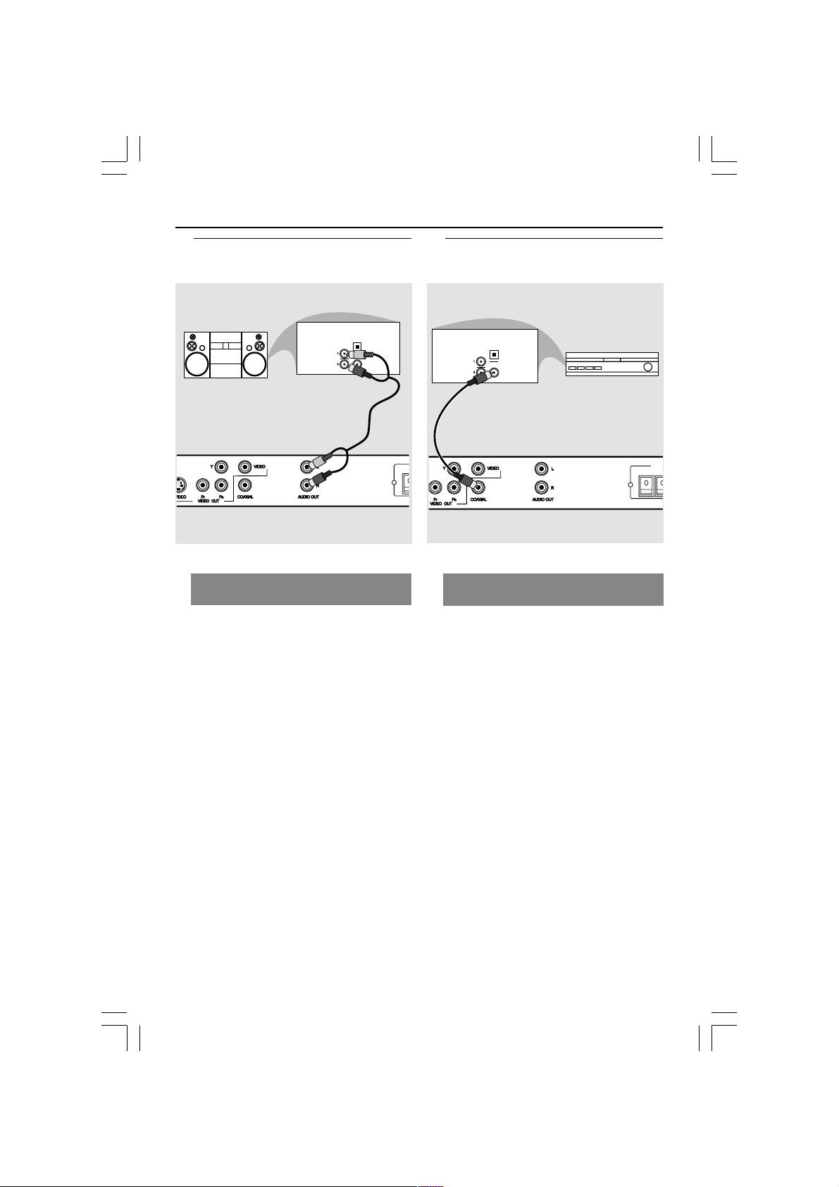
Optional: Connecting to an
Audio System
STEREO
Stereo system has Dolby Pro Logic
or Right / Left Audio In jack
OPTICAL
AUDIO
IN
DIGITAL
1 Select one of the video connections
(CVBS VIDEO IN, S-VIDEO IN,
COMPONENT VIDEO IN) depending on
the options available on your TV.
2 Use the audio cables (white/red) to
connect AUDIO OUT (L/R) jacks of
the DVD Player to the corresponding
AUDIO IN jacks on the stereo system
(cable supplied).
Optional: Connecting Digital AV
Receiver
Receiver has a PCM, Dolby Digital,
or MPEG2 decoder
1 Select one of the video connections
(CVBS VIDEO IN, S-VIDEO IN,
COMPONENT VIDEO IN) depending on
the options available on your TV.
2 Connect the COAXIAL jack of the DVD
Player to the corresponding Digital Audio
In jack on your Receiver (cable not
supplied).
3 Set the DVD Player’s Digital Output to
PCM or ALL depending on the capabilities
of your Receiver (see page 23 “Digital
Output”).
Helpful Hint:
– If the audio format of the Digital Output
does not match the capabilities of your
receiver, the receiver will produce a strong,
distorted sound or no sound at all.
9
3139 246 15972
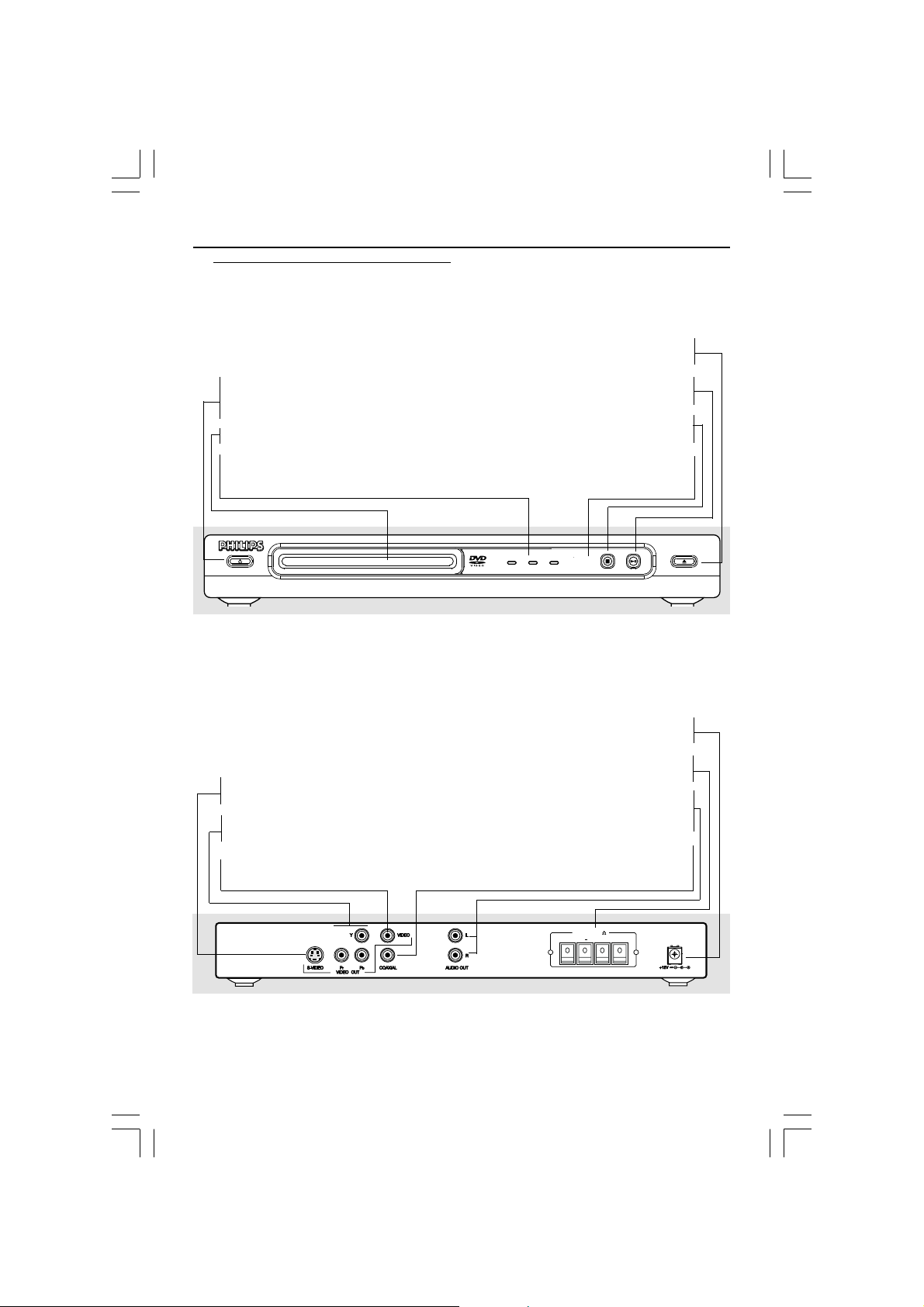
Functional Overview
Front and Rear Panels
STANDBY-ON B
– To switch the DVD Player to Standby
mode or ON
Disc tray
LEDs
– Shows the current status of the D VD
Player
OPEN/CLOSE /
– Open/Close the disc tray
2; PLA Y/PAUSE
– To start or interrupt playback
9 STOP
– To stop playback
IR Sensor
– Point the remote control to war ds this
sensor
STANDBY-ON
S-Video Out
– Connect to S-Video input of a TV
YPbPr
– Connect to YPbPr input of a TV
CVBS (VIDEO Out)
– Connect to CVBS Video input of a TV
PLAY/PAUSE
STOP
OPEN/CLOSE
12Volts DC Input
– Connect to an external adaptor
Speaker connectors
– Connect to Front Left and Right speakers
Audio Out (Left/Right)
– Connect to AUDIO inputs of an amplifier,
receiver or stereo system
COAXIAL (Digital audio out)
– Connect to coaxial AUDIO input of a
digital audio equipment
SPEAKERS (6 )
RIGHT+LEFT
– +
Caution: Do not touch the inner pins of the jacks on the rear panel.
Electrostatic discharge may cause permanent damage to the unit.
10
3139 246 15972
 Loading...