

Page 1
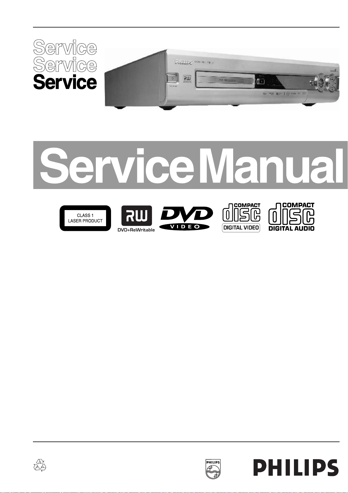
DVD-Video Recorder DVDR70 & DVDR75/0x1
Contents Page Contents Page
1 Technical Specifications and Connection
Facilities
Diversity Matrix 2
PCB Locations 5
2 Safety Information, General Notes 6
3 Directions for Use 8
4 Mechanical Instructions 45
5 Diagnostic Software 49
6
Block Diagrams, Waveforms, Wiring Diagram
Wiring Diagram 92
Waveforms 93
Testpoints 97
7
Circuit Diagrams and PWB Layouts
Display Panel (Diagram 1) 102
Front Connector (FC) (Diagram 2) 103
Standby Panel (STBY) (Diagram 3) 107
Tray Left Panel (TRL) (Diagram 4) 108
Tray Right Panel (TRR) (Diagram 5) 109
Analog Board:Fronted Video (FV) (Diagram 1) 110
Analog Board: In / Out Video (IOV) (Diagram 2) 111
Analog Board: In / Out Audio (IOA) (Diagram 3) 112
An. Brd for VAE8020: Power Supply (PS)(Diagram 4) 113
An. Brd for VAD8031: Power Supply (PS) (Diagram 5) 114
Analog Board: Multi Sound Processing (MSP)
Analog Board: VPS (Diagram 6) 116
Analog Board: Follow Me (FOME) (Diagram 7) 116
Analog Board: Digital In/Out (DIGIO) (Diagram 8) 117
Analog Board: Audio Converter 603 3033 (DAC_ADC)
Analog Board: Audio Converter 603 3028 (DAC_ADC)
©
Copyright 2002 Philips Consumer Electronics B.V. Eindhoven, The Netherlands.
All rights reserved. No part of this publication may be reproduced, stored in a
retrieval system or transmitted, in any form or by any means, electronic,
mechanical, photocopying, or otherwise without the prior permission of Philips.
(Diagram 5)
(Diagram 9)
(Diagram 10)
2
89
102
115
118
119
UP Sub Board: Central Controler (CECO)
UP Sub Board: Fan Control (FACO) (Diagram 12) 129
DVIO Board: 1394 Interface (Diagram 1) 132
DVIO Board: Link + Codec (Diagram 2) 133
DVIO Board: uP Part (Diagram 3) 134
DVIO Board: Interface + DAC (Diagram 4) 135
DVIO Board: Clock (Diagram 5) 136
Digital Board 1.5: VSM Buffer Memory and Bit Engine
Interface (Diagram 1)
Digital Board 1.5: AV Dec. STI5519 (Diagram 2) 141
Digital Board 1.5: AV Decoder Mem. (Diagram 3) 142
Digital Board 1.5: Video Enc. Empress (Diagram 4) 143
Digital Board 1.5: VIP CVBS Y/C Video Input
Digital Board 1.5: Analog Board Cons. Video In/Out
Digital Board 1.5: Progressive Scan (Diagram 7) 146
Digital Board 1.5: Progressive Scan (Diagram 8) 147
Digital Board 1.5: Power, Clock and Reset (Diagram 9) 148
DB Chrysalis 2.1: IDE, UARTS, RESET, BE(Diagram 1) 155
DB Chrysalis 2.1: 1394 (Diagram 2) 156
DB Chrysalis 2.1: Audio PLL (Diagram 3) 157
DB Chrysalis 2.1: Chrysalis (Diagram 4) 158
DB Chrysalis 2.1: 1.8V Power (Diagram 5) 159
DB Chrysalis 2.1: Prog. scan DAC (Diagram 6) 160
DB Chrysalis 2.1: Flash SDRAM EEPROM(Diagram 7) 161
DB Chrysalis 2.1: Video IO (Diagram 8) 162
DB Chrysalis 2.1: VIPs (Diagram 9) 163
8 Alignments 167
9 Circuit-, IC Descriptions and List
of Abbreviations
10 Spare Parts List 246
11 Revision List 260
For service manual of Basic Engine VAE8020 please refer to 3122 785 12473.
For service manual of Basic Engine VAD8031 please refer to 3122 785 13680.
(Diagram 11)
(Diagram 5)
(Diagram 6)
128
140
144
145
170
Published by GH 0393 Service PaCE Printed in the Netherlands Subject to modification EN 3122 785 13322
Page 2
EN 2 DVDR70 & DVDR75/0x11.
Technical Specifications and Connection Facilities
1. Technical Specifications and Connection Facilities
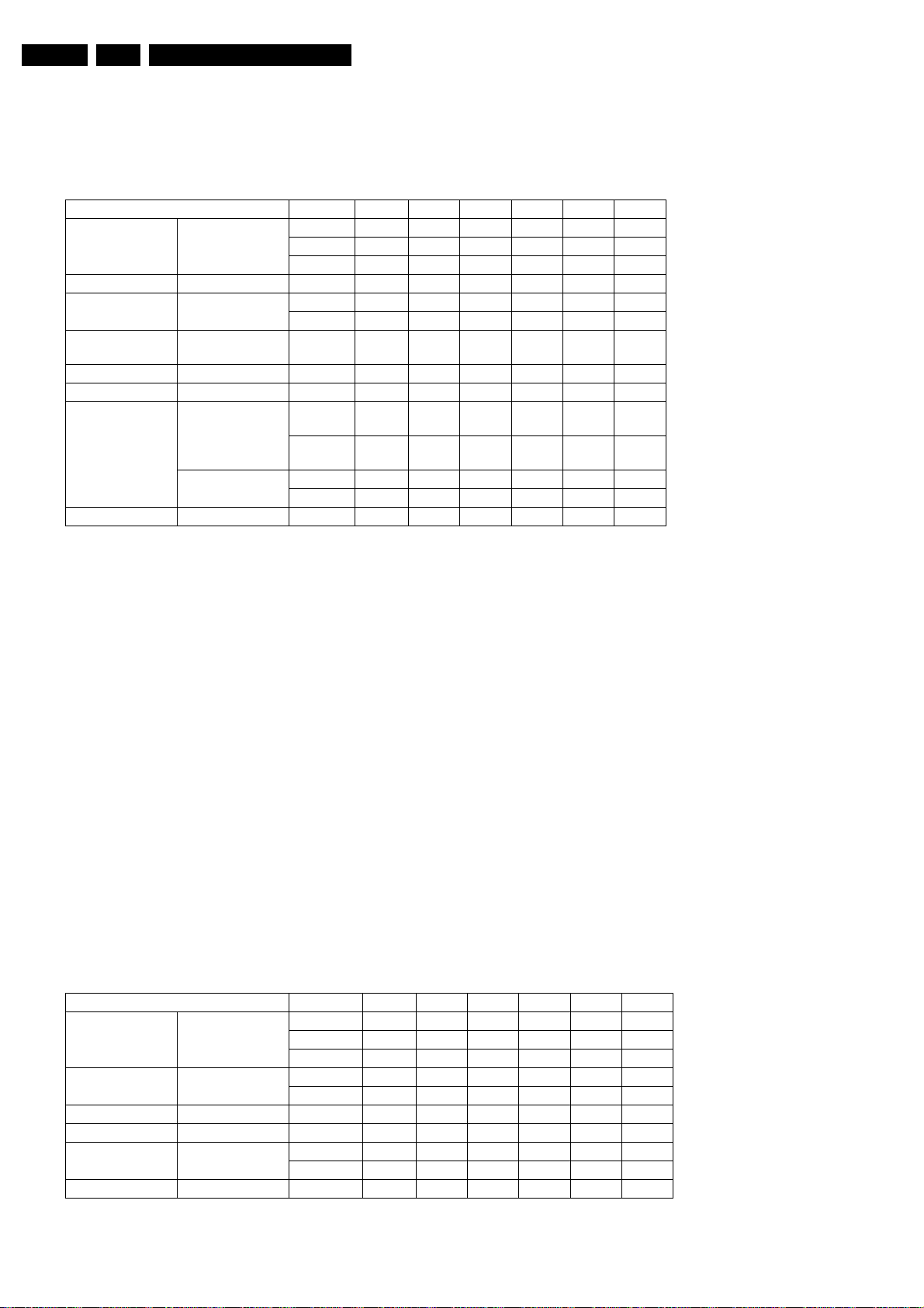
1.1 Diversity Matrix for sets with drive VAE8020 (AV2)
Type DVDR 75/001 75/021 75/051 70/001 70/021 70/051
Version
A' Lead X X X
A Lead X X X
DVIO DVIO 1.8 <VN05 <VN05 <VN05
Digital Board
(Chrysalis) 2.1
Digital Board
(Empress) 1.5
Basic Engine VAE 8020 XXXXXX
UP Sub AL E1 X X X X X X
3103 603 3033
Analog-Board
3103 603 3028
Display Board DC1 AL X X X X X X
E1 >VN04 >VN04 >VN04
E2 >VN04 >VN04 >VN04
E1 <VN05 <VN05 <VN05 <VN05 <VN05 <VN05
AL
E2/PS
AL
E1/PS
AL E2 >VN03 >VN03
AL E1 >VN02 >VN03 >VN02 >VN03
<VN03 <VN04 <VN03 <VN04
<VN04 <VN04
Remarks:
<VN03 ... This module is used in sets with production codes VN01 and VN02. Please see the type plate of the set for the production code.
>VN02 ... This module is used in sets with production code VN03 and higher.
E1 ... Digital Board Chrysalis Version Euro 1 for sets with DV input
E2 ... Digital Board Chrysalis Version Euro 2 for sets without DV input
AL E1/PS ... Analog Board version A-Lead Euro 1, used from production start onwards.
AL E2/PS ... Analog Board version A-Lead Euro 2 for UK, used from Production Start onwards.
The Analog Board versions "AL Ex/PS" are based on the PWB layout code 3103 603 3033.
This layout code can also be seen on the underside of the Analog Board in the copper near the power supply part.
AL E1 ... Analog Board version A-Lead Euro 1 replaces "AL E1/PS" at a certain production date.
AL E2 ... Analog Board version A-Lead Euro 2 for UK replaces "AL E2/PS" at a certain production date.
The Analog Board versions "AL Ex" are based on the PWB layout code 3103 603 3028.
The main difference to the Analog Board used at production start is the used audio digital/analogue converter; see Analog Board circuit
diagram 9.
1.2 Diversity Matrix for sets with drive VAD8031 (AV3)
Sets with VAD8031 can be identified by the production code
starting with VN1A, (then VN1B, VN1C...) and by the presence
of a set fan.
Type DVDR 75/001 75/021 75/051 70/001 70/021 70/051
Version
A' Lead X X X
A Lead X X X
Digital Board
(Chrysalis) 2.1
BasicEngine VAD 8031 X X X X X X
UP Sub AL E1/AV3 X X X X X X
Analog-Board
Display Board DC1 ALXXXXXX
use PWB drawing
603 3028
E1 /AV3 X X X
E2 /AV3 X X X
AL E2/AV3 X X
AL E1/AV3 X X X X
Page 3

Technical Specifications and Connection Facilities
EN 3DVDR70 & DVDR75/0x1 1.
1.3 General:
Mains voltage : 198V-276V
Mains frequency : 43 Hz - 63Hz
Power consumption mains : 28 W
Power consumption standby : < 7 W
Power consumption low power
stand-by : < 3 W
1.4 RF Tuner
Test equipment:Fluke 54200 TV Signal generator
Test streams:PAL BG Philips Standard test pattern
1.4.1 System:
PAL B/G, PAL D/K, SECAM L/L’, PAL I
1.4.2 RF - Loop Through:
Frequency range : 45 MHz - 860 MHz
Gain: (ANT IN - ANT OUT) : -6 dB to 0dB
1.4.3 Radio Interference:
input voltage /3 tone method (+40
dB min) : no limit
1.4.4 Receiver:
PLL tuning with AFC for optimum reception
Frequency range: : 45.25 MHz - 857 MHz
Sensitivity at 40 dB S/N : ≥ 60dBµV at 75Ω
(video unweighted )
1.4.5 Video Performance:
Channel 25 / 503,25 MHz,
Test pattern: PAL BG PHILIPS standard test pattern,
RF Level 74 dBV
Measured on SCART 1
Frequency response: : 0 - 4.00 MHz +0-4dB
Group delay ( 0.1 MHz - 4.4 MHz ) : 0 nsec ± 150nsec
1.4.6 Audio Performance:
Audio Performance Analogue - HiFi:
Frequency response at SCART 1
(L+R) output: : 100 Hz - 12 kHz / 0±
3dB
S/N according to DIN 45405, 7, 1967 :
and PHILIPS standard test pattern
video signal: : FM: ≥ 50dB; AM ≥
45dB, unweighted
Harmonic distortion ( 1 kHz, ± 25
kHz deviation ): : FM ≤ 1.5%; AM ≤ 2%
Audio Performance NICAM:
Frequency response at SCART
1(L+R) output: : 40 Hz - 15 kHz 0 ±
3dB
S/N according to DIN 45405, 7, 1967 :
and PHILIPS standard test pattern
video signal: : ≥ 60 dB unweighted
Harmonic distortion (1 kHz): : ≤ 0.5 %
1.4.7 Tuning
Automatic Search Tuning
scanning time without antenna : typ. 3 min. PAL
stop level (vision carrier) : ≥ 37dBµV
Maximum tuning error of a recalled
program : ± 62.5 kHz
Maximum tuning error during
operation : ± 100 kHz
Tuning Principle
automatic B,G, I, DK and L/L’detection
manual selection in "STORE" mode
1.5 Analogue Inputs
1.5.1 SCART 1 (Connected to TV)
Pin Signals:
1 - Audio R 1.8V RMS
2 - Audio R
3 - Audio L 1.8V RMS
4 - Audio GND
5 - Blue/Chroma
GND
6 - Audio L
7 - Blue out/
Chroma in 0.7Vpp ± 0.1V into 75 Ohm (*)
8 - Function
switch <2V = TV
>4.5V / <7V = asp. ratio 16:9 DVD
>9.5V / <12V = asp. ratio 4:3 DVD
9 - Green GND
10 - P50 control
11 - Green 0.7Vpp ± 0.1V into 75 Ohm (*)
12 - Nc
13 - Red/Chroma
GND
14 - fast switch
GND
15 - Red out/
Chroma out 0.7Vpp ± 0.1V into 75 Ohm (*)
± 3dB 0.3Vpp Chroma (burst)
16 - fast switch
RGB/ CVBS or Y <0.4V into 75 Ohm = CVBS
>1V / <3V into 75 Ohm = RGB
17 - Y/CVBS GND
OUT
18 - Y/CVBS GND
IN
19 - CVBS/Y 1Vpp ± 0.1V into 75 Ohm (*)
20 - CVBS/Y
21 - Shield
1.5.2 SCART 2 (Connected to AUX)
Pin Signals:
1 -Audio R 1.8V RMS
2 -Audio R
3 -Audio L 1.8V RMS
4 -Audio GND
5 -Blue/Chroma
GND
6 -Audio L
7 -Blue in/
Chroma out ± 3dB 0.3Vpp Chroma (burst)
8 -Function
switch
9 -Green GND
10 -P50 control
11 -Green
12 -Nc
13 -Red/Chroma
GND
14 -fast switch
GND
15 -Red in/
Chroma in
Page 4

EN 4 DVDR70 & DVDR75/0x11.
Technical Specifications and Connection Facilities
16 -fast switch
RGB/ CVBS or
Y
17 -CVBS GND
OUT
18 -CVBS GND
IN
19 -CVBS/Y/RGB
sync 1Vpp ± 0.1V into 75 Ohm (*)
20 -CVBS/Y
21 -Shield
(*) for 100% white
1.5.3 Audio/Video Front Input Connectors
Audio
Input voltage : 2 Vrms
Input impedance : >10kΩ
Video - Cinch
Input voltage : 1 Vpp ± 3dB
Input impedance : 75 Ω
Video - YC (Hosiden)
Input voltage Y : 1Vpp ± 3dB
Input impedance Y : 75 Ω
Input voltage C : burst 300 mVpp ± 3
dB
Input impedance C : 75 Ω
1.6 Video Performance
All outputs loaded with 75 Ohm
SNR measurements over full bandwidth without weighting.
1.6.1 SCART (RGB)
SNR : > -65 dB on all output
Bandwidth : 4.8 MHz ± 2dB
Intermodulation distortion : >70dB
Mute (spin-up, pause, access) : >85dB
Outband attenuation: : >40dB above 25kHz
1.8 Digital Output
1.8.1 Coaxial
CDDA/ LPCM (incl MPEG1) : according IEC958
MPEG2, AC3 audio : according IEC1937
DTS : according IEC1937,
amendment 1
1.9 Digital Video Input (IEEE 1394)
1.9.1 Applicable Standards
Implementation according:
IEEE Std 1394-1995
IEC 61883 - Part 1
IEC 61883 - Part 2 SD-DVCR (02-01-1997)
Specification of consumer use digital VCR’s using 6.3 mm
magnetic tape - dec.1994
Mechanical connection according:
Annex A of 61883-1
1.10 P50 System Control
Via SCART pin nr 10
1.11 Dimensions and Weight
Height of feet : 10mm
Apparatus tray closed : WxDxH :435 x 324.5 x
88cm
Apparatus tray open : WxDxH :435 x 366 x
88cm
Weight without packaging : app. 4 kg ± 0.5 kg
Weight in packaging : app. 6.5 kg
1.7 Audio Performance CD
1.7.1 Cinch Output Rear
Output voltage 2 channel mode : 2Vrms ± 2dB
Channel unbalance (1kHz) : <1dB
Crosstalk 1kHz : >95dB
Crosstalk 20Hz-20kHz : >85dB
Frequency response 20Hz- 20kHz : ±0.2dB max
Signal to noise ratio : >95 dB
Dynamic range 1kHz : >85dB
Dynamic range 20Hz-20kHz : >80dB
Distortion and noise 1kHz : >85dB
Distortion and noise 20Hz-20kHz : >75dB
Intermodulation distortion : >77dB
Mute : >95dB
Outband attenuation: : >40dB above 30kHz
1.7.2 Scart Audio
Output voltage 2 channel mode : 1.6Vrms ± 2dB
Channel unbalance (1kHz) : <1dB
Crosstalk 1kHz : >85dB
Crosstalk 20Hz-20kHz : >70dB
Frequency response 20Hz- 20kHz : ± 0.2dB max
Signal to noise ratio : >85 dB
Dynamic range 1kHz : >75dB
Dynamic range 20Hz-20kHz : >70dB
Distortion and noise 1kHz : >75dB
Distortion and noise 20Hz-20kHz : >65dB
1.12 Laser Output Power & Wavelength
1.12.1 DVD
Output power during reading : 0.8mW
Output power during writing : 20mW
Wavelength : 660nm
1.12.2 CD
Output power : 0.3mW
Wavelength : 780nm
Page 5
Technical Specifications and Connection Facilities
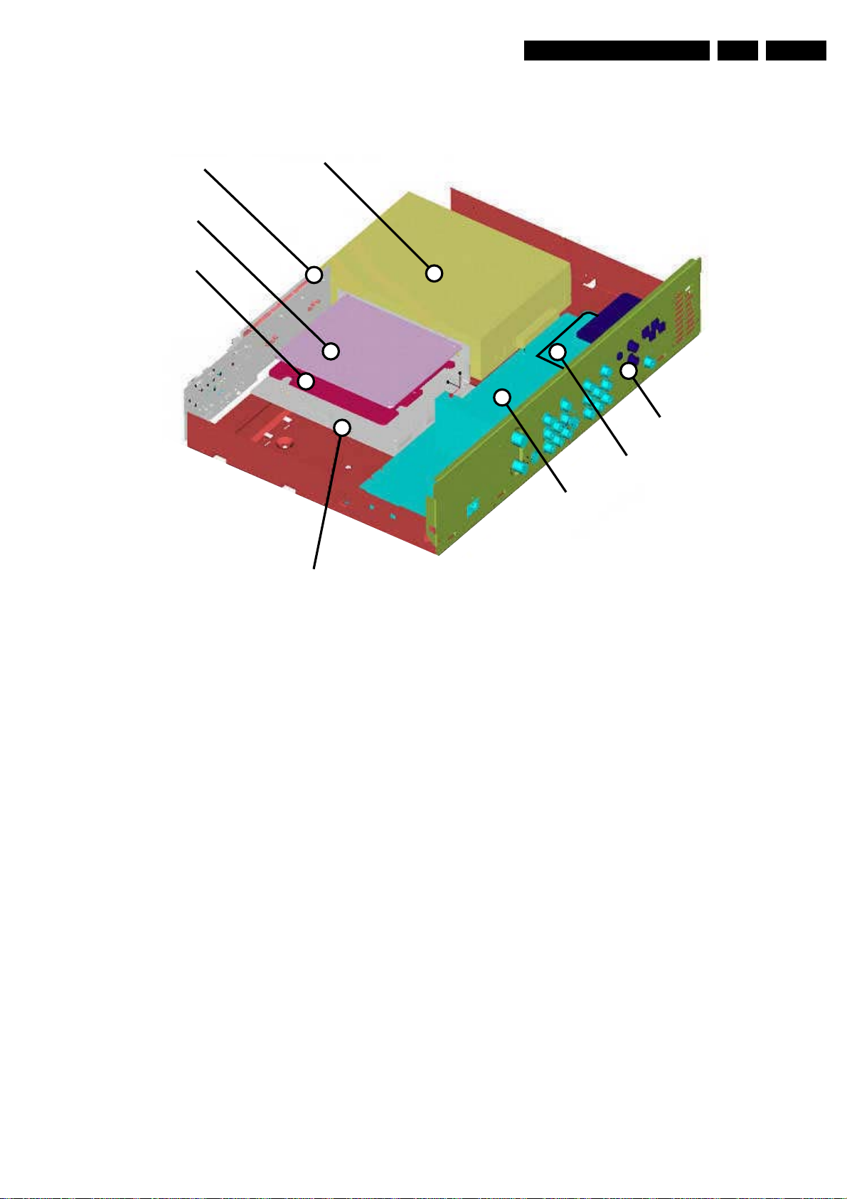
1.13 PCB Locations
EN 5DVDR70 & DVDR75/0x1 1.
Display Board
EPG Board
DVIO Board
Basic Engine
IOE Board
Up Sub Board
Analog Board
Digital Board
Remarks:
The EPG Board and the In/Out Extension Board IOE are only
used in the DVDR80.
The DVIO Board is only present in the DVDR75 and only in
combination with the Digital Board 1.5 (Empress). It is not
present in DVDR75 with Digital Board 2.1 (Chrysalis).
TR 06002_001
300103
Page 6
EN 6 DVDR70 & DVDR75/0x12.
Safety Information, General Notes
2. Safety Information, General Notes
2.1 Safety Instructions
2.1.1 General Safety
Safety regulations require that during a repair:
• Connect the unit to the mains via an isolation transformer.
• Replace safety components, indicated by the symbol ,
only by components identical to the original ones. Any
other component substitution (other than original type) may
increase risk of fire or electrical shock hazard.
Safety regulations require that after a repair, you must return
the unit in its original condition. Pay, in particular, attention to
the following points:
• Route the wires/cables correctly, and fix them with the
mounted cable clamps.
• Check the insulation of the mains lead for external
damage.
• Check the electrical DC resistance between the mains plug
and the secondary side:
1. Unplug the mains cord, and connect a wire between
the two pins of the mains plug.
2. Set the mains switch to the 'on' position (keep the
mains cord unplugged!).
3. Measure the resistance value between the mains plug
and the front panel, controls, and chassis bottom.
4. Repair or correct unit when the resistance
measurement is less than 1 MΩ.
5. Verify this, before you return the unit to the customer/
user (ref. UL-standard no. 1492).
6. Switch the unit ‘off’, and remove the wire between the
two pins of the mains plug.
2.1.2 Laser Safety
This unit employs a laser. Only qualified service personnel may
remove the cover, or attempt to service this device (due to
possible eye injury).
2.2 Warnings
2.2.1 General
• All ICs and many other semiconductors are susceptible to
electrostatic discharges (ESD, ). Careless handling
during repair can reduce life drastically. Make sure that,
during repair, you are at the same potential as the mass of
the set by a wristband with resistance. Keep components
and tools at this same potential.
Available ESD protection equipment:
– Complete kit ESD3 (small tablemat, wristband,
connection box, extension cable and earth cable) 4822
310 10671.
– Wristband tester 4822 344 13999.
• Be careful during measurements in the live voltage section.
The primary side of the power supply (pos. 1005), including
the heatsink, carries live mains voltage when you connect
the player to the mains (even when the player is 'off'!). It is
possible to touch copper tracks and/or components in this
unshielded primary area, when you service the player.
Service personnel must take precautions to prevent
touching this area or components in this area. A 'lightning
stroke' and a stripe-marked printing on the printed wiring
board, indicate the primary side of the power supply.
• Never replace modules, or components, while the unit is
‘on’.
2.2.2 Laser
• The use of optical instruments with this product, will
increase eye hazard.
• Only qualified service personnel may remove the cover or
attempt to service this device, due to possible eye injury.
• Repair handling should take place as much as possible
with a disc loaded inside the player.
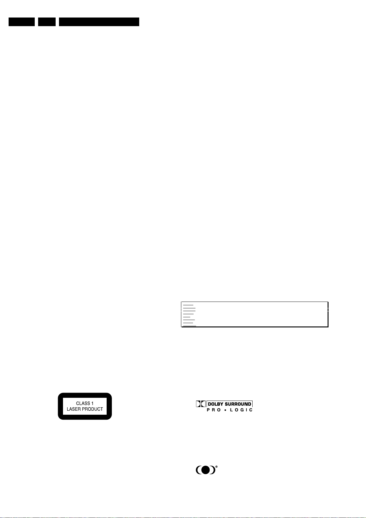
• Text below is placed inside the unit, on the laser cover
shield:
Laser Device Unit
Type : Semiconductor laser
GaAlAs
Wavelength : 650 nm (DVD)
: 780 nm (VCD/CD)
Output Power : 20 mW
(DVD+RW writing)
: 0.8 mW
(DVD reading)
: 0.3 mW
(VCD/CD reading)
Beam divergence : 60 degree
Figure 2-1
Note: Use of controls or adjustments or performance of
procedure other than those specified herein, may result in
hazardous radiation exposure. Avoid direct exposure to beam.
CAUTION VISIBLE AND INVISIBLE LASER RADIATION WHEN OPEN AVOID EXPOSURE TO BEAM
ADVARSEL SYNLIG OG USYNLIG LASERSTRÅLING VED ÅBNING UNDGÅ UDSÆTTELSE FOR STRÅLING
ADVARSEL SYNLIG OG USYNLIG LASERSTRÅLING NÅR DEKSEL ÅPNES UNNGÅ EKSPONERING FOR STRÅLEN
VARNING SYNLIG OCH OSYNLIG LASERSTRÅLNING NÄR DENNA DEL ÄR ÖPPNAD BETRAKTA EJ STRÅLEN
VARO! AVATTAESSA OLET ALTTIINA NÄKYVÄLLE JA NÄKYMÄTTÖMÄLLE LASER SÄTEILYLLE. ÄLÄ KATSO SÄTEESEEN
VORSICHT SICHTBARE UND UNSICHTBARE LASERSTRAHLUNG WENN ABDECKUNG GEÖFFNET NICHT DEM STRAHL AUSSETSEN
DANGER VISIBLE AND INVISIBLE LASER RADIATION WHEN OPEN AVOID DIRECT EXPOSURE TO BEAM
ATTENTION RAYONNEMENT LASER VISIBLE ET INVISIBLE EN CAS D'OUVERTURE EXPOSITION DANGEREUSE AU FAISCEAU
!
Figure 2-2
2.2.3 Notes
Dolby
Manufactered under licence from Dolby Laboratories. “Dolby”,
“Pro Logic” and the double-D symbol are trademarks of Dolby
Laboratories. Confidential Unpublished Works.
©1992-1997 Dolby Laboratories, Inc. All rights reserved.
Figure 2-3
Trusurround
TRUSURROUND, SRS and symbol (fig 2-4) are trademarks of
SRS Labs, Inc. TRUSURROUND technology is manufactured
under licence frm SRS labs, Inc.
Figure 2-4
Page 7

Safety Information, General Notes
Video Plus
“Video Plus+” and “PlusCode” are registered trademarks of the
Gemstar Development Corporation. The “Video Plus+” system
is manufactored under licence from the Gemstar Development
Corporation.
Figure 2-5
Macrovision
This product incorporates copyright protection technology that
is protected by method claims of certain U.S. patents and other
intellectual property rights owned by Macrovision Corporation
and other rights owners.
Use of this copyright protection technology must be autorized
by Macrovision Corporation, and is intended for home and
other limited viewing uses only unless otherwise authorized by
Macrovision Corporation. Reverse engineering or disassembly
is prohibited.
EN 7DVDR70 & DVDR75/0x1 2.
Page 8
3. Directions For Use
EN 8 DVDR70 & DVDR75/0x13.
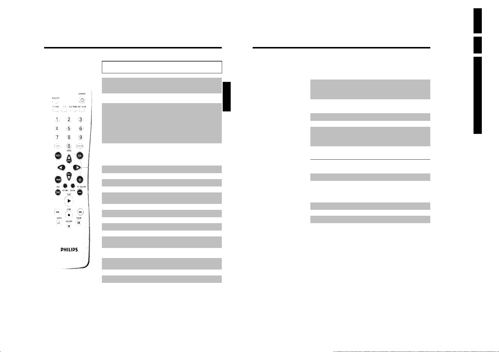
The remote control
MONITOR Monitor: This button lets you switch between the TV receiver (internal
STANDBY m Switch on or off: To switch set on or off, interrupt menu function,
TV/DVD TV/DVD switch: Switches the scart socket EXT 2 AUX-I/O directly
T/C Title/Chapter: Choose the '
PLAY MODE Playback type: Choose between repeat, shuffle play and intro-scan
REC MODE Record type (quality): To select the maximum possible record time
0..9 Number buttons:0-9
DISC-MENU Disc menu: To show the DVD menu or the index screen
SYSTEM-MENU System menu: Call up/cancel the main menu (menu bar at the top of
SELECT Select: Select function/value
OK Store/confirm: To store or confirm entry
DC Cursor keys : Cursor left, right
CH+ A Cursor buttons/Plus : Cursor up/ Next programme number
CH- B Cursor buttons/Minus : Cursor down / Previous programme number
TIMER TIMER: To make a TIMER programming with ShowView
FSS & EDIT: For displaying the edit menu for DVD+R(W) discs, for setting
RETURN Back: Return to previous menu on a video CD (VCD). This also works
CLEAR Delete: To delete last entry or clear programmed recording (TIMER)
PLAY G Playback: To play a recorded disc.
tuner) in the DVD recorder (TV picture on the TV set) and playback on
the DVD recorder.
interrupt a programmed recording (TIMER)
to the TV set. This lets you watch the picture from any unit connected
to this scart socket (set-top box', video recorder or satellite receiver)
and at the same time record from another source.
If you have not connected a device to the EXT 2 AUX-I/O socket, use
this button to switch between TV reception and the DVD recorder.
But this only works if you use a scart cable to connect the TV set to
your DVD recorder ( EXT 1 TO TV-I/O socket) and your TV set
responds to this switch-over.
'(Title)/'C'(Chapter) directly from the
menu bar
If 'INFO' appears in the display, the index menu from a recorded disc or
an introductory film will be shown. In this case, this function is not
available.
the screen)
®
ShowView
or to alter or clear a programmed TIMER
chapter markers
with some DVDs.
B
®
/without
ENGLISH
N Select previous title/search backwards :
O Select next title/search forwards :
STOP h Stop: Stop playback/recording, except with programmed recordings
AUDIO Audio: Select the audio language. For recording language 1 or 2
REC/OTR n Record: Record the current TV channel
PAUSE 9 Pause (still picture): If this button is pressed during playback, the
Briefly press the button during playback: Previous chapter/film or
previous title
Hold down the button: Search backwards
Hold down button during still picture, slow motion backwards
Briefly press the button during playback: Next chapter/film or next title
Hold down the button: Search forwards
Hold down button during still picture, slow motion forwards
(TIMER)
Hold down button, opens and closes the disc tray.
DVD recorder switches to pause. You will see a still picture.
If this button is pressed during recording, the DVD recorder will also
switch to pause.
Additional TV functions
This will only work with TV sets with the same remote control code *RC5) (e.g. Philips TV sets)
TV VOLUME q TV volume: Increase TV volume
TV VOLUME r TV volume: Reduce TV volume
For the following functions you need to hold down the button at the side DVD/TV and then
select the function you need with the appropriate button.
STANDBY m Switching the TV off:
0..9 Number buttons:0-9
CH+ A TV programme number: To select a higher programme number
CH- B TV programme number: To select a lower programme number
Directions For Use
Page 9
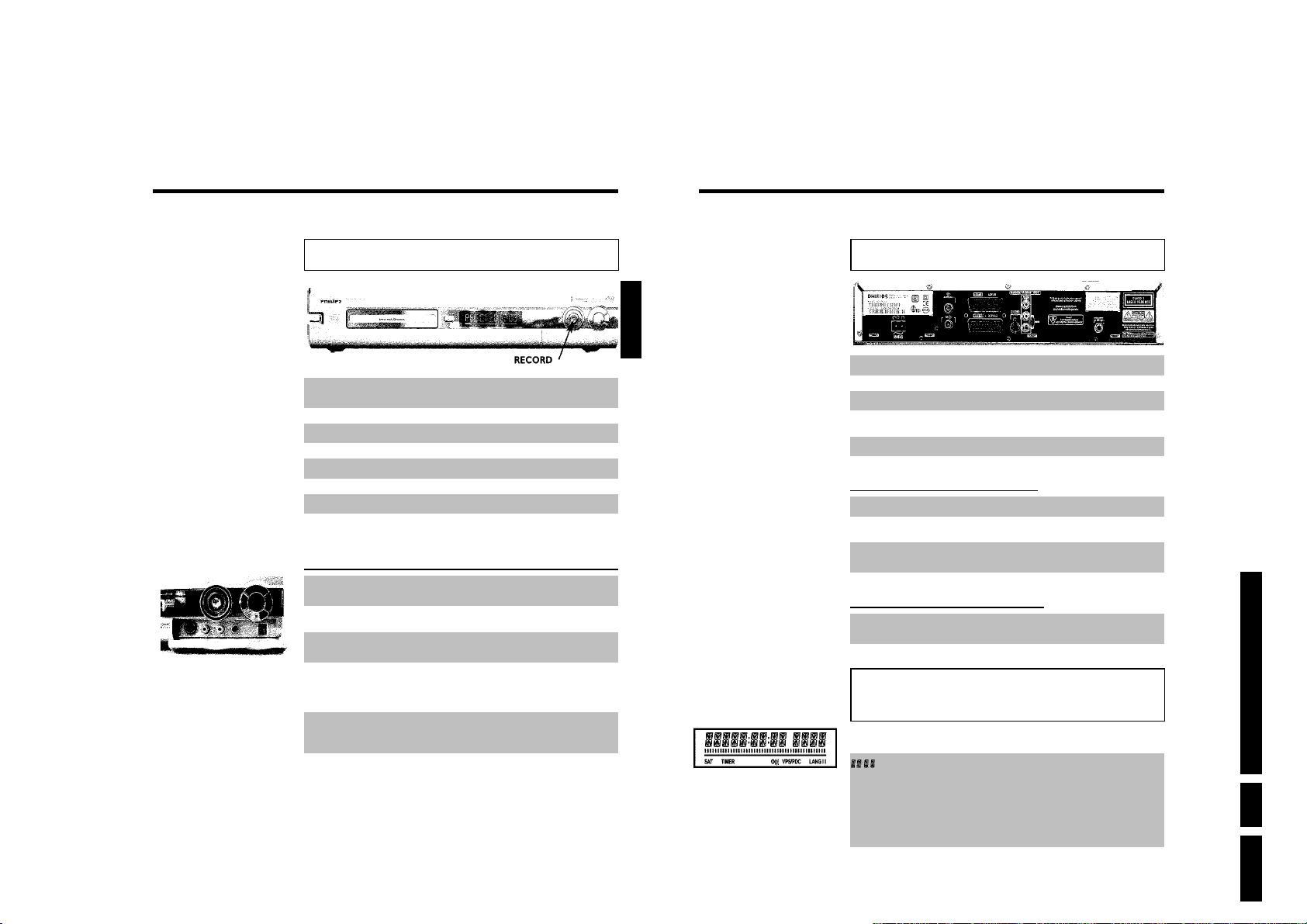
Front of the device
STANDBY/ON m Switch on or off: To switch off or on, interrupt a function, interrupt a
OPEN/CLOSE J Open/close disc tray: Open/close disc tray
RECORD Record: Record the current TV channel
G Playback: To play a recorded disc
N Select previous title/search backwards
O Select next title/search forwards
h Stop: Interrupt playback/recording
programmed recording (TIMER)
Behind the flap at the righthand corner on
the front
S-VIDEO SVideo socket: Connection of SVHS/Hi8 camcorders or SVHS/Hi8
Yellow socket
VIDEO
White/red socket
left AUDIO right
video recorders (programme number 'CAM1')
Video input socket: Connection of camcorders or video recorders
(programme number 'CAM1')
Audio input socket left/right : Connection of camcorders or video
recorders (programme number 'CAM1')
ENGLISH
Back of the unit
4MAINS Mains socket: Connection to the mains supply (230V/50Hz)
ANTENNA IN Aerial input: Connection of the aerial
TV OUT Aerial output: Connection of the TV set
EXT 2 AUX-I/O Scart socket 2: Connection of an additional device (satellite receiver,
EXT 1 TO TV-I/O Scart socket 1: Connection of a TV set. RGB output
Output sockets (AUDIO/VIDEO OUT)
OUT S-VIDEO (Y/C) SVideo output: Connection of an S-Video-compatible TV set
OUT VIDEO
(CVBS)
OUT L AUDIO R Analogue audio output (white/red socket): Connection of a TV
Output socket (DIGITAL AUDIO OUT)
DIGITAL AUDIO
OUT
set-top box, video recorder, camcorder, etc.)
Video output (yellow socket): Connecting a TV set with a video
input (CVBS, Composite Video)
set with audio input sockets or connection of an additional device
Digital audio output: Connection of a digital audio device
(amplifier/receiver)
Directions For Use
Switching between the S-VIDEO and VIDEO sockets takes place automatically. If both sockets
are in use, the signal at the S-VIDEO socket has priority.
DV IN iLink/DV socket (digital video input, IEEE 1394, FireWire):
Connecting a digital camcorder or other suitable device (programme
number 'CAM2').
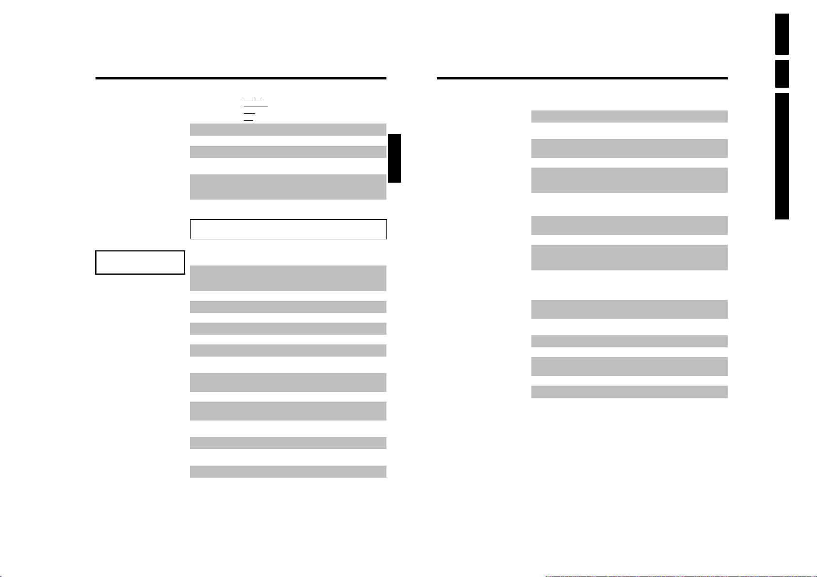
The symbols on your DVD recorder
display
These symbols can light up on your DVD recorder display:
Multi-function display/text line
•) Clock
•) Disc/title playing time
•) OTR switch-off time
•) Title name
•) Display of the programme number of the TV channel/playing
time/channel name/function.
•) Display of information and alerts
EN 9DVDR70 & DVDR75/0x1 3.
Page 10
EN 10 DVDR70 & DVDR75/0x13.
READING
IIIIIIIIIIIIIII
SAT
TIMER
o(((
VPS/PDC
LANG II
Disc bar: Displays the current position on the disc (disc pointer).
Play/Record: Single flashing segment at the current position.
Pause: Flashing segment on both sides of the current position.
Stop: Illuminated segment at the current position.
A satellite recording has been programmed.
A recording (timer) has been programmed
A remote control signal has been received
Video programming system / programme delivery control: A VPS or
PDC code will be transmitted for the selected TV program
During playback a HiFi/2 channel tone was detected or a HiFi/2 channel
tone was received. 'I' or 'II' lights up depending on which sound channel
has been selected
Messages in the DVD recorder display
The following messages may appear in your DVD recorder display
IS TV ON? The DVD recorder is in initial installation mode. Switch the TV on, then
NO SIGNAL No input signal available (signal inadequate or unstable)
MENU The menu on the screen is active
OPENING Disc tray opening
TRAY OPEN Disc tray open
CLOSING Disc tray closing
READING Disc being read
MENU UPDT Once recording has been successfully completed the table of contents is
INIT MENU The menu structure is created after the first recording has been made
COPY PROT You have tried to copy a copy-protected DVD/video cassette.
WAIT Please wait until this message disappears. The DVD recorder is busy
NO DISC A disc has not been inserted for recording. If a disc has been inserted, it
INFO
BUSY The DVD recorder is processing the changes to make them DVD
ERASING The entire disc is erased
read the paragraph on 'Initial installation' in 'Installing your DVD
recorder'.
created.
on a new disc
performing a task.
cannot be read.
Information about the inserted DVD is displayed on the screen
compatible
ENGLISH
EMPTYDISC The disc inserted is either new or has been completely erased (no
PROTECTED The disc is protected against recording.
MAX TITLE The maximum number of titles per disc has been reached. The
MAX CHAP The maximum number of chapters per title/disc has been reached. The
DISC FULL The disc is full. There is no space for new recordings
PAL DISC A disc with PAL recordings has been inserted. The machine is trying to
NTSC DISC A disc with NTSC recordings has been inserted. The machine is trying
RECORDING An illegal action (e.g. OPEN/CLOSE J button) was attempted during
FREETITLE Playback was started for an empty title or the following title is empty.
DISC LOCK An attempt has been made to record during playback of a protected
DISC ERR An error occurred when writing the title. If this error keeps occurring,
DISC WARN An error occurred when writing the title. Recording was continued; the
SETUP After the automatic search the menu for setting the date/time will
WAIT 01 During the automatic search the TV channels found are counted
BLOCKED The disc tray cannot be closed/opened.
SAFE REC The new recording will be added at the end of all the other recordings
EASYLINK Data is being transferred from the 'EasyLink' TV.
POST-FORMAT Post format
recordings).
maximum number of titles per disc is 48.
maximum number of chapters per title is 124.
record an NTSC signal. Insert a new disc or one that contains NTSC
recordings.
to record a PAL signal. Insert a new disc or one that contains PAL
recordings.
recording.
disc. This message appears if an attempt is made to insert a chapter
marker ( FSS & button).
please clean the disc or use a new one.
For instructions on how to clean a disc see the section on 'Cleaning the
discs' in the next chapter.
error was skipped
appear on the screen.
(SAFE RECORD).
Directions For Use
Page 11
B
Connecting the DVD recorder
Preparing the remote control for
operation
The remote control and its batteries are packed separately in the original DVD recorder
packaging. You must install the batteries in the remote control before use - described in the
following section.
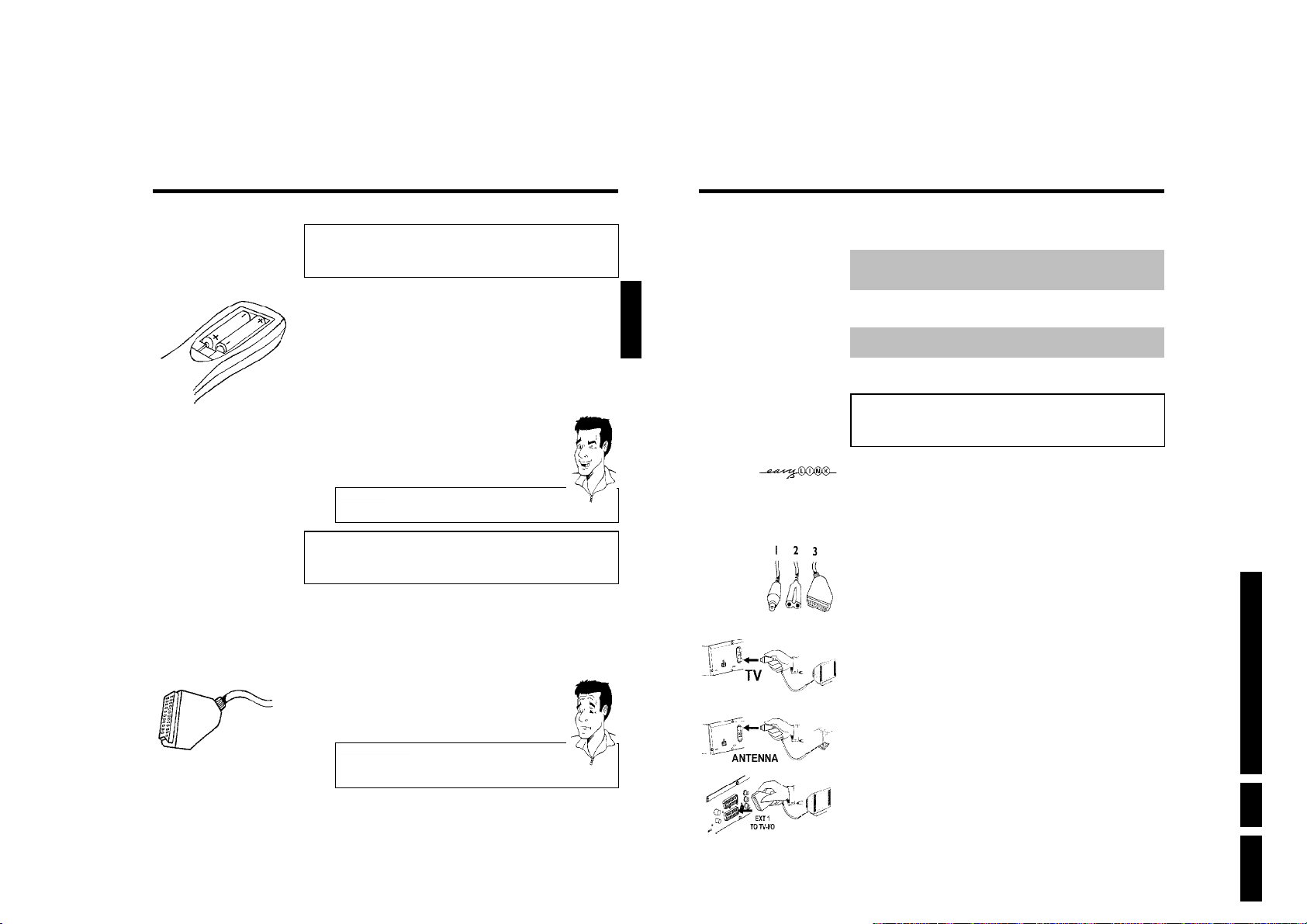
1 Take the remote control and the enclosed batteries (2 batteries).
2 Open the battery compartment, insert the batteries as shown and
then close the battery compartment.
The remote control is now ready to use.
Its range is approximately 5 to 10 meters.
'Aim' correctly
In the following sections, you will need the remote control for the first time.
Aim the remote control at the DVD recorder and not at the TV set.
Tip
Connecting your DVD recorder to the TV
set
The necessary cable connections must be made before you can record or playback TV
programmes using your DVD recorder.
Connect the DVD recorder directly to your TV set. If there is a video recorder in between
the picture quality may be poor.
We recommend that you use a scart cable to connect your TV set and DVD recorder.
ENGLISH
When you install your DVD recorder for the first time, select one of the following options:
'Connecting with a scart cable and Easy Link'
If your TV set is equipped with 'Easy Link, Cinema Link, NexTView Link, Q-Link, Smart Link,
Megalogic, Datalogic, ...' and you wish to use a scart cable.
'Connecting with a scart cable without Easy Link'
If your TV set is not equipped with 'Easy Link, Cinema Link, NexTView Link, Q-Link, Smart Link,
Megalogic, Datalogic, ...' and you wish to use a scart cable.
'Connecting with an SVideo(Y/C)cable'
If your TV set is equipped with an S-Video(SVHS) socket.
'Connecting with video(CVBS) cable'
If your TV set is equipped only with an video(CVBS) socket.
Connecting with a scart cable and
'Easy Link'
Your DVD recorder can exchange information with your TV set using 'Easy Link'. Your TV
channels can also be transferred in the same order from your TV set to your DVD recorder
using 'Easy Link'.
Please see your TV's operating instructions.
Have the following cables ready:
an aerial cable (1, supplied), a mains cable (2, supplied), a special scart cable (3, suitable for
Easylink).
1 Switch off your TV set.
2 Remove the aerial cable plug from your TV set. Insert it into the
ANTENNA IN socket at the back of the DVD recorder.
Directions For Use
Connecting the DVD recorder
What is a scart cable?
The scart or Euro AV cable serves as the universal connector for picture,
sound and control signals. With this type of connection, there is practically no
loss of quality in picture or sound transmission.
3 Insert one end of the supplied aerial cable into the TV OUT socket at
the back of the DVD recorder and the other end into the aerial input
socket at the back of the TV set.
?
4 Plug in a special scart cable (for Easylink) into the scart socket EXT 1
TO TV-I/O at the back of the DVD recorder and the corresponding
scart socket at the back of the TV set (see TV set operating
instructions).
EN 11DVDR70 & DVDR75/0x1 3.
11
12
Connecting the DVD recorder
Page 12
EasyLink
loading data from TV;
please wait
Audio Language
English
Español
Français
English
Italiano
Press OK to continue
Virgin mode
5 Switch on the TV set.
6 Insert one end of the supplied mains cable into the mains socket
4MAINS at the back of the DVD recorder and the other end into
the wall socket.
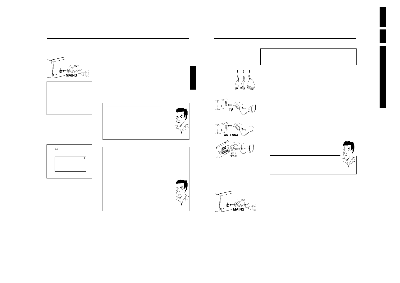
7 A message appears on the screen announcing that the transfer has
started. 'EASYLINK' appears on the display during transfer.
The TV set transfers all saved TV channels, in the same order, to the
DVD recorder.
This may take several minutes.
a'Time', 'Year', 'Month', 'Date' appears on the TV screen
Normally the date and time are taken from the data sent by the TV
channel stored on programme P01. If th aerial signal is too weak or there
is excessive interference, you should set the date and time manually:
1
Check if the time in 'Time' is correct.
2
If required, change the time with the number buttons 0..9 on your
remote control.
3
Select the next line with CH+ A or CH- B .
4
Check if the displayed settings for 'Year', 'Month' and 'Date' are
correct.
5
When all information is correct, save by pressing OK .
I can see more installation menus on my TV set
a
Not all the necessary data has been transferred. Please enter the settings
by hand as follows. For more information on the various functions see
'Initial installation' in 'Installing your DVD recorder'.
1
Select the desired audio language using CH- B or CH+ A and confirm
with OK .
2
Select the desired subtitle language with CH- B or CH+ A and
confirm with OK .
3
Select the desired screen format position using CH- B or CH+ A .
'4:3 letterbox' For a 4:3 TV set; cinema format (black bars above and
'4:3 panscan' For a 4:3 TV set; full height format with the sides cut
'16:9' For a 16:9 TV set
4
Confirm with OK .
5
Select the country of your residence with CH- B or CH+ A .
If your country does not appear, select 'Other'.
6
Confirm with OK .
below the picture)
off
Initial installation is now complete.
Problem
Problem
ENGLISH
Connecting with a scart cable without
'Easy Link'
Have the following cables ready:
an aerial cable (1, supplied), a mains cable (2, supplied), a scart cable (3).
1 Remove the aerial cable plug from your TV set. Insert it into the
ANTENNA IN socket at the back of the DVD recorder.
2 Insert one end of the supplied aerial cable into the TV OUT socket at
the back of the DVD recorder and the other end into the aerial input
socket at the back of the TV set.
3 Plug a scart cable into the scart socket EXT 1 TO TV-I/O at the
back of the DVD recorder and the scart socket for the DVD
recorder at the back of the TV set (see TV set operating instructions).
My TV set has several scart sockets. Which one should I use?
Select the scart socket that is suitable for both video output and for video
input.
My TV set shows me a selection menu for the scart socket
Select 'VCR' as tje source for this scart socket.
4 Switch on the TV set.
5 Insert one end of the supplied mains cable into the mains socket
4MAINS at the back of the DVD recorder and the other end into
the wall socket.
The most important features of the DVD recorder will appear in
scrolling text on the display. After the first installation is completed
this function will be switched off. How you switch on this function
again, read in the chapter 'User preferences' in the section 'standby'.
6 Switch on the DVD recorder using STANDBY/ON m .'IS TV ON?'
will appear on the display.
EN 12 DVDR70 & DVDR75/0x13.
Directions For Use
?
Connecting the DVD recorder
13
14
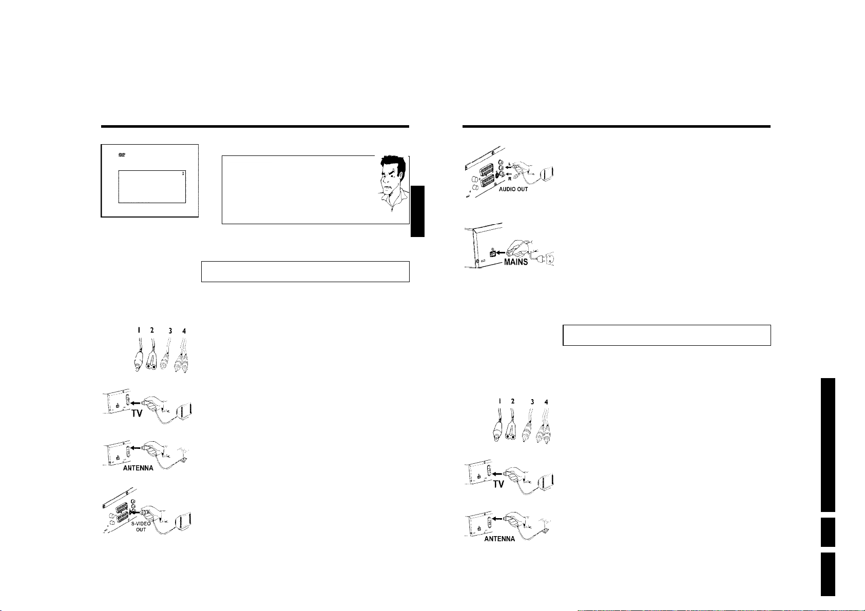
7 If the connection was properly made and your TV was automatically
switched to the programme number for the scart socket, e.g. 'EXT',
'0', 'AV', you will see the following picture:
Connecting the DVD recorder
Page 13
Menu Language
English
Español
Français
Italiano
Deutsch
Press OK to continue
Virgin mode
aMy screen is empty.
b Many TV sets are switched by the DVD recorder to the programme
number for the scart socket by way of a control signal sent through the
scart cable.
b If the TV set does not automatically switch to the scart socket programme
number, manually change to the corresponding programme number on your
TV set (see your TV's operating instructions).
b Check that the scart cable is connected from the TV set to the EXT 1
TO TV-I/O socket on the DVD recorder. The EXT 2 AUX-I/O socket is
intended only for additional devices.
Then, read the paragraph on 'Initial installation' in 'Installing your DVD recorder'.
Problem
Connecting with an SVideo(Y/C)cable
This connecting cable, also known as the SVHS cable, is used to transmit the brightness signal (Y
signal) and colour signal (C signal) separately. This mini DIN socket/plug is also called a Hosiden
socket/plug.
ENGLISH
4 Insert one end of the supplied audio (Cinch) cable into the red/white
Cinch socket OUT L AUDIO R at the back of the DVD recorder
and the other end into the audio input socket (usually red/white) on
the TV set (usually labelled 'Audio in' or 'AV in'. See TV operating
instructions).
5 Switch on the TV set. Switch the TV set over to the SVHS input
socket or select the relevant programme number. Please see your
TV's operating instructions for the programme number you need.
6 Insert one end of the supplied mains cable into the mains socket
4MAINS at the back of the DVD recorder and the other end into
the wall socket.
The most important features of the DVD recorder will appear in
scrolling text on the display. After the first installation is completed
this function will be switched off. How you switch on this function
again, read in the chapter 'User preferences' in the section 'standby'.
7 Switch on the DVD recorder using STANDBY/ON m . IS TV ON?'
will appear on the display.
Then, read the paragraph on 'Initial installation' in 'Installing your DVD recorder'.
Directions For Use
Connecting the DVD recorder
Have the following cables ready:
an aerial cable (1, supplied), a mains cable (2, supplied), an S-Video(SVHS) cable (3), an audio
cable (4, supplied, red/white plug).
1 Remove the aerial cable plug from your TV set. Insert it into the
ANTENNA IN socket at the back of the DVD recorder.
2 Insert one end of the supplied aerial cable into the TV OUT socket at
the back of the DVD recorder and the other end into the aerial input
socket at the back of the TV set.
3 Insert one end of an S-Video(SVHS) cable into the OUT S-VIDEO
(Y/C) socket at the back of the DVD recorder and the other end into
the S-Video (SVHS) input socket on the TV set (usually labelled
'S-Video in' or 'SVHS in'. See TV operating instructions).
15
16
Connecting with video(CVBS) cable
This cable, usually with yellow Cinch connectors, is used for transmitting the Composite Video
signal (FBAS, CVBS). In this method of transmission the colour signal and the brightness signal
are transmitted on the same cable. In certain circumstances, this can lead to problems with the
picturem, such as 'Moiré' patterns.
Have the following cables ready:
an aerial cable (1, supplied), a mains cable (2, supplied), a video (CVBS)cable (3, supplied, yellow
plug), an audio cable (4, supplied, red/white plug).
1 Remove the aerial cable plug from your TV set. Insert it into the
ANTENNA IN socket at the back of the DVD recorder.
2 Insert one end of the supplied aerial cable into the TV OUT socket at
the back of the DVD recorder and the other end into the aerial input
socket at the back of the TV set.
Connecting the DVD recorder
EN 13DVDR70 & DVDR75/0x1 3.
Page 14
EN 14 DVDR70 & DVDR75/0x13.
3 Insert one end of the supplied video (CVBS) cable into the yellow
Cinch socket OUT VIDEO (CVBS) at the back of the DVD
recorder and the other end into the video input socket (usually
yellow) on the TV set (usually labelled 'Video in' or 'AV in'. See TV
operating instructions).
4 Insert one end of the supplied audio (Cinch) cable into the red/white
Cinch socket OUT L AUDIO R at the back of the DVD recorder
and the other end into the audio input socket (usually red/white) on
the TV set (usually labelled 'Audio in' or 'AV in'. See TV operating
instructions).
5 Switch on the TV set. Switch the TV set over to the Video/Audio
input socket or select the relevant programme number. Please see
your TV's operating instructions for the programme number you need.
6 Insert one end of the supplied mains cable into the mains socket
4MAINS at the back of the DVD recorder and the other end into
the wall socket.
The most important features of the DVD recorder will appear in
scrolling text on the display. After the first installation is completed
this function will be switched off. How you switch on this function
again, read in the chapter 'User preferences' in the section 'standby'.
7 Switch on the DVD recorder using STANDBY/ON m .'IS TV ON?'
will appear on the display.
Then, read the paragraph on 'Initial installation' in 'Installing your DVD recorder'.
ENGLISH
C
Connecting additional devices
Connecting additional devices to the
second scart socket
You can connect additional devices such as decoders, satellite receivers, camcorders, etc. to the
EXT 2 AUX-I/O socket. When playback is started on this additional device the DVD recorder
automatically connects the EXT 2 AUX-I/O scart socket with the EXT 1 TO TV-I/O scart
socket. You will then see the picture from the additional device on your TV set, even if the
DVD recorder is switched off.
The TV/DVD button on the remote control allows you to switch between playback through the
EXT 2 AUX-I/O scart socket and playback from the DVD recorder.
Connecting additional video recorders
You can connect a video recorder to the EXT 2 AUX-I/O socket.
If you have an SVHS video recorder you can also use the OUT S-VIDEO (Y/C) socket and the
OUT L AUDIO R sockets.
Please note:
Most prerecorded video cassettes and DVDs are copy-protected. If you try to copy them you
will see the message 'COPY PROT' on the DVD recorder's display.
aWhen copying video cassettes the display on the DVD recorder
shows 'NO SIGNAL'
b Check that the cable is plugged in firmly.
b If a recording is made from a video recorder, change the tracking on the
video recorder.
b The DVD recorder may not be able to recognise the video input signal if
this signal is poor or does not comply with relevant standards.
When I copy DVD video discs or prerecorded video cassettes the
a
picture is fuzzy and the brightness varies
b This happens if you try to copy DVDs or video cassettes that have been
copy-protected. Even though the picture on the TV is fine the recording on
a DVD+R(W) is faulty. This interference is unavoidable with copy-protected
DVDs or video cassettes.
Directions For Use
Problem
Connecting the DVD recorder
17
18
Connecting additional devices
Page 15
Connect camcorder to the front sockets
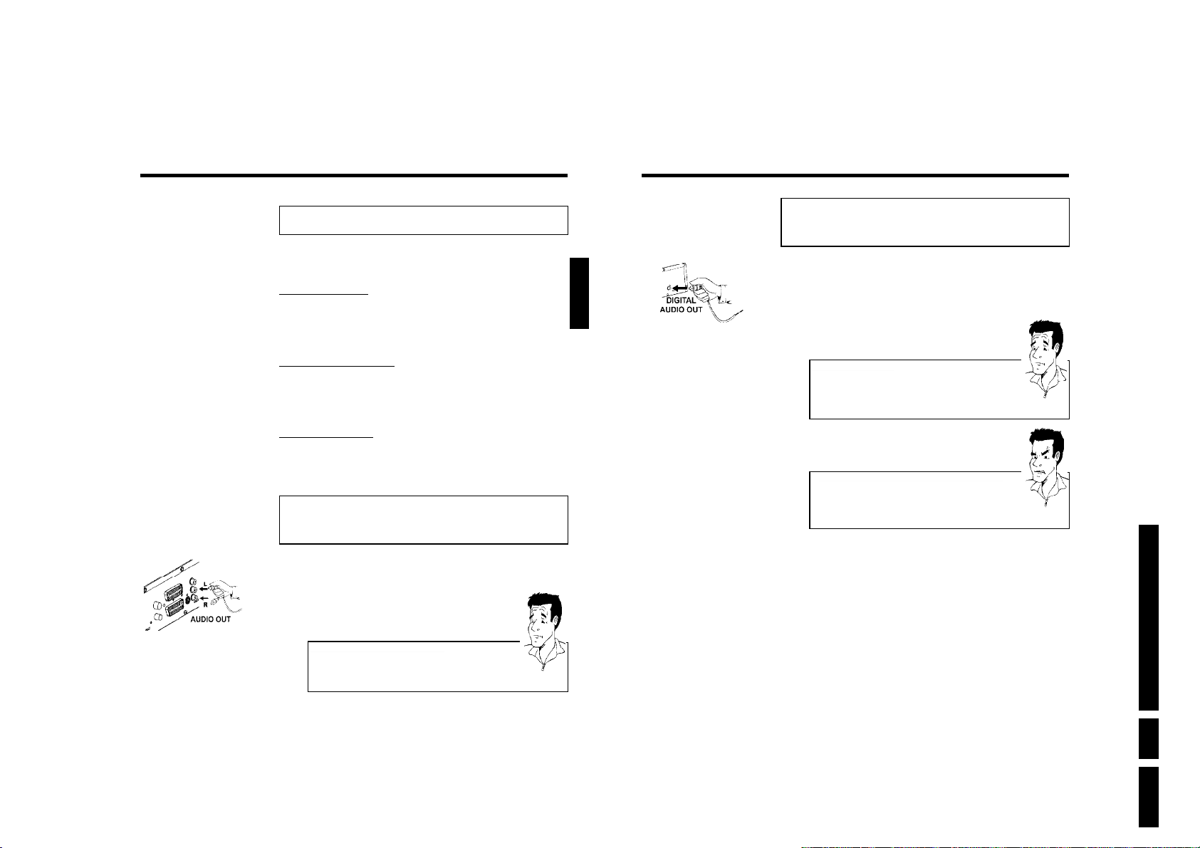
To copy camcorder recordings, you can use the front sockets. These sockets are located behind
the flap on the left hand side.
Best picture quality
If you have a DV or Digital 8 camcorder, connect the DV IN input of the DVD recorder to the
appropriate DV output on the camcorder.
When films are transferred the original recording date and time are stored as DVD subtitles.
On playback, this data can be displayed on the TV screen by using the '
' function (Subtitle).
E
Very good picture quality
If you have a Hi8 or S-VHS(C) camcorder, connect the S-VIDEO input of the DVD recorder to
the appropriate S-VHS output on the camcorder.
You must also connect the audio input left AUDIO right on the DVD recorder to the audio
output on the camcorder.
Good picture quality
If you have a camcorder that only has a single video output (Composite Video, CVBS), connect
the VIDEO input on the DVD recorder to the appropriate output on the camcorder.
You must also connect the audio input left AUDIO right on the DVD recorder to the audio
output on the camcorder.
Connecting audio devices to the analogue
audio sockets
Two audio output sockets OUT L AUDIO R are located on the back of the DVD recorder
(audio signal output left/right)
These can be used to connect the following:
•) a receiver with Dolby Surround Pro Logic
•) a receiver with twochannel analogue stereo
ENGLISH
Connecting audio devices to the digital
audio socket
At the back of the DVD recorder there is a digital audio output socket DIGITAL AUDIO
OUT for an coaxial cable.
These can be used to connect the following:
•) an A/V receiver or an A/V amplifier with a digital multichannel sound decoder
•) a receiver with twochannel digital stereo (PCM)
Digital multichannel sound
Digital multi-channel sound offers the best possible sound quality. You will
need a multi-channel A/V receiver or amplifier that supports at least one of
the audio formats of the DVD recorder (MPEG2, Dolby Digital and DTS).
Consult the operating instructions for your receiver to find out which audio
formats it supports.
aAll I can hear from my loudspeakers is a loud distorted noise
b The receiver is not compatible with the digital audio format of the DVD
recorder. The audio format of the DVD disc is displayed in the status
window when you switch to anoter language. Playback in six-channel digital
surround sound is only possible if the receiver has a digital multi-channel
sound decoder.
?
Problem
Directions For Use
Connecting additional devices
Can I use the 'Phono' input on my amplifier?
This socket (input) on the amplifier is designed only for record players
without preamplifiers. Do not use this input for connecting the DVD
recorder.
The DVD recorder or the amplifier may be damaged as a result.
?
EN 15DVDR70 & DVDR75/0x1 3.
19
20
Connecting additional devices
Page 16
EN 16 DVDR70 & DVDR75/0x13.
D
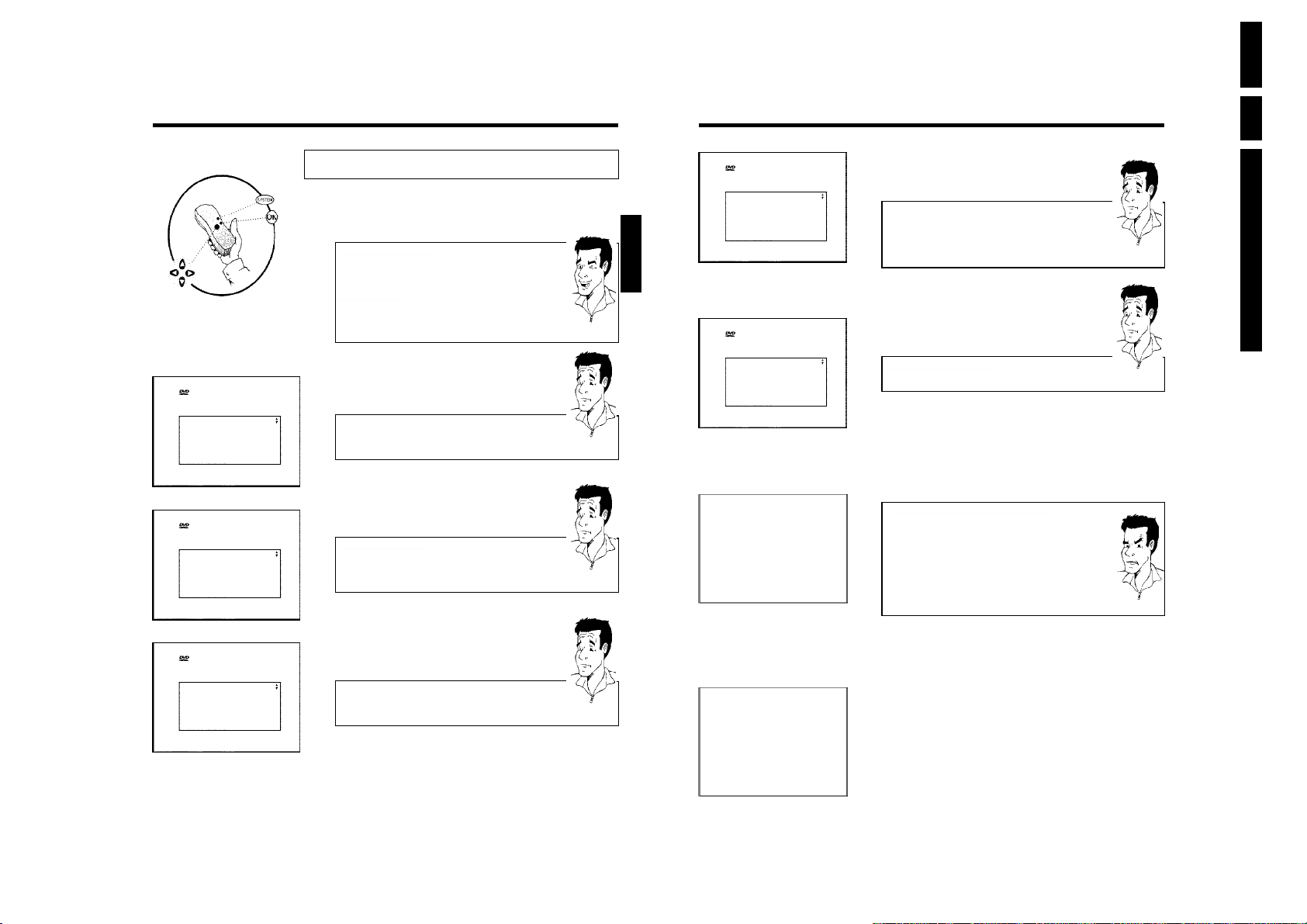
Menu Language
English
Español
Français
Italiano
Deutsch
Press OK to continue
Audio Language
English
Español
Français
English
Italiano
Press OK to continue
Subtitle Language
English
Español
Français
English
Italiano
Press OK to continue
Installing your DVD recorder
Initial installation
After successfully connecting your DVD recorder to the TV set and other additional devices as
described in the previous chapters, this chapter will show you how to start the initial installation.
The DVD recorder automatically seeks out and stores all available TV channels.
Connecting additional devices
If you have connected additional devices such as a satellite receiver to the
aerial cable, switch them on. The automatic channel search will recognise it
and save it.
No aerial connected
Even if you only want to use the DVD recorder to play back or have only
connected a satellite receiver, you must still complete the initial installation.
This is necessary so that the basic settings are stored correctly. Once initial
installation is complete you can use the DVD recorder as normal.
Virgin mode
Virgin mode
Virgin mode
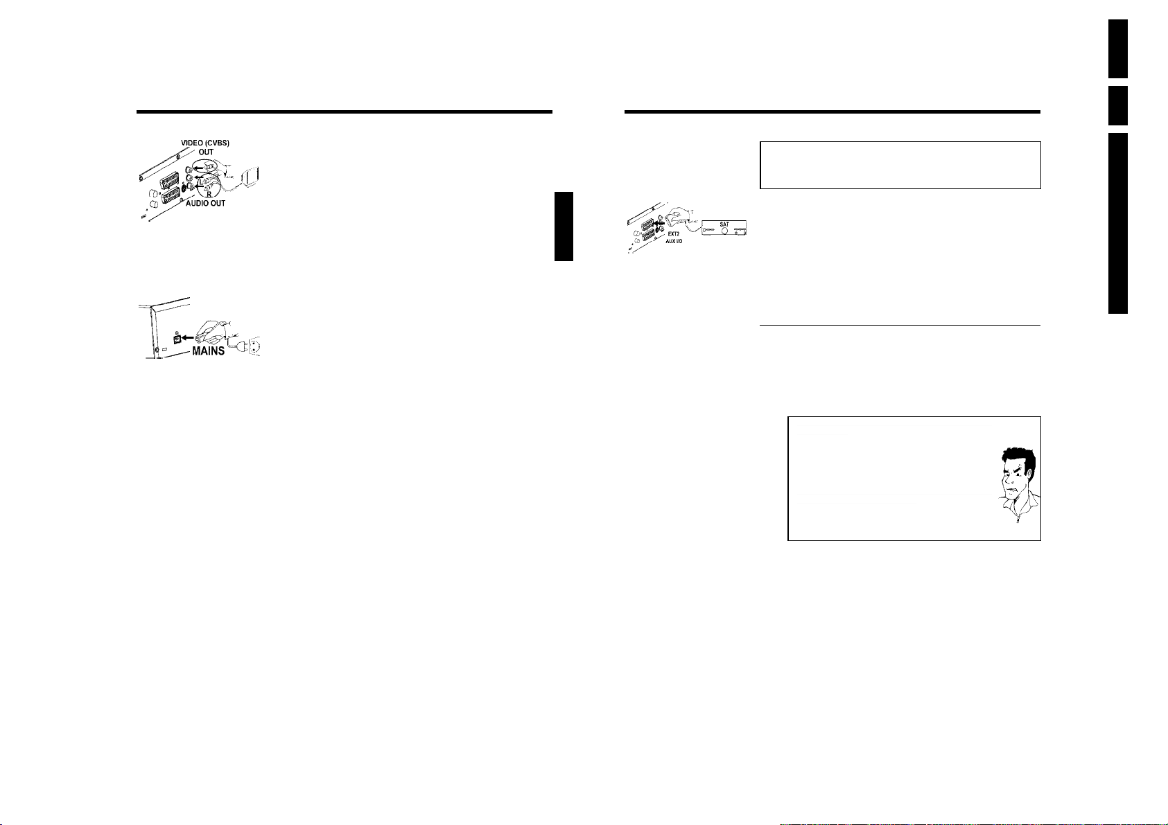
1 Select the desired language for the on-screen menu by pressing
CH- B or CH+ A .
What is an onscreen menu?
The multi-language on-screen menu takes the mystery out of using your new
DVD recorder. All settings and/or functions are displayed on your TV screen
in the relevant language.
2 Confirm with OK .
3 Select the desired audio language using CH- B or CH+ A .
What is an audio language?
The DVD will play the sound in the language you select, provided this
language is available on the disc. If it is not available on the disc the fist
language on the DVD will be used instead. The DVD Video Disc menu, if
available, will also be displayed in the language you select.
4 Confirm with OK .
5 Select the desired language for the subtitles by pressing CH- B or
CH+ A .
What is the subtitle language?
The subtitles will be displayed in the language you select, provided this
language is available on the disc. If it is not available on the disc the fist
language on the DVD will be used instead.
6 Confirm with OK .
Tip
Virgin mode
TV Shape
4:3 letterbox
4:3 panscan
16:9
Press OK to continue
ENGLISH
Virgin mode
Country
Austria
Belgium
Denmark
Finland
France
Press OK to continue
?
Installation
Autom. search
Searching for TV channels
00 Channels found
?
?
Please wait
Autom. search
Autom. search complete
00 Channels found
Time 20:01
Year 2003
Month 01
Date 01
To continue
Press OK
7 Select the desired screen format position using CH- B or CH+ A .
These settings will only be used if you insert a DVD that contains this
information.
Which screen formats can I select?
'4:3 letterbox' for a 'wide-screen' (cinema format) picture with black bars at
'4:3 panscan' for a full-height picture with the sides trimmed.
'16:9' for a wide-screen TV set (screen edge ratio 16:9)
8 Confirm with OK .
9 Select the country of your residence with CH- B or CH+ A .
If your country does not appear, select 'Other'.
Why do I have to select a country?
To call up the specific settings for the respective country, you must first install
the country.
0 Confirm with OK .
A After you connect the aerial (or cable TV, satellite receiver, etc.) to
the DVD recorder, press OK .
The automatic TV channel search starts. 'WAIT' will appear on the
display.
The DVD recorder cannot find any TV stations
a
b Select channel 1 on the TV set. Can you see the stored TV channel on the
TV set?
If not, check the cable connection from the aerial (aerial socket) to the
DVD recorder and to the TV set.
b Please have patience.
The DVD recorder searches the entire frequency range in order to find
and save the largest possible number of TV channels.
b If you have not connected an aerial, go through all the basic settings right
to the end and then, if you wish, start the automatic search (see 'Automatic
TV station search').
B When the automatic TV channel search is complete, 'Autom. search
complete' will appear on the TV screen.
'Time', 'Year', 'Month', 'Date' will then appear on the TV screen.
C Check if the time in 'Time' is correct.
À If required, change the time with the number buttons 0..9 on your
remote control.
Á Select the next line with CH+ A or CH- B .
the top and bottom.
?
Directions For Use
?
Problem
Installing your DVD recorder
21
22
Installing your DVD recorder
Page 17
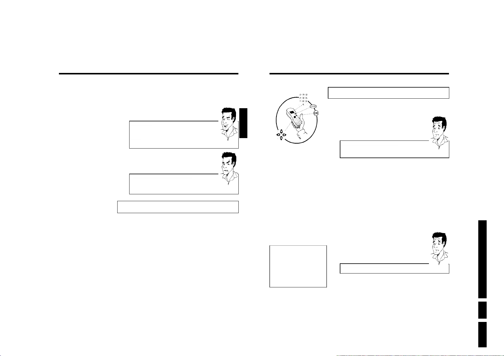
 Check if the displayed settings for 'Year', 'Month' and 'Date' are
correct.
à When all information is correct, save by pressing OK .
The initial installation is now complete.
Satellite receiver
If you are connecting a satellite receiver, please read the section on 'Using a
satellite receiver'.
Decoder
If you are connecting a decoder, you must install it as described in the next
section.
Tip
ENGLISH
Allocating a decoder
Some TV channels send coded TV signals that can only be viewed properly with a purchased or
rented decoder. You can connect such a decoder (descrambler) to your DVD recorder. The
following function automatically activates the connected decoder for the TV channel you want to
watch.
How do I allocate the decoder for Easy Link?
If your TC=V set supports 'Easy Link' the decoder must be assigned to the
relevant TV channel on the TV set (see the operating instructions for your TV
set). Settings cannot then be made in this menu.
?
aSound may be distorted on some TV channels.
b If the sound is distorted on any of the stored TV channels or if there is no
sound at all, the wrong TV system may have been stored for the TV
channel. Read 'Manual TV channel search' for information on how to
change the TV system.
Problem
Using a satellite receiver
TV channels from a satellite receiver (connected to scart socket EXT 2 AUX-I/O ) are received
on the DVD recorder on programme number 'EXT2'
If necessary, use the MONITOR button to switch to the internal tuner.
Select programme number 'EXT1' with 0 on the remote control and then select programme
number 'EXT2' with CH- B .
You should select the TV channels to be received by the satellite receiver directly on the
receiver itself.
Installation
Manual search
Channel/freq. CH
Entry/search 01
Programme number 01
TV channel name BBC1
Decoder Off
TV system PAL-BG
NICAM On
Fine tuning 0
1 Switch on the TV set. If required, select the programme number for
the DVD recorder.
2 Switch on the DVD recorder using STANDBY/ON m .
3 Use the CH+ A and CH- B buttons or the number buttons
0..9 on the remote control to select the TV channel for which you
want to use the decoder. If necessary, use the MONITOR button to
switch to the internal tuner.
4 Press the SYSTEM-MENU button on the remote control. The menu
bar appears.
5 Select '
6 Select 'Installation' using CH- B or CH+ A and confirm with C .
7 Select 'Manual search' using CH- B or CH+ A and confirm with
8 Select 'Decoder' using CH- B or CH+ A .
9 Select 'On' with D or C .
0 Confirm with OK .
To store
Press OK
A To end, press SYSTEM-MENU .
Your decoder has now been allocated to this TV channel.
' symbol with D or C .
A
C .
How do I switch the decoder off again?
Use C to select 'Off'inthe'Decoder' line on the screen (Decoder off).
Directions For Use
?
EN 17DVDR70 & DVDR75/0x1 3.
Installing your DVD recorder
23
24
Installing your DVD recorder
Page 18
EN 18 DVDR70 & DVDR75/0x13.
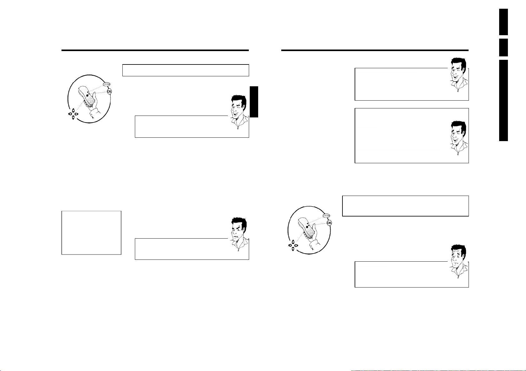
Installation
Manual search
Channel/freq. CH
Entry/search 01
Programme number 01
TV channel name BBC1
Decoder Off
TV system PAL-BG
NICAM On
Fine tuning 0
Manual TV channel search
In some cases, not all of the available TV channels may have been found and stored during initial
installation. In this case, you will need to search for and store the missing or coded TV channels
manually.
Manual search with EasyLink
With 'Easy Link', the DVD recorder will automatically download the TV
channels stored on the TV set. This is why some lines have no function. To
store new TV channels, they must first be stored on the TV set. The
information will then be transferred to the DVD recorder automatically.
1 Switch on the TV set. If required, select the programme number for
the DVD recorder.
2 Switch on the DVD recorder using STANDBY/ON m .
3 Press SYSTEM-MENU on the remote control. The menu bar
appears.
To store
Press OK
4 Select '
5 Select 'Installation' using CH- B or CH+ A and confirm with C .
6 Select 'Manual search' using CH- B or CH+ A and confirm with
7 In 'Channel/freq.', select the desired display using C .
8 In 'Entry/search', enter the frequency or channel of the TV station
9 Using D or C in 'Programme number', select the programme
' symbol with D or C .
A
C .
'Freq.'(Frequency), 'CH'(Channel), 'S-CH'(Special/hyperband channel)
using the number buttons 0..9 .
aI don't know the channel for my TV station
b In this case, press C to start the automatic search. A changing channel
number/frequency number will appear on the TV screen.
Continue the automatic search until you have found the TV channel you
are looking for.
number you want to use for the TV channel, e.g. '01'.
Tip
Problem
ENGLISH
How can I change the symbol of a TV channel?
1
In 'TV channel name', press C .
2
Select the desired symbol position using D or C .
3
Change the symbol at the symbol position with CH- B or CH+ A .
4
Select the next symbol position in the same way.
5
Keep pressing C until the cursor disappears.
How can I change the TV system of the TV channel?
In 'TV system', use D or C to select the TV system that produces the
least distortion of picture and sound.
What is NICAM?
NICAM is a digital sound transmission system. Using NICAM, you can
transmit either 1 stereo channel or 2 separate mono channels. However, if
reception is poor and the sound distorted you can turn off NICAM.
In 'NICAM', select 'Off' using D or C .
How can I improve the automatic process for storing channels?
To change the automatic process for storing channels (fine tuning), select
'Fine tuning'.
Using D or C you can try to fine-tune the TV channelmanually.
0 Press OK to store the TV channel.
A To search for other TV channels, begin again at
B To end, press SYSTEM-MENU .
8
.
Tip
Tip
Sorting TV channels automatically
(Follow TV)
When the automatic channel search function is activated, the TV channels are stored in a specific
order. This may differ from the order in which the TV channels appear on your TV set.
This function changes the order of the TV channels stored in your DVD recorder to match the
order on the TV set.
This only works if the DVD recorder ( EXT 1 TO TV-I/O socket) and the TV set are
connected with a scart cable.
What does EasyLink do?
If your TV set supports 'Easylink,..', TV channels will be stored during initial
installation in the same order as they appear on the TV set. To store the TV
channels in a different order, you'll need to change the order on the TV set.
When you start the Follow TV function the information is transferred again
from the TV set.
?
Directions For Use
Installing your DVD recorder
25
26
1 Switch on the TV set. If required, select the programme number for
the DVD recorder.
Installing your DVD recorder
Page 19
2 Switch on the DVD recorder using STANDBY/ON m .
3 Press the SYSTEM-MENU button on the remote control. The menu
bar appears.
4 Select '
5 Select 'Installation' using CH- B or CH+ A and confirm with C .
6 Select line 'Follow TV' with CH- B or CH+ A . and confirm with
7 Confirm the message on the screen with OK .'TV 01' will appear in
' symbol with D or C .
A
the C button.
the DVD recorder display.
ENGLISH
Automatic TV channel search
During installation, all available TV channels are searched for and stored. If the channel
assignments of your cable or satellite TV provider change or if you are reinstalling the DVD
recorder, e.g. after moving house, you can start this procedure again. This will replace the stored
TV channels with the new ones.
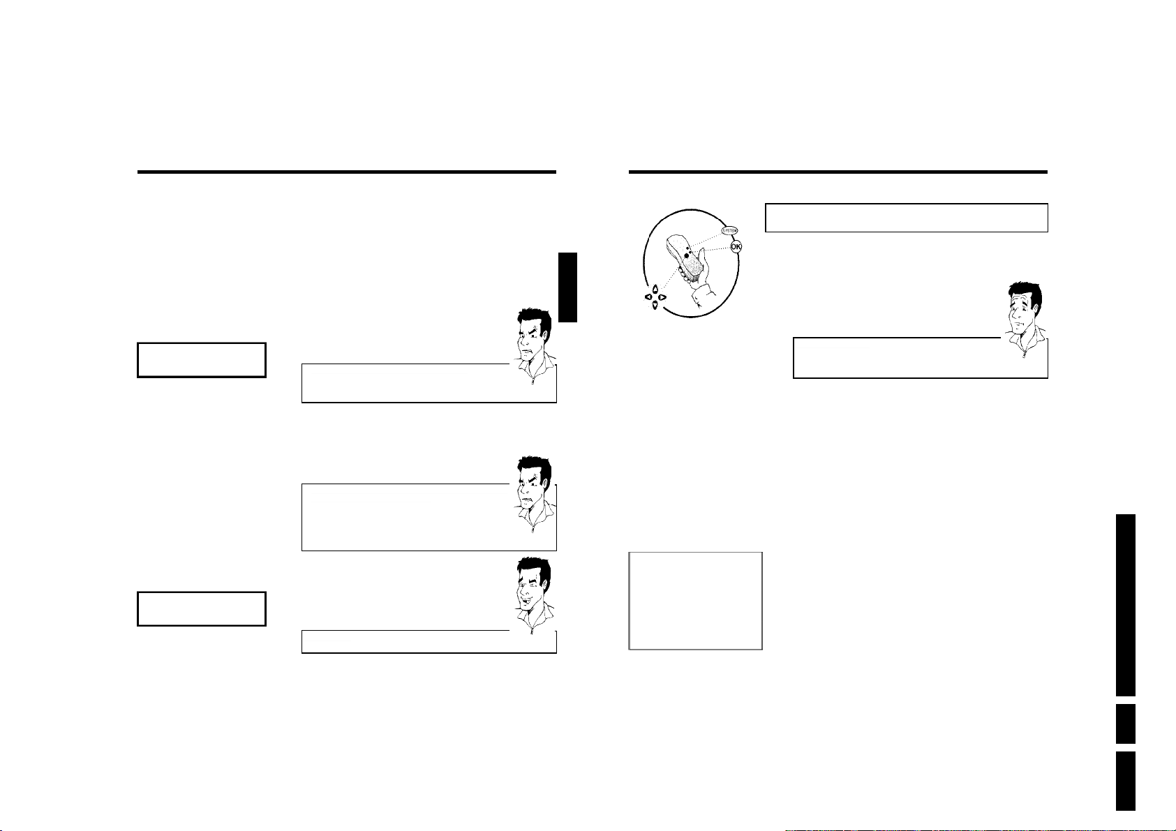
TV 01
TV 02
8 Select programme number '1' on the TV set.
aI cannot switch my TV set to programme number '1'
b If you have connected additional devices to the EXT 2 AUX-I/O socket,
please disconnect these devices. Other connected devices may have
switched the TV set to the programme number of the scart socket.
9 Confirm with OK on the DVD recorder remote control.
'WAIT' will appear in the display. The DVD recorder compares the TV
channels on the TV set and the DVD recorder.
If the DVD recorder finds the same TV channel as on the TV set it
stores it at 'P01'.
a'NOTV' will appear in the display. The DVD recorder is not
receiving a video signal from the TV set.
b Chech the connectors at both ends of the scart cable.
b Check your TV's operating instructions to see which scart socket is used
for video signals.
b If the problem persists, you won't be able to use this feature.
Please read 'Adding and clearing TV channels manually'.
0 Wait until for example 'TV 02' appears in the display.
A Select the next programme number on the TV set, e.g. '2'.
B Confirm with OK on the DVD recorder remote control.
Deleting sorting
You can delete incorrect TV channel sorting by pressing D .
C Repeat steps0toBuntil you have assigned all the TV channels.
À To end, press SYSTEM-MENU .
Problem
Problem
Tip
Installation
Autom. search
Searching for TV channels
00 Channels found
Please wait
What does Easy Link do?
With Easylink, you can search for and store TV channels only on the TV set.
These settings are accepted by the DVD recorder. Use this function to start
the transfer of TV channels from the TV set.
1 Switch on the TV set. If required, select the programme number for
the DVD recorder.
2 Switch on the DVD recorder using STANDBY/ON m .
3 Press SYSTEM-MENU on the remote control. The menu bar
appears.
4 Select '
5 Select 'Installation' using CH- B or CH+ A and confirm with C .
6 Select 'Autom. search' using CH- B or CH+ A .
7 Press C .
8 The automatic TV channel search starts. This allows the DVD
9 When all the TV channels have been found, 'Autom. search
0 To end, press SYSTEM-MENU .
You can read about how to search for a TV channel manually in 'Manual TV channel search'.
' symbol with D or C .
A
recorder to save all available TV channels. This procedure may take
several minutes.
complete' will appear on the TV screen.
?
Directions For Use
Installing your DVD recorder
27
28
EN 19DVDR70 & DVDR75/0x1 3.
Installing your DVD recorder
Page 20
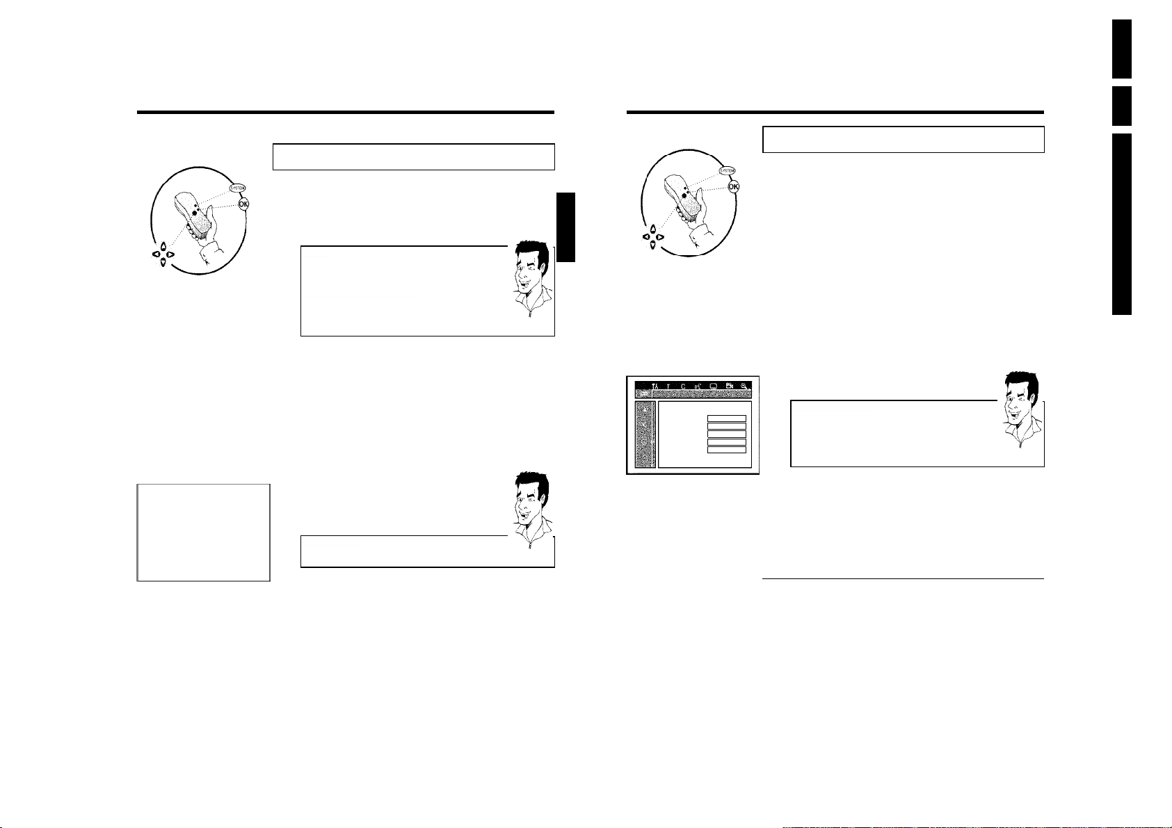
Installation
Sort TV channels
...
• P01 BBC1
P02 BBC2
P03 ITV
P04
P05
P06
...
To sort
Press ›
To exit press
SYSTEM MENU
Adding and clearing TV channels manually
After you have performed the automatic channel search you may not agree with the sequence in
which the individual TV channels have been allocated to the programme positions (programme
numbers). You can use this function to rearrange the TV channels already stored or to delete
TV channels you don't want or those with poor reception.
EasyLink
With Easylink, you can search for and store TV channels only on the TV set.
These settings are then accepted by the DVD recorder.
That is why you cannot select this function manually.
The teletext clock resets automatically
If you store a TV channel which transmits TXT/PDC on programme number
'P01', the date and time will automatically be transmitted and constantly
updated. As a result, the changes from summer time to winter time and back
again will be made automatically.
1 Switch on the TV set. If required, select the programme number for
the DVD recorder.
2 Switch on the DVD recorder. Press the SYSTEM-MENU button on
the remote control. The menu bar appears.
3 Select '
4 Select 'Installation' using CH- B or CH+ A and confirm with C .
5 Select 'Sort TV channels' using CH- B or CH+ A and confirm
6 Using CH- B or CH+ A select the TV channel that you want to
7 Confirm with C .
8 Using CH- B or CH+ A , shift the TV channel to the desired
9 Repeat steps
0 To store, press OK .
A To end, press SYSTEM-MENU .
' symbol with D or C .
A
with C .
delete or whose order you want to change.
Deleting TV channels
Unwanted channels or those with poor reception can be deleted using
CLEAR . Proceed at step 6 .
position and press the D button. The DVD recorder will insert the
TV channel.
6to8
channels you want.
until you have resorted/deleted all the TV
Tip
Tip
ENGLISH
Audio Language English
Recording audio Language 1
Subtitle English
Menu English
Country Other
Setting the language/country
You can select the country and, for DVD playback, the language for the subtitles and the audio
language. Please note that with some DVDs the audio language and/or subtitle language can be
changed only via the DVD menu.
For bilingual shows you can also select the sound channel of the TV station for recording.
You also have the option of setting one of the displayed languages for the on-screen menu
(OSD). However, the DVD recorder display will only display English text regardless of this
setting.
1 Switch on the TV set. If required, select the programme number for
the DVD recorder.
2 Switch on the DVD recorder using STANDBY/ON m .
3 Press SYSTEM-MENU on the remote control. The menu bar
appears.
4 Select '
5 Select line 'Language' with CH- B or CH+ A . and confirm with
6 Select the appropriate line and confirm with C .
Language
7 Select the appropriate setting using CH- B or CH+ A and confirm
8 To end, press SYSTEM-MENU .
' symbol with D or C .
A
the C button.
Which settings can I choose?
'Audio Language' : Playback language (audio language)
'Recording audio' : Type of audio recording 'Language 1'or'Language
2'
'Subtitle' : Subtitle language
'Menu': Language of the OSD menu
'Country' : Location (country)
with OK .
Switching over audio recording
(2channel sound)
Some TV programmes transmit an extra audio signal in stereo in addition to the normal audio
signal (2-channel sound). In most cases this means that an additional language is available. If a TV
programme is available in, say, English and German, German may be available as the second
language.
To record TV programmes in stereo or 2-channel sound you can select Stereo or the language
you want as the default setting. This setting does not become active until the sound of a TV
programme is transmitted in 2-channel sound.
When you play back the recording you can play back the sound only in the language you used
for the recording.
EN 20 DVDR70 & DVDR75/0x13.
Directions For Use
Tip
Installing your DVD recorder
29
30
Installing your DVD recorder
Page 21
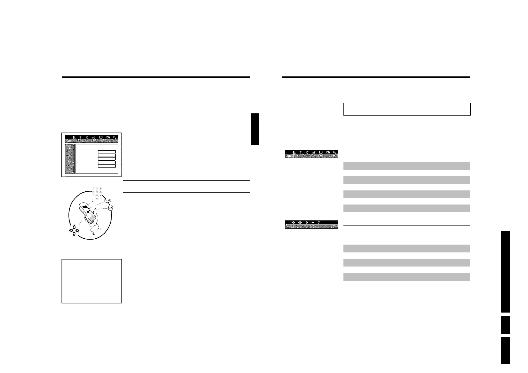
E
Onscreen information
Audio Language English
Recording audio Language 1
Subtitle English
Menu English
Country Other
Installation
Time/Date
Time 20:00
Year 2003
Month 01
Date 01
To exit press
SYSTEM MENU
1 Switch on the TV set. If required, select the programme number for
the DVD recorder.
2 Switch on the DVD recorder using STANDBY/ON m .
3 Press SYSTEM-MENU on the remote control. The menu bar
appears.
4 Select '
5 Select line 'Language' with CH- B or CH+ A . and confirm with
6 Select line 'Recording audio' and confirm with C .
Language
7 Select 'Language 1'or'Language 2' with CH- B or CH+ A and
8 To end, press SYSTEM-MENU .
' symbol with D or C .
A
the C button.
confirm with OK .
Setting the time and date
If the display shows an incorrect time or '--:--', the time and date must be reset manually.
If a TV channel which transmits TXT/PDC (teletext/PDC) is stored under programme number
'P01', the time and date will automatically be taken from the TXT/PDC information.
1 Press SYSTEM-MENU on the remote control. The menu bar
appears.
2 Select '
3 Select 'Installation' using CH- B or CH+ A and confirm with C .
4 Select 'Time/Date' using CH- B or CH+ A and confirm with C .
5 Check if the time in 'Time' is correct. If required, change the time
6 Check 'Year', 'Month' and 'Date' in the same way. To move between
7 Check the displayed settings and confirm with OK .
8 To end, press SYSTEM-MENU .
' symbol with D or C .
A
with the number buttons 0..9 on your remote control.
the fields, use CH- B or CH+ A .
'Stored' will appear briefly on the screen.
ENGLISH
You can check or change many of the functions and settings of your DVD recorder via the
system menu bar. The menu bar cannot be displayed during recording.
Symbols in the menu bar
Press SYSTEM-MENU to open and close the menu bar (main menu). Use D and C to select
the relevant function. Use CH- B to confirm the function and go either to another menu or
execute the function directly.
Some functions may not be available, depending on the disc inserted.
Menu bar 1
A
B
C
D
E
F
G
User preferences
Title/track
Chapter/index
Audio language
Subtitle language
Camera angle
Zoom
Menu bar 2
While menu bar 1 is being displayed you can go to menu bar 2 by pressing C again.
H
I
J
K
L
Sound
Frame advance
Slow motion
Fast forward
Search by time
Directions For Use
Installing your DVD recorder
31
32
EN 21DVDR70 & DVDR75/0x1 3.
On-screen information
Page 22
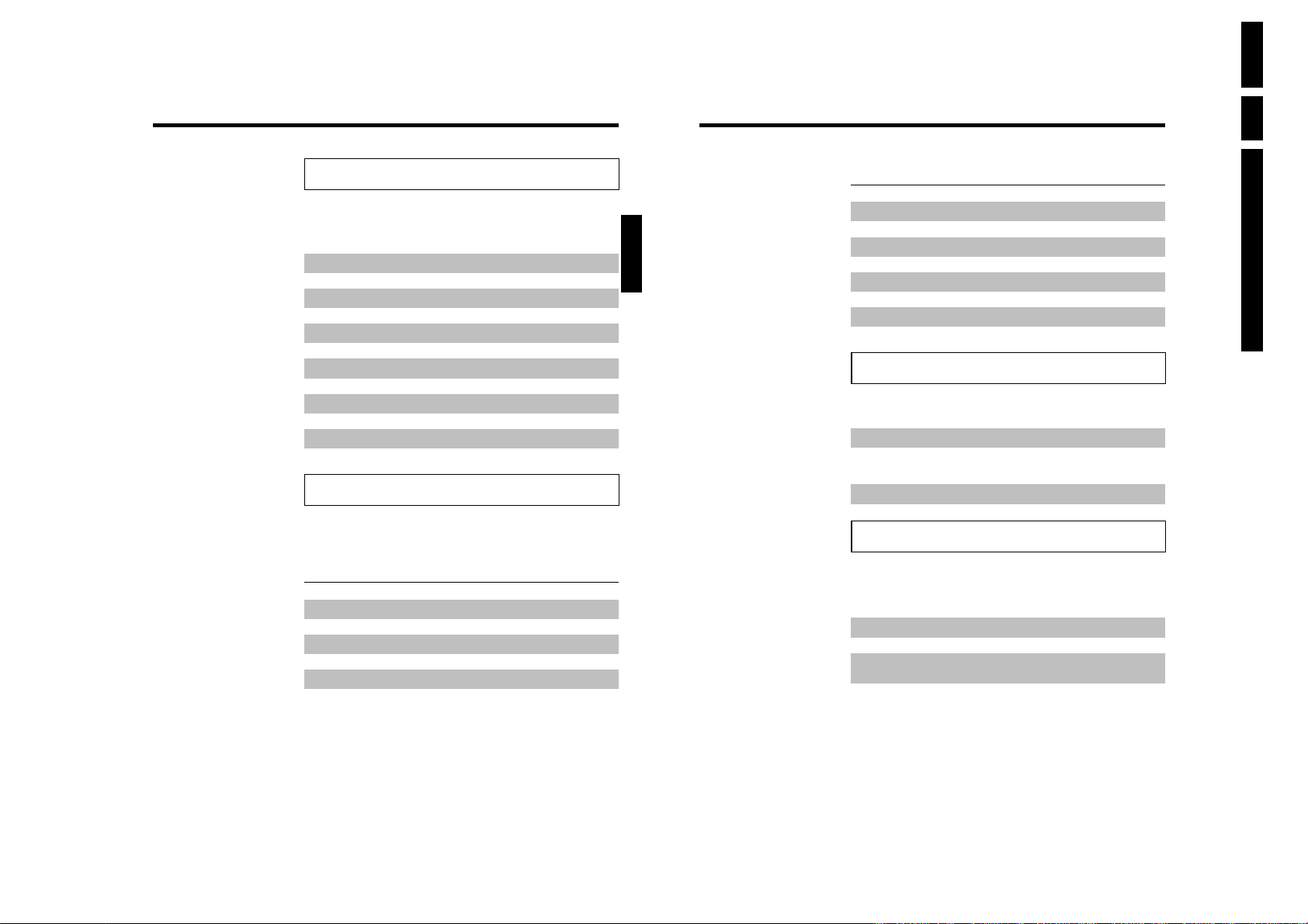
EN 22 DVDR70 & DVDR75/0x13.
Field for temporary messages
The top left corner of the menu line contains a field for temporary messages relating to the
various operating modes. This information appears briefly on the screen when certain disc
functions have been activated:
Shuffle
Scan
Repeat entire disc
Repeat title
Repeat track
Repeat chapter
Repeat from A to the end
Repeat from A to B
Camera angle
Child lock enabled
Resume playback
Illegal action
Status field
The status field shows the current operating mode (status) of the DVD recorder and the type of
disc inserted. This display can be disabled.
Disc type symbols
M
W
N
O
P
Q
DVD+RW
DVD+R
DVDVideo
VideoCD
No disc
Error
ENGLISH
Operating mode symbols
R
S
T
U
V
X
Y
Z
Recording
Stop
Playback
PlaybackPause
RecordPause
Search forwards (8x speed)
Search backwards (8x speed)
Slow motion
Tuner information box
This field is located in the bottom left-hand corner of the screen. The aerial signal, the TV
channel and the TV channel name for the selected programme are displayed.
a
b
c
Current channel/selected input socket
No signal
The TV channel is not available/the additional device is not connected or
it is switched off
Copyprotected signal
Timer information box
This box appears above the tuner information box. When a timer recording is set, it shows the
timer icon and the start time or date of the first programme to be recorded.
If no timer recording is scheduled, the current time is displayed.
This box disappears during playback of a disc or after a recording starts.
f
g
h
Timer starts on the day shown
OTR recording runs until the stop time displayed
Current time
No timer event programmed
Directions For Use
On-screen information
33
34
On-screen information
Page 23
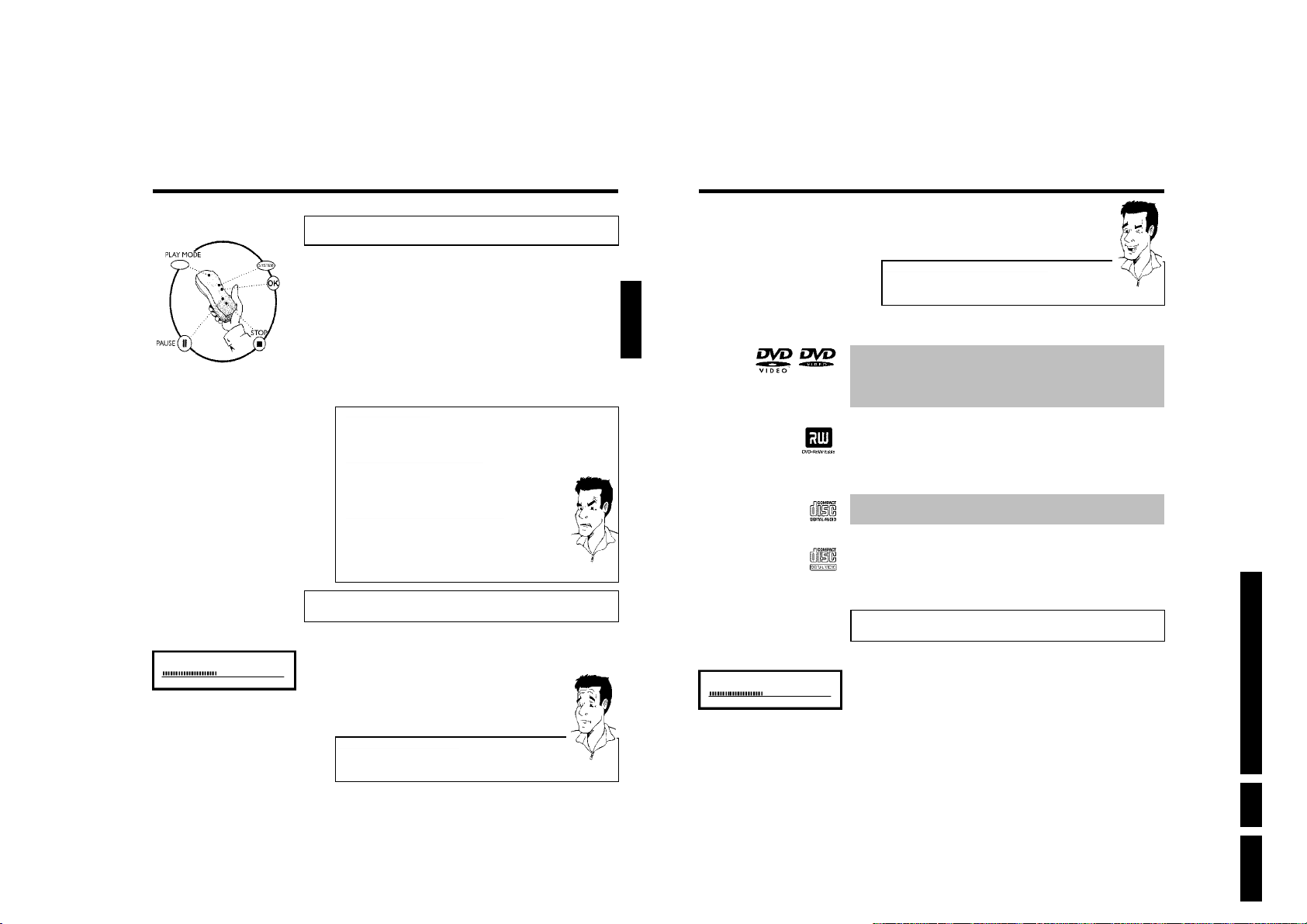
F
playback
General notes on playback
OPENING P01
With this DVD recorder you can play back the following systems:
•) DVD Video
•) (Super)Video CD Disc
•) DVD+RW Disc
•) DVD+R Disc
•) DVD-RW (video mode, finalised)
•) DVD-R
•) CD-R
•) CD-RW
•) Audio CD
•) MP3 CD
You can operate the video recorder using the remote control or the buttons on the front of the
DVD recorder.
aThe display will read 'PIN'
b The child lock has been activated for the inserted disc. Read the sections
on 'Child lock' and 'Releasing a disc' in the chapter on 'Access control
(child lock).
The menu on the screen is showing an 'X'
a
b Some DVD discs can be manufactured so that certain steps are required
before the disc can be played, or so that only limited operation is possible
during playback. When an 'X' appears on the screen the selected feature is
not possible.
The screen is showing regional code information
a
b Since DVD films are not normally released in all parts of the world at the
same time, all DVD players have a specific regional code. Discs can be given
a regional code. If the regional codes differ between the player and the
disc, playback is not possible.
b The regional code is shown on the label on the back of the machine.
b The regional code does not apply to recordable DVD discs.
Problem
Inserting a disc
1 Press the OPEN/CLOSE J button on the front. The disc tray will
open. While the disc tray is opening, 'OPENING' and then 'TRAY OPEN'
when the tray is fully open.
2 Carefully place the disc in the tray with the label facing up and press
PLAY G or OPEN/CLOSE J .'CLOSING' and then 'READING' will
appear in the display. The information on the disc will be read.
How do I insert a doublesided DVD?
Double-sided discs do not have labelling over the whole surface. The labelling
for each side is in the centre of the disc. To play a side its label must be
facing up.
?
ENGLISH
C01 2:04
Opening/closing the tray using the remote control
You can open and close the disc tray using the remote control.
Press and hold the STOP h button on the remote control until the dialog
box shows 'OPENING'or 'CLOSING'.
3 Playback starts automatically.
A menu may appear when a DVD is played back. If the titles and chapters are numbered, press a
number button on the remote control. You can also use the D , C , CH+ A ,
CH- B buttons or number buttons 0..9 to select a menu item and confirm with OK .
You can also access the menu using DISC-MENU on the remote control.
For further information see 'Playing a DVD video disc'.
When a DVD+RW is played back the index overview appears. Using CH- B , CH+ A , N ,
O select the title you want to play back.
Confirm with OK .
For further information see 'Playing back a DVD+RW/+R Disc'.
If playback does not start automatically, press PLAY G .
For further information see ' Playing an audio CD'.
If the 'h' symbol appears in the display, start playback by pressing PLAY G .
If a menu appears on the screen, use the remote control buttons indicated on the screen to select
the menu option you want (PREV= N , NEXT= O ) or with the number buttons 0..9 .
For further information see ' Playing a (Super) Video CD'.
Tip
Playing a DVD video disc
1 If playback does not start automatically, press PLAY G .
This will appear on the display:
title, chapter, elapsed time.
2 To stop playback, press STOP h on the remote control or h on
the DVD recorder.
3 To eject the disc, press OPEN/CLOSE J on the front of the DVD
recorder.
Directions For Use
playback
35
36
EN 23DVDR70 & DVDR75/0x1 3.
playback
Page 24
EN 24 DVDR70 & DVDR75/0x13.
C01 ANNA P01
Playing a DVD+RW/ +R disc
1 If the disc is write-protected or a finalised DVD+R disc, playback
starts automatically.
2 If playback does not start automatically, use the CH- B or
CH+ A button to select the title you want to play on the index
screen.
You can also use the N or O button on the front.
3 Press the PLAY G button.
This will appear on the display:
title number, recording quality.
aI can see the message 'EMPTYDISC'
b The disc does not contain any recordings.
4 To stop playback, press STOP h on the remote control or h on
the DVD recorder.
5 To eject the disc, press OPEN/CLOSE J on the front of the DVD
recorder.
What should I note when playing back different recording types
(qualities)?
The correct recording quality 'M1, M2, M2x, M3, M4, M6' will automatically
be selected during playback.
For more information see the section on 'Selecting the recording type
(quality)' in the chapter on 'Manual recording'.
Playing an audio CD
You can also use the DVD recorder to play audio CDs
1 Insert an audio CD. Playback starts automatically.
Audio CD display'
If the TV is on, the audio CD screen appears automatically.
During playback, the current track number and its elapsed playing time will
show on the TV screen and on the recorder display.
2 Stop playback using STOP h . The number of tracks and the total
time are displayed.
Problem
?
Tip
ENGLISH
Playing an MP3 CD
MP3 (MPEG1 Audio Layer-3) files are highly compressed music files. Using this technology the
data volume can be compressed by a factor of 10. This means it is possible to record 10 hours
of music in CD quality on a single CD-ROM.
When creating MP3 CDs please note the following:
File system: ISO9660
Directory structure: maximum of 8 levels
Formats: *.mp3
Filenames: maximum of 12 characters (8+3)
Maximum of 32 albums, 999 titles
Supported sampling frequencies: 32, 44.1, 48 (kHz). Music with sampling frequencies other than
these will be skipped.
Supported bit rates: 32, 64, 96, 128, 192, 256 (kbit/s)
ID3 Tag: Version 1, 1.1. In later versions the directory name is displayed as the album and the
filename as the title.
Important notes for playback:
Only the first session of a multi-session CD will play back.
1 Insert an MP3 CD. Playback starts automatically.
MP3 CD display
If the TV is on, the MP3 CD screen appears automatically.
During playback, the current track number and its elapsed playing time will
show on the TV screen and on the recorder display.
During stopped playback ( STOP h button) the numbers of the albums will
show on the TV screen and on the display.
Further information on the album, track and artist will also be displayed if
included in the ID tag.
2 Stop playback using STOP h . The number of albums is displayed in
the display.
Additional playback features
Using N or O select the next or previous title.
You can also use the T/C button to select titles and albums.
1
Press the T/C button and use the C or D button to select the 'T'
symbol for title or 'C' for chapter.
2
Use the CH- B or CH+ A buttons or the number buttons 0..9 on
the remote control to select the number of the title/chapter.
You can also use the repeat functions ( PLAY MODE button).
Tip
Tip
Directions For Use
playback
37
38
playback
Page 25
G
Additonal playback features
Playing a (Super) Video CD
(Super) Video CDs may be equipped with PBC (Play Back Control). This means that special
playback functions (menus) can be directly selected. The video CD must be PBC compatible (see
CD case).
'PBC' is active in the default settings.
1 Insert a (Super) Video CD.
If the 'h' symbol appears in the display, start playback by pressing
PLAY G .
2 If a menu appears on the screen, use the remote control buttons
indicated on the screen to select the menu option you want
(PREV= N , NEXT= O ) or with the number buttons 0..9 .
If a PBC menu consists of a list of titles, you can select a title directly.
3 Use RETURN to go back to the previous menu
4 Stop playback using STOP h .
ENGLISH
Changing to another title/chapter
If there is more than one title or chapter on a disc you can change to another title or chapter
as follows. However if there are several chapters within a title, these will be selected. The title
can then still be selected via the menu bar.
1 During playback, press O to go to the next title/chapter. Press
N to return to the start of the current title/chapter. Press
N twice to return to the start of the previous title/chapter.
Use the T/C (title/chapter) button
1
Press T/C (title/chapter) and then use CH+ A or CH- B to select the
appropriate title.
Make sure the symbol 'T' (title) is selected in the menu bar.
2
Use T/C to select chapters within a title. Press T/C and use C to
select the 'C' symbol (chapter).
Now select the appropriate chapter with CH+ A or CH- B .
Tip
Searching a disc
You can search the disc for a recording at 4x, 8x or 32x playback speed. Other speeds can only
be selected via the menu bar ('
1 During playback, press and hold N (reverse) or O (forwards) to
switch to the search feature. You can switch between the playback
speeds using N / O .
2 To continue playback, press PLAY G twice at your chosen location.
aNo sound
b The sound is switched off in search mode. This is not a fault in your
machine.
K
').
Problem
Directions For Use
playback
39
40
Search feature via menu bar
1
During playback press SYSTEM-MENU on the remote control. The
menu bar will appear at the top of the screen.
2
Select the 'K' symbol using C or D and confirm with CH- B .
3
You can now use the D or C button to select different forward and
backward search speeds.
4
If necessary, switch the menu bar off with the SYSTEM-MENU button.
5
To continue playback, press PLAY G twice.
Additonal playback features
Tip
EN 25DVDR70 & DVDR75/0x1 3.
Page 26
Still picture
3 Enter the start time with the digit keys 0..9 from where playback
should start.
4 Confirm with OK .
EN 26 DVDR70 & DVDR75/0x13.
C01 2:04
1 During playback, press PAUSE 9 to stop playback and display a still
picture.
Frame advance via menu bar
1
During a still picture press SYSTEM-MENU on the remote control.
The menu bar will appear at the top of the screen.
2
Select the 'I' symbol using C or D and confirm with CH- B .
3
You can now use the D or C button to go forwards or backwards one
frame at a time.
4
If necessary, switch the menu bar off with the SYSTEM-MENU button.
2 To continue playback, press PLAY G .
Slow motion
1 During playback press PAUSE 9 on the remote control. Now hold
down N or O to switch to slow motion.
2 You can switch between different speeds using N or O .
Slow motion via menu bar
1
During playback press PAUSE 9 and then SYSTEM-MENU on the
remote control. The menu bar will appear at the top of the screen.
2
Select the 'J' symbol using C or D and confirm with CH- B .
3
You can now use the D or C button to select different forward and
backward slow motion speeds.
4
If necessary, switch the menu bar off with the SYSTEM-MENU button.
3 To continue playback, press PLAY G twice.
Search by time
Using this feature you can select where playback should start (select elapsed time).
1 During playback press SYSTEM-MENU on the remote control. The
menu bar will appear at the top of the screen.
2 Select the '
Playback is stopped and a box appears on the screen showing the
elapsed time.
' symbol using C or D and confirm with CH- B .
L
Tip
Tip
ENGLISH
aThe time entered will flash on the screen
b The selected title is shorter than the time entered. Enter a new time or
cancel the function by pressing SYSTEM-MENU .
5 Playback starts at the time you entered.
Problem
Repeat/Shuffle play
You can mark entire sections or the whole disc for endless playback. Depending on the type of
disc (DVD video, DVD+RW, video CD) you can select a chapter, title or the entire disc.
1 Select the desired chapter, title or the entire disc and start playback.
2 During playback, press PLAY MODE . By pressing PLAY
MODE again you can chose from the following options:
•) '
': repeat chapter (DVD only)
•) '
': repeat track/title
•) '
': repeat entire disc (Video CD, Audio CD only)
•) '
': Shuffle
•) Display disappears: no repeat
3 To end the repeat, press the STOP h button.
You can also keep pressing the PLAY MODE button until the
displays disappear.
Repeating a passage (AB)
You can repeat a particular passage within a title/chapter. You need to indicate the start and end
of the passage.
1 During playback press PAUSE 9 at the start point.
You will see a still picture.
2 Keep pressing PLAY MODE until '
The start point is now saved.
Press PLAY G to start playback.
3 When the end point is reached press OK .'
TV screen. Playback now takes place within these points.
4 To end the repeat, press the STOP h button.
You can also keep pressing the PLAY MODE button until the
displays disappear.
' appears on the screen.
' appears on the
Directions For Use
Additonal playback features
41
42
Additonal playback features
Page 27
Scan feature
6 Confirm with OK .
7 To stop the feature, press PLAY G and then SYSTEM-MENU .
This feature plays back the first 10 seconds of each chapter (DVD) or track (CD).
1 During playback, press PLAY MODE . Select '
MODE .
2 After 10 seconds the DVD recorder switches to the next
chapter/index. To start playback at the relevant chapter/index press
STOP h and then PLAY G .
' using PLAY
Camera angle
If a DVD contains scenes that have been shot from different camera angles you can select these
camera angles for playback.
1 During playback, press PAUSE 9 . You will see a still picture.
2 Press SYSTEM-MENU and select the '
aThe 'F' symbol will be hidden
b The selected scene has been shot from only one camera angle. This feature
is therefore not available. For more information please read the cover of
your DVD disc.
3 Select the required camera angle with CH- B or CH+ A . You can
also directly enter the number with the number buttons 0..9 .
4 After a short time, playback will resume from the new camera angle.
The '
' symbol will remain visible until a scene starts for which
F
there is only one camera angle.
' icon using C .
F
Problem
Zoom feature
The Zoom feature allows you to enlarge the video image and pan through the enlarged image.
ENGLISH
Select the audio language
Many pre-recorded DVD discs have more than one audio language. The language initially selected
for playback will be the one you selected when you first set up the DVD recorder. However
you can change the audio language of the inserted disc at any time.
You can change the audio language either using the menu of the inserted disc
( DISC-MENU button) or the AUDIO button. The audio languages for DVD playback in the
two menus may be different. Please note that with some DVDs the audio language and/or
subtitle language can be changed only via the DVD menu.
1 During playback press AUDIO .
2 Select the required audio language using CH- B or CH+ A . You
can also enter the number directly using the number buttons 0..9 .
3 Play continues in the new audio language.
Subtitles
Many pre-recorded DVD discs have more than one subtitle language. The language initially
selected for playback will be the one you selected when you first set up the DVD recorder.
However you can change the subtitle language of the inserted disc at any time.
You can change the subtitle language either using the menu of the inserted disc
( DISC-MENU button) or the menu bar ( SYSTEM-MENU button). The subtitle languages in
the menus may differ.
1 During playback press SYSTEM-MENU and select the '
using C .
2 Select the required subtitle language using CH- B or CH+ A . You
can also enter the number directly using the number buttons 0..9 .
You can switch off subtitles again with 0 or by pressing 'off'.
3 Playback continues in the new subtitle language.
E
' icon
Directions For Use
Additonal playback features
1 During playback, press PAUSE 9 . The DVD recorder switches to
'PAUSE'. You will see a still picture.
2 Press SYSTEM-MENU and select the '
3 Select the required zoom factor using CH- B or CH+ A .
4 When 'press OK to pan' appears on the screen, the zoom process
is complete.
5 Press OK . Using CH+ A , CH- B , C , D select the part of the
image you wish to view.
' icon using C .
G
43
44
EN 27DVDR70 & DVDR75/0x1 3.
Additonal playback features
Page 28
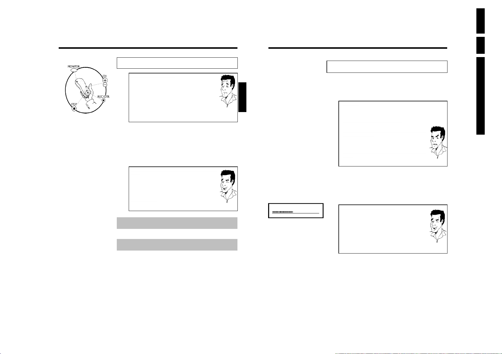
EN 28 DVDR70 & DVDR75/0x13.
H
Manual recording
General
Which discs can I use for recording?
With this DVD recorder, you can record on two types of DVD:
DVD+RW
This disc can be written to and then the contents deleted.
DVD+R
This type of disc can only be recorded once.
If you want to play this DVD in a DVD player it must be finalized using the
'Finalise disc' function. It is not possible to make further recordings using
this disc.
If this disc is to be played in a DVD recorder it must not be finalised.
Recordings can be added and deleted. The disc space (playback time) from the
deleted recording cannot be recovered for further recordings
Use the 'Manual recording' function to spontaneously start recording (e.g. to record a TV show
already in progress).
In the 'index display' select the title to be overwritten or 'Empty title' with CH- B , CH+ A .
If you insert recordings between existing recordings, check the lengths of the old and new
recordings. If the new recording is too long the subsequent recording (title/chapter) will be
overwritten.
Insert new recordings at the end of all existing recordings (Safe
Record)
To add a new recording at the end of the last recording on the disc, hold
down the REC/OTR n button until the message 'SAFE REC' appears on the
display.
For DVD+R discs each new recording is always added at the end of all
previous recordings as existing recordings cannot be overwritten.
End of disc is reached
If the end of a disc is reached during recording, recording will stop and the
Recorder will turn itself off automatically.
Please refer to section 'Recording without automatic switchoff', if you want to manually
start and stop your own recording.
If you want to start a recording manually but have it stopped automatically, read the section
'Recording with automatic switchoff'. (e.g. not to record to the end of the disc)
Read the section 'Automatic recording from a satellite receiver', if you want a recording
to be controlled automatically by a satellite receiver.
Read the section 'Direct record' if you want to record a programme currently being shown.
Tip
Recording without automatic switchoff
1 Switch on the TV set and select the programme number for the DVD
recorder.
2 Insert a disc on which the recording is to be made. This disc is then
checked for content and system. READING' will appear on the display.
ENGLISH
?
1 FREETITLE P01
aIndex display
b A DVD+RW disc has been inserted that already contains recordings. Use
the CH+ A or CH- B button to select the point where the recording is
to start.
The message 'EMPTYDISC' appears in the display
a
b The disc inserted is a blank DVD disc.
A dialog box appears asking you whether you want to delete the
a
contents or eject the disc
b The disc inserted is a DVD+RW but its contents are not DVD
video-compatible (e.g. a data disc). Recordings on this disc can only be
made if the entire disc is first deleted with the REC/OTR n button.
The message 'Title limit' appears on the screen if a recording is to
a
be made
b A disc may contain a maximum of 48 titles (including blank titles). Delete
titles or change the disc.
3 If necessary, use the MONITOR button on the remote control to
switch to the internal tuner in the DVD recorder.
4 Use CH+ A or CH- B to select the programme number (station
name) you want to record. This will appear on the display:
Programme numbers of the external inputs:
'EXT1' Scart socket at the back EXT 1 TO TV-I/O
'EXT2' Scart socket at the back EXT 2 AUX-I/O
'CAM1' Front SVHS/audio sockets S-VIDEO / left AUDIO right
'CAM1' Front video/audio sockets A/V S-VIDEO / left AUDIO right
Switching between the S-VIDEO and VIDEO sockets takes place
automatically. If both sockets are in use, the signal at the
S-VIDEO socket has priority.
'CAM2' Digital Video (i Link) front socket DV IN
5 To start recording, press REC/OTR n on the remote control or
RECORD on the DVD recorder.
If you want to start the recording at the end of the existing
recordings, hold down the REC/OTR n button until the message
'SAFE REC' appears on the display.
For DVD+R discs each new recording is always added at the end of
all previous recordings as existing recordings cannot be overwritten.
This will, for example, appear in the display:
Directions For Use
Problem
Tip
Manual recording
45
46
Manual recording
Page 29
C01 1:16:51 P01
Insert chapter markers
During recording you can mark scenes so you can find them or hide them
later.
During recording, press FSS & at the start point. 'Inserting marker'
appears on the TV screen. In the display, the number of the 'CHAPTER'
increases by one.
For further information on titles and chapters, see the section on 'Changing to
another title/chapter' in 'Playback'.
6 Use the STOP h button on the remote control or h on the
machine to stop the recording. 'MENU UPDT' will appear on the display.
The DVD recorder is writing the list of contents. Wait until the
message disappears from the display. The recording is then complete.
aThe display will read 'DISC ERR'
b Recording could not be completed correctly because of a disc error. Check
the disc and clean it if necessary.
Making recordings on DVD+R discs compatible
If you want to play back the recording on a DVD player, you need to finalise
the disc in the DVD recorder. You can prepare your DVD for use in a DVD
player using the 'Finalising' feature. See 'Finalising DVD+R discs' in 'Managing
the disc contents'.
Interrupt recording (Pause)
1 During recording press PAUSE 9 , for example to avoid recording
the commercials.
2 To continue recording, press REC/OTR n .
End recording
To end the recording, press the STOP h button. Wait until 'MENU UPDT'
disappears from the display.
Tip
Problem
Tip
Tip
ENGLISH
Recording with automatic switchoff
(OTR onetouchrecording)
1 Insert a disc.
2 If necessary, use the MONITOR button on the remote control to
switch to the internal tuner in the DVD recorder.
3 Use CH+ A or CH- B to select the programme number (channel
name) you want to record.
4 Press REC/OTR n on the remote control.
5 Each time you press REC/OTR n you will add 30 minutes to the
recording time.
How can I cancel the recording time I have just entered?
To delete an entry, press CLEAR while the display shows the recording
time.
?
Preventing accidental erasing of discs
To ensure you don't accidentally delete a recording you can protect the entire disc. You can
only ever protect the entire disc. You cannot protect individual recordings.
What happens with DVD+R discs?
As long as these discs are not finalised, they can be protected against
accidental erasure in the same way as DVD+RW discs.
1 Insert the disc to be protected.
2 While the index screen is displayed press STOP h on the remote
control. The first title is highlighted.
3 Press CH+ A . This takes you to the disc info screen.
4 Press the C button.
Select the 'Protection' line.
Confirm with C .
5 Select 'Protected' with the CH- B button and confirm with OK .
6 Press D and then DISC-MENU to terminate.
?
Directions For Use
Manual recording
47
48
EN 29DVDR70 & DVDR75/0x1 3.
Manual recording
Page 30
EN 30 DVDR70 & DVDR75/0x13.
The entire disc is now protected.
If an attempt is made to record on a protected disc, 'DISC LOCK' will appear on the display and
'Disc locked' will appear on the screen.
Lining up recordings within a title
(assemble cut)
On a recorded DVD+RW disc you can add another recording to an existing title. This recording
is added to the title as a 'chapter'. The existing information will be overwritten starting from this
point. Titles will also be overwritten that follow the current title depending on the length of the
new recording. The recording type (Quality) will be taken from the current title.
To play back this recording, press SYSTEM-MENU and use the C button to select the 'C'
(Chapter) symbol. You can also use the T/C key.
For further information, see 'Changing to another title/chapter' in 'Playback'.
What happens with DVD+R discs?
New recordings on 'DVD+R' discs can only be added after existing recordings.
It is not possible to overwrite existing recordings on 'DVD+R' discs.
1 In the index display, find the title to which the new recording is to be
added.
2 Look at the last minute of the old recording (playback)
3 Press PAUSE 9 on the remote control at the position where the
new recording is to go. '9' will appear on the screen.
4 To monitor the recording you can press MONITOR to switch to the
internal tuner.
5 Now start recording as usual by pressing REC/OTR n on the
remote control.
The new recording will be inserted.
6 Stop recording with STOP h .
?
ENGLISH
Selecting the recording type (Quality)
You can select the picture quality of the recording using the recording quality feature and hence
the maximum recording time per disc.
You can check the quality by changing the recording mode and then watching the picture from
the built-in tuner ( MONITOR button).
During playback, the correct picture quality will automatically be selected.
1 Switch on the TV set. If required, select the programme number for
the DVD recorder.
Select the record mode with the button REC MODE on the remote
control.
Which recording types can I choose?
'M1': High Quality offers the best picture quality and a recording time of 1
hour.
'M2': Standard Play (pre-recorded DVD quality) offers standard picture quality
and a recording time of 2 hours.
'M2x': Standard Play plus (better than S-VHS quality) offers standard picture
quality and a recording time of 2.5 hours.
'M3': Long Play (S-VHS picture quality). Recording time of 3 hours.
'M4': Extended Play (better than VHS picture quality). Recording time of 4
hours.
'M6': Super Long Play (VHS picture quality). Recording time of 6 hours.
Can I select the recording type via a menu as well?
1
Press the SYSTEM-MENU button.
2
Select 'A' symbol with D or C .
3
Select 'Record settings' using CH- B or CH+ A and confirm with
C .
4
In the line 'Record mode' select the recording type with D or C .
5
Confirm using OK and SYSTEM-MENU .
6
If you have selected the recording mode 'M3', 'M4'or'M6', you can
select the settings 'Stndrd' (Standard) or 'Sport' (for rapid movements)
in the 'Filter mode' line.
Tip
Directions For Use
Manual recording
49
50
Manual recording
Page 31
Automatic recording from a satellite
receiver (Sat recording)
You can use this function if you own a satellite receiver that can control other devices via a
scart cable and a programming function (timer). For more information, please see the operating
instructions for the satellite receiver.
1 Switch on the TV set. If required, select the programme number for
the DVD recorder.
2 Press SYSTEM-MENU on the remote control. The menu bar
appears.
3 Select '
4 Select 'Record settings' using CH- B or CH+ A and confirm with
5 Select 'Sat record' using CH- B or CH+ A .
6 Select 'EXT2' with D or C .
7 Confirm with OK .
8 Use a scart cable to connect scart socket EXT 2 AUX-I/O on the
9 To end, press SYSTEM-MENU .
0 Insert a disc you want to use for recording.
A Programme the satellite receiver with the required information
B Switch off the DVD recorder using STANDBY m .'SAT' also
' symbol with D or C .
A
C .
Switching off 'Sat Recording'
To switch off the function, select 'Off' using C or D .
DVD recorder to the corresponding scart socket on the satellite
receiver.
(programme number of the TV channel, start time, end time).
If necessary, please see the operating instructions for your satellite
receiver.
appears in the display to indicate that the function is active.
Tip
ENGLISH
Direct Record
Can you record the right TV channel in seconds when the DVD recorder is switched off? No
problem. If recording is started manually, the switchedoff DVD recorder takes the current TV
channel from the TV set via the scart cable.
You will find more information on how to switch 'Direct record' on or off in the next section
'Direct record'.
How does Direct Record work?
The DVD recorder compares the TV channel selected on the TV set with its
stored TV channels via the scart cable. If the same TV channel is found, it
switches the DVD recorder to the corresponding programme number and
starts recording.
Please do not change channel on the TV during the search. This could affect
the tuning of the DVD recorder.
1 On the TV set, select the programme number you want make the
recording from.
2 Press REC/OTR n with the DVD recorder switched off.
aThe display will read 'WAIT'
b The DVD recorder is comparing its saved TV channels with those of the
TV set. Please do not change the TV channel on the TV set while 'WAIT'is
shown in the display.
'NOTV' appears in the display
a
b This TV channel could not be found in the DVD recorder's memory.
Check that all TV channels saved on the TV set are available on the DVD
recorder. If required, save any missing channels. Please read 'Manual TV
channel search' in 'Installing your DVD recorder'.
b Check the connectors at both ends of the scart cable.
b Check your TV's operating instructions to see which scart socket is used
for video signals.
b If the problem persists, you won't be able to use this feature.
3 Stop recording with STOP h .
?
Problem
Directions For Use
Manual recording
The DVD recorder is now ready to record. The start and end of the recording is controlled via
scart cable EXT 2 AUX-I/O .
51
52
EN 31DVDR70 & DVDR75/0x1 3.
Manual recording
Page 32
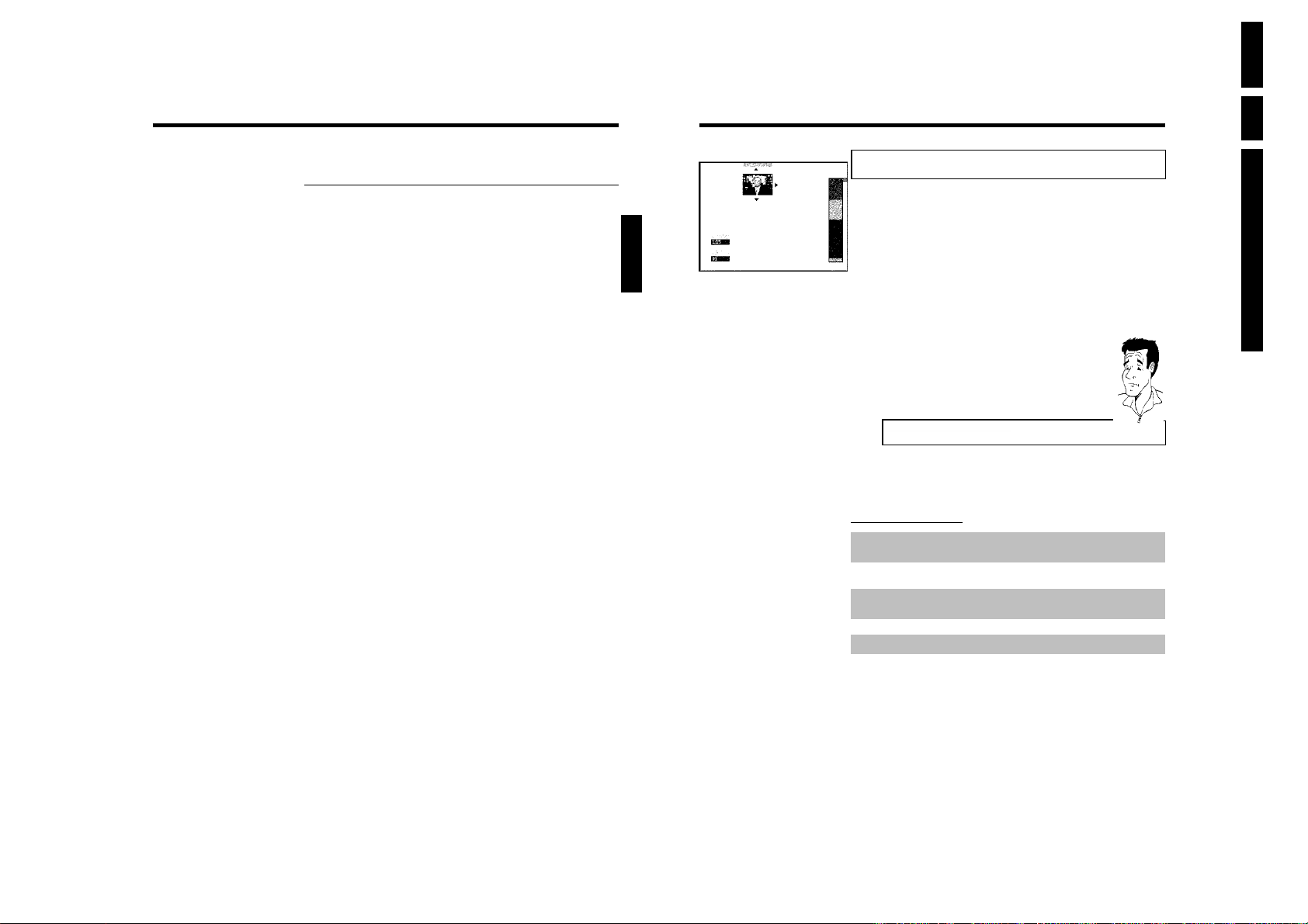
EN 32 DVDR70 & DVDR75/0x13.
Switching 'Direct Record' on or off
1 Switch on the TV set. If required, select the programme number for
the DVD recorder.
2 Press SYSTEM-MENU on the remote control. The menu bar
appears.
3 Select '
4 Select 'Record settings' using CH- B or CH+ A and confirm with
5 Select 'Direct Record' using CH- B or CH+ A .
6 Select 'On' (Direct Record on) or 'Off' (Direct Record off) using
7 Confirm with OK .
8 To end, press SYSTEM-MENU .
9 Switch off with STANDBY m .
' symbol with D or C .
A
C .
D or C .
ENGLISH
I
Managing the disc contents
Charly 1
00:29:59 • M1
Fri15/02/2003
Empty title
01:30:01
General
When a recording is made to disc, the following additional information is also stored at the
beginning of the recording:
•) Name of the recording
If the TV station does not transmit a name, only the
channel number and time will be stored as the name
•) Length of the recording
•) Record type (Quality)
•) Date of the recording
•) Index picture of the recording
A marker will be set every 5-6 minutes if the 'Auto chapters' function is activated in the
'Record settings' menu. This marker is known as a 'chapter'.
These markers can be changed when the recording has finished.
Can markers be set on a DVD+R disc?
Markers can be set on these discs if they have not been finalised.
It is also possible to add 'chapters' later. This means that scenes you do not want to see during
playback, such as commercials, can be hidden or skipped. During playback you can watch your
recording as a continuous sequence without the hidden chapters.
Select from the following chapters:
'Favorite Scene Selection',
to divide the title into chapters or to manage the chapters.
'Editing recording titles (name)',
to change the recording names.
'Play complete title',
to play the entire title including the hidden chapters.
'Delete recording/title'to delete the relevant title and therefore also the recording.
'Disc settings'to change the general settings of the disc.
Directions For Use
?
Manual recording
53
54
Managing the disc contents
Page 33
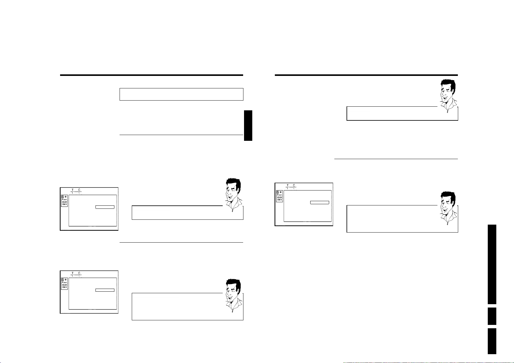
Favorite Scene Selection
3 Using C select 'hidden'. The picture is shown darker.
Favorite Scene Selection
Insert marker Press OK
Current chapter visible
Delete marker
Delete all markers
New index picture
Divide title
Favorite Scene Selection
Insert marker Press OK
Current chapter visible
Delete marker
Delete all markers
New index picture
Divide title
In this menu you can adapt a title to suit your particular needs.
You can insert/delete chapter markers, hide chapters, select a new index, or split up a title.
Press FSS & on the remote control during recording to open this menu.
Insert chapter markers
During recording, you can set or delete chapter markers within a title.
The maximum number of chapters per disc is 124 and 99 per title. If one of these limits is
reached the following message will appear on the screen: 'Chapter limit'. You need to delete
some markers before you can insert new ones or make recordings.
1 During playback, press FSS & on the remote control at the
appropriate point. The 'Favorite Scene Selection' menu appears on
the TV screen.
2 Confirm 'Insert marker' by pressing OK .'Inserting marker'
appears on the TV screen.
'X' will appear on the screen:
This DVD is write-protected or the disc is a finalised DVD-R. Subsequent
changes cannot be made.
Press FSS to exit
3 To stop this function, press FSS & .
Hiding chapters
Initially, all the chapters are visible. You can hide chapters for playback (e.g. advertisements) or
make them visible again. In editing mode, hidden chapters are shown as dimmed.
1 While the relevant chapter is playing, press FSS & on the remote
control. The 'Favorite Scene Selection' menu appears on the TV
screen.
How can I select different chapters?
1
Press the T/C button on the remote control. Titles and chapters are
Press FSS to exit
displayed at the top of the screen.
2
Select title (T) or chapter (C) with C or D .
3
Use CH+ A or CH- B to select the title/chapter channel you want to
edit.
Tip
Tip
ENGLISH
Favorite Scene Selection
Insert marker Press OK
Current chapter visible
Delete marker
Delete all markers
New index picture
Divide title
Switching quickly
You can switch between show chapters ('visible') and hide chapters
('hidden') quickly and easily using SELECT .
4 To end, press FSS & .
During playback this chapter will be skipped.
If the chapter is not visible, select 'visible' in step
Deleting chapter markers
Within a title you can delete either all markers or individual markers.
1 While the relevant chapter is playing, press FSS & on the remote
control. The 'Favorite Scene Selection' menu appears on the TV
screen.
How can I select different chapters?
1
Press the T/C button on the remote control. Titles and chapters are
Press FSS to exit
displayed at the top of the screen.
2
Select title (T) or chapter (C) with C or D .
3
Use CH+ A or CH- B to select the title/chapter channel you want to
edit.
2 Use CH- B to select either 'Delete marker' for this chapter or
'Delete all markers' for all chapters within the selected title.
3 Confirm with OK .
4 To end, press FSS & .
3
Tip
with C .
Directions For Use
Tip
Managing the disc contents
2 Select 'Current chapter' using CH- B .
55
56
EN 33DVDR70 & DVDR75/0x1 3.
Managing the disc contents
Page 34
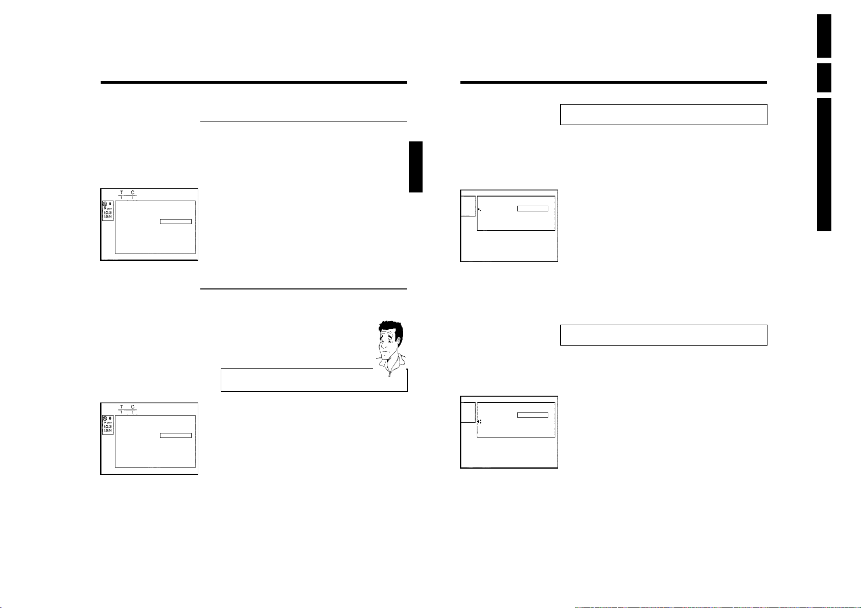
EN 34 DVDR70 & DVDR75/0x13.
Favorite Scene Selection
Insert marker Press OK
Current chapter visible
Delete marker
Delete all markers
New index picture
Divide title
Favorite Scene Selection
Insert marker Press OK
Current chapter visible
Delete marker
Delete all markers
New index picture
Divide title
Changing the index picture
Normally the first picture of a recording is used as the index picture. You can however choose
any picture from the recording as the index picture.
1 During playback, search for location of the new index picture. Press
the PAUSE 9 button.
2 Press the FSS & button. The 'Favorite Scene Selection' menu
appears on the TV screen.
3 Select line 'New index picture' and confirm with OK .
4 Start the change with OK .'Updating menu' appears on the TV
screen.
Press FSS to exit
Once the revision has been completed successfully the DVD recorder reverts to the index
overview.
Splitting titles
You can split a title into several sections (titles) of any size. Each of these sections (titles) is
identified by its own index.
Note: This split cannot be undone.
Can I split titles on DVD+R discs?
As recordings on DVD+R discs cannot be overwritten, it is not possible to
split titles.
1 While the relevant title is playing, press FSS & on the remote
control. The 'Favorite Scene Selection' menu appears on the TV
screen.
2 Select 'Divide title' and confirm with the OK button.
3 If you are sure, press OK to start the process. 'Dividing title'
appears on the TV screen.
Press FSS to exit
4 Wait until the new title is displayed with an index picture in the index
picture overview.
Editing recording titles (name)
Some TV stations transmit the title (name) of a programme. In this case, the name will be
included automatically (e.g. 'ROCKY'). Otherwise, the only the programme number (programme
name) and the time are stored as the name of the recording. The name of the recording can
only be changed after the recording has been completed.
ENGLISH
Settings for title Charly 1
Name Charly1
Play full title
Erase this title
1 Press the STOP h button or during playback press DISC-MENU .
2 Using CH+ A or CH- B select the title whose name you want to
edit and confirm with C . The menu for editing names appears.
3 Select 'Name' using CH+ A or CH- B and confirm with C .
4 Using C or D select the position where the letter/number/icon is to
be changed/re-entered.
5 Change the icon using CH+ A or CH- B . You can switch between
upper and lowercase using SELECT . You can delete the character
using CLEAR .
6 Repeat
7 Save the new name with OK .'Storing name' appears on the TV
4
and5until you have made the changes you want.
screen for confirmation.
Directions For Use
8 To end, press D .
Playing the entire title
If you have hidden certain sections (chapters) of a title, this setting lets you watch the entire title
including the hidden sections. To do this, proceed as follows:
?
Settings for title Charly 1
Name Charly1
Play full title Press OK
Erase this title
1 Press the STOP h button or during playback press DISC-MENU .
2 Using CH+ A or CH- B select the title you want to play all of and
confirm with C . The title editing menu will appear.
3 Select 'Play full title' using CH+ A or CH- B and confirm with
OK .
4 Playback starts automatically. The title is played in its entirety -
including the hidden chapters.
Managing the disc contents
The process of splitting the title is now complete.
57
58
Managing the disc contents
Page 35
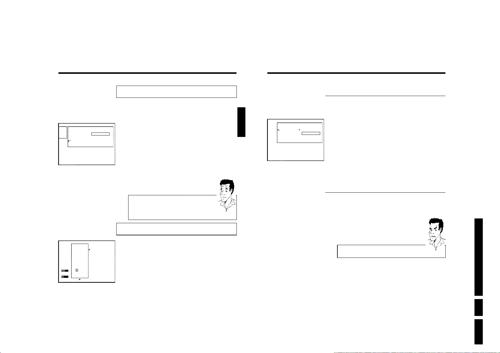
Deleting recordings/titles
Changing the disc name
Settings for title Charly 1
Name Charly1
Play full title
Erase this title Press OK
Philips1
00:35:59 used
Fri15/02/2003
PAL
DVD playback
You can delete specific recordings from a disc. To do this, proceed as follows:
1 Press the STOP h button or during playback press DISC-MENU .
2 Using CH+ A or CH- B select the title you want to delete and
confirm with C . The title editing menu will appear.
3 Select 'Erase this title' using CH+ A or CH- B and confirm with
OK .'This will completely erase this title' appears on the TV
screen.. 'Press OK to confirm'.
4 If you want to delete this title, press OK to confirm. Otherwise press
D .
5 'Erasing title' appears on the TV screen.
6 At this point 'Empty title' appears in the 'index picture display'. A
new recording can now be made here.
If the deleted title was very short (less than 1 minute) 'Empty title'
will not appear at this point.
Can titles be deleted from a DVD+R disc?
Titles on DVD+R discs are only marked as deleted. 'Deleted title' will appear
in the display instead of 'Empty title'. During playback the 'deleted' title is
skipped. The space used for this title cannot be used again as the title has not
been physically deleted. Once the disc has been finalised no further changes
can be made.
?
Disc settings
This screen appears beforethe first title and contains general information about the current disc.
You can:
•) change the name of the disc
•) activate or deactivate write protection on the disc
•) Finish editing (make the disc DVD compatible)
•) finalise a DVD+R
•) delete a DVD+RW
To get to this display, proceed as follows:
ENGLISH
Settings for Philips1
Disc name Philips1
Protection Unprotected
Erase disc
1 In the 'Disc info display' press C . The 'Settings for' menu appears
on the TV screen.
2 Select 'Disc name' using CH+ A or CH- B and confirm with C .
3 Using C or D select the position where the letter/number/icon is to
be changed/re-entered.
4 Change the icon using CH+ A or CH- B . You can switch between
upper and lowercase using SELECT . You can delete the character
using CLEAR .
5 Repeat
6 Save the new title with OK .'Storing name' appears on the TV
7 To end, press D .
3
and4until you have made the changes you want.
screen for confirmation.
Finishing editing
If one or more titles have been edited a DVD player may still display the original titles. You can
prepare your disc in such a way that a DVD player will be able to play the edited version.
1 In the 'Disc info display' press C . The 'Settings for' menu appears
on the TV screen.
2 Select 'Make edits compatible' using CH+ A or CH- B and
confirm with OK .
a'Make edits compatible' does not appear
b Your disc is already compatible. There is no need for conversion.
To end, press SYSTEM-MENU .
3 The screen displays 'This will take' to show how long the process
will last.
4 To confirm press OK .'Working' appears on the TV screen. A bar
will move from left to right indicating progress.
Problem
Directions For Use
Managing the disc contents
1 Press the STOP h button or during playback press DISC-MENU .
2 Select the first title with CH+ A or press STOP h .
3 Press the CH+ A button. The disc info display will appear.
59
60
EN 35DVDR70 & DVDR75/0x1 3.
Managing the disc contents
Page 36
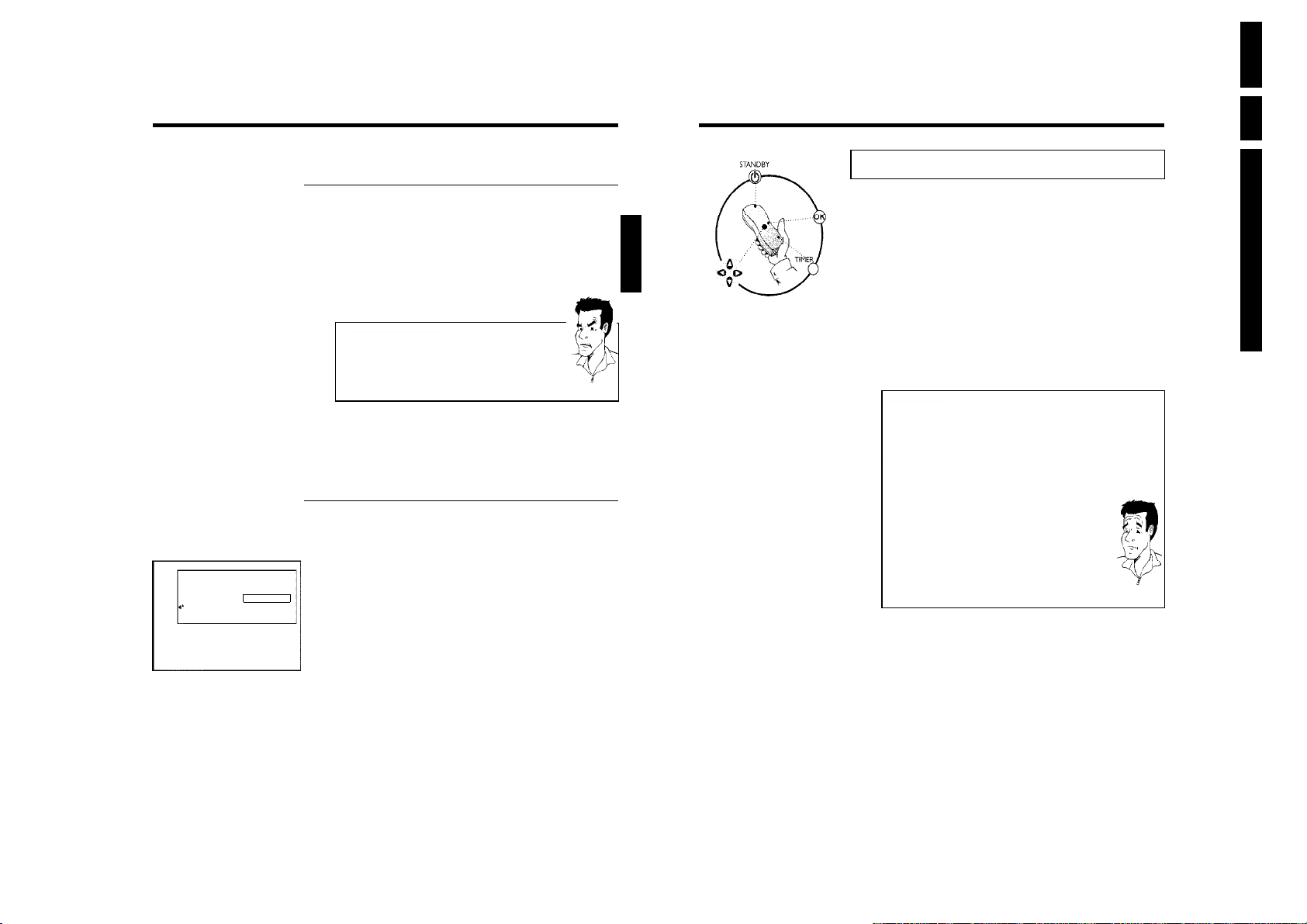
EN 36 DVDR70 & DVDR75/0x13.
Settings for Philips1
Disc name Philips1
Protection Unprotected
Erase disc Press OK
Finalising DVD+R discs
This feature is required to play back a DVD+R disc in a DVD player. Once the disc has been
finalised no further recordings or changes can be made.
1 In the 'Disc info display' press C . The 'Settings for' menu appears
on the TV screen.
2 Select 'Finalise disc' using CH+ A or CH- B and confirm with
OK .
a'Finalise disc' does not appear
b Either there is no DVD+R disc inserted or the disc is already finalised.
To end, press SYSTEM-MENU .
The 'Settings for' menu does not appear
a
b The menu may not appear if the disc has been recorded on another DVD
recorder. In this case, use the 'Finalise disc' feature in the '
under 'Features'.
3 The screen displays 'This will take...' to show how long the process
will take.
4 To confirm press OK .'Working' appears on the TV screen. A bar
will move from left to right indicating progress.
A
' menu,
Problem
Delete DVD+RW disks
1 In the 'Disc info display' press C . The 'Settings for' menu appears
on the TV screen.
2 Select 'Erase disc' using CH+ A or CH- B and confirm with OK .
'This will erase all titles' appears on the TV screen. Press OK to
confirm'.
3 If you want to delete all the titles, press OK to confirm. Otherwise
press D .
4 'Erasing disc' appears on the TV screen.
5 After deletion, the index picture display shows the free space on the
disc.
ENGLISH
J
Programming a recording (TIMER)
General
Use 'Programming a recording (TIMER)', to automatically start and stop a recording at a later
date.
The DVD recorder will switch to the right programme number and begin recording at the
correct time.
With this DVD recorder, you can pre-programme up to six recordings within a period of one
month.
To make a programmed recording, your DVD recorder needs to know:
* the date you want to make the recording
* the programme number of the TV channel
* the start and stop time of the recording
* VPS or PDC on or off
* the recording mode ('M1/M2/M2x/M3/M4/M6')
This information is saved in a 'TIMER block'.
What is 'VPS/PDC'?
'VPS' (Video Programming System)/'PDC' (Programme Delivery Control) are
used to control the start and duration of TV channel recordings. If a TV
programme starts earlier or ends later than was scheduled, the DVD recorder
will then turn on and off at the correct time.
What do I need to know about 'VPS/PDC'?
• Usually the start time is the same as the VPS or PDC time. If a different
'VPS/PDC time' is indicated, e.g.: '20.15 (VPS/PDC 20.14)', the VPS/PDC time
'20.14' must be entered exactly to the minute during programming.
If you want to programme a time that is different from the VPS or PDC time,
you must switch off VPS or PDC.
• Only one TV program of a TV channel can be controlled using 'VPS/PDC' at a
time. If you want to record two or more TV programmes on a TV channel
using 'VPS/PDC', you will need to programme these as two separate
recordings.
• Since the DVD recorder requires a certain lead time (for getting the disc up to
speed and positioning the laser) before recording can start, it is possible that
the recorder will miss the first few seconds of a TV show recorded with
VPS/PDC.
In this case, disable VPS/PDC and enter a start time one minute earlier.
Directions For Use
?
Managing the disc contents
61
62
Programming a recording (TIMER)
Page 37
Timer
ShowView system
ShowView number
---------
Programming recordings with the
ShowView
Thanks to this programming system, you no longer need to tediously enter the date, programme
number, start and end times. All the information needed by the DVD recorder for programming
is contained in the ShowView
most TV listings magazine.
1 Switch on the TV set. If required, select the programme number for
the DVD recorder.
2 Press TIMER on the remote control.
The programming method selected last is marked.
3 Select 'ShowView system' using CH- B or CH+ A and confirm
with C .
4 Enter the entire ShowView number. This number is up to 9 digits long
and can be found next to the start time of the TV programme in your
TV listings magazine.
e.g.: 5-312-4 or 5,312 4
Enter 53124 for the ShowView-number.
If you make a mistake, you can clear your instructions with CLEAR .
®
System
®
programming number. This 9-digit ShowView®number is found in
Selecting daily/weekly recordings
Using SELECT , select from the following options:
'Mo-Fr': Repeated daily recordings (Monday to Friday).
'Weekly': Repeated weekly recordings (every week on the same day).
Tip
ENGLISH
Timer
ShowView system
Date01Prog.
BBC1
Mo-Fr/Weekly
Press SELECT
Start
20:15
VPS
PDC End
21:30
6 The decoded data appears after confirmation. You can go back and
Rec
Mode
M2
To store
Press OK
change the data. Select the appropriate input field with C or D .If
required, make changes using CH+ A , CH- B or the number
buttons 0..9 .
'Switching on 'VPS/PDC' in the 'Start' input field
Select the 'Start' input field using C . Using SELECT switch on 'VPS/PDC'
('*' lights up). If you press SELECT again, you will switch 'VPS/PDC' off ('*'
goes out).
Changing the recording mode in input field 'End'
Select the 'End' input field using C .
Use SELECT to select the recording mode 'M1, M2, M2x, M3, M4, M6'.
7 If all information is correct, press the OK button. The programming
information is stored in a TIMER block.
8 To end, press TIMER .
9 Insert a recordable disc (one without write protection).
The disk you have inserted will be checked.
0 Switch the DVD recorder off with STANDBY m .
The programmed recording will only function properly if the DVD
recorder has been switched off using the STANDBY m button.
If any of the TIMER blocks are in use, 'TIMER' will light up on the recorder display.
Tip
Directions For Use
Mo-Fr/Weekly
Press SELECT
To store
Press OK
5 Confirm with OK .
Programming a recording (TIMER)
aThe following message appears on the screen: 'Please enter
programme number'
b The programme number of the TV channel has not yet been assigned to
the ShowView number. Use C , D or the number buttons 0..9 on the
remote control to select the appropriate programme number (name) of the
TV channel and confirm with OK .
The following message appears on the screen: 'ShowView number
a
wrong'
b The entered ShowView number is incorrect. Correct your entry or cancel
using the SYSTEM-MENU button.
b Check the time/date (see 'Setting the time & date' in 'Installing your DVD
recorder').
The following message appears on the screen: 'Weekend
a
programming not possible'
b A daily recording was entered for the wrong day. Daily programming can
only be used for recordings to be made from Monday to Friday.
Problem
63
64
EN 37DVDR70 & DVDR75/0x1 3.
Programming a recording (TIMER)
Page 38
EN 38 DVDR70 & DVDR75/0x13.
Timer
Timer programming
Date01Prog.
BBC1
Mo-Fr/Weekly
Press SELECT
Start
20:15
VPS
PDC End
21:30
Rec
Mode
M1
To store
Press OK
Programming recordings without the
ShowView
1 Switch on the TV set. If required, select the programme number for
the DVD recorder.
2 Press TIMER on the remote control.
The programming method selected last is marked.
3 Select line 'Timer programming' with CH- B or CH+ A . and
confirm with the C button.
The information will appear on the screen.
4 Select the input field with D or C .
5 Enter information with CH- B or CH+ A or with the number
buttons 0..9 .
6 If all information is correct, press the OK button. The programming
information is stored in a TIMER block.
7 To end, press TIMER .
8 Insert a DVD (one without write protection).
The disk you have inserted will be checked.
9 Switch off with STANDBY m .
The programmed recording will only function properly if the DVD
recorder has been switched off using the STANDBY m button.
®
System
Selecting daily/weekly recordings
In 'Date' use SELECT to select from the following options:
'Mo-Fr': Repeated daily recordings from Monday to Friday
'Mon': Repeated weekly recordings (every week on the same day, e.g.
Monday).
Programme numbers of the 'EXT1' and 'EXT2'scart socket
You can also programme recordings from external sources via scart socket
EXT 1 TO TV-I/O ('EXT1') or EXT 2 AUX-I/O ('EXT2').
'Switching on 'VPS/PDC' in the 'Start' input field
Select the 'Start' input field using TIMER . Using SELECT switch on
'VPS/PDC' ('*' lights up). If you press SELECT again, you will switch
'VPS/PDC' off ('*' goes out).
Changing the recording quality in input field 'End'
Select the 'End' input field using C .
Use SELECT to select the recording mode.
Tip
ENGLISH
Timer
Timer List
Date
01
--
Total record time: 01:15
To change
Press ›
Prog.
BBC1
-----
Start
20:15
--:--
VPS
PDC*End
Rec
Mode
21:30
M2
--:--
--
To exit
Press TIMER
How to change or delete a programmed
recording (TIMER)
1 Switch on the TV set. If required, select the programme number for
the DVD recorder.
2 Press TIMER on the remote control.
The programming mode selected last is marked.
3 Select 'Timer List' using CH- B or CH+ A and confirm with C .
4 Select the programmed recording (TIMER) you want to check, change
or delete with CH- B or CH+ A .
Delete programmed recording
1
Press the CLEAR button.
2
Confirm with OK .'Timer Cleared' will briefly appear on the TV
screen.
'-- ---' appears rather than the displayed values
3
To end, press TIMER .
5 Press C .
Select the input field with D or C .
If required, change the information with CH+ A , CH- B or the
number buttons 0..9 .
6 Confirm with OK .
7 To end, press TIMER .
8 Switch off with STANDBY m .
Tip
'NexTView Link'
This DVD recorder is equipped with the 'NexTView Link' feature. If your television is also
equipped with this function, you can mark TV programmes on the television for programming.
These TV programmes will automatically be transmitted to a TIMER block on the DVD
recorder. If you clear the marking of the TV programme on the television, the corresponding
TIMER block on the DVD recorder will also be cleared.
For more information, read the instruction manual of your TV set.
Directions For Use
If any of the TIMER blocks are in use, 'TIMER' will light up on the recorder display.
Programming a recording (TIMER)
65
66
Programming a recording (TIMER)
Page 39
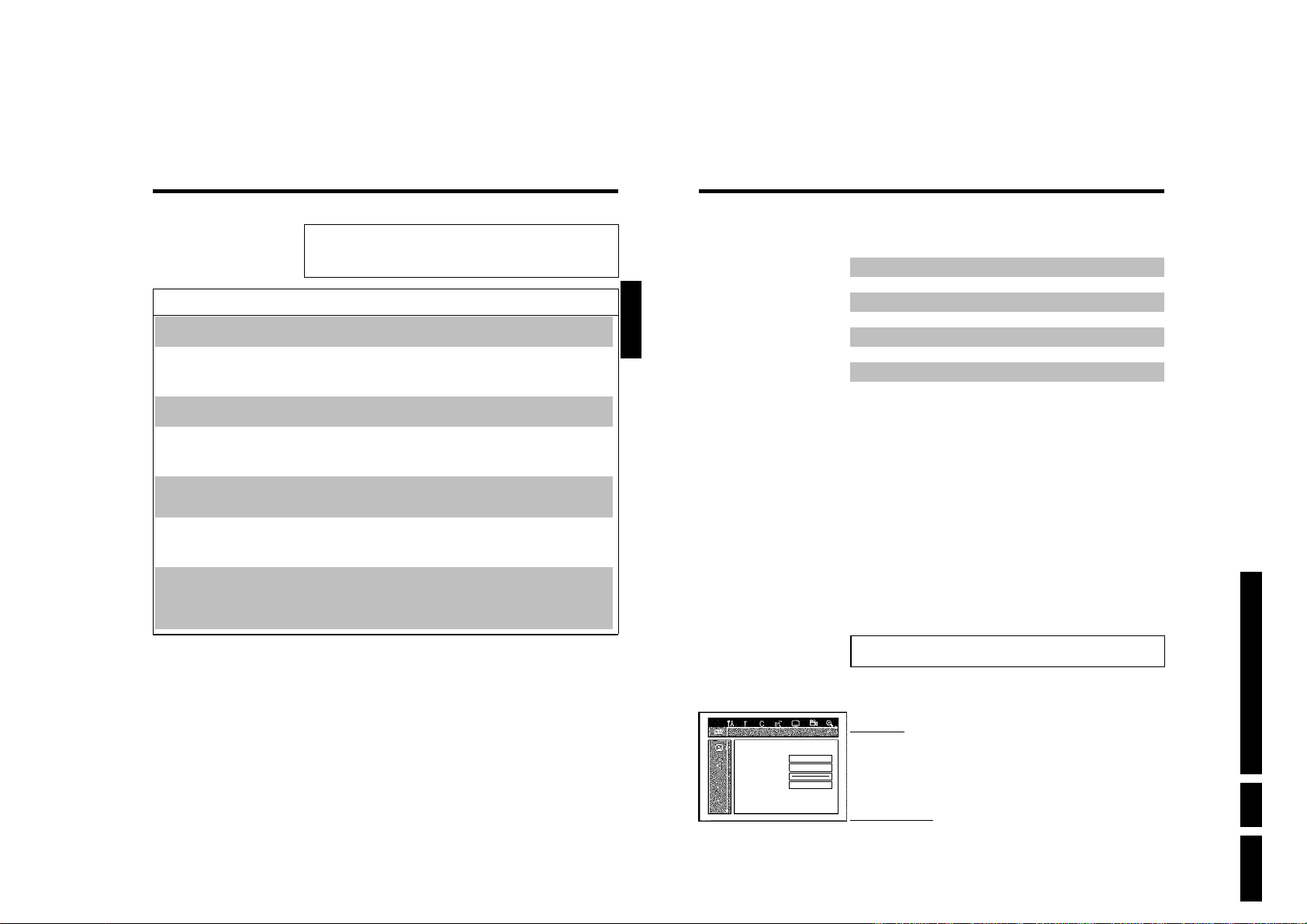
Problem solving for programmed
recordings
PROBLEM SOLUTION
The DVD recorder is
not responding
'Switch off, timer
recording' flashes on
the TV screen.
Error message: 'Insert
recordable disc'
The error message
'Disc locked' appears
briefly on the screen.
Error message:
'Memory full'
The 'Data error'
message appears on
the screen.
The 'Collision'
message appears on
the screen.
b
While a programmed recording is being made, you cannot operate your DVD recorder manually.
If you want to cancel the programmed recording, press STANDBY m .
b
The DVD recorder was switched on several minutes before the start of a programmed recording.
Switch off the DVD recorder using STANDBY m . A programmed recording (timer) will only
function if the DVD recorder is switched off ( STANDBY m button).
b
Either a disc has not been inserted or the disc cannot be used for recording. Insert a disc on
which recordings can be made. Switch off the DVD recorder using STANDBY m .
b
A write-protected disc has been inserted. Undo the write protection (see 'Preventing accidental
erasing of discs' in 'Manual recording') or insert a different disc.
b
If this error message appears after pressing TIMER , then all TIMER blocks are already
programmed. No more recordings can be programmed. Press the C button. If you want to clear
or check a programmed recording (TIMER block), select it with CH+ A or CH- B .
b
The data for the recording could not be transferred. Please check date, start time and end time
of the programmed recording.
b
Two programmed recordings overlap.
b
If you ignore this error message the show with the earlier start time will be recorded first. The
start of the second show will not be recorded.
b
Change the setting for either of the two recordings.
b
Clear either of the two recordings
ENGLISH
K
User preferences
In this section you will learn how to set your user preferences on the DVD recorder. The
symbols have the following meanings:
1 Switch on the TV set. If required, select the programme number for
the DVD recorder.
2 Press SYSTEM-MENU on the remote control. The menu bar
appears.
3 Select '
4 Select the appropriate function with CH- B or CH+ A and confirm
5 Select the appropriate line using CH- B or CH+ A and confirm
6 Select the appropriate function using CH- B or CH+ A or the
7 Confirm the new setting by pressing OK .
8 To close the menu item, press D .
' using D or C and confirm with CH- B .
A
with C .
with C .
setting with D or C .
Picture setting
Sound setting
Language setting
Additional settings
Remote control settings
Disc settings
Recording settings
Installation
Directions For Use
Programming a recording (TIMER)
67
68
TV shape 16:9
Black level shift Off
Vertical video shift ï
SCART video RGB
Picture settings
You can choose the following features in this menu:
'TV shape'
The picture signal from your DVD Recorder can be set to match your TV screen.
Picture
'4:3 letterbox': for a 'wide-screen' picture with black bars at the top and bottom
'4:3 panscan': for a full-height picture with the sides trimmed.
'16:9' : for a wide-screen TV set (screen edge ratio 16:9)
'Black level shift'
Adapts the colour dynamics for NTSC playback
EN 39DVDR70 & DVDR75/0x1 3.
User preferences
Page 40
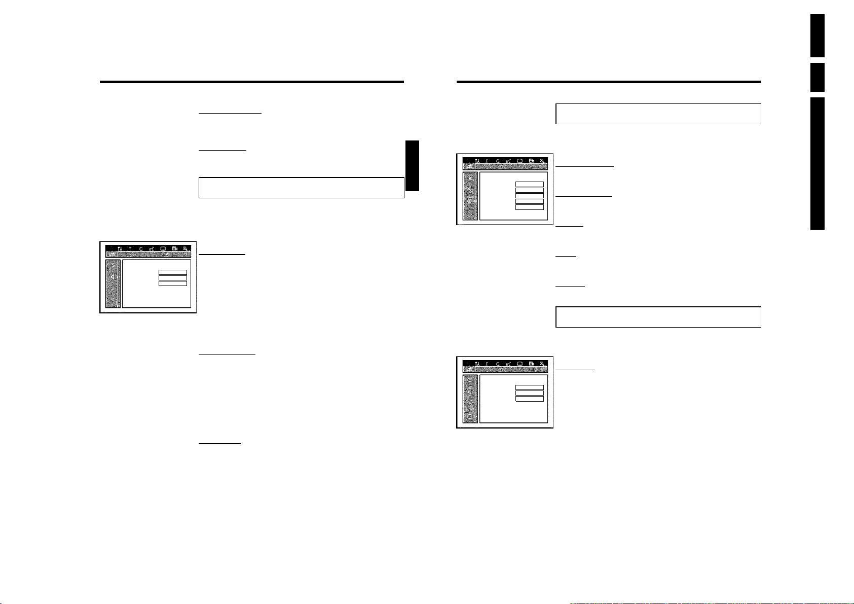
EN 40 DVDR70 & DVDR75/0x13.
Digital output All
Analogue output Stereo
Night mode Off
'Vertical video shift'
Use this feature to adjust the position of the picture on your TV left or right using D , C to
suit your TV set.
'SCART video'
By default the recorder is set to 'RGB'. Select 'S-Video' if you want to connect an S-VHS
recorder.
Sound settings
Depending on which audio outputs are used, you can select the settings in this menu.
If you only use the analogue audio output ( OUT L AUDIO R ), select the settings 'Off' in the
'Digital output' menu.
'Digital output'
For devices connected to the DIGITAL AUDIO OUT socket, you can select from the following
Sound
settings.
'All': Dolby Digital and DTS signals are fed unaltered to the digital output. MPEG-2 multi-channel
signals are converted to PCM (Pulse Code Modulation).
For receivers/amplifiers with digital multichannel sound decoders.
'PCM only: Dolby Digital and MPEG-2 multi-channel signals are converted to PCM (Pulse Code
Modulation).
For receivers/amplifiers without digital multichannel sound decoders.
'Off: Digital output switched off.
For devices with analogue audio input.
'Analogue output'
For devices connected to the analogue audio output ( OUT L AUDIO R ), you can select from
the following settings.
'Stereo': For devices without DolbySurround or TruSurround. Use this setting if the DVD
recorder is only connected to a stereo TV set.
'Surround: Dolby Digital and MPEG-2 multi-channel are mixed down to a DOLBY
surround-compatible two-channel output signal. For devices with Dolby Surround
Pro Logic decoder .
'Night mode'
Night mode optimises the sound for playback at low volume. You are therefore less likely to
disturb your neighbours. This only works for Dolby Digital audio on DVD video discs.
ENGLISH
Audio Language English
Recording audio Language 1
Subtitle English
Menu English
Country Other
Status box On
Standby Off
Display Bright
Language settings
You can choose the following settings in this menu:
'Audio Language'
Playback audio language
Language
'Recording audio'
Audio recording
'Subtitle'
Subtitle language
'Menu'
Screen menu language
'Country'
'Country'
Additional settings
You can select the following functions in this menu:
'Status box'
Along with the on screen menu, the OSD (On Screen Display) also displays information on the
Features
current operating status (counter, playback, recording, TV channel, etc.) on the TV screen.
You can switch off the information about the operating status so that the on screen display
(OSD) is not recorded during copying.
'On': The OSD information appears in every selected mode for a few seconds and disappears
again.
'Off': The OSD information is switched off. It is no longer displayed on the screen.
Directions For Use
User preferences
69
70
User preferences
Page 41
'Standby'
To save power, you can switch off the clock display on the DVD recorder. Programmed
(TIMER) recordings will still take place.
In addition, you can present the most important features of the DVD recorder in scrolling text
in the display (demo).
'Low power': If the DVD-Recorder is switched off (button STANDBY m ), the clock display is
'Off': If the DVD-Recorder is switched off (button STANDBY m ), the clock display is visible.
'Demo mode': If the DVD recorder is switched off with the STANDBY m button, a list of the
also switched off.
most important features is shown in the display.
'Display'
You can change the brightness of the display on the DVD recorder. This setting only affects the
DVD recorder when it is switched on.
'Bright': The display appear with normal brightness. The disc tray light is switched on.
'Dimmed': The display appears less bright. The disc tray light is switched off.
'Off': The display and the disc tray light are switched off.
ENGLISH
Status box On
Standby Off
Display Bright
Disk feature menu
In this menu you can make the changes that relate to the disc:
'Access control'
Please read the next chapter on 'Access control (child lock)'.
Features
'Auto resume'
If playback of a pre-recorded DVD video disc or video CD is interrupted (button STOP h or
OPEN/CLOSE J ) when the disc is reloaded (disc is started) playback starts at the precise
location where it stopped. This applies not only to the current disc but to the last 20 discs
played.
This feature can be switched off if not required.
'PBC'
This line appears only if a VCD is loaded.
This function lets you activate or deactivate the PBC menu (Playback Control) for video CDs.
See 'Playing a (Super) Video CD'.
Directions For Use
User preferences
Remote Control settings
In this menu you can set the remote control type to which your DVD recorder should respond.
'DVD player': The DVD recorder responds to a DVD player remote control.
'DVD recorder': The DVD recorder only responds to the supplied remote control.
The DVD recorder also responds to the remote control of a DVD player (remote
control code RC-6). Choose this setting if your Philips TV remote supports DVD
functions.
71
72
'Finalise disc'
This feature allows you to finalise DVD+R discs. If the disc has already been finalised this line will
appear darker.
'Adapt disc format'
If a DVD+RW has been recorded in a computer drive or in another DVD recorder the index
screen may not be displayed correctly.
This feature allows you to change the format of the disc.
It is therefore only visible if the disc format is different.
User preferences
EN 41DVDR70 & DVDR75/0x1 3.
Page 42
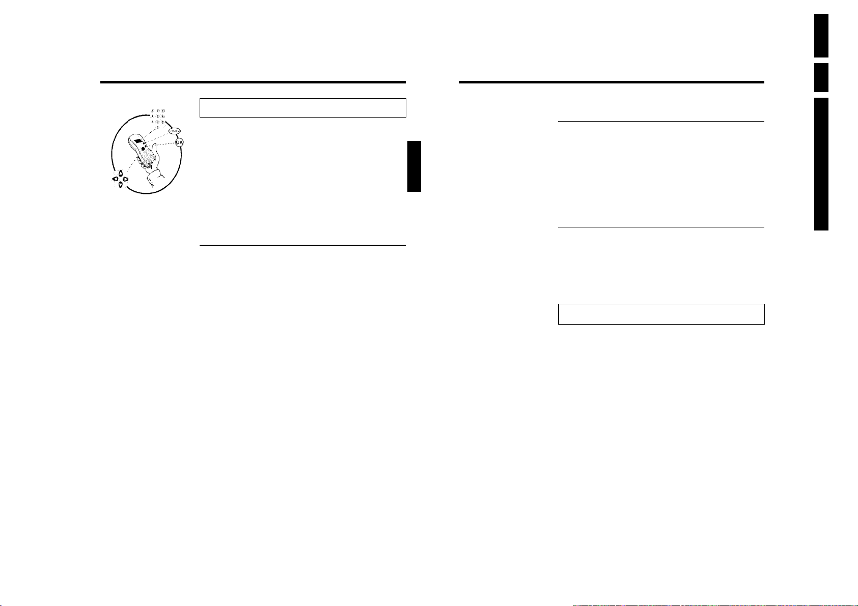
EN 42 DVDR70 & DVDR75/0x13.
L
Access control (Child Lock)
Child lock (DVD and VCD)
This feature enables discs to be locked for children.
When Child Lock is on, a 4-digit code (PIN) needs to be entered before a disc can be played.
You can also decide whether the inserted disc should always be played or should be played only
once, despite the child lock
•)'Play always':
This disc is stored in a memory with space for 50 child-safe discs. If more than 50 discs are
stored, the last disc in the list is removed and the new disc is added. The screen shows 'Child
safe' at the start of playback.
•)'Play once':
This disc is only authorised for single playback. If the recorder is switched off, the PIN code
must be re-entered.
Activating/deactivating child lock
1 Switch on the TV set. If required, select the programme number for
the DVD recorder.
2 Switch on the DVD recorder using STANDBY/ON m .
3 Press SYSTEM-MENU . The menu bar appears
4 Select the '
5 Select '
6 Confirm 'Access control' using C .
7 Enter a 4-digit code of your choice. If the code is new, you may have
8 Select 'Child lock' using CH+ A or CH- B and confirm with C .
9 Select the '
0 Confirm with OK .
A Quit the feature using D and SYSTEM-MENU .
' icon using D or C .
A
(Disc features)' using CH- B or CH+ A and confirm
with C .
to enter the code a second time as confirmation.
' icon using CH- B or CH+ A .
ENGLISH
Authorising a disc
1 Insert a disc. The access control box will appear after a short delay.
2 Using CH+ A or CH- B select 'Play once'or'Play always'.
3 Enter your PIN code using the number buttons 0..9 .
Double-sided DVDs may have a different ID for each side. For these discs, each side must be
authorised. Multi-volume video CDs may have a different ID for each volume. For these CDs,
each volume must be authorised.
Locking unlocked discs
To lock a disc that was formerly authorised follow the instructions below
1 Insert a disc. Playback starts automatically. If the playback does not
start automatically, press PLAY G .
2 Press the STOP h button while the '
changes to '
'. The disc is now locked.
' icon is visible. The icon
Parental level control (DVD video only)
Films on pre-recorded DVD discs may contain scenes not suitable for children. Therefore, some
discs may contain 'Parental Control' rating information that applies to the entire disc or to
certain scenes on the disc.
The appropriate scenes have filter values that reach from 1-8. If such a scene is detected during
playback, the filter value set on the DVD recorder is compared to the scene. If the filter value is
higher than the setting, an alternative scene will be played (if available).
Most DVDs apply the rating to an entire DVD. Therefore, if certain scenes exceed the rating
you select, the entire disc will be blocked from viewing.
Directions For Use
Access control (Child Lock)
Unauthorised discs can only be played by entering the four-digit PIN code.
To deactivate the child lock, select the '
' icon in9.
73
74
Access control (Child Lock)
Page 43
Access control Enter code…
Auto resume On
Disc features
Activating/deactivating parental level
control
1 Switch on the TV set. If required, select the programme number for
the DVD recorder.
2 Switch on the DVD recorder using STANDBY/ON m .
3 Press SYSTEM-MENU . The menu bar appears
4 Select the '
5 Select '
6 Confirm 'Access control' using C .
7 Enter a 4-digit code of your choice. If the code is new, you may have
8 Select the 'Parental level' using CH+ A or CH- B and confirm
9 Select the appropriate rating using CH- B , CH+ A or the number
0 Confirm with OK . Quit using D and SYSTEM-MENU .
' icon using D or C .
A
(Disc features)' using CH- B or CH+ A and confirm
with C .
to enter the code a second time as confirmation.
with C . A bar appears to select the parental level.
buttons 0..9 .
What do the ratings mean?
Rating 0 (displayed as '--') parental control not active.
Rating 1 (suitable for children)
Rating 8 (only suitable for adults)
What happens if a DVD scene contains a higher level than the rating
set?
If the recorder does not find a suitable alternative, playback will stop and you
must enter the four-digit code.
Tip
ENGLISH
Access control Enter code…
Auto resume On
Disc features
Changing the country
The set filter values depend on the respective country. It is therefore necessary to enter the
country to which these filter values apply.
1 Switch on the TV set. If required, select the programme number for
the DVD recorder.
2 Switch on the DVD recorder using STANDBY/ON m .
3 Press SYSTEM-MENU . The menu bar appears
4 Select the '
5 Select line '
6 Confirm the line 'Access control' using C .
7 Enter your four-digit code. If the code is new, you may have to enter
8 Select 'Change country' using CH- B or CH+ A and confirm with
9 Select the corresponding country using CH+ A or CH- B and
0 To end, press D and then SYSTEM-MENU .
' icon using D or C .
A
(Disc features)' using CH- B or CH+ A and
confirm with C .
the code a second time as confirmation.
C .
confirm with OK .
Directions For Use
Access control (Child Lock)
75
76
EN 43DVDR70 & DVDR75/0x1 3.
Access control (Child Lock)
Page 44
77
Changing the PIN code
1 Switch on the TV set. If required, select the programme number for
the DVD recorder.
2 Switch on the DVD recorder using STANDBY/ON m .
3 Press SYSTEM-MENU . The menu bar appears
4 Select the '
A
' icon using D or C .
5 Select '
(Disc features)' using CH- B or CH+ A and confirm
with C .
Disc features
Access control Enter code…
Auto resume On
6 Confirm 'Access control' using C .
7 Enter your four-digit PIN code. If the code is new, you may have to
enter the code a second time as confirmation.
8 Select 'Change code' using CH+ A or CH- B and confirm with
C .
9 Enter the new code using the number buttons 0..9 . Enter the same
code again as confirmation.
0 Quit using D and SYSTEM-MENU .
I have forgotten my code
Press STOP h four times (step 7 ), then press OK . Access control is
now switched off. You can now enter a new code as described above.
Tip
ENGLISH
Access control (Child Lock)
EN 44 DVDR70 & DVDR75/0x13.
Directions For Use
Page 45
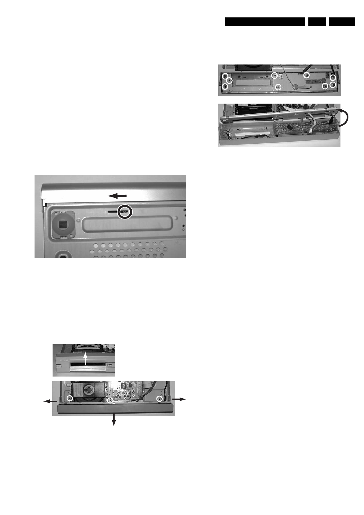
Mechanical Instructions
4. Mechanical Instructions
4.1 Dismantling and Assembly of the Set
For item numbers please see the exploded views in chapter 10.
EN 45DVDR70 & DVDR75/0x1 4.
4.1.1 Manually opening the tray
– In case the loader is defective or cannot be opened
electrically you can open the tray manually.
– Through a slot at the underside of the cabinet a slider that
unlocks the tray can be accessed.
However in sets with drive VAD8031 (AV3) the slot is
covered by an adhesive tape on the cabinet of the drive to
prevent dust coming into the drive. Push through this
adhesive tape by means of a thin screwdriver and move
the slider to the left, see picture 4-1.
– Make sure that an adhesive tape has been reapplied to
the AV3 drive when repair is finished!
5
6
Figure 4-3
Figure 4-1
4.1.2 Front
– After removing the top cover, remove tray front (1), see
picture 4-2
– Remove the three screws (2) that fix the front panel
– Release the two snap hooks on the sides (3)and remove
the front (4)
– Remove the 9 screws (5) to remove the front plate (6), see
picture 4-3
1
3
2
2
4
Figure 4-2
2
3
Page 46
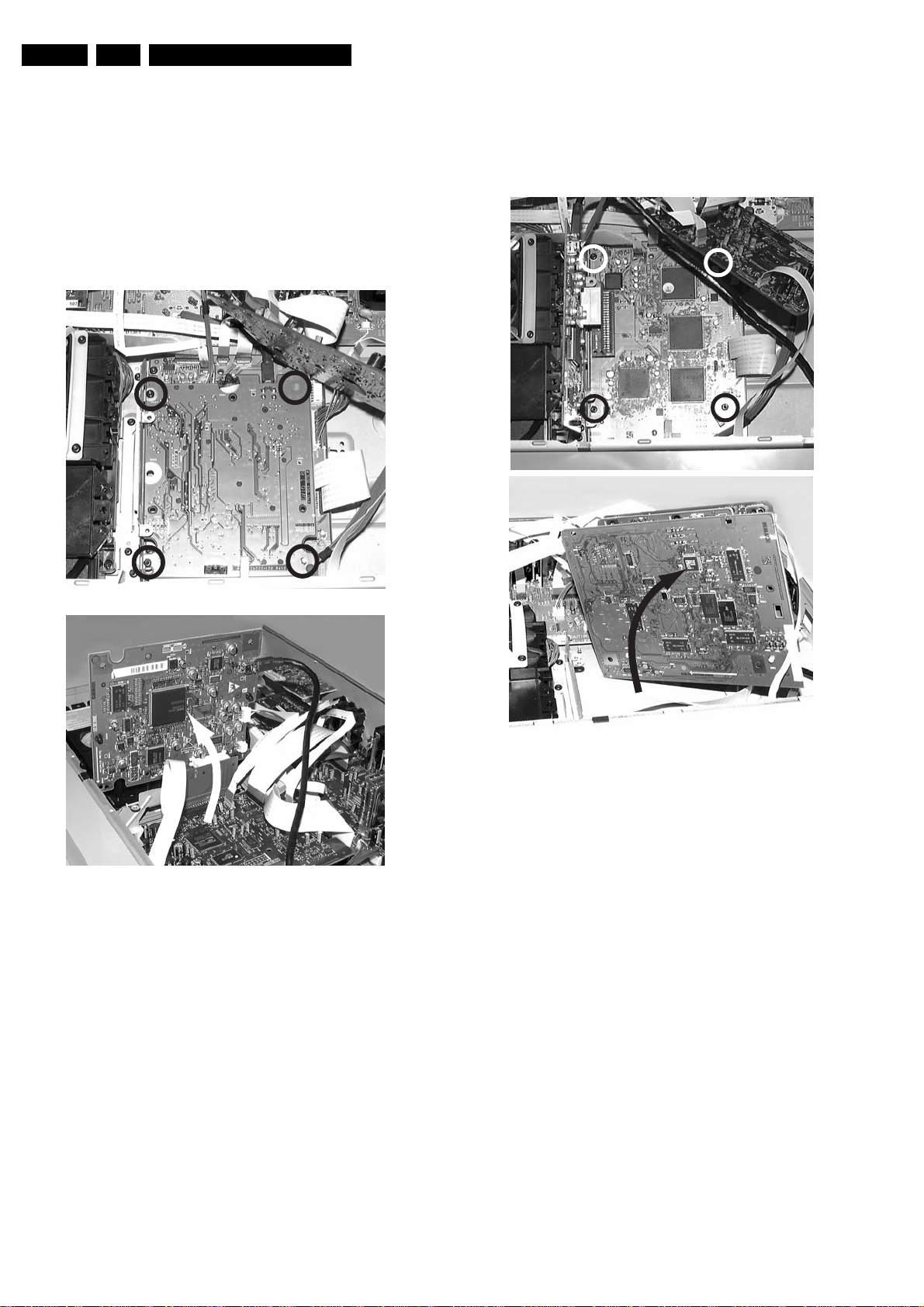
EN 46 DVDR70 & DVDR75/0x14.
Mechanical Instructions
4.1.3 DVIO Board, only for sets with DV input and Digital Board
1.5
To put the DVIO board in a service position, an extender board
must be used. This extender board can be ordered with
codenumber 3104 128 07770.
– After removal of the EPG board (if present) the DVIO board
can be reached
– Remove the two screws (1), see picture 4-4
– Release the snaps of the two board spacers 125
– Put the DVIO board in the service position with the
extender board 3104 128 07770.
1
1
1
1
4.1.4 Digital Board
– After removal of EPG board (if present) and DVIO board (if
present) the digital board can be reached
– Remove screws (1)
– Turn the PCB in the service position
1
1
1
1
2
Figure 4-4
2
Figure 4-5
Page 47
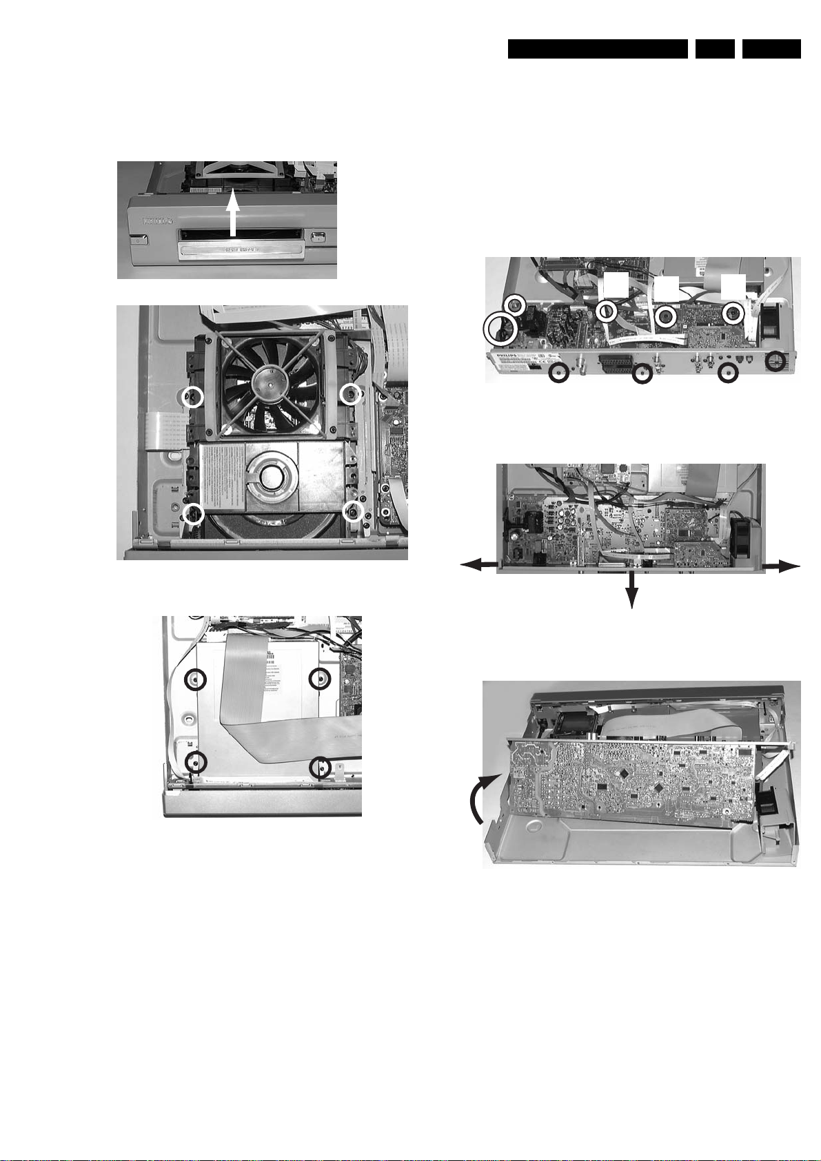
Mechanical Instructions
EN 47DVDR70 & DVDR75/0x1 4.
4.1.5 Basic Engine
– R emove the tray (1)
– Remove the four screws that fix the drive, see figure 4-6 or
4-7
1
2
2
4.1.6 Analog Board
– Remove the 3 screws (1) that fix the back plate to the
bottom plate, see picture 4-8
– Remove the 4 screws (2) that fix the Analog Board to the
bottom plate
– In sets with fan remove the Fan assy by releasing the fixing
screw (3)
– Remove screw safety holder (4)
– Unlock the two snaps hooks at the left and right (5), see
picture 4-9, and pull the board and backplate out gently (6)
– Turn the PCB in the service position (7), see picture 4-10
2
2
2
4
1
Figure 4-8
1
2
1
3
2
Figure 4-6
Figure 4-7
2
5
7
5
6
Figure 4-9
Figure 4-10
Page 48
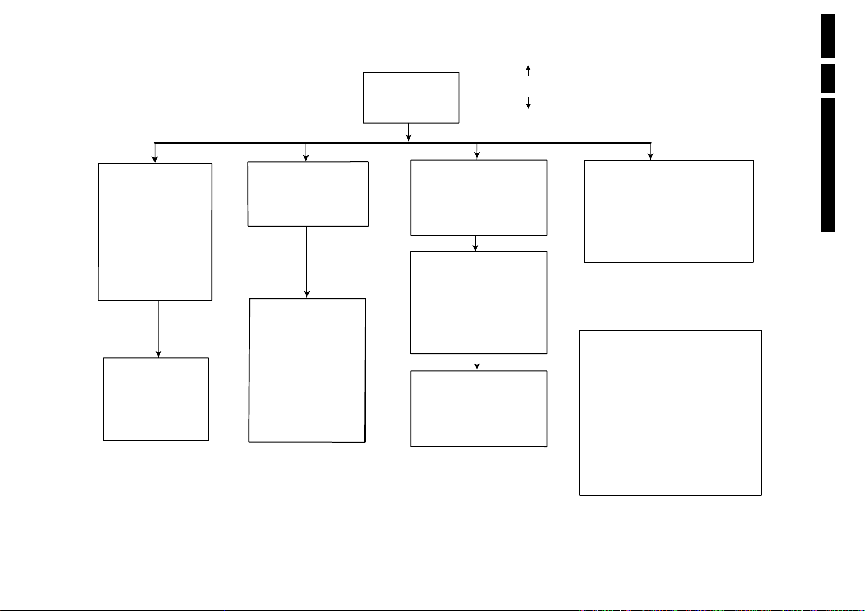
DISMANTLING INSTRUCTIONS
See exploded view for item numbers
Cover 300
⇒
Remove 9 screws 298
⇒
Lift the cover
to remove
mounting
demounting
4.2 Dismantling Instructions
EN 48 DVDR70 & DVDR75/0x14.
Figure 4-11
Front assy
⇒
⇒
⇒
⇒
Display board 1004
⇒⇒Remove screws
⇒
TR 06003_001
300103
open the tray and remove
tray front 70
remove 3 screws 205
(front assy
unlock the front from the
frame by releasing 2 snaps
on left and right
remove 9 screws 200 to
remove the plate front 102
→
frame 100)
→
(board
demount the board
front)
Remove screws 209
of DV input cable
the
200
IOE board 1005
⇒
Remove 2 screws 234, 235
→
(IOE board
demount the board
⇒
Analog board 1001
⇒
Remove the connections
⇒ remove 11 screws 230, 231
(board backplate)
⇒ remove 3 screws 250
(frame backplate)
⇒ remove 4 screws 210
(board frame)
⇒
remove screw safety
holder 145
⇒
demount the board
frame 100)
→
→
→
EPG board 1006
⇒
Remove 2 screws 218
(Digital board bracket 161)
⇒
Release the snaps of 2 spacers 130
(DVIO board EPG board)
⇒
demount the board.
DVIO board 1003
⇒
Remove 2 screws 216
(DVIO board bracket 161)
⇒
Release the snaps of 2 spacers 125
(DVIO board Digital board)
demount the board carefully.
⇒
(board to board connection to
the Digital board)
Digital board 1002
⇒
Remove the connections
⇒
Remove 4 screws 214
(Digital board frame 100)
demount the board.
⇒
→
→
→
→
→
DVDR BASIC ENGINE 1007
⇒ Remove the connections
⇒
Open the tray and remove
the tray front 70
⇒
Remove 4 screws 255
(Basic Engine 1007
⇒
Demount the DVDR Basic Engine
Manual opening of tray and removal of
tray front 70
In case the loader is defective and cannot be
opened electrically, you can open the tray
as follows:
It is possible to unlock the tray by means
⇒
of a screwdriver via a slot in the
front and frame at the underside.
.
Push the white pin of the slider at the
underside of the basic engine to the right
(seen from the front)
⇒
Open the unlocked tray.
→
support bracket 160)
Mechanical Instructions
Page 49
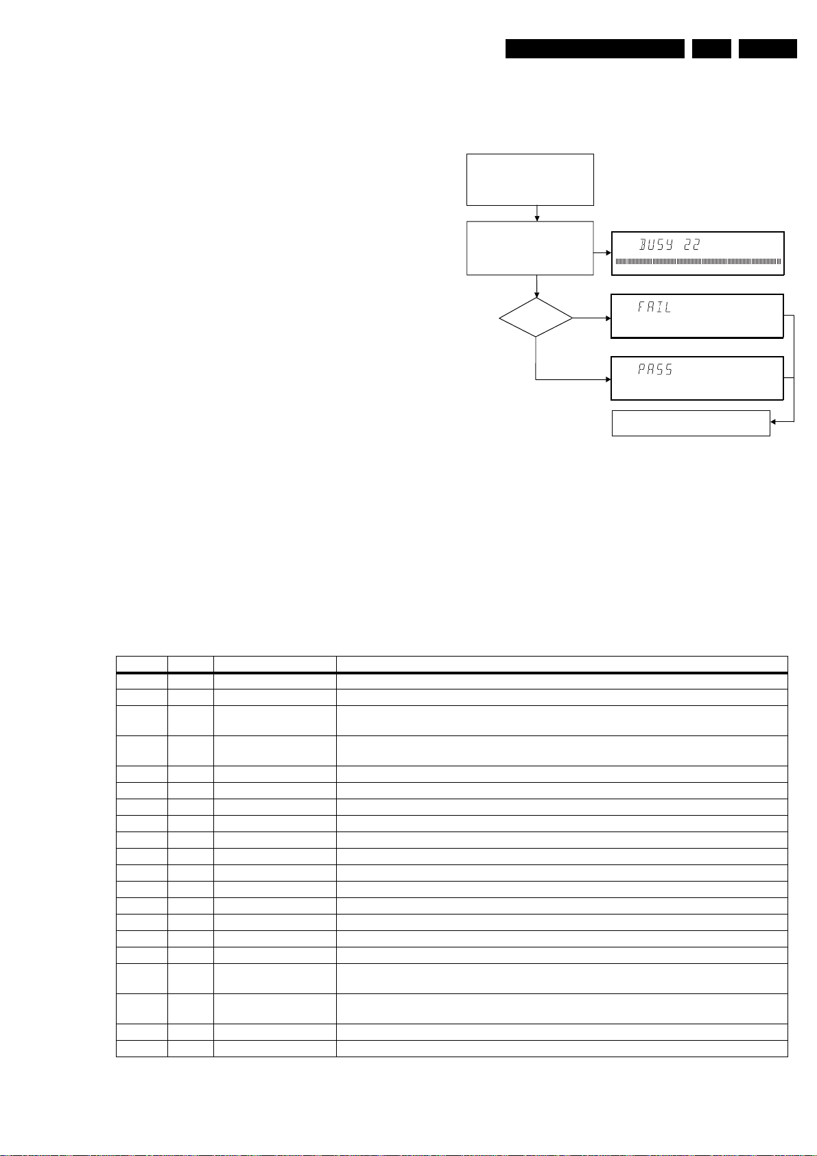
5. Diagnostic Software
Diagnostic Software
EN 49DVDR70 & DVDR75/0x1 5.
Due to the complexity of the DVD recorder, the time to find a
defect in the recorder can become long. To reduce this time,
the recorder has been equipped with Diagnostic and Service
software (DS). The DS offers functionality to diagnose the
DVDR hardware and tests the following:
• Interconnections between components
• Accessibility of components
• Functionality of the audio and video paths
This functionality can be accessed via several interfaces:
1. End user/Dealer script interface
2. Command Interface
3. Player script interface for sets with Digital Board 1.5,
Empress
4. Menu interface for sets with Digital Board 1.5, Empress
5.1 End User/Dealer Script Interface
5.1.1 Description
The End user/Dealer script interface gives a diagnosis on a
stand alone DVD recorder. During this mode, a number of
hardware tests (nuclei) are automatically executed to check if
the recorder is faulty. The diagnosis is simply a "fail" or "pass"
message. If the message "FAIL" appears on the display, there
is apparently a failure in the recorder. If the message "PASS"
appears, the nuclei in this mode have been executed
successfully. There can be still a failure in the recorder
because the nuclei in this mode don't cover the complete
functionality of the recorder.
5.1.2 Structure
Unplug the power cord
Hold key <PLAY> pressed
while you plug the recorder
During the test, the following display
is shown: the counter counts down
from the number of nuclei to be run
before the test finishes. Example:
SET O.K.?
NO
YES
To exit DEALER SCRIPT, unplug the power cord
Figure 5-1
The End use/Dealer script executes all diagnostic nuclei that
do not need any user interaction and are meaningful on a
standalone DVD recorder.
CL 16532095_068.eps
150801
5.1.3 Contents for sets with Digital Board 1.5, Empress
The nuclei called in the End user/Dealer script are the
following:
Counter Nucleus Name Description
22 104 HostdSdramWrR checks all memory locations of the 4MB SDRAM
21 106 HostdDramWrR checks all the DRAM connected to the microprocessor of the digital board
20 123 HostdI2cNvram checks the data line (SDA) and the clock line (SCL) of the I2C bus between the host decoder
and NVRAM
19 202 SAA7118I2c checks the interface between the Host I2C controller and the AVENC SAA7118 Video Input
Processor
18 200 VideoEncI2c checks the interface between the host I2C controller and Empress SAA6752
17 207 AudioEncI2c checks the I2C connection between the host decoder and Empress SAA6752
16 204 AudioEncAccess tests the HIO8 interface lines between the host decoder and the audio encoder
15 203 AudioEncSramAccess checks the access of the SRAM by the audio encoder (address and data lines).
14 205 AudioEncSramWrR tests the SRAM connected to the audio encoder
13 206 AudioEncInterrupt tests the interrupt line between the host decoder and the audio encoder
12 300 VsmAccess checks whether the VSM interrupt controllers and DRAM are accessible
11 303 VsmInterrupt checks both interrupt lines between the VSM and the host decoder
10 302 VsmSdramWrR tests the entire SDRAM of the VSM
9 1400 Clock11_289MHz switches the A_CLK of the micro clock to 11.2896 MHz
8 1401 Clock12_288MHz switches the A_CLK of the micro clock to 12.288 MHz
7 601 BeS2Bengine checks the S2B interface with the Basic Engine by sending an echo command
6 500 DisplayEcho checks the interface between the host processor and the slave processor on the display
board
5 700 AnalogueEcho checks the interface between the host processor and the microprocessor on the analogue
board
4 711 AnalogueNvram checks the NVRAM on the analogue board
3 706 AnalogueTuner checks whether the tuner on the analogue board is accessible
Page 50
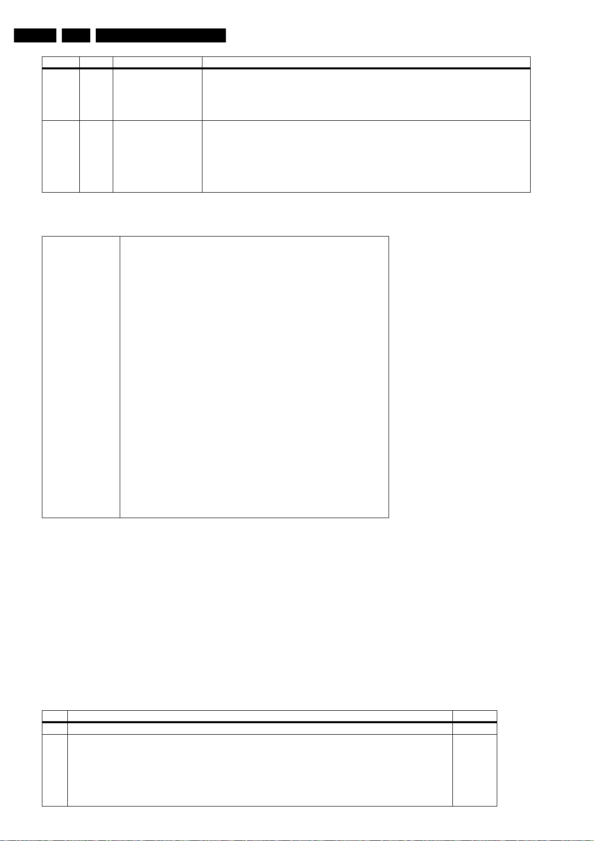
EN 50 DVDR70 & DVDR75/0x15.
Counter Nucleus Name Description
2 901 LoopAudioUserDealer This nucleus tests the components on the audio signal path The host decoder
- The analogue board
- The audio encoder
- The VSM
Attention: the rear cinch audio out has to be connected to the front cinch audio in.
1 906 LoopVideoUserDealer Nucleus for testing the components on the video signal system path:
- The VIP
- The video encoder
- The VSM
- The host decoder
- The analogue board
Attention: the rear cinch video out has to be connected to the front cinch video in.
5.1.4 Contents for sets with Digital Board Chrysalis
Diagnostic Software
Included tests: 1.DS_ANAB_COMMUNICATIONECHO_NUC
2.DS_DCB_COMMUNICATIONECHO_NUC
3. DS_BROM_COMMUNICATION_NUC
4. DS_SYS_SETTINGSDISPLAY_NUC
5. DS_CHR_DEVTYPEGET_NUC
6. DS_CHR_INT_PIC_NUC
7. DS_CHR_DMA_NUC
8. DS_BROM_WRITEREAD_NUC
9. DS_NVRAM_COMMUNICATION_NUC
10. DS_NVRAM_WRITEREAD_NUC
11. DS_SDRAM_WRITEREADFAST_NUC
12. DS_FLASH_WRITEREAD_NUC
13.DS_FLASH_CHECKSUMPROGRAM_NUC
14.DS_SYS_HARDWAREVERSIONGET_NUC
15. DS_VIP_DEVTYPEGET_NUC
16. DS_VIP_COMMUNICATION_NUC
17. DS_DVIO_LINKDEVTYPEGET_NUC
18. DS_DVIO_PHYDEVTYPEGET_NUC
19. DS_DVIO_LINKCOMMUNICATION_NUC
20. DS_DVIO_PHYCOMMUNICATION_NUC
21.DS_PSCAN_COMMUNICATIONDENC_NUC
22.DS_PSCAN_COMMUNICATIONDEINTERLACER_NUC
23. DS_BE_COMMUNICATIONECHO_NUC
24.DS_ANAB_COMMUNICATIONIICNVRAM_NUC
25.DS_ANAB_COMMUNICATIONIICTUNER_NUC
26.DS_ANAB_COMMUNICATIONIICSOUNDPROCESSOR_NUC
27.DS_ANAB_COMMUNICATIONIICAVSELECTOR_NUC
28. DS_ANAB_CHECKSUMPROGRAM_NUC
5.2 Player Script Interface only for sets with Digital Board 1.5 Empress
5.2.1 Description
The Player script will give the opportunity to perform a test that
will determine which of the DVD recorder's modules are faulty,
to read the error log and to perform an endurance loop test. To
successfully perform the tests, the DVD recorder must be
connected to a TV set.
To be able to check results of certain nuclei, the player script
expects some interaction of the user (i.e. to approve a test
picture or a test sound). Some nuclei (e.g. nuclei that test
functionality of the DVDR module) require that a DVD+RW disc
is inserted.
Only tests within the scope of the diagnostic software will be
executed hence only faults within this scope can be detected.
STEP DESCRIPTION NUCLEUS
1Press OPEN/CLOSE and PLAY at the same time and POWER ON the recorder to start the playerscript 2
2 The local display shows FPSEGMENTS. Press PLAY to start the test.
First the
last test is
lit.
Press PLAY to confirm that the correct pattern was lit (four times if the FPSEGMENTS test was successful).
Press RECORD to indicate that the correct pattern was not successfully lit.
Press STOP to skip this nucleus.
starburst pattern
light all segments
is lit, then the
test. After each of the 4 tests the user has to confirm that the correct pattern was
horizontal segments
5.2.2 Structure of the Player Script
The player script consists of a set of nuclei testing the hardware
modules in the DVD recorder: the Display PWB, the Digital
PWB, the Analogue In/Out PWB and the DVDR module.
Nuclei run by the player test need some user interaction; in the
next table this interaction is described. The player test is done
in two phases:
• Interactive tests: this part of the player test depends
strongly on user interaction and input to determine nucleus
results and to progress through the full test. Reading the
error log information can be useful to determine any errors
that occurred recently during normal operation of the DVD
player.
• The loop test will perform the same nuclei as the dealer
test, but it will loop through the list of nuclei indefinitely.
are lit, followed by the
vertical segments
and the
502
Page 51
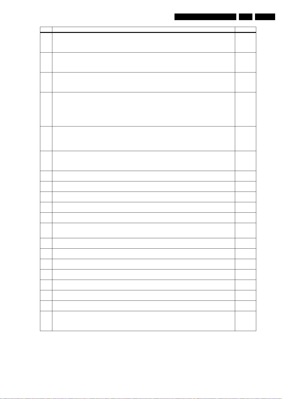
Diagnostic Software
STEP DESCRIPTION NUCLEUS
3 The local display shows FPLABELS. Press PLAY to start the test.
Press PLAY to confirm that all labels are lit.
Press RECORD to indicate that not all labels are lit.
Press STOP to skip this nucleus.
4 The local display shows FPLIGHT ALL. Press PLAY to start the test.
Press PLAY to confirm that everything was lit.
Press RECORD to indicate that not all patterns are lit.
Press STOP to skip this nucleus.
5 The local display shows FPLED. Press PLAY to start the test.
Press PLAY to confirm that the led is lit.
Press RECORD to indicate that the led is not lit.
Press STOP to skip this nucleus.
6 The local display shows FPKEYBOARD. Press PLAY to start the test.
Attention all keys have to be pressed to get a positive result!
Press PLAY for more than one second to confirm that all the keys were pressed and shown on the local display. If not all the keys were pressed, a FAIL message will appear on the local display.
Press RECORD for more than one second to indicate that not all keys were pressed and shown on the local
display.
Press STOP for more than one second to skip this nucleus.
7 The local display shows FPREMOTE CONTROL. Press PLAY to start the test.
Press PLAY to confirm that a key on the remote control was pressed and shown on the local display. Only
one key has to be pressed to get a successful result.
Press RECORD to indicate that the key on the remote control was pressed but not shown on the local display.
Press STOP to skip this nucleus.
8 The local display shows FPDIMMER. Press PLAY to start the test.
Press PLAY to confirm that the text on the local display was dimmed.
Press RECORD to indicate that the text on the local display was not dimmed.
Press STOP to skip this nucleus.
9 The local display shows ROUTE VIDEO. Press PLAY to start the test.
Press STOP to skip this nucleus.
10 The local display shows ROUTE AUDIO. Press PLAY to start the test.
Press STOP to skip this nucleus.
11 The local display shows COLOUR-BAR ON. Press PLAY to start the test.
Press STOP to skip this nucleus.
12 The local display shows PINK NOISE ON. Press PLAY to start the test.
Press STOP to skip this nucleus.
13 The local display shows PINK NOISE OFF. Press PLAY to start the test.
Press STOP to skip this nucleus.
14 The local display shows SINE ON. Press PLAY to start the test.
Press STOP to stop the sine.
Press STOP to skip this nucleus.
15 The local display shows COLOUR-BAR OFF. Press PLAY to start the test.
Press STOP to skip this nucleus.
16 The local display shows BERESET. Press PLAY to start the test.
Press STOP to skip this nucleus.
17 The local display shows BETRAY OPEN. Press PLAY to start the test.
Press STOP to skip this nucleus.
18 The local display shows BETRAY CLOSE. Press PLAY to start the test.
Press STOP to skip this nucleus.
19 The local display shows BEWRITE READ. Press PLAY to start the test.
Press STOP to skip this nucleus.
20 The local display shows BETRAY OPEN. Press PLAY to start the test.
Press STOP to skip this nucleus.
21 The local display shows BETRAY CLOSE. Press PLAY to start the test.
Press STOP to skip this nucleus.
22 The local display shows READ ERRORLOG. Press PLAY to start the test.
Press STOP to skip this nucleus.
If the player test succeeded, the user/dealer script will start in an endless loop.
If the player test failed, the local display will display FAIL and the error code
503
520
504
505
506
518
712
713
120
115
116
117
121
603
616
615
617
616
615
633
EN 51DVDR70 & DVDR75/0x1 5.
Remark
In case of failure, the display shows " FAIL XXXXXX ". The
description of the shown error code can be retrieved in the
survey of Nuclei Error Codes (paragraph 5.4). Once an error
occurs, it is not possible to continue the player script. Unplug
the set and restart the player script. By pressing the STOP key,
it is possible to jump over the failure and to continue the player
script.
Page 52
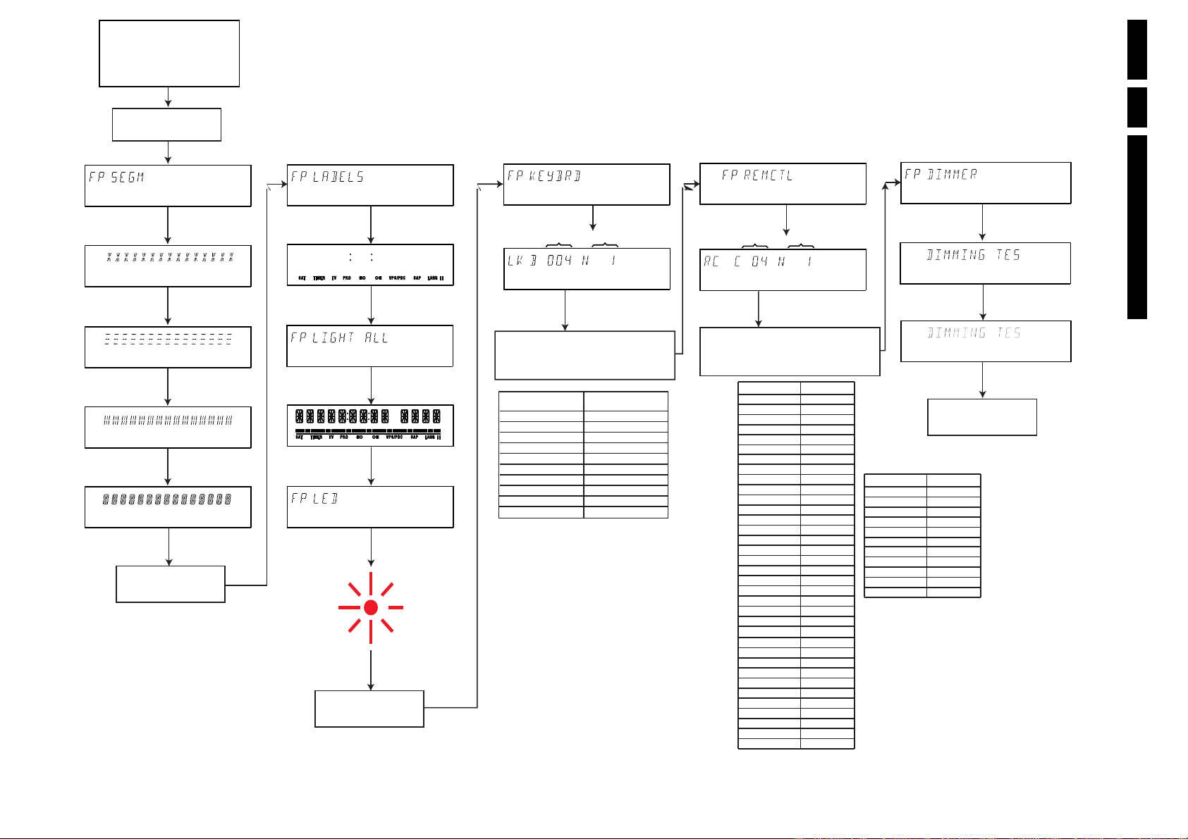
Figure 5-2
Unplug the power cord
Hold 2 keys
<OPEN/CLOSE>
simultaneously pressed while
you plug the recorder
+ <PLAY>
FRONT PANEL TEST
PRESS
<PLAY>
TO START TEST
PRESS
<PLAY>
IF OK
<RECORD>
PRESS
TR 01006_003
270103
<STOP>
PRESS
TO SKIP TEST
PRESS
<PLAY>
<STOP>
PRESS
PRESS
<PLAY>
<STOP>
PRESS
PRESS
<PLAY>
<STOP>
PRESS
IF NOT OK
IF OK
TO ABORT
IF OK
TO ABORT
IF OK
TO ABORT
PRESS
<PLAY>
TO START TEST
PRESS
<PLAY>
TO START TEST
PRESS
<PLAY>
TO START TEST
PRESS
PRESS
<PLAY>
IF OK
<RECORD>
PRESS
<STOP>
TO SKIP TEST
<PLAY>
PRESS
<RECORD>
PRESS
PRESS
<STOP>
TO SKIP TEST
PRESS
<PLAY>
IF OK
<RECORD>
PRESS
PRESS
<STOP>
TO SKIP TEST
LED BECOMES RED
IF NOT OK
IF OK
IF NOT OK
IF NOT OK
PRESS
<PLAY>
TO START TEST
HEXADECIMAL
KEY CODE
<PLAY>
PRESS
PRESS
MORE THAN 1S IF TEST IS OK
<RECORD>
FRONT KEY NAME
STANDBY/ON
OPEN/CLOSE
STOP
PLAY
RECORD
SEARCH <<
SEARCH >>
CHANNEL UP
CHANNEL DOWN
REC MODE
<STOP>
PRESS
TO SKIP TEST
XX TIMES
PRESSED
PRESS ALL KEYS AT LEAST ONCE
SEE TABLE FOR KEY CODES
MORE THAN 1S IF TEST IS NOT OK
FRONT KEY CODE
00E
001
002
003
004
006
005
009
00A
00D
PRESS
PRESS
<PLAY>
TO START TEST
HEXADECIMAL
RC KEY CODE
PRESS AT LEAST ONE KEY
ON THE REMOTE CONTROL
SEE TABLE FOR RC KEY CODES
TO EXIT TEST: PRESS ONE OF FOLLOWING KEYS
ON THE LOCAL KEYBOARD
<PLAY>
PRESS
PRESS
IF TEST IS OK
<RECORD>
RC KEY NAME
TV/DVD
STANDBY
STOP
REC/OTR
PLAY
PREVIOUS
GUIDE
NEXT
DISC
SYSTEM
UP
LEFT
RIGHT
DOWN
RETURN
OK
CLEAR
TIMER
SELECT
VOL +
VOL -
REC MODE
DIM
1
2
3
4
5
6
7
8
9
0
T/C
MONITOR
IF TEST IS NOT OK
TO SKIP TEST
XX TIMES
PRESSED
RC KEY CODE
43
0C
31
37
2C
21
CC
20
54
0F
58
5A
5B
59
83
5C
41
FE
FA
ONLY FOR TV
ONLY FOR TV
94
13
01
02
03
04
05
06
07
08
09
00
C8
EE
<STOP>
RC KEY NAME
PLAY MODE
REC MODE
DISC MANAGER
FSS
i
SUBTITLE
AUDIO
ANGLE
ZOOM
SLOW
PAUSE
PRESS
<PLAY>
TO START TEST
DIGITAL BOARD TEST
RC KEY CODE
1D
94
C7
CF
CB
4B
4E
85
F7
22
30
<STOP>
PRESS
TO SKIP TEST
<PLAY>
PRESS
<RECORD>
PRESS
IF OK
IF NOT OK
EN 52 DVDR70 & DVDR75/0x15.
Diagnostic Software
Page 53
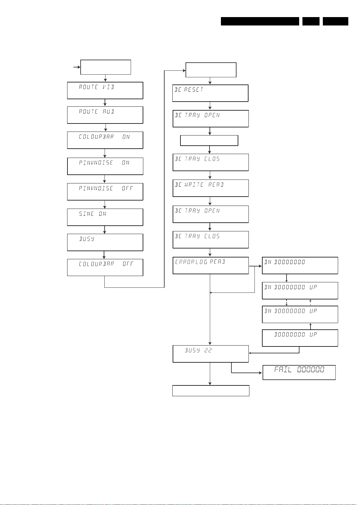
Diagnostic Software
EN 53DVDR70 & DVDR75/0x1 5.
FRONTPANEL
TEST
DIGITAL BOARD &
ANALOG BOARD
TEST
press
<PLAY>
< STOP >
press
press
<PLAY>
< STOP >
press
<PLAY>
press
< STOP >
press
press
<PLAY>
< STOP >
press
press
<PLAY>
<NEXT >
press
press
<PLAY>
< STOP >
press
to execute
to skip
to execute
to skip
to execute
to skip
to execute
to skip
to execute
to skip
to execute
to skip
BASIC ENGINE
TEST
press
<PLAY>
<NEXT >
press
press
<PLAY>
<STOP>
INSERT DVD +RW DISC TO EXECUTE
WRITE / READ TEST
press
press
press
press
press
press
press
<PLAY>
<STOP>
<PLAY>
<STOP >
<PLAY>
<STOP>
to execute
to skip
to execute
to skip
to execute
to skip
to execute
to skip
to execute
to skip
press
press
<STOP>
<PLAY>
to continue
to execute
press
<PLAY>
to execute
<STOP>
press
press
to skip
<STOP>
to skip
NO ERRORS LOGGED
IF ERROR
To exit PLAYER SCRIPT, unplug the power cord
<PLAY>
<STOP>
PRESS
TO STEP DOWN
<STOP>
PRESS
TO STEP DOWN
PRESS
TO STEP UP
PRESS
TO STEP UP
PRESS
<PLAY>
TR 01007_003
270103
<RECORD>
<RECORD>
TO CONTINUE
Figure 5-3
Page 54
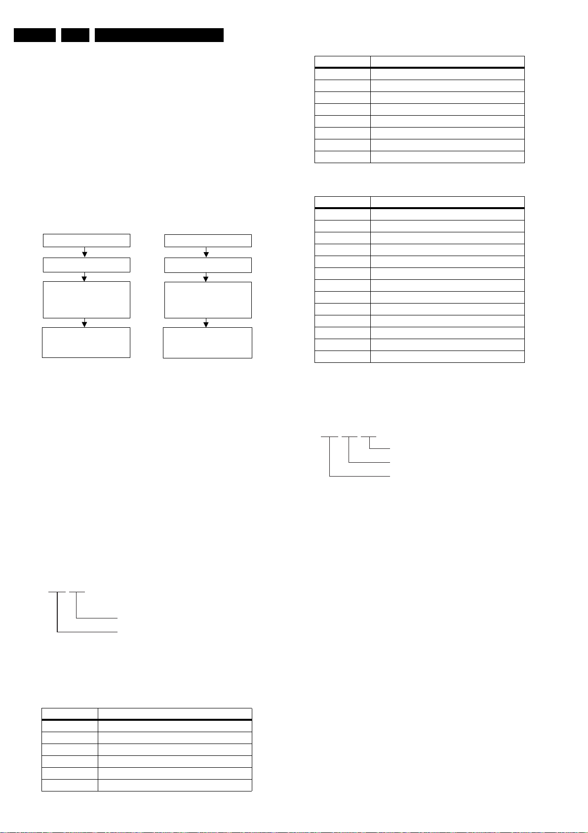
EN 54 DVDR70 & DVDR75/0x15.
Diagnostic Software
5.2.3 Error Log
Explanation:
The application errors will be logged in the NVRAM. The
maximum number of error bytes that will be visible is 19. The
last reported error is shown as DN D0000000, the oldest visible
error as D0000000 UP and the errors in between as DN
D0000000 UP. DN stands for DOWN, UP stands for
UPWARDS. The shown error codes are identical to the Nuclei
Error Codes (paragraph 5.4).
5.2.4 Trade Mode
TRADE MODE
When the recorder is in Trade Mode, the recorder cannot be
controlled by means of the front key buttons, but only by means
of the remote control.
IF TRADE MODE OFF
UNPLUG THE RECORDER
PRESS 2 KEYS
SIMULTANEOUSLY
<STOP> + <OPEN/CLOSE>
PLUG THE RECORDER
RECORDER IS IN TRADE MODE
WHEN PRESSING FRONT
KEYS, THE RECORDER
DOESN'T RESPOND
IF TRADE MODE ON
UNPLUG THE RECORDER
PRESS 2 KEYS
SIMULTANEOUSLY
<STOP> + <OPEN/CLOSE>
PLUG THE RECORDER
RECORDER IS IN NORMAL MODE
WHEN PRESSING FRONT
KEYS, THE RECORDER
WILL RESPOND
Figure 5-4
5.2.5 Virgin mode
CL 16532095_071.eps
150801
Group number Group name
6 Basic Engine
7 Analogue board (DVDR only)
8 DVIO (DVDR only)
9 Loop nuclei (DVDR only)
10 Library sub nuclei (I2C nuclei)
11 User interface
12 Furore (SACD only)
13 DAC (SACD only)
The following groups are defined for Digital Board Chrysalis:
Group number Group name
0 Basic / Scripts
1 Chrysalis
2 Boot EEPROM
3 NVRAM
4 SDRAM
5Flash
6 Video Input Processor
7DVIO
8 Progressive Scan
9 Basic Engine
10 Display and Control Board
11 Analogue Board
12 System
5.3.2 Error Handling
Each nucleus returns an error code. This code contains six
numerals, which means:
If you want that the recorder starts up in Virgin mode, follow this
procedure:
• Unplug the recorder
• plug the recorder again while you keep the STAND BY/ON
key pressed
• the set starts up in Virgin mode.
5.3 Menu and Command Mode Interface
5.3.1 Nuclei Numeration
Each nucleus has a unique number of four digits. This number
is the input of the command mode.
[ XX YY ]
Nucleus number
Nucleus group number
Figure 5-5
The following groups are defined for Digital Board 1.5,
Empress:
Group number Group name
0 Basic / Scripts
1 Host decoder (Sti5505 and memory)
2 Audio / video encoder (DVDR only)
3 VSM (DVDR only)
4 NVRAM
5 Front Panel
CL 06532152_012.eps
051200
[ XX YY ZZ ]
Error code
Nucleus number
Nucleus group number
Figure 5-6
The nucleus group numbers and nucleus numbers are the
same as above.
5.3.3 Command Mode Interface
Set-Up Physical Interface Components
Hardware required:
• Service PC
• one free COM port on the Service PC
• special cable to connect DVD recorder to Service PC
The service PC must have a terminal emulation program (e.g.
Hyperterminal) installed and must have a free COM port (e.g.
COM1). Activate the terminal emulation program and check
that the port settings for the free COM port are: 19200 bps, 8
data bits, no parity, 1 stop bit and no flow control. The free COM
port must be connected via a special cable to the RS232 port
of the DVD recorder. This special cable will also connect the
test pin, which is available on the connector, to ground (i.e.
activate test pin).
Code number of PC interface cable: 3122 785 90017
Activation Digital Board 1.5 Empress
Plug the recorder to the mains and the following text will appear
on the screen of the terminal (program):
CL 06532152_013.eps
051200
Page 55
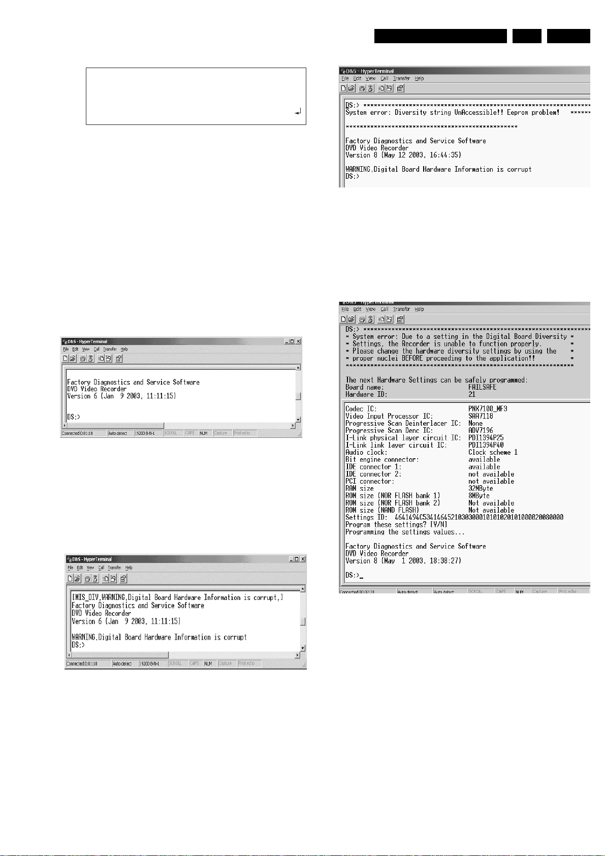
Diagnostic Software
DVD Video Recorder Diagnostic Software version 48
Basic SDRAM Data bus test passed
Basic SDRAM Address bus test passed
Basic SDRAM Device test passed
(M) enu, (C) ommand or (S) 2B-interface? [M] : @ C
DD:>
Figure 5-7
The first line indicates that the Diagnostic software has been
activated and contains the version number. The next lines are
the successful result of the SDRAM interconnection test and
the basic SDRAM test. The last line allows the user to choose
between the three possible interface forms. If pressing C has
made a choice for Command Interface, the prompt ("DD>") will
appear. The diagnostic software is now ready to receive
commands. The commands that can be given are the numbers
of the nuclei.
CL 16532095_073.eps
150801
EN 55DVDR70 & DVDR75/0x1 5.
Error messages D&S program
Figure 5-9b
In these cases, the boot EEPROM of the Chrysalis Digital
Board does not contain the required string with the hardware
information. To update the Digital Board with the correct string,
nucleus 1226 must be executed.
Activation Digital Board Chrysalis
1. Pull the mains cord from the recorder and reconnect it
again (reboot).
2. The next welcome message will appear on the PC:
Welcome screen D&S program
Figure 5-8
Now, the prompt 'DS:>' will appear. The diagnostic software is
now ready to receive commands. The commands that can be
given are the numbers of the nuclei. If you see above shown
screen, continue with paragraph 'Nuclei Codes'.
3. It is possible that the next messages will appear when
starting the DVD+RW for the first time
Error messages D&S program
See next section 'Diversity String Input'.
There can also be the next error message.
Figure 5-9a
Figure 5-9c
Enter "Y" to program a safe string. With this automatically
generated string the board will work in principle but it has to be
checked if all board settings were detected correctly.
Page 56
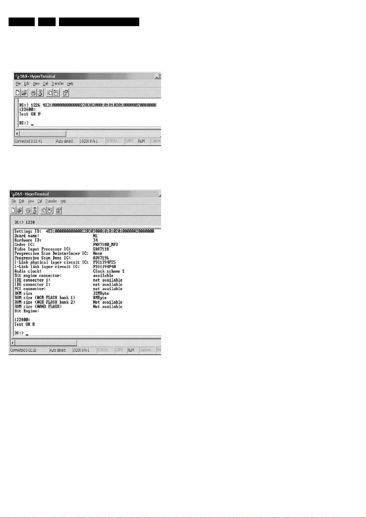
EN 56 DVDR70 & DVDR75/0x15.
Diversity String Input
4. Execute nucleus 1226 to enter the string. Please see
chapter 8.5 for details
Nucleus 1226 execution with string
Figure 5-10
5. To check if the hardware info is filled correctly, you can
execute nucleus 1228.
Nucleus 1228 info example
Diagnostic Software
Figure 5-11
6. Exit the 'Terminal' program.
7. Reboot the DVD recorder to allow the software to start.
Page 57
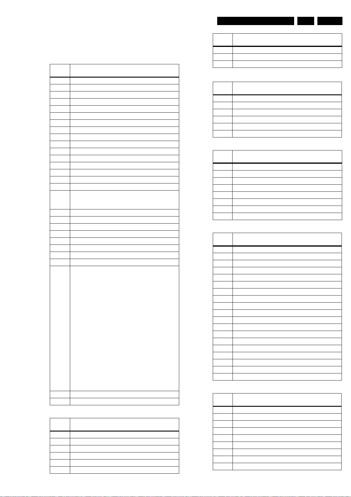
Diagnostic Software
EN 57DVDR70 & DVDR75/0x1 5.
Command Overview Digital Board 1.5 Empress
We provide an overview of the nuclei and their numbers. This
overview is preliminary and subject to modifications.
Host Decoder [01]
[xx yy]
Number
100 Checksum Flash
101 Flash Write Access 1
102 Flash Write Access 2
103 Flash Write Read
104 SdRam Write Read
105 SdRam Write Read Fast
106 Dram Write Read
107 Dram Write Read Fast
108 Hardware Version
109 Mute On
110 Mute Off
115 Pink Noise On
116 Pink Noise Off
117 Sine On
118 Sine Burst 1kHz
119 Sine Burst 12kHz
120 Colour-bar On
121 Colour-bar Off
122 NvramWrR
123 NvramI2c
130 Boot Version
131 Application Version
132 Diagnostics Version
133 Download Version
134 Write / read I2C message to / from digital board
135 Video Test Signal
136 Video Test Signal Off
137 Macrovision Off
Audio Video Decoder [02]
[xx yy]
Number
200 Video Encoder I2C
202 SAA7118 I2C
203 Audio Encoder SRAM Access
204 Audio Encoder Access
205 Audio Encoder SRAM Write Read
206 Audio Encoder Interrupts
Nuclei
Note: Use nuclus 712 with parameter 07 to route the
signals to the analogue board output
OnNote: Use nuclus 712 with parameter 07 to route
the signals to the analogue board output.
Input: 135 [a] [b]
a: Number of test image,
0. Horizontal colour-bar
1. White
2. Yellow
3. Light blue
4. Green
5. Magenta
6. Red
7. Blue
8. Black
9. Colour triangle (execution time is 12 seconds)
10. Test image for progressive scan (execution time
is 6 seconds)
b: Video standard,
0. PAL BDGHI
1. NTSC
Nuclei
[xx yy]
Number
207 Audio Encoder I2C
208 SAA7118 select input
209 Empress Version
VSM [03]
[xx yy]
Number
300 Register Access
301 SDRAM Access
302 SDRAM Write Read
303 Interrupt lines
304 VSM Interconnection
305 UART
NVRAM [04]
[xx yy]
Number
400 Reset
401 Read
402 Modify
403 UniqueNr Read
404 Read Error Log
407 Reset Error Log
409 Line2 Region-Code Reset
410 UniqueNr Store
Front Panel [05]
[xx yy]
Number
500 Echo
501 Version
502 Segment
503 Label
504 Led
505 Keyboard
506 Remote-Control
507 Segment Starburst
508 Segment Vertical
509 Segment Horizontal
514 Beeper
515 Discbar
516 Discbar Dots
517 Vu / Grid
518 Dimmer
519 Blinking
520 Light All Segments
522 Flap Open
523 Flap Close
Basic Engine [06]
[xx yy]
Number
600 S2B Pass
601 S2B Echo
602 Version
603 Reset
604 Focus On
605 Focus Off
606 Disc Motor On
607 Disc Motor Off
608 Radial On
Nuclei
Nuclei
Nuclei
Nuclei
Nuclei
Page 58
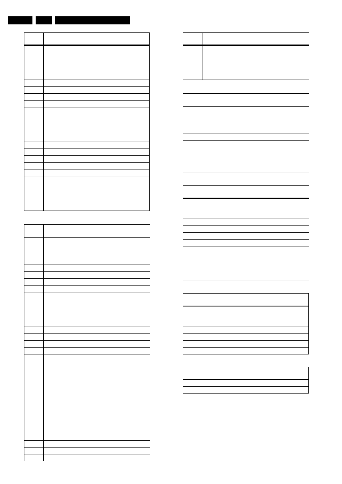
EN 58 DVDR70 & DVDR75/0x15.
Diagnostic Software
[xx yy]
Number
609 Radial Off
615 Tray In
616 Tray Out
617 Write Read
618 Write Read Endless Loop
619 Selftest
620 BE Test
621 Laser Test
622 Spindle (Disc) Motor Test
623 Focus Test
624 Sledge Motor Test
625 Sledge Motor Slow
626 Tilt
627 EEPROM Read
628 EEPROM Write
629 Optimise Jitter
630 Radial ATLS Calibration
631 Get Statistics Information
632 Reset Statistics Information
633 BE Read Error Log
634 BE Reset Error Log
638 Get Self Test Result
639 Radial Initialisation
640 Get OPU info
Analog Board [07]
[xx yy]
Number
700 Echo
703 Boot Version
704 Hardware Version
705 Clock Adjust
706 Tuner
707 Frequency Download
708 Data Slicer
709 Sound Processor
710 AV Selector
711 Nvram
712 Route Video
713 Route Audio
715 Set Slash Version
716 Application Version
717 Diagnostics Version
718 Download Version
720 Bargraph Level Adjustment
721 Clock correction
722 Clock reference
723 Re-virginise Recorder
724 Flash Checksum
725 Tuner frequency selection
727 Set virgin bit
728 Clear Virgin Bit
729 Write / read I2C message to / from analogue board
Nuclei
Nuclei
Europe: To make video and audio signals from the
tuner available on Scart2, send command "712 08".
For Nafta/Apac: To make the black/white Video
available on Y/C Rear Out connector, send
command “712 08”
Input: 725 [frequency in MHz*16] [system]
System: NTSC=16, PAL BG=16, PAL I=32, PAL
DK=48, SEC L=64, SEC LS=80, SEC BG=96, SEC
DK=112
[xx yy]
Number
730 Store external presets
731 Get slash version
732 AFC Reference Voltage Tuner
736 Get EPG Version
737 Get operating hours in Tuner Mode
DVIO [08]
[xx yy]
Number
800 Check DVIO board presence
801 Reset DVIO
802 DVIO Access
803 Get DVIO error codes
804 Get DVIO module Ids
805 Execute DVIO module SelfTestInput: 805 [a]
806 Set DVIO led on.
807 Set DVIO led off.
Loop Nuclei [09]
[xx yy]
Number
900 Digital Audio Loop(no function in Gen. 1.5 and Lead)
901 User / Dealer Audio Loop
902 Digital Video Loop
903 Digital Video VBI Loop
904 System Video Loop
905 System Video VBI Loop
906 User / Dealer Video Loop
907 User / Dealer Video VBI Loop
908 System Audio Loop SCART
909 System Audio Loop CINCH
910 Digital DVIO Video Loop
911 System Video Vip
Miscellanious [14]
[xx yy]
Number
1400 Clock 11.289 MHz
1401 Clock 12.288 MHz
1412 Progressive Scan I2C
1413 Progressive Scan test image on
1414 Progressive Scan test image off
1415 Progressive Scan Route Enable
1416 Progressive Scan Route Disable
Scripts [00]
[xx yy]
Number
1 UserDealer Script
2 Player Script
Nuclei
Nuclei
[b]Parameters: a=1/0…full Ram test, b=1/0…cable
connected
Nuclei
Nuclei
Nuclei
Routing Audio and Video
Route Video
Nucleus Number: 712
Description
This nucleus routes the video signals on the analogue board to
the destination determined by the input parameters
Page 59
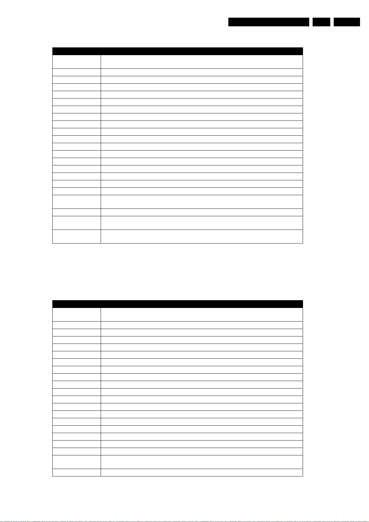
Diagnostic Software
The paths that are available for video routing and their description (Euro region):
Path ID Description
00 Input signal is VIDEO(CVBS) from digital board and will be re-routed back to the digital
board.
01 Input signal is from FRONT VIDEO(CVBS) IN and will be routed to the digital board.
02 No Routing.
03 Input signal is from FRONT S-VIDEO(Y/C) and will be routed to the digital board.
04 No Routing.
05 Input signal is CVBS from SCART1 and will be routed to the digital board.
06 Input signal is CVBS from SCART2 and will be routed to the digital board.
07 Input Signal is CVBS from Digital Board and it will be routed to Scart1 and Scart2.
08 Input signal is VIDEO(CVBS) from ANTENNA IN and will be routed to SCART2.
09 Input signal is VIDEO(CVBS) from SCART1 and will be routed to SCART2.
10 Input signal is VIDEO(CVBS) from SCART2 and will be routed to SCART1.
11 Signal path is routed Fast Blank from Scart2 pin16 and will be routed Scart1 pin16
12 Input Signal is YC from Digital Board and it will be routed to Scart1.
13
14 No Routing.
15 Input Signal is CVBS from TUNER and it will be routed to Digital .
16 No Routing.
17 Input Signal is routed from digital board YC to REAR S-VIDEO(YC) OUT
18 Signal path is routed from digital board RGB to RGB SCART1 and from digital board CVBS
to digital board CVBS.
19 No Routing.
20 Input RGB Signal is routed from Digital Board to SCART1(RGB),Input CVBS Signal from
Digital Board to Digital Board and Fast Blanking Signal from Scart 2 to Scart1.
21 Input Y/C Signal from Digital Board is routed to Rear Y/C Connector and Input Y/c Signal
from Front Y/C connector is routed to Digital Board.
EN 59DVDR70 & DVDR75/0x1 5.
Example
DD:> 712 01
71200: Video routing on the Analogue Board OK.
Test OK @
Path ID Description
00 Input signal is from FRONT AUDIO IN and will be routed to the digital board.(This is done so
that nucleus 901 works)
01 Input signal is from FRONT AUDIO IN and will be routed to the digital board.
02 No Routing.
03 Input signal is AUDIO from SCART1 and will be routed to the digital board.
04 Input signal is AUDIO from SCART2 and will be routed to the digital board.
05 No routing.
06 No routing.
07 Input Audio signal is from the digital Board and it will be routed to the Scart 1 and Scart2
08 Input AUDIO signal from TUNER and will be routed to SCART2.
09 Input signal is AUDIO from SCART1 and will be routed to SCART2.
10 Input audio signal from Scart2 is routed to Scart1.
11 Input Audio signal is routed from DVIO to Scart2.
12
13 No Routing.
14 Input is Audio Signal from DVIO and it will be routed to Digital Board.
15 Input is Audio Signal from TUNER and it will be routed to Digital Board..
16 No routing.
17 No Routing.
18 Input signal is from FRONT AUDIO IN and will be routed to SCART2.
21 Input signal is from FRONT AUDIO IN and will be routed to the digital board.(This is done so
that nucleus 909.1 works)
Route Audio
Nucleus Number: 713
Description
This nucleus routes the audio on the analogue board to the
destination determined by the input parameters
The paths that are available for audio routing and their
description (Europe version)
EXAMPLE DD:> 713 00
71300: Audio routing on the Analogue Board OK.
Page 60
EN 60 DVDR70 & DVDR75/0x15.
Diagnostic Software
Test OK @
Command overview Digital Board Chrysalis
Below you will find an overview of the nuclei, their numbers,
and their error codes. This overview is preliminary and subject
to modifications.
Chrysalis (CHR)
Nucleus Name DS_CHR_DevTypeGet
Nucleus Number 100
Description Sends the device ID and the module ids and revisions of the PNX7100 (Chrysalis) to the
User Input None
Example DS:> 100
stdout port.
Device ID 7100
Codec ID PNX7100_MF2
F-BCU (0x0102) 1.0 INTC (0x011d) 1.0 PCI-XIO(0x0113) 1.0
SIF(0x013b) 1.0 EJTAG (0x0104) 0.0 S-BCU (0x0102) 1.0
BOOT (0x010a) 1.0 CONFIG (0x013f) 1.0 RESET (0x0123) 1.0
DEBUG (0x0116) 0.0 UART0 (0x0107) 0.1 UART1 (0x0107) 0.1
UART2 (0x0107) 0.1 UART3 (0x0107) 0.1 I2C0 (0x0105) 0.1
I2C1 (0x0105) 0.1 GPIO (0x013c) 1.0 SYNC (0x013a) 1.0
DISP0 (0xa015) 0.1 DISP1 (0xa00f) 0.0 OSD (0x0136) 0.1
SPU (0xa00e) 0.0 MIXER (0x0137) 1.0 DENC (0x0138) 0.1
CCIR (0x0139) 1.0 VDEC (0x0133) 0.1 PARSER (0xa00d) 0.0
DV (0xa00c) 0.0 BEI (0xa00a) 0.0 IDE (0xa009) 0.0
SGDX (0xa008)0.0 BYTE (0xa00b) 0.0 OUTPUT (0xa003) 0.0
ACOMP (0xa000) 0.0 VFE (0xa001) 0.0 VCOMP (0xa002) 0.0
SCR (0x0000) 0.0 SIFF (0xa011) 0.0 WMD (0xa010) 0.0
AUDIO0 (0xa015) 0.1 AUDIO1 (0xa00f) 0.0 PSCAN (0xa018) 0.0
010000:
Test OK @
Nucleus Name DS_CHR_TestImageOn
Nucleus Number 101
Description Generates a test-image of a selected video standard on selected video output on the digital
User Input The user has to decide which test image, video standard and video output must be used:
Example DS:> 101
board. When no input is given, the default values will be used. Use nucleus
DS_ANAB_VideoRouting to route the video signal on the analogue board output
Test image id:
0 VERTICAL_COLOURBAR (default)
1 HORIZONTAL_COLOURBAR
2 WHITE
3 YELLOW
4 CYAN
5 GREEN
6 MAGENTA
7 RED
8 BLUE
9 BLACK
10 GRAY
Video standard:
PAL (default)
NTSC
Video output:
ALL CVBS and YC and RGB (default)
CVBS
YC
RGB
YUV
PSCAN progressive scan
010100:
Test OK @
DS:> 101 0 pal cvbs
010100:
Test OK @
DS:> 101 4 ntsc yc
010100:
Test OK @
Page 61
Diagnostic Software
Nucleus Name DS_CHR_TestImageOff
Nucleus Number 102
Description Switches the test-image off.
User Input None
Example DS:> 102
010200:
Test OK @
Nucleus Name DS_CHR_SineOn
Nucleus Number 103
Description Generate an audio sine signal on the audio output of the digital board.
Note: Left channel 6kHz, right channel 12 kHz sine. Make sure to route the signal first.
User Input None
Example DS:> 103
010300:
Test OK @
Nucleus Name DS_CHR_SineOff
Nucleus Number 104
Description Stop generating the audio sine signal
User Input None
Example DS:> 104
010400:
Test OK @
EN 61DVDR70 & DVDR75/0x1 5.
Nucleus Name DS_CHR_SineBurst
Nucleus Number 105
Description Generate an audio sine signal on the audio output of the digital board for 4 seconds.
Note: Left channel 6kHz, right channel 12 kHz sine with some known hick-ups
User Input None
Example DS:> 105
010500:
Test OK @
Nucleus Name DS_CHR_MuteOn
Nucleus Number 106
Description Mute the audio outputs of the digital board
User Input None
Example DS:> 106
010600:
Test OK @
Nucleus Name DS_CHR_MuteOff
Nucleus Number 107
Description De-mute the audio outputs of the digital board
User Input None
Example DS:> 107
010700:
Test OK @
Nucleus Name DS_CHR_DvLedOn
Nucleus Number 108
Description Check the connection to the DV-LED on the digital board by switching it on
User Input None
Example DS:> 108
010800:
Test OK @
Nucleus Name DS_CHR_DvLedOff
Nucleus Number 109
Description Switch off the DV-LED on the digital board
User Input None
Page 62
EN 62 DVDR70 & DVDR75/0x15.
Diagnostic Software
Example DS:> 109
Nucleus Name DS_CHR_MacroVisionOn
Nucleus Number 110
Description Turn on MacroVision.
User Input None
Example DS:> 110
Nucleus Name DS_CHR_MacroVisionOff
Nucleus Number 111
Description Turn off MacroVision.
User Input None
Example DS:> 111
Nucleus Name DS_CHR_Peek
Nucleus Number 112
Description Peek a value on a specified address
User Input The address to peek on
Example DS:> 112 0xa0700000
010900:
Test OK @
011000:
Test OK @
011100:
Test OK @
011200: Value read = 0x000001BD
Test OK @
Nucleus Name DS_CHR_Poke
Nucleus Number 113
Description Poke a value on a specified address
User Input The address to poke and the value: <address><value>
Example DS:> 113 0xa0700000 0xaabbccdd
Nucleus Name DS_CHR_INT_PICInterrupts
Nucleus Number 114
Description Test all interrupts of the priority interrupt controller
User Input Example DS:> 114
Nucleus Name DS_CHR_DMA_TestDMA
Nucleus Number 115
Description Test the memory to memory DMA transfer
User Input Example DS:> 115
011300:
Test OK @
011400:
Test OK @
011500:
Test OK @
Boot EEPROM (BROM)
Nucleus Name DS_BROM_Communication
Nucleus Number 200
Description Check the communication between the IIC controller of the Chrysalis and the boot EE-
User Input None
Example DS:> 200
PROM
020000:
Test OK @
Nucleus Name DS_BROM_WriteRead
Nucleus Number 201
Page 63
Diagnostic Software
Description Check whether the Boot EEPROM can be written to and read from
User Input None
Example DS:> 201
020100:
Test OK @
NVRAM
Nucleus Name DS_NVRAM_Communication
Nucleus Number 300
Description Check the communication between the IIC controller of the Chrysalis and the EEPROM
User Input None
Example DS:> 300
030000:
Test OK @
Nucleus Name DS_NVRAM_WriteRead
Nucleus Number 301
Description Check whether the EEPROM can be written to and read from
User Input None
Example DS:> 301
030100:
Test OK @
EN 63DVDR70 & DVDR75/0x1 5.
Nucleus Name DS_NVRAM_Clear
Nucleus Number 302
Description Make the EEPROM empty, containing all zeroes.
User Input None
Example DS:> 302
Nucleus Name DS_NVRAM_Modify
Nucleus Number 303
Description Modifies one or more locations in NVRAM and updates the checksum of the section
User Input 1. The location that must be modified
Example DS:> 303 DIAGNOSTICS 5 1 0x5a
Nucleus Name DS_NVRAM_Read
Nucleus Number 304
Description Read out one or more locations in the NVRAM
User Input 1. The location which must be read i.e. "ALL" "BOOT" "DIAGNOSTICS" "DOWN LOAD"
Example 304 DIAGNOSTICS 0 6
030200:
Test OK @
modified
i.e. "ALL" "BOOT" "DIAGNOSTICS" "DOWNLOAD" "CONFIG" "RECORDER" or no
string if an offset from the base address of the NVRAM is required
2. The offset and data which to put on the selected location
<offset> <length> <data>
030300: Section is modified successfully
Test OK @
"CONFIG" "RECORDER" or no string if an offset from the base address of the NVRAM
is required
2. The offset and number of bytes to read
<offset> <length>
030400: Value read = 0x00 0x00 0x00 0x00 0x00 0x5A
Test OK @
SDRAM
Nucleus Name DS_SDRAM_WriteRead
Nucleus Number 400
Description Check all data lines, address lines and memory locations of the SDRAM
User Input None
Example DS:> 400
040000:
Test OK @
Page 64
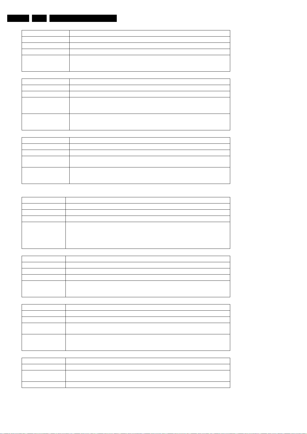
EN 64 DVDR70 & DVDR75/0x15.
Nucleus Name DS_SDRAM_WriteReadFast
Nucleus Number 401
Description Check all data lines and address lines of the SDRAM
User Input None
Example DS:> 401
040100:
Test OK @
Nucleus Name DS_SDRAM_Write
Nucleus Number 402
Description Write to a specific memory address
User Input 1. The location that must be modified
( SDRAM starts at address 0xA0000000 )
2. The value to put on the selected location
Example DS:> 402 0xa1000010 0xad112222
040200:
Test OK @
Nucleus Name DS_SDRAM_Read
Nucleus Number 403
Description Read from a specific memory address
User Input The location from which the data must be read
( SDRAM starts at address 0xA0000000 )
Example DS:> 403 0xa1000010
040300: Value read = 0xAD112222
Test OK @
Diagnostic Software
FLASH
Nucleus Name DS_FLASH_DevTypeGet
Nucleus Number 500
Description Get the device (revision) type information of the FLASH IC. (manufacturer and device ID)
User Input None
Example DS:> 500
050000: Found FLASH memory:
Manufacturer ID: 0x01
Device ID : 0x01
Test OK @
Nucleus Name DS_FLASH_WriteRead
Nucleus Number 501
Description Check whether the FLASH can be written to and read from
User Input None
Example DS:> 501
050100:
Test OK @
Nucleus Name DS_FLASH_Read
Nucleus Number 502
Description Read from a specific memory address in FLASH
User Input The location from which data must be read
( FLASH starts at address 0xB8000000 )
Example DS:> 502 0xb8000000
050200: Value read = 0x3C08A000
Test OK @
Nucleus Name DS_FLASH_ChecksumProgram
Nucleus Number 503
Description Check the checksum of the application partitions by recalculating and comparing partition
checksums
User Input None
Page 65
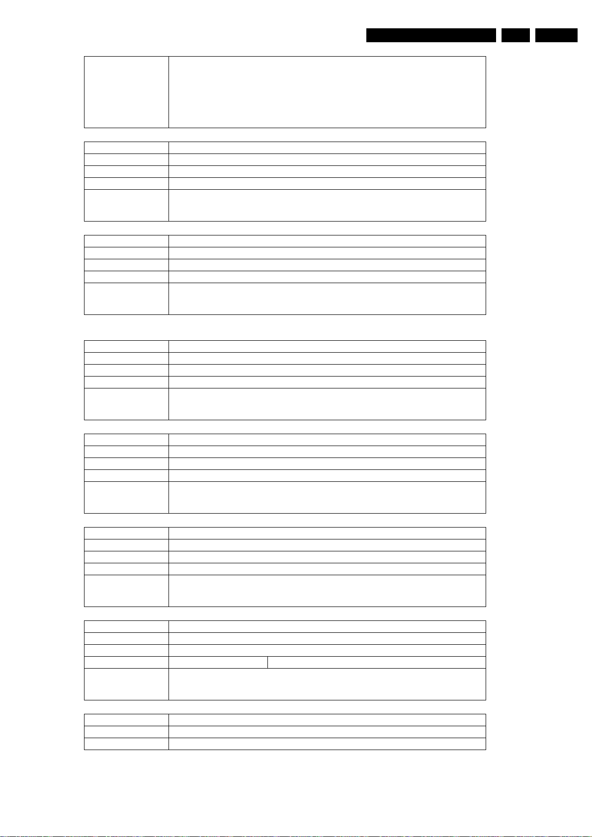
Diagnostic Software
EN 65DVDR70 & DVDR75/0x1 5.
Example DS:> 503
Nucleus Name DS_FLASH_CalculateChecksum
Nucleus Number 504
Description Calculate the checksum over all memory addresses. Used to check entire FLASH contents
User Input None
Example DS:> 504
Nucleus Name DS_FLASH_CalculateChecksumFast
Nucleus Number 505
Description Calculate a checksum over a selected number of address locations
User Input None
Example DS:> 505
050300:
BootCode checksum is: 0xBABE5B6F, which is correct
Diagnostics checksum is : 0xBABEBAFF, which is correct
Download checksum is: 0xBABEEDBF, which is correct
Application checksum is : 0xBABE8EEC, which is correct
Test OK @
050400: The Checksum = 0xBABE30A4
Test OK @
050500: The Checksum = 0xBABEB064
Test OK @
Video Input Processor (VIP)
Nucleus Name DS_VIP_DevTypeGet
Nucleus Number 600
Description Get the device (revision) type information of the VIP IC
User Input None
Example DS:> 600
060000: Found SAA7118
Test OK @
Nucleus Name DS_VIP_Communication
Nucleus Number 601
Description Check the communication between the IIC controller of the chrysalis and the VIP IC
User Input None
Example DS:> 601
060100:
Test OK @
Nucleus Name DS_VIP_ClockOutputOn
Nucleus Number 602
Description Switch the clock output on
User Input None
Example DS:> 602
060200:
Test OK @
Nucleus Name DS_VIP_ClockOutputOff
Nucleus Number 603
Description Switch the clock output off
User Input None
Example DS:> 603
Nucleus Name DS_VIP_SelectInput
Nucleus Number 604
Description Select an input video path to be switched to the analogue output pin (AOUT) of the VIP
060300:
Test OK @
Page 66
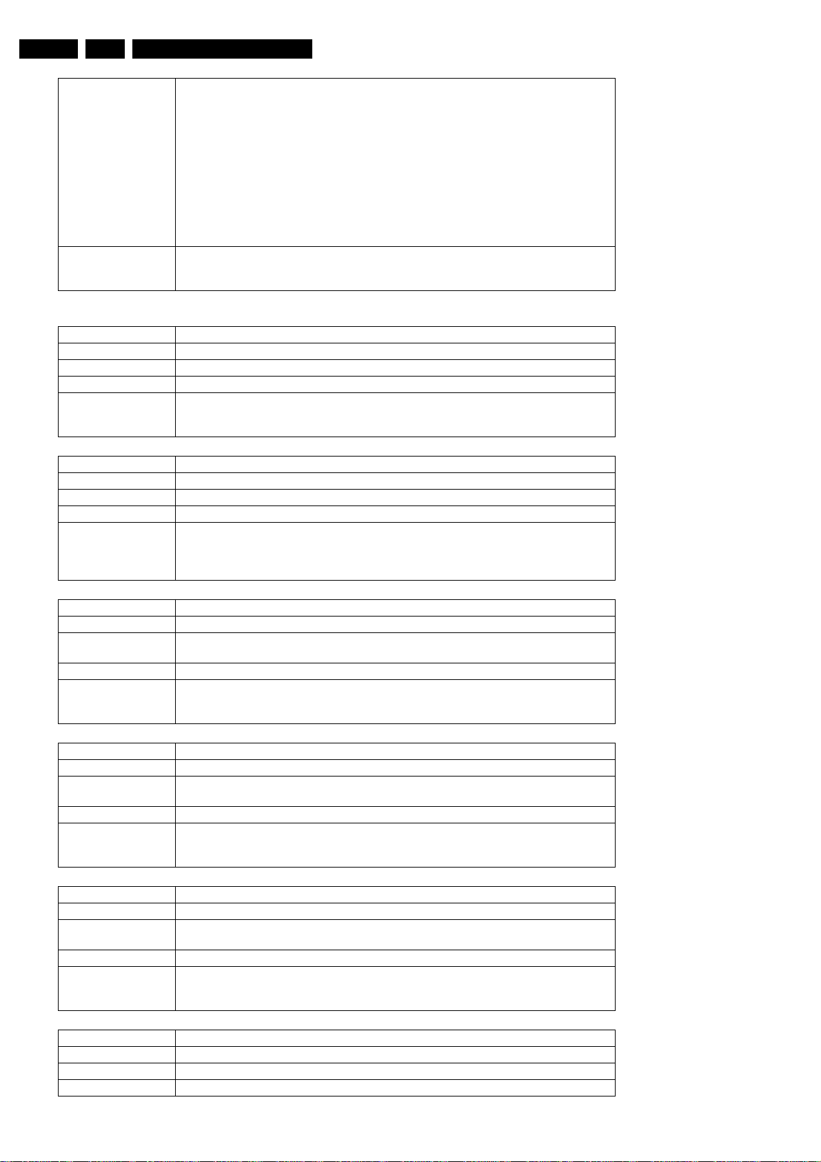
EN 66 DVDR70 & DVDR75/0x15.
Diagnostic Software
User Input The input to select, see table below.
Example DS:> 604 1
1 CVBS_Y_IN_A
2 CVBS_OUT_B
3 CVBS_Y_IN_B
4 CVBS_Y_IN_C
6 C_IN
8 G_IN
9 Y_IN
13 B_IN
14 U_IN
18 R_IN
19 V_IN
060400:
Test OK @
Digital Video Input Output (DVIO)
Nucleus Name DS_DVIO_LinkDevTypeGet
Nucleus Number 700
Description Get the device (revision) type information of the 1394 Link layer IC
User Input None
Example DS:> 700
Nucleus Name DS_DVIO_PhyDevTypeGet
Nucleus Number 701
Description Get the device (revision) type information of the 1394 Physical layer IC
User Input None
Example DS:> 701
070000: Device type of the link layer IC: ffc00301
Test OK @
070100:
Device type of the phy layer IC: 0
Test OK @
Nucleus Name DS_DVIO_LinkCommunication
Nucleus Number 702
Description Check the accessibility of the 1394 Link layer IC by writing to and reading from a specific
address
User Input None
Example DS:> 702
Nucleus Name DS_DVIO_PhyCommunication
Nucleus Number 703
Description Check the accessibility of the 1394 Physical layer IC by writing to and reading from a spe-
User Input None
Example DS:> 703
Nucleus Name DS_DVIO_Routing
Nucleus Number 704
Description Route a DV stream containing an audio and video signal through the physical and link layer
User Input None, test works for both NTSC and PAL
Example DS:> 704
070200:
Test OK @
cific address
070300:
Test OK @
ICs to the Chrysalis
070400:
Test OK @
Nucleus Name DS_DVIO_DetectNode
Nucleus Number 705
Description Check whether a DV node can be detected by the hardware
User Input None, test works for both NTSC and PAL
Page 67
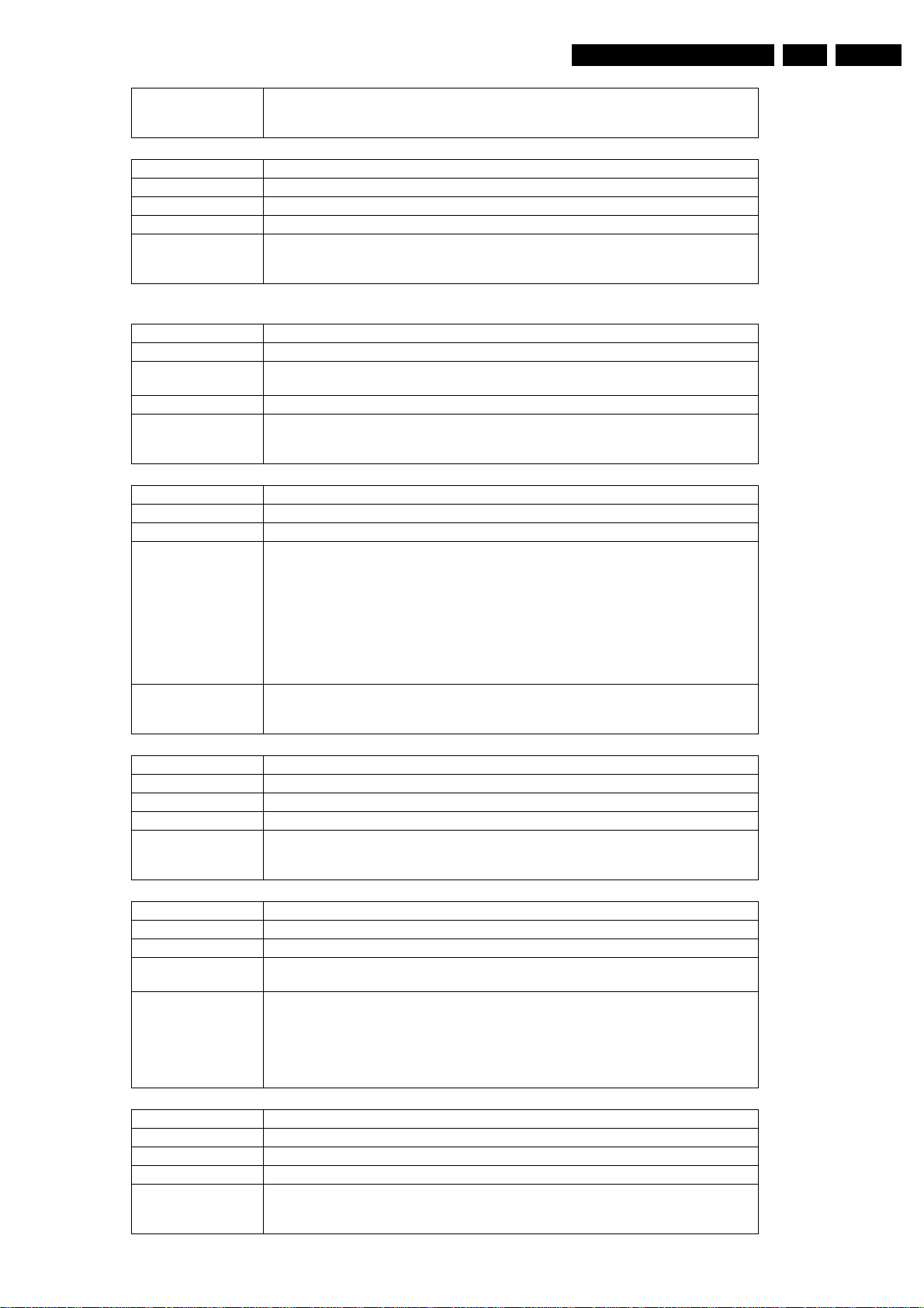
Diagnostic Software
EN 67DVDR70 & DVDR75/0x1 5.
Example DS:> 705
Nucleus Name DS_DVIO_DetectStream
Nucleus Number 706
Description Check whether a DV stream can be detected by the hardware
User Input None, test works for both NTSC and PAL
Example DS:> 706
070500:
Test OK @
070600:
Test OK @
Progressive Scan (PSCAN)
Nucleus Name DS_PSCAN_CommunicationDenc
Nucleus Number 801
Description Check the communication between the IIC controller of the chrysalis and the progressive
scan DENC-IC
User Input None
Example DS:> 801
Nucleus Name DS_PSCAN_TestImageOn
Nucleus Number 802
Description Generate the test images that are present on the progressive scan IC.
User Input In case of ADV7196:
Example DS:> 802 HATCH
080100:
Test OK @
When no input is given “HATCH” is the default
-“HATCH”
-“FRAME”
Remark:
“HATCH” is a crosshatch test pattern (horizontal and vertical white lines are displayed
against a black background)
“FRAME” is a uniform coloured frame/field test pattern (default white).
In case of FLI2300: Nothing.
080200:
Test OK @
Nucleus Name DS_PSCAN_TestImageOff
Nucleus Number 803
Description Switch off the generated test image
User Input None
Example DS:> 803
Nucleus Name DS_PSCAN_TestImageColourSettingsSet
Nucleus Number 804
Description Set the colour of the hatch- or the frame- field to a different value than the default white
User Input A colour string of one of the next non-case sensitive strings ( WHITE, BLACK, RED,
Example DS:> 804 yellow
Nucleus Name DS_PSCAN_TestImageColourSettingsGet
Nucleus Number 805
Description Get the colour settings of the hatch- or the frame- field.
User Input None
Example DS:> 805
080300:
Test OK @
GREEN, BLUE, YELLOW, CYAN, MAGENTA ) or Y Cr Cb (hexa-) decimal values.
080400:
Test OK @
DS:> 804 0x6a 0xde 0xca
080400:
Test OK @
080500: Colour Y Cr Cb values: 0xD2 0x92 0x10
Test OK @
Page 68
EN 68 DVDR70 & DVDR75/0x15.
Nucleus Name DS_PSCAN_Routing
Nucleus Number 806
Description Route a video signal from the host processor through the progressive scan ICs to the pro-
gressive scan output of the set.
Note: to route the progressive scan to the output of the set, first call nucleus 1112 with pa-
rameter 0 (video routing on analogue board).
User Input None
Example DS:> 806
080600:
Test OK @
Nucleus Name DS_PSCAN_DevTypeGetDeinterlacer
Nucleus Number 807
Description Get the device (revision) type information of the progressive scan deinterlacer.
User Input None
Example DS:> 807
080700:
Chip name : 2300
Chip version : 1
Test OK @
Nucleus Name DS_PSCAN_CommunicationDeinterlacer
Nucleus Number 808
Description Check the communication between the IIC controller of the chrysalis and the progressive
scan Deinterlacer-IC
User Input None
Example DS:> 808
080800:
Test OK @
Diagnostic Software
Basic Engine (BE)
Nucleus Name DS_BE_CommunicationEcho
Nucleus Number 900
Description Check the communication between the digital board and the basic engine by issuing an
echo command over the S2B interface
User Input None
Example DS:> 900
090000:
Test OK @
Nucleus Name DS_BE_Reset
Nucleus Number 901
Description Reset the basic engine
User Input None
Example DS:> 901
Nucleus Name DS_BE_VersionGet
Nucleus Number 903
Description Get the version of the basic engine and that of the optical unit
User Input None
Example DS:> 903
090100:
Test OK @
090300: BE version = 20.09.18 Optical unit version = 3C.00.09.41.08
Test OK @
Nucleus Name DS_BE_GetSelftestResult
Nucleus Number 902
Description Return the self-test results through the service port
User Input None
Example DS:> 902
090200:
Test OK @
Page 69
Diagnostic Software
Nucleus Name DS_BE_TrayOut
Nucleus Number 904
Description Open the tray of the basic engine
User Input None
Example DS:> 904
090400:
Test OK @
Nucleus Name DS_BE_TrayIn
Nucleus Number 905
Description Close the tray of the basic engine
User Input None
Example DS:> 905
090500:
Test OK @
Nucleus Name DS_BE_WriteReadDvdRw
Nucleus Number 906
Description Write data to and read data from a DVD+RW disc through the basic engine for verification
of the writing
User Input None
Example DS:> 906
090600: Testing on sector 0x5dbe0: OK
Test OK @
EN 69DVDR70 & DVDR75/0x1 5.
Nucleus Name DS_BE_WriteReadDvdR
Nucleus Number 907
Description Write data to and read data from a DVD+R disc through the basic engine for verification of
User Input None
Example DS:> 907
Nucleus Name DS_BE_StatisticalInformationGet
Nucleus Number 908
Description Retrieve the statistical information from the basic engine
User Input None
Example DS:> 908
Nucleus Name DS_BE_StatisticalInformationReSet
Nucleus Number 909
Description Reset the statistical information in the basic engine
User Input None
Example DS:> 909
the writing
090700: Testing on sector 0x36210: OK
Test OK @
Number of times Tray went Open/Closed : 4
Total minutes the CD laser was on : 0
Total minutes the DVD laser was on : 0
Total minutes the write laser was on : 0
090800:
Test OK @
090900:
Test OK @
Nucleus Name DS_BE_ErrorLogGet
Nucleus Number 910
Description Get the error log from the basic engine
User Input None
Example DS:> 910
Momentary errors (0-9): 0x21 0x00 0x00 0x20 0x00 0x00 0x00 0x00 0x00 0x00
Cumulative errors (1-9): 0x00 0x80 0x20 0x00 0x00 0x00 0x00 0x00 0x00
Software fatal assert : 256 cpowermanager.cpp
091000:
Test OK @
Page 70
EN 70 DVDR70 & DVDR75/0x15.
Nucleus Name DS_BE_ErrorLogReset
Nucleus Number 911
Description Reset the error log in the basic engine
User Input None
Example DS:> 911
091100:
Test OK @
Nucleus Name DS_BE_JitterOptimise
Nucleus Number 912
Description Perform jitter optimisation:
A formatted DVD must be loaded into the engine before executing this nucleus
User Input none
Example DS:> 912
Test OK @
Nucleus Name DS_BE_FocusOn
Nucleus Number 913
Description Put the laser of the BE into focus
User Input None
Example DS:> 913
091300:
Test OK @
Diagnostic Software
Nucleus Name DS_BE_FocusOff
Nucleus Number 914
Description Turn off putting the laser of the BE into focus
User Input None
Example DS:> 914
091400:
Test OK @
Nucleus Name DS_BE_MotorOn
Nucleus Number 915
Description Turn on the turntable motor
User Input None
Example DS:> 915
091500:
Test OK @
Nucleus Name DS_BE_MotorOff
Nucleus Number 916
Description Turn off the turntable motor
User Input None
Example DS:> 916
Nucleus Name DS_BE_RadialOn
Nucleus Number 917
Description Close the radial loop
User Input A formatted DVD must be loaded into the engine before executing this nucleus
Example DS:> 917
091600:
Test OK @
091700:
Test OK @
Nucleus Name DS_BE_RadialOff
Nucleus Number 918
Description Open the radial loop
User Input None
Example DS:> 918
091800:
Test OK @
Page 71
Diagnostic Software
Nucleus Name DS_BE_RadialCalibration
Nucleus Number 919
Description Calibrate the radial loop
User Input A formatted DVD must be loaded into the engine before executing this nucleus
Example DS:> 919
091900:
Test OK @
Nucleus Name DS_BE_Tilt
Nucleus Number 920
Description Test the tilt mechanism control loop, or allow its proper functioning to be measured.
Before executing this nucleus a disc must be loaded into the recorder
User Input None
Example DS:> 920
092000:
Tilt sensor bathtub: (71,-12,145)(68,-12,135)(62,-10,120)(56,-92,97)(50,-75,86)
(44,-59,80)(41,-52,80)(35,-37,86)(29,-22,86)
(23,-7,92)(17,8,111)(11,23,135)(8,31,138)(5,39,158)
Test OK @
Nucleus Name DS_BE_CheckDisc
Nucleus Number 921
Description Check whether there is a disc inside the BE
User Input None
Example DS:> 921
092100: A DVD+Rewritable is loaded (disc is empty or partially recorded)
Test OK @
DS:> 921
092100: No Disc is loaded
Test OK @
EN 71DVDR70 & DVDR75/0x1 5.
Nucleus Name DS_BE_SledgeMotor
Nucleus Number 922
Description Send the sledge to its home position, then to the middle of the disc, and then to the
end.
User Input None
Example DS:> 922
Nucleus Name DS_BE_ReadTocInfo
Nucleus Number 924
Description Read the TOC from the disc. This gives a good indication if the BE works properly..
User Input None
Example DS:> 924
092200:
Test OK @
092400:
TOC info [hex] = 91 3A 0C
Test OK@
DS:> 924
092403:
The BE returned: 0x10 #{no_disc_error} No disc is detected
Error@
DS:> 924
092403: The BE returned: 0x1e #{illegal_medium_error} Engine unable to handle
current disc. Probably illegal medium.
Error @
Nucleus Name DS_BE_DiscErase
Nucleus Number 925
Description Perform a DC-erase on a DVD+RW disc.
User Input None
Page 72
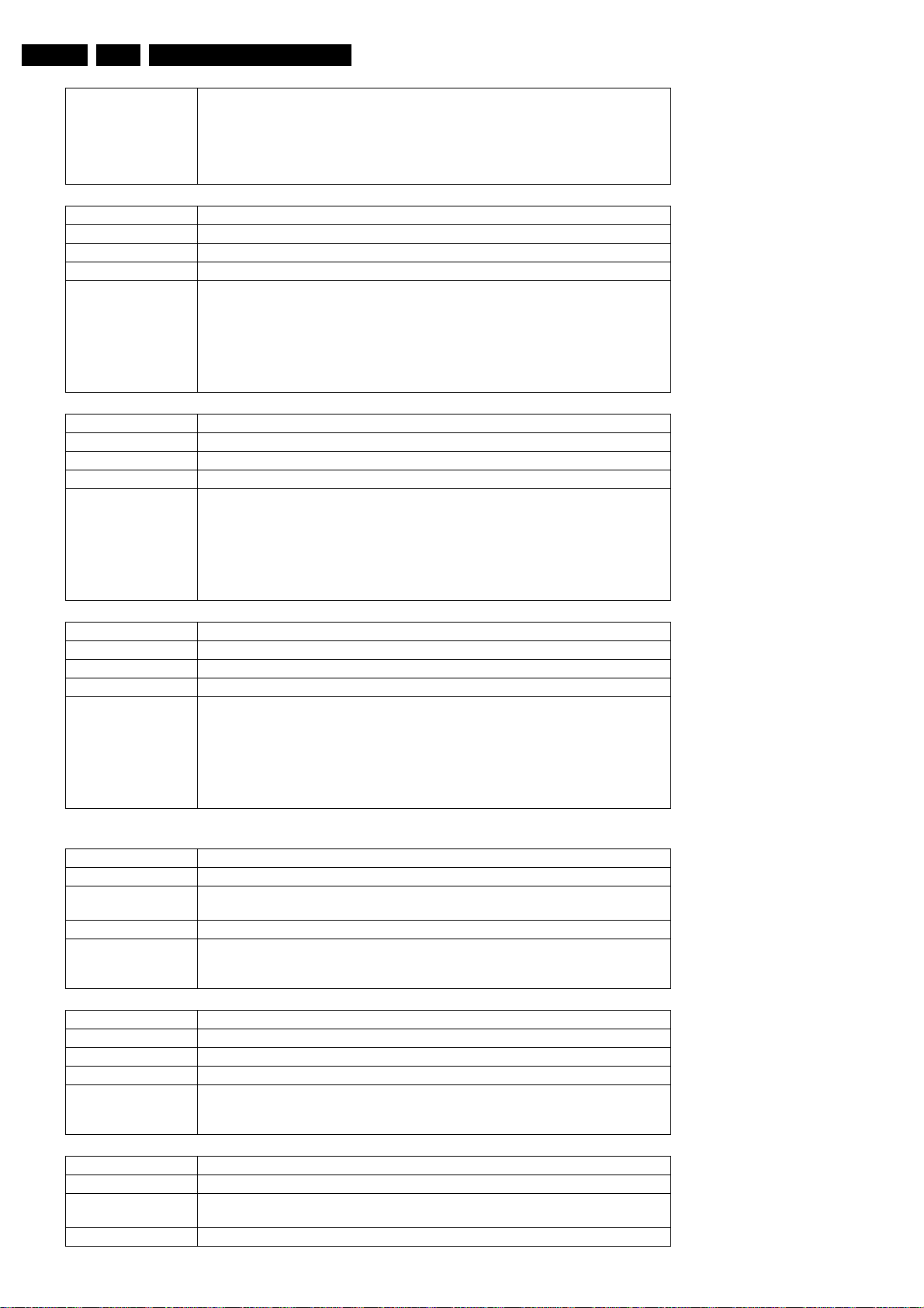
EN 72 DVDR70 & DVDR75/0x15.
Diagnostic Software
Example DS:> 925
Nucleus Name DS_BE_RegionCodeSet
Nucleus Number 928
Description Set the region code in the AV3.
User Input Region code
Example DS:> 928 1
Nucleus Name DS_BE_RegionCodeGet
Nucleus Number 929
Description Read the region code from the AV3.
User Input None
Example DS:> 929
The entirely disc will be erased.
Are you sure you want this?[y/n]
092500:
Test OK @
092800:
Test OK @
DS:> 928 This nucleus is not supported by the engine
092800:
Test OK @
092900: DVD region 1
Test OK @
DS:> 929This nucleus is not supported by the engine
092900:
Test OK @
Nucleus Name DS_BE_RegionCounterReset
Nucleus Number 930
Description Reset the region counter in the AV3.
User Input None
Example DS:> 930
093000:
Test OK @
DS:> 930 This nucleus is not supported by the engine
093000:
Test OK @
Display and Control Board (DCB)
Nucleus Name DS_DCB_CommunicationEcho
Nucleus Number 1000
Description Check the communication between the digital board and the DCB by issuing an echo
User Input None
Example DS:> 1000
command
100000:
Test OK @
Nucleus Name DS_DCB_VersionGet
Nucleus Number 1001
Description Get the version of the DCB
User Input None
Example DS:> 1001
100100: DCB version: 13
Test OK @
Nucleus Name DS_DCB_LightDisplay
Nucleus Number 1002
Description Light the entire display of the DCB, and clear the display after confirmation.
User Input None
User confirmation is necessary.
Page 73
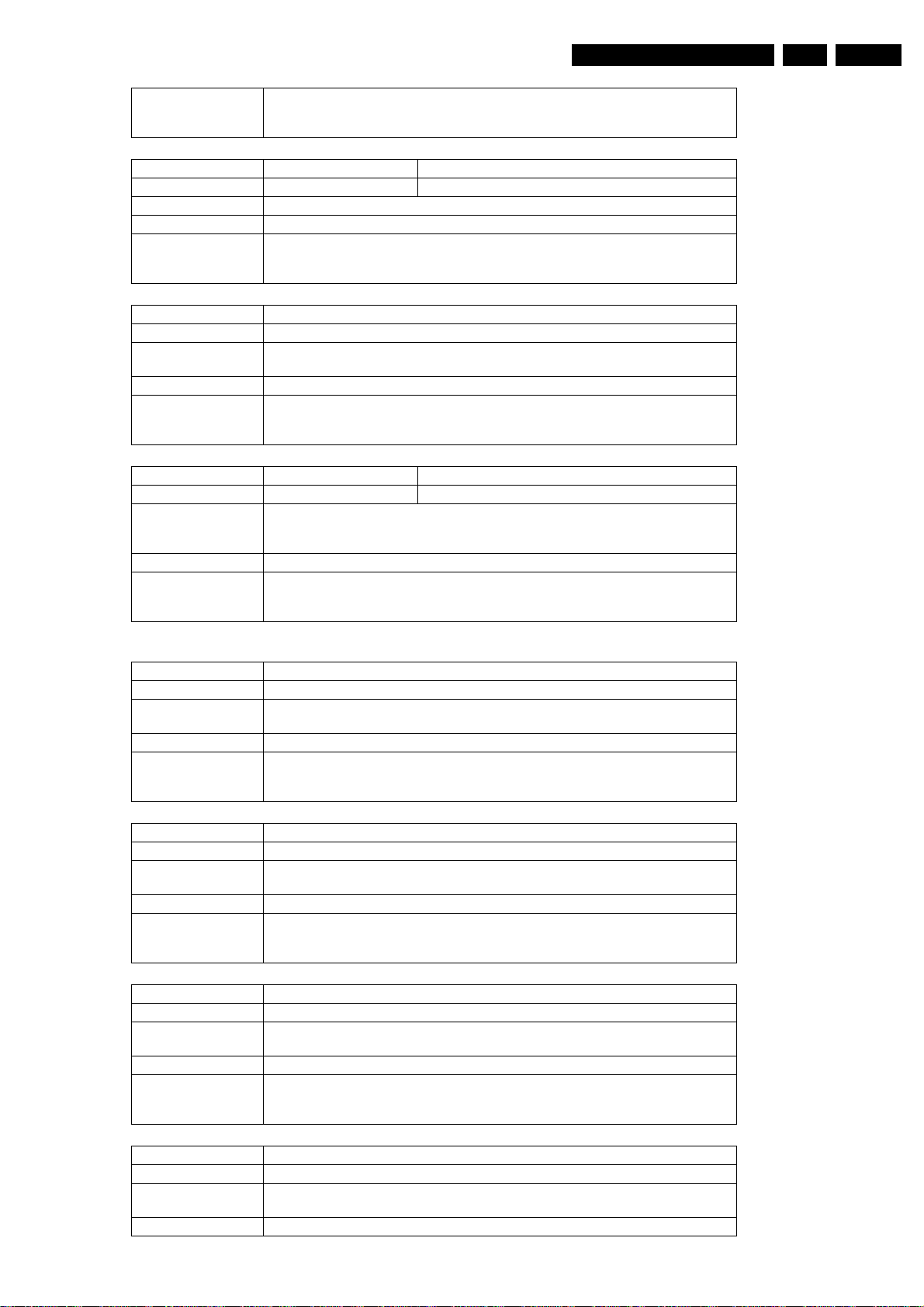
Diagnostic Software
EN 73DVDR70 & DVDR75/0x1 5.
Example DS:> 1002
Nucleus Name DS_DCB_Keyboard
Nucleus Number 1004
Description Check all keys of the keyboard by confirming the key-code displayed of each key.
User Input None
Example DS:> 1004
Nucleus Name DS_DCB_RemoteControl
Nucleus Number 1005
Description Check the interface between the remote control and the DCB by checking the key-
User Input None
Example DS:> 1005
Nucleus Name DS_DCB_Led
Nucleus Number 1006
Description Switch the record LED on, and after confirmation off.
User Input None
Example DS:> 1006
100200:
Test OK @
100400:
Test OK @
code displayed
100500:
Test OK @
The user confirms by pressing the REC key, STOP key, or the PLAY key on the local
keyboard. The PLAY key confirms that the LED is on and the REC key
100600:
Test OK @
Analogue Board (ANAB)
Nucleus Name DS_ANAB_CommunicationEcho
Nucleus Number 1100
Description Check the communication between the digital board and the analogue board by issu-
User Input None
Example DS:> 1100
Nucleus Name DS_ANAB_CommunicationIicNvram
Nucleus Number 1101
Description Check the communication between the digital board and the NVRAM on the analogue
User Input None
Example DS:> 1101
Nucleus Name DS_ANAB_CommunicationIicTuner
Nucleus Number 1102
Description Check the communication between the digital board and the tuner on the analogue
User Input None
Example DS:> 1102
ing some echo string.
110000: Hello Analogue Board
Test OK @
board.
110100:
Test OK @
board
110200:
Test OK @
Nucleus Name DS_ANAB_CommunicationIicDataSlicer
Nucleus Number 1103
Description Check the communication between the digital board and the data slicer on the ana-
User Input None
logue board
Page 74
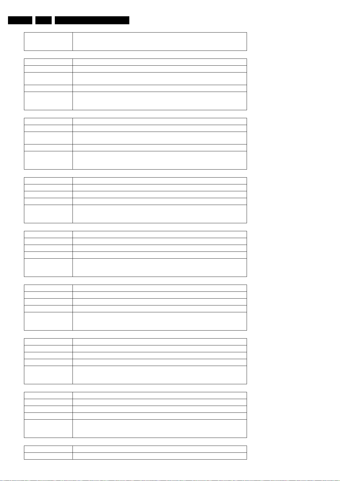
EN 74 DVDR70 & DVDR75/0x15.
Diagnostic Software
Example DS:> 1103
Nucleus Name DS_ANAB_CommunicationIicSoundProcessor
Nucleus Number 1104
Description Check the communication between the digital board and the sound processor on the
User Input None
Example DS:> 1104
Nucleus Name DS_ANAB_CommunicationIicAVSelector
Nucleus Number 1105
Description Check the communication between the digital board and the A/V-selector on the ana-
User Input None
Example DS:> 1105
Nucleus Name DS_ANAB_HardwareVersionGet
Nucleus Number 1106
Description Get the hardware version of the analogue board
User Input None
Example DS:> 1106
110300:
Test OK @
analogue board
110400:
Test OK @
logue board
110500:
Test OK @
110600: Analogue hardware version : 11
Test OK @
Nucleus Name DS_ANAB_SoftwareVersionBootGet
Nucleus Number 1107
Description Get the software version of the boot software of the analogue board
User Input None
Example DS:> 1107
110700: Bootcode application version : 11.00.11
Test OK @
Nucleus Name DS_ANAB_SoftwareVersionDownloadGet
Nucleus Number 1108
Description Get the software version of the download software of the analogue board
User Input None
Example DS:> 1108
Nucleus Name DS_ANAB_SoftwareVersionApplGet
Nucleus Number 1109
Description Get the software version of the application software of the analogue board
User Input None
Example DS:> 1109
Nucleus Name DS_ANAB_SoftwareVersionDiagnosticsGet
Nucleus Number 1110
Description Get the software version of the diagnostic software of the analogue board
User Input None
Example DS:> 1110
110800: Download application version : 11.00.06
Test OK @
110900: Recorder application version : 11.00.23
Test OK @
111000: Diagnostics application version : 11.00.13
Test OK @
Nucleus Name DS_ANAB_ChecksumProgram
Nucleus Number 1111
Page 75
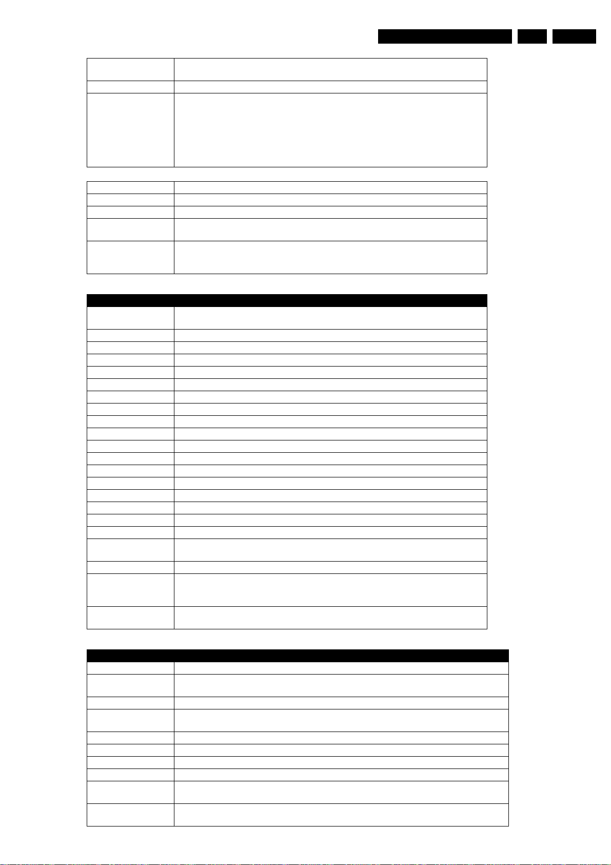
Diagnostic Software
EN 75DVDR70 & DVDR75/0x1 5.
Description Check the checksum of the several partitions by recalculating and comparing partition
User Input None
Example DS:> 1111
Nucleus Name DS_ANAB_VideoRouting
Nucleus Number 1112
Description Perform the routing of the video paths on the analogue board
User Input The user has to input the correct parameter for the routing (see table 'video routing'
Example DS:> 1112 00
checksums
BootCode checksum is: 0xBABE6240, which is correct
Diagnostics checksum is : 0xBABEBEAD, which is correct
Download checksum is: 0xBABEA6B7, which is correct
Application checksum is : 0xBABEB277, which is correct
111100:
Test OK @
below).
111200:
Test OK @
Video routing paths (Europe)
Path ID Description
0 Input signal is VIDEO(CVBS) from digital board and will be re-routed back to the digital
board.
1 Input signal is from FRONT VIDEO(CVBS) IN and will be routed to the digital board.
2 No Routing.
3 Input signal is from FRONT S-VIDEO(Y/C) and will be routed to the digital board.
4 No Routing.
5 Input signal is CVBS from SCART1 and will be routed to the digital board.
6 Input signal is CVBS from SCART2 and will be routed to the digital board.
7 Input Signal is CVBS from Digital Board and it will be routed to Scart1 and Scart2.
8 Input signal is VIDEO(CVBS) from ANTENNA IN and will be routed to SCART2.
9 Input signal is VIDEO(CVBS) from SCART1 and will be routed to SCART2.
10 Input signal is VIDEO(CVBS) from SCART2 and will be routed to SCART1.
11 Signal path is routed Fast Blank from Scart2 pin16 and will be routed SCART1 pin16
12 Input Signal is YC from Digital Board and it will be routed to SCART1.
13
14 No Routing.
15 Input Signal is CVBS from TUNER and it will be routed to Digital .
16 No Routing.
17 Input Signal is routed from digital board YC to REAR S-VIDEO(YC) OUT
18 Signal path is routed from digital board RGB to RGB SCART1 and from digital board
CVBS to digital board CVBS.
19 No Routing.
20 Input RGB Signal is routed from Digital Board to SCART1(RGB),Input CVBS Signal
21 Input Y/C Signal from Digital Board is routed to Rear Y/C Connector and Input Y/C Sig-
from Digital Board to Digital Board and Fast Blanking Signal from SCART2 to
SCART1.
nal from Front Y/C connector is routed to Digital Board.
Video routing paths (NAFTA)
Path ID Description
0 No Routing.
1 Input signal is from FRONT VIDEO(CVBS) IN and will be routed to the digital board.This rout-
ing is same as the above path id.
2 Input signal is from REAR VIDEO(CVBS) IN and will be routed to the digital board.
3 Input signal is from FRONT S-VIDEO(Y/C) IN and the signal received will be routed to the
4 Input signal is from REAR S-VIDEO(Y/C) IN and will be routed to the digital board.
5 No Routing.
6 No routing.
7 No routing.
8 Input signal is VIDEO(CVBS) from TUNER and will be routed to Y Pin of Rear Y/C Connec-
9 Input signal is from YUV IN and will be routed to YUV OUT.This is possible only if Digital
digital board.
tor.This will give only black/White Picture .
Board routes back YUV signal received back to the Analogue board(DENC)
Page 76
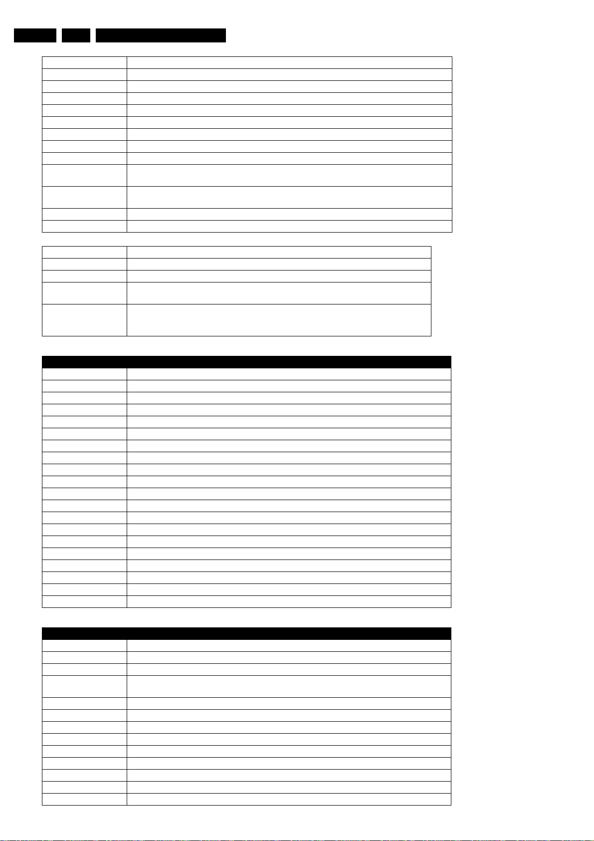
EN 76 DVDR70 & DVDR75/0x15.
10 No routing.
11 No routing.
12 No Routing.
13 No Routing.
14 No Routing.
15 Input CVBS Signal from Tuner is routed to Digital Board..
16 No Routing.
17 No Routing.
18 Input Signal from CVBS Rear In is routed to Digital Board. This is the same as path ID 02.
19 Input Y/C signal from Digital Board is routed to Y/C Rear Out Connector and Input signal from
Y/C Front In Connector is routed to Y/C Digital Board.
20 Y/C signal from Digital Board is routed to Y/C Rear Out Connector and Input signal from Y/
C Rear In Connector is routed to Y/C Digital Board.
23 The Video signal received from the Digital board will be output on Modulator channel 3.
24 The Video signal received from the Digital board will be output on Modulator channel 4.
Nucleus Name DS_ANAB_AudioRouting
Nucleus Number 1113
Description Perform the routing of the audio paths on the analogue board
User Input The user has to input the correct parameter for the routing (see table 'audio routing'
below)
Example DS:> 1113 00
111300:
Test OK @
Diagnostic Software
Audio routing paths (Europe)
Path ID Description
0 Input signal is from FRONT AUDIO IN and will be routed to the digital board.
1 Input signal is from FRONT AUDIO IN and will be routed to the digital board.
2 No Routing.
3 Input signal is AUDIO from SCART1 and will be routed to the digital board.
4 Input signal is AUDIO from SCART2 and will be routed to the digital board.
5 No routing.
6 No routing.
7 Input Audio signal is from the digital Board and it will be routed to the SCART1 and SCART2
8 Input AUDIO signal from TUNER and will be routed to SCART2.
9 Input signal is AUDIO from SCART1 and will be routed to SCART2.
10 Input audio signal from SCART2 is routed to SCART1.
11 Input Audio signal is routed from DVIO to SCART2.
12
13 No Routing.
14 Input is Audio Signal from DVIO and it will be routed to Digital Board.
15 Input is Audio Signal from TUNER and it will be routed to Digital Board..
16 No routing.
17 No Routing.
18 Input signal is from FRONT AUDIO IN and will be routed to SCART2.
21 Input signal is from FRONT AUDIO IN and will be routed to the digital board.
Audio routing paths (NAFTA)
Path ID Description
0 No Routing.
1 Input signal is from FRONT AUDIO IN and will be routed to the digital board.
2 Input signal is from REAR AUDIO IN 2 and will be routed to the digital board.
3 Input Audio Signal is routed from FRONT Cinch In to Digital Board.(This is same as path ID
01)
4 Input Signal is from Rear Cinch In1 and it will be routed to Digital Board..
5 No routing.
6 No routing.
7 No routing.
8 No Routing.
9 No routing.
10 No Routing.
11 No Routing.
12 No Routing.
Page 77
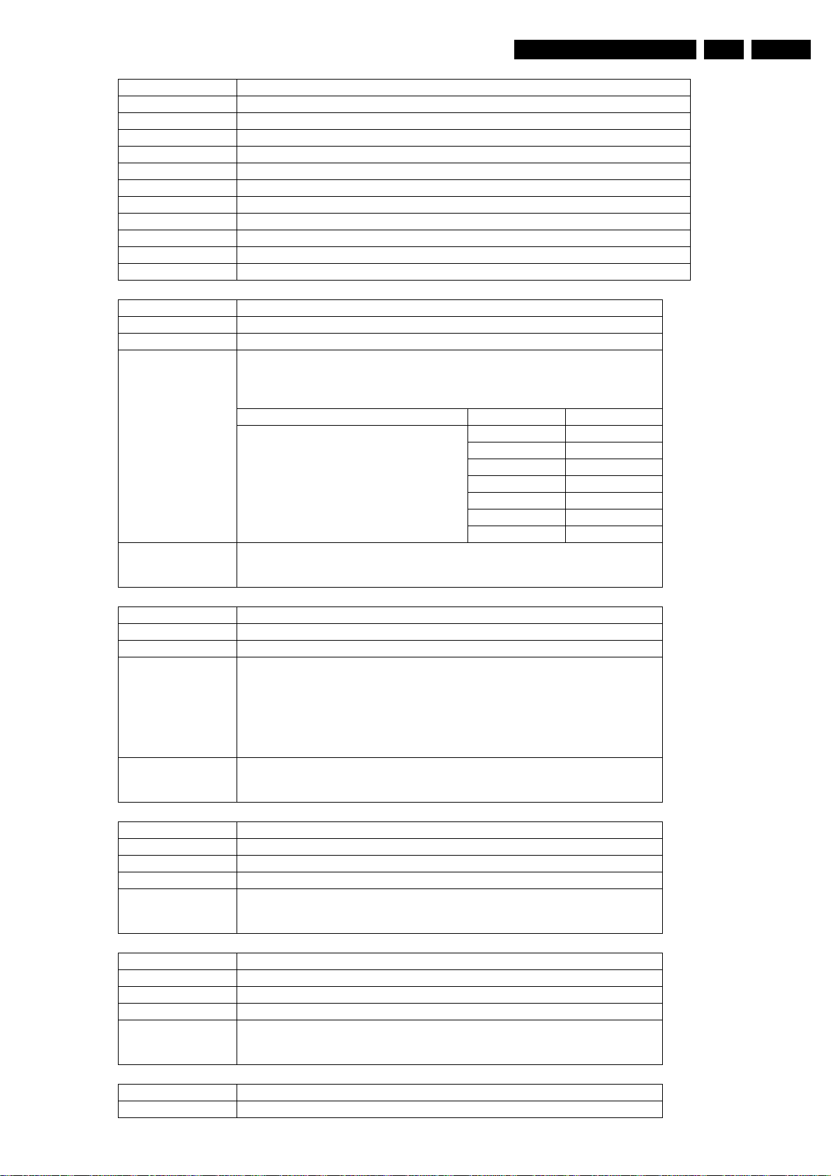
Diagnostic Software
13 Input Signal is from Digital Board and it will be routed to the digital board.
14 No routing.
15 Input is Audio Signal from TUNER and it will be routed to Digital Board.
16 Input signal is AUDIO from dvio board and will be routed to Digital Board.
17 No routing.
18 No routing.
19 No routing.
20 Input signal is from REAR AUDIO IN 2 and will be routed to the digital board.
21 Input signal is from REAR AUDIO IN 1 and will be routed to the digital board.
22 Input signal is from REAR AUDIO IN 1 and will be routed to the digital board.
23 The Audio signal received from the Digital board will be outputted on Modulator channel 3.
24 The Audio signal received from the Digital board will be outputted on Modulator channel 4.
Nucleus Name DS_ANAB_SelectTunerChannel
Nucleus Number 1114
Description Set the tuner to receive a valid audio and video signal
User Input <Fre quency*16> <video standard id>
Tuner frequency: to tune the tuner to e.g. 216 MHz, this parameter must be 3456.
(Since 216*16 = 3456. This is to avoid the decimal points to the parameter list.)
Video standard id: The table below shows which video standards are possible
Video standard id Europe NAFTA
16
32
48
64
80
96
112
Example DS:> 1114 3456 16
111400:
Test OK @
PAL_BG NTSC
PAL_I Invalid
PAL_DK Invalid
SEC_L Invalid
SEC_LS Invalid
SEC_BG Invalid
SEC_DK Invalid
EN 77DVDR70 & DVDR75/0x1 5.
Nucleus Name DS_ANAB_IICWriteRead
Nucleus Number 1115
Description Perform an IIC write and read action on the analogue board
User Input Writing:
[<W>|<w>] [I2C address] [number of data bytes to write]
with
<data[0]...data[n]> Max 16 data bytes (n < 16).
Reading:
[<R>|<r>] [I2C address] [number of data bytes to read]
Max 16 data bytes (n < 16).
Example DS:> 1115 w 0x94 2 0x06 0x02
111500:
Test OK @
Nucleus Name DS_ANAB_ClockAdjust
Nucleus Number 1116
Description Set the clock to the value passed through in the YYYY MM DD HH MM SS format
User Input <YYYY> <MM> <DD> <HH> <MM> <SS>
Example DS:> 1116 2002 11 11 11 11 11
Nucleus Name DS_ANAB_ClockReference
Nucleus Number 1117
Description Generate a 1 kHz signal on pin 7 (INT) of the clock IC
User Input None
Example DS:> 1117
111600:
Test OK @
111700:
Test OK @
Nucleus Name DS_ANAB_ClockCorrection
Nucleus Number 1118
Page 78
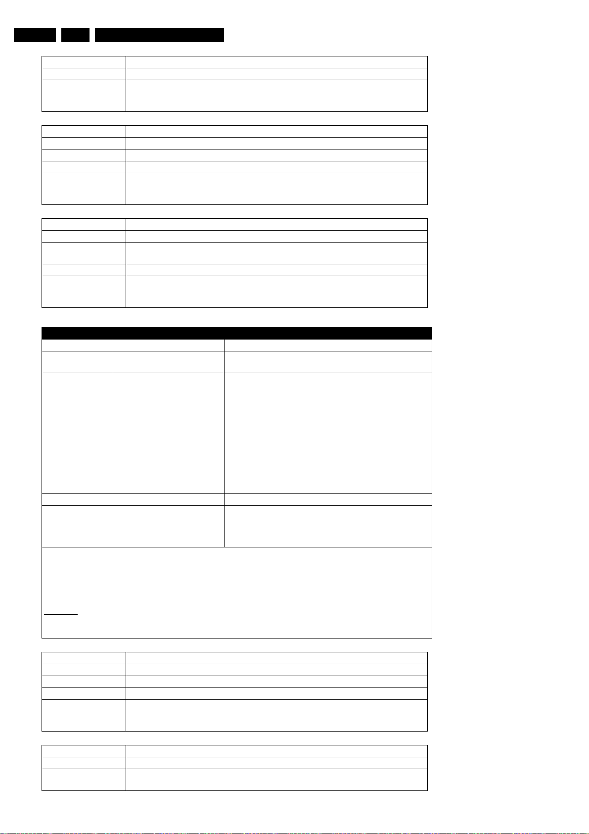
EN 78 DVDR70 & DVDR75/0x15.
Description Store the clock IC correction value in NVRAM
User Input The correction value for the clock
Example DS:> 1118 1000023
111800:
Test OK @
Nucleus Name DS_ANAB_TunerAFCReferenceVoltage
Nucleus Number 1119
Description Store the reference voltage for the tuner in NVRAM
User Input The reference voltage, between 0 and 255
Example DS:> 1119 5
111900:
Test OK @
Nucleus Name DS_ANAB_TunerFrequencyDownload
Nucleus Number 1120
Description Store the frequency table in NVRAM. The frequency table is passed through the error-
string provided to the nucleus.
User Input See frequency table
Example DS:> 1120 2233 00 02 4E45442031
112000:
Test OK @
Diagnostic Software
Frequency download string format
Format description remarks
X(XXX) Preset number
VVWW VV: Channel number
WW : Channel offset
ZZ Byte containing 8 bit fields for
TRUE/FALSE :
BIT 0: Decoder
BIT 1: Modulation
BIT 2: NICAM
SAP
BIT 3: Satpreset
BIT 4: Presetdefined
Channelpreferred
BIT 5: ExtPreset
BIT 6: NameManuallyChanged
BIT 7: ChannelPreset
HH HfSystemFineTuning HfS: 4 bit, FT: -4,...,4
IIJJKKLLMM Netname Range: A,..,Z,0,..,9,_,.. Netname length exists for Europe
The message string of (DS_MessageDef *msgString) should be in the format:
“X(XXX)_VVWW_ZZ_HH_IIJJKKLLMM”.
Here will be ‘X(XXX)’ a decimal value in the range of 0 to 255.
V, W, Z, H, I, J, K, L, M are hex values with out the prefix ‘0x’ (in the range 0... 9,A ... F)
“ _” Denotes a space character.
NICAM/stereo bit for Europe
SAP/stereo bit for NAFTA
Preset defined bit is only used for Europe. For NAFTA, it is
renamed as channelpreferred to indicate if a channel is preferred or not.
TRUE if preset is defined from P50 as extern [TGA]
only.
‘II’ is the HEX-value for the first character, ‘JJ’ for the second, Ö
Remarks:
CHANNEL_SYSTEM is for NAFTA.
PRESET_SYSTEM is for Europe.
Nucleus Name DS_ANAB_StoreExternalPresets
Nucleus Number 1121
Description Store the external presets in NVRAM
User Input None
Example DS:> 1121
112100:
Test OK @
Nucleus Name DS_ANAB_BargraphLevelAdjust
Nucleus Number 1122
Description Measure the audio signal corresponding to 0dB per channel and store it as correction
value in NVRAM
Page 79
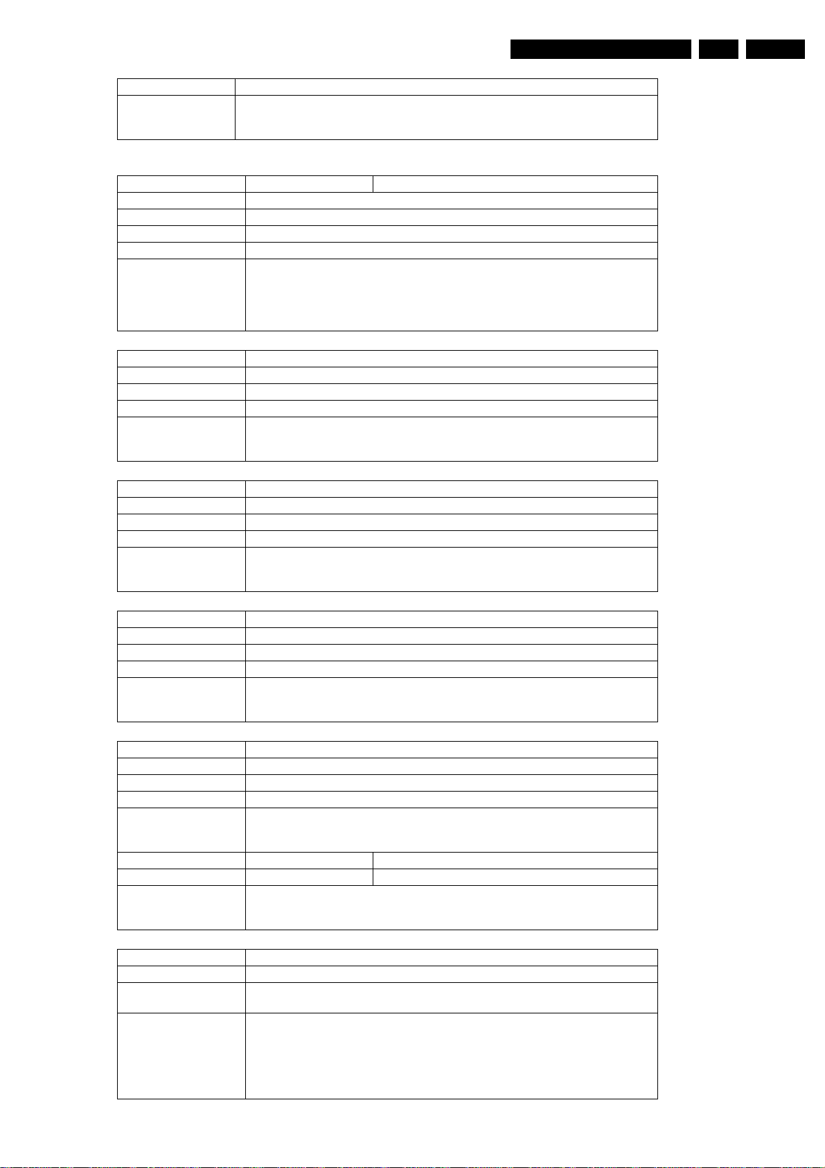
Diagnostic Software
User Input none
Example DS:> 1122
112200:
Test OK @
System (SYS)
Nucleus Name DS_SYS_HardwareVersionGet
Nucleus Number 1200
Description Get the hardware version and type of the digital board
User Input None
Example DS:> 1200
120000: Hardware ID = 00
The (PIO-pins) Digital Board ID = 2
Test OK @
DS:>
Nucleus Name DS_SYS_SoftwareVersionBootGet
Nucleus Number 1201
Description Get the version of the boot software on the digital board
User Input None
Example DS:> 1201
120100: Software Boot Version = 0001
Test OK @
EN 79DVDR70 & DVDR75/0x1 5.
Nucleus Name DS_SYS_SoftwareVersionDownloadGet
Nucleus Number 1202
Description Get the version of the download software on the digital board
User Input None
Example DS:> 1202
120200: Software Download Version = 0001
Test OK @
Nucleus Name DS_SYS_SoftwareVersionApplGet
Nucleus Number 1203
Description Get the version of the application software on the digital board
User Input None
Example DS:> 1203
120300: Software Application Version = 0001
Test OK @
Nucleus Name DS_SYS_SoftwareVersionDiagnosticsGet
Nucleus Number 1204
Description Get the version of the diagnostics software on the digital board
User Input None
Example DS:> 1204
Example DS:> 1205 1
120400: Software Diagnostics Version = 0001
Test OK @
120503 Something went wrong while transferring the data.
120504 User cancelled the upload.
120500:
Test OK @
Nucleus Name DS_SYS_EepromUpload
Nucleus Number 1205
Description Upload the contents of the NVRAM on the analogue board or the digital board to the
User Input Choose one of the following parameters for the nucleus:
service PC, by using the X-modem protocol
1. Upload the contents of the NVRAM of the digital board
2. Upload the contents of the NVRAM of the analogue board
Choose in the terminal on the control PC -> transfer -> receive file.
Select X-modem protocol. Then click receive in the dialogue and fill in the file name
in which you want to store the data.
Page 80
EN 80 DVDR70 & DVDR75/0x15.
Nucleus Name DS_SYS_EepromDownload
Nucleus Number 1206
Description Download a file with the contents of the NVRAM for the analogue board or the digital
board from the service PC to the recorder, by using the X-modem protocol
User Input Choose one of the following parameters for the nucleus:
1. Download the contents of the NVRAM of the digital board
2. Download the contents of the NVRAM of the analogue board
Choose in the terminal of the control PC -> transfer -> send file.
Select X-modem protocol. Then choose a file with the Browse button in the dialogue
and click on send.
Example DS:> 1206 1
120600:
Test OK @
Nucleus Name DS_SYS_DvIdNumberGet
Nucleus Number 1208
Description Get the IEEE1394 ID
User Input None
Example DS:> 1208
120800: The DvIdNumber is: 0x0C22384E5A
Test OK @
Nucleus Name DS_SYS_IicWrite
Nucleus Number 1209
Description Perform an IIC write action on the digital board
User Input The user input the number of bytes to write followed by these bytes:
<BusID><Slave address to write to><number of bytes to write><d1><d2><..><dx>
Where the bus ID is either 0 (normally used) or 1
Example DS:> 1209 0 0xa0 1 0x6
120900: 1 Bytes written
Test OK @
Diagnostic Software
Nucleus Name DS_SYS_IicRead
Nucleus Number 1210
Description Perform an IIC read action on the digital board
User Input The user inputs the number of bytes to read and the address to read them from:
Example DS:> 1210 0 0xa0 1
Nucleus Name DS_SYS_UartWrite
Nucleus Number 1211
Description Perform an UART write action on the digital board on a specified UART
User Input The user inputs the UART to write to, the number of bytes and the bytes to be written
Example DS:> 1211 2 2 0xd1 0x01
Nucleus Name DS_SYS_UartRead
Nucleus Number 1212
Description Perform an UART read action on the digital board on a specified UART
User Input The user inputs the UART to read from.
Example DS:> 1212 2
<BusID><Slave address to read from><Number of bytes to read>
Where the bus ID is either 0 (normally used) or 1
121000: Value read =0x06
Test OK @
to the UART.
1=UART port 1 : not used
2=UART port 2 : Bit Engine
3=UART port 3 : Analogue board
<UartNr><Number of bytes to write><d1><d2><..><dx>
121100:
Test OK @
1=UART port 1 : not used
2=UART port 2 : Bit Engine
3=UART port 3 : Analogue board
<UartNr >
121200: The value that was read is: 0x50 0xD1 0x00
Test OK @
Page 81
Diagnostic Software
Nucleus Name DS_SYS_VideoLoopThroughStart
Nucleus Number 1213
Description The video signal, which is confirm the user input, is routed from the input to the out-
put. Input is set with the routing nucleus 1112. All outputs are enabled.
User Input <vipInput> <VideoOutput> <VideoStandard>
1. vipInput (CVBS, YC, YUV, RGB).
2. VideoOutput (YUV, RGB).
3. VideoStandard (PAL, NTSC).
Example DS:> 1213 CVBS RGB PAL
121300:
Test OK @
Nucleus Name DS_SYS_VideoLoopThroughStop
Nucleus Number 1214
Description Stop routing the video input to all the outputs.
User Input Example DS:> 1214
121400:
Test OK @
Nucleus Name DS_SYS_VideoLoop
Nucleus Number 1215
Description Note: Before executing this nucleus the user must route the video signal on the an-
alog board with nucleus DS_ANAB_VideoRouting(1112 ).
User Input Video input of the digital board:
- CVBS
- YC
- YUV
- RGB
- TEST (The video output will be routed to the video input on the digital board.)
Video standard:
- PAL
- NTSC
When no input is given, the nucleus will take TEST for video input and PAL for video
standard.
Example DS:> 1215 cvbs ntsc
121500:
Test OK @
DS:> 1215 cvbs pal
121508: The VideoInputProcessor cannot detect a sync-signal.
Error @
DS:> 1215 yuv ntsc
121511:
Error in luminance signal(Y)
Error in chrominance signal(U)
Error in chrominance signal(V)
Error @
EN 81DVDR70 & DVDR75/0x1 5.
Nucleus Name DS_SYS_SlashVersionSet
Nucleus Number 1217
Description Set the slash version of the system
User Input The slash version
Example DS:> 1217 82
121700:
Test OK @
Nucleus Name DS_SYS_SlashVersionGet
Nucleus Number 1218
Description Get the slash version of the system
User Input None
Example DS:> 1218
121800: The slash version is: 82
Test OK @
Nucleus Name DS_SYS_Virginize
Nucleus Number 1219
Page 82
EN 82 DVDR70 & DVDR75/0x15.
Diagnostic Software
Description (Re-) Virginize the recorder. User data in the NVRAM of the analogue board is
Example DS:> 1219
Nucleus Name DS_SYS_VirginModeOn
Nucleus Number 1220
Description Turn on the virgin mode functionality (e.g. the auto channel search upon start-up)
User Input None
Example DS:> 1220
Nucleus Name DS_SYS_VirginModeOff
Nucleus Number 1221
Description Turn off the virgin mode functionality (e.g. the auto channel search upon start-up)
User Input None
Example DS:> 1221
Nucleus Name DS_SYS_DisplayFatalOn
Nucleus Number 1223
Description Turn on the display-fatal functionality which displays debug-information on the dis-
User Input None
Example DS:> 1223
cleared
121900:
Test OK @
122000:
Test OK @
122100:
Test OK @
play when encountering a fatal error condition from which could not be recovered automatically
122300:
Test OK @
Nucleus Name DS_SYS_DisplayFatalOff
Nucleus Number 1224
Description Turn off the display-fatal functionality which displays debug-information on the dis-
User Input None
Example DS:> 1224
Nucleus Name DS_SYS_DisplayFatalGet
Nucleus Number 1225
Description Get the display-fatal flag of the recorder
User Input None
Example DS:> 1225
Nucleus Name DS_SYS_SettingsSet
Nucleus Number 1226
Description Programs the digital board settings into the boot EEPROM on the digital board.
User Input A large hexadecimal value that represents the digital board settings obtained from
Example DS:> 1226 646961677473746201010200010101010101000020080000
play when encountering a fatal error condition from which could not be recovered automatically
122400:
Test OK @
122500:
Test OK @
the DbString.exe program or from a reference set.
122600:
Test OK @
Nucleus Name DS_SYS_SettingsDisplay
Nucleus Number 1228
Description Show the settings that are programmed in the BROM on the digital board.
User Input None.
Page 83
Diagnostic Software
EN 83DVDR70 & DVDR75/0x1 5.
Example DS:> 1228
Nucleus Name DS_SYS_SettingsGet
Nucleus Number 1229
Description Get the digital board diversity settings string that is programmed in the BROM on the
User Input None.
Example DS:> 1229
Settings ID: 6D7920626F61726400020300010101020101000020080000
Board name: my board
Hardware ID: 0
Codec IC: PNX7100_MF2
Video Input Processor IC: SAA7118
Progressive Scan Deinterlacer IC: None
Progressive Scan Denc IC: ADV7196
I-Link physical layer circuit IC: PDI1394P25
I-Link link layer circuit IC: PDI1394P40
Audio clock: Clock scheme 1
Bit engine connector: available
IDE connector 1: available
IDE connector 2: not available
PCI connector: not available
RAM size 32MByte
ROM size (NOR FLASH bank 1) 8MByte
ROM size (NOR FLASH bank 2) Not available
ROM size (NAND FLASH) Not available
Bit Engine: AV 2.0
122800:
Test OK @
digital board.
122900: 6D7920626F61726400020300010101020101000020080000
Test OK @
Nucleus Name DS_SYS_AudioLoopThroughStart
Nucleus Number 1230
Description Description: The audio input is routed from the an input to all outputs. Input is set with
User Input None.
Example DS:> 1230
Nucleus Name DS_SYS_AudioLoopThroughStop
Nucleus Number 1231
Description Stop routing the audio input to all the outputs
User Input Example DS:> 1231
Electronic Program Guide Board (EPGB)
Nucleus Name DS_EPGB_VersionGet
Nucleus Number 1300
Description Returns the version of the EPG board.
User Input None
Example DS:> 1300
the routing nucleus 1113. All outputs are enabled.
123000:
Test OK @
123100:
Test OK @
130000:
Version : 6.1.9
Test OK @
PCMCIA INTERFACE (PCMCIA)
Nucleus Name DS_PCMCIA_Reset
Nucleus Number 1400
Description Reset the PCMCIA device by sending a reset command through IDE
Example DS:> 1400
140000:
Test OK @
Page 84
EN 84 DVDR70 & DVDR75/0x15.
Nucleus Name DS_PCMCIA_Inquiry
Nucleus Number 1401
Description Get the vendor- and product identification and the product revision level of the media
in the slot.
Example DS:> 1401
140100:
Test OK @
Nucleus Name DS_PCMCIA_WriteRead
Nucleus Number 1402
Description Perform a Write Read test to a random sector on the inserted medium in the PCM-
CIA device and check if the data read is equal to the data written.
Example DS:> 1402
140200:
Test OK @
Nucleus Name DS_PCMCIA_Diagnostics
Nucleus Number 1403
Description Shall perform the internal diagnostic tests implemented by the media in the slot.
Example DS:> 1403
140300:
Test OK @
Diagnostic Software
Script
Nucleus Name DS_IH_ScriptHandler
Nucleus Number Script
Description
Included tests: 1. DS_ANAB_COMMUNICATIONECHO_NUC
2. DS_DCB_COMMUNICATIONECHO_NUC
3. DS_BROM_COMMUNICATION_NUC
4. DS_SYS_SETTINGSDISPLAY_NUC
5. DS_CHR_DEVTYPEGET_NUC
6. DS_CHR_INT_PIC_NUC
7. DS_CHR_DMA_NUC
8. DS_BROM_WRITEREAD_NUC
9. DS_NVRAM_COMMUNICATION_NUC
10. DS_NVRAM_WRITEREAD_NUC
11. DS_SDRAM_WRITEREADFAST_NUC
12. DS_FLASH_WRITEREAD_NUC
13. DS_FLASH_CHECKSUMPROGRAM_NUC
14. DS_SYS_HARDWAREVERSIONGET_NUC
15. DS_VIP_DEVTYPEGET_NUC
16. DS_VIP_COMMUNICATION_NUC
17. DS_DVIO_LINKDEVTYPEGET_NUC
18. DS_DVIO_PHYDEVTYPEGET_NUC
19. DS_DVIO_LINKCOMMUNICATION_NUC
20. DS_DVIO_PHYCOMMUNICATION_NUC
21. DS_PSCAN_COMMUNICATIONDENC_NUC
22. DS_PSCAN_COMMUNICATIONDEINTERLACER_NUC
23. DS_BE_COMMUNICATIONECHO_NUC
24. DS_ANAB_COMMUNICATIONIICNVRAM_NUC
25. DS_ANAB_COMMUNICATIONIICTUNER_NUC
26. DS_ANAB_COMMUNICATIONIICSOUNDPROCESSOR_NUC
27. DS_ANAB_COMMUNICATIONIICAVSELECTOR_NUC
28. DS_ANAB_CHECKSUMPROGRAM_NUC
User Input None
Page 85

Diagnostic Software
EN 85DVDR70 & DVDR75/0x1 5.
Example DS:> script
Executing User/Dealer script.
Busy executing NUC1100 1-28
Hello Analogue Board
Busy executing NUC1000 2-28
Busy executing NUC200 3-28
Busy executing NUC1228 4-28
Settings ID: 4C4541440D00000000030300010101020101000020080000
Board name: LEAD
Hardware ID: 0
Codec IC: PNX7100_MF3
Video Input Processor IC: SAA7118
Progressive Scan Deinterlacer IC: None
Progressive Scan Denc IC: ADV7196
I-Link physical layer circuit IC: PDI1394P25
I-Link link layer circuit IC: PDI1394P40
Audio clock: Clock scheme 1
Bit engine connector: available
IDE connector 1: available
IDE connector 2: not available
PCI connector: not available
RAM size 32MByte
ROM size (NOR FLASH bank 1) 8MByte
ROM size (NOR FLASH bank 2) Not available
ROM size (NAND FLASH) Not available
Bit Engine: AV 2.0
Busy executing NUC100 5-28
Device ID 7100
Codec ID PNX7100_MF3
F-BCU (0x0102) 1.0 INTC (0x011d) 1.0 PCI-XIO(0x0113) 1.0
SIF (0x013b) 1.0 EJTAG (0x0104) 0.0 S-BCU (0x0102) 1.0
BOOT (0x010a) 1.0 CONFIG (0x013f) 1.0 RESET (0x0123) 1.0
DEBUG (0x0116) 0.0 UART0 (0x0107) 0.1 UART1 (0x0107) 0.1
UART2 (0x0107) 0.1 UART3 (0x0107) 0.1 I2C0 (0x0105) 0.1
I2C1 (0x0105) 0.1 GPIO (0x013c) 1.0 SYNC (0x013a) 1.0
DISP0 (0xa015) 0.2 DISP1 (0xa00f) 0.0 OSD (0x0136) 0.1
SPU (0xa00e) 0.0 MIXER (0x0137) 1.0 DENC (0x0138) 0.1
CCIR (0x0139) 1.0 VDEC (0x0133) 0.1 PARSER (0xa00d) 0.0
DV (0xa00c) 0.0 BEI (0xa00a) 0.0 IDE (0xa009) 0.0
SGDX (0xa008) 0.0 BYTE (0xa00b) 0.0 OUTPUT (0xa003) 0.0
ACOMP (0xa000) 0.0 VFE (0xa001) 0.0 VCOMP (0xa002) 0.0
SCR (0x0000) 0.0 SIFF (0xa011) 0.0 WMD (0xa010) 0.0
AUDIO0 (0xa015) 0.2 AUDIO1 (0xa00f) 0.0 PSCAN (0xa018) 0.0
Busy executing NUC114 6-28
Busy executing NUC115 7-28
Busy executing NUC201 8-28
Busy executing NUC300 9-28
Busy executing NUC301 10-28
Busy executing NUC401 11-28
Busy executing NUC501 12-28
Busy executing NUC503 13-28
BootCode checksum is: 0xBABEB432, which is correct
Diagnostics checksum is: 0xBABED22B, which is correct
Download checksum is: 0xBABE025F, which is correct
Application checksum is: 0xBABE2825, which is correct
Busy executing NUC1200 14-28
Hardware ID = 00
Busy executing NUC600 15-28
Found SAA7118
Page 86
EN 86 DVDR70 & DVDR75/0x15.
Diagnostic Software
Example Busy executing NUC601 16-28
Busy executing NUC700 17-28
Device type of the link layer IC: ffc00301
Busy executing NUC701 18-28
Device type of the phy layer IC: 0
Busy executing NUC702 19-28
Busy executing NUC703 20-28
Busy executing NUC801 21-28
Busy executing NUC808 22-28
The IIC acknowledge was not received, which is correct
Busy executing NUC900 23-28
Busy executing NUC1101 24-28
Busy executing NUC1102 25-28
Busy executing NUC1104 26-28
Busy executing NUC1105 27-28
Busy executing NUC1111 28-28
BootCode checksum is: 0xBABE6240, which is correct
Diagnostics checksum is: 0xBABEDC9A, which is correct
Download checksum is: 0xBABEA6B7, which is correct
Application checksum is: 0xBABE5968, which is correct
PASS
DS:>
5.3.4 Menu Mode Interface Digital Board 1.5, Empress
Activation
Plug the recorder to the mains and the following text will appear
on the screen of the terminal (program):
DVD Video Recorer Diagnostic Software version 48
Basic SDRAM Data bus test passed
Basic SDRAM Address bus test passed
Basic SDRAM Device test passed
(M) enu, (C) ommand or (S) 2B-interface? [M] : @ M
Main Menu
1. Digital Board ->
2. Analogue Board ->
3. Front Panel ->
4. Basic Engine ->
5. DVIO ->
6. Progressive Scan Board ->
7. Loop tests ->
8. Log ->
9. Scripts ->
Select>
Figure 5-12
The first line indicates that the Diagnostic software has been
activated and contains the version number. The next lines are
the successful result of the SDRAM interconnection test and
the basic SDRAM test. The last line allows the user to choose
between the three possible interface forms. If pressing M has
made a choice for Menu Interface, the Main Menu will appear.
Page 87
5.4 Nuclei Error Codes
DVIO 1.8 Error Codes
Error Code Id Description Hardware
0 0x00 DVIOC_ERR_DDS_OK No Error
6 0x06 DVIOC_ERR_DDS_UNKNOWN Unknown Error(including UART communication
17 0x11 DVIOC_ERR_DDS_TNF_1 Link chip incorrect responding µPD72893, Link
18 0x12 DVIOC_ERR_DDS_TNF_2 No link register access or link reset failed µPD72893, Link
23 0x17 DVIOC_ERR_DDS_TNF_7 Link reset failed µPD72893, Link
38 0x26 DVIOC_ERR_DDS_TNF_16 Expecting no 1394 node with GUID connectivity,
39 0x27 DVIOC_ERR_DDS_TNF_17 Expecting 1394 node with GUID connectivity, while
48 0x30 DVIOC_ERR_DDS_UPINTRAMAInternal ram problem in address lines µPD78F0988,
50 0x32 DVIOC_ERR_DDS_UPEXTRAMAExternal ram problem in address lines µPD4564163G5,
51 0x33 DVIOC_ERR_DDS_UPEXTRAMDExternal ram problem in data lines µPD4564163G5,
58 0x3A DVIOC_ERR_DDS_ROMCHK Checksum of codespace 0x0000-0x1f80, 0x2000-
244 0xF4 DVIOC_ERR_LINK_HWPHY PHY chip not responding(PHY down report received) µPD72852, Phy
245 0xF5 DVIOC_ERR_LINK_HWLINK LINK chip not responding µPD72893, Link
Diagnostic Software
error)
while detecting connection
not detecting connection
0xeffd is not correct
EN 87DVDR70 & DVDR75/0x1 5.
Wrapper
SDRAM
SDRAM
µPD78F0988,
Wrapper
Page 88

EN 88 DVDR70 & DVDR75/0x15.
Diagnostic Software
Page 89
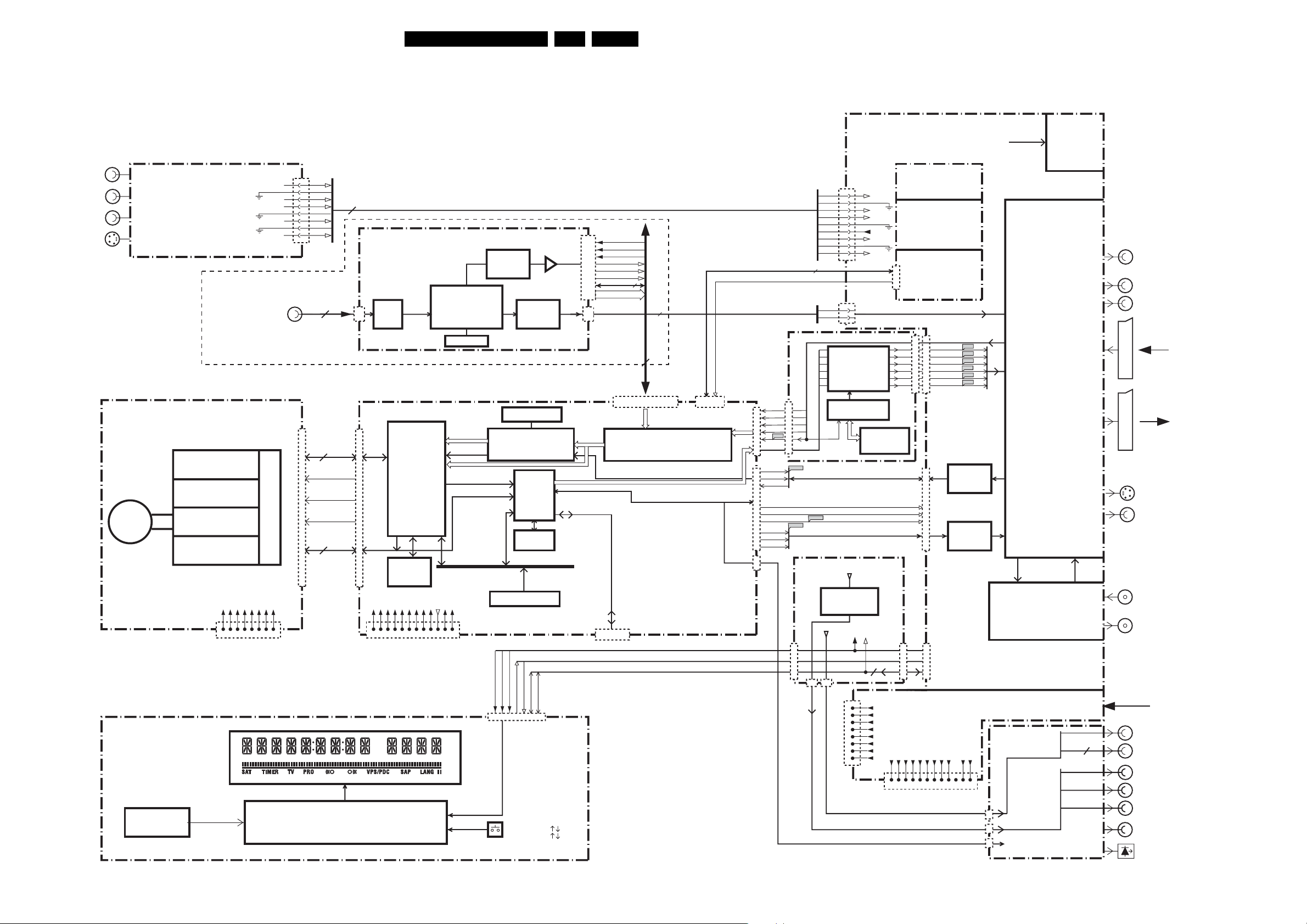
Block Diagrams, Waveforms, Wiring Diagram.
6. Block Diagrams, Waveforms, Wiring Diagram.
Overall Block Diagram Digital Board 1.5 Empress
EN 89DVDR70 & DVDR75/0x1 6.
AUDIO L
FRONT
Analog input
AUDIO R
CVBS
S-VIDEO
FRONT
Digital Video input
IEEE 1394
NOT USED IN DVDR70
DVD+RW ENGINE AV2
TRAY CONTROL
SERVO
DISC
LASER
READ
WRITE
AFCRI
AFCLI
CVBSFIN
CFIN
YFIN
1922
1402
1
2
3
4
5
7
8
9
4
DATA
&CONTROL
5
S2B
BE_FAN
RESETN_BE
BE_LOADN
7
FRONT-END I2S
1901
9
DVIO 1.8
PHY
DIGITAL PCB 1.5/1.9
1100,
1101
S2B
VSM
Stream
Manager
I2S
SDRAM
ANALOG AUDIO VIDEO
DV CODEC
LINK
SDRAM
VIDEO MPEG2
AUDIO
FRONT-END I2S or //
EMI BUS
WRAPPER
AUDIO DAC
SDRAM
MPEG VIDEO
ENCODING
EMPRESS
MPEG
AV
DECODER
+ HOST
(Sti5519)
2MB
SDRAM
1500
1501
DIG.VIDEO
ANAL.VIDEO
+3V3
+5V
+12V
DV_HS_OUT
DV_VS
DV_CLK
VSM_UART2
4
YUV(7:0)
1603
VIDEO INPUT
PROCESSING
4
60
(DATA+CONTROL+PSU)
DIG. AUDIO
1600
VSM_UART1
IRESET_DIG
BOARD 1/2
FOR DVDR80
ANALOG AUDIO L/R
EPG
1601
22
20
18
16
F4709
14
1602
AE_WCLK
20
AE_BCLK
21
AE_DATAI
18
3
4
SPDIF
2
MUTEN
7
AD_ACLK
9
AD_DATAO
11
AD_WCLK
12
AD_BCLK
14
DAOUT
2
1604
4
1
YUV-YCVBS/C
U24
1
3
5
7
9
AE_xCLK
AD_xCLK
A_R
A_B
A_G
A_C
DATA ACQUISITION
CVBS-RGB-Y/C-YUV
OSD GENERATION
A_YCVBS
AUDIO ENCODER I2S
AD_ACLK
AUDIO PCM I2S
EPG BOARD 2/2
FOR DVDR80
ANALOG BOARD
1942
1
AFCRI
2
3
AFCLI
4
CVBSFIN
5
6
8SW
7
CFIN
8
9
YFIN
1986
1960
1
ANA_R
4
ANA_L
OSD
INSERTION
EPG
PROCESSING
YUV
uP SUB BOARD
P50
CLOCK &
BACKUP
CONTROL
10
uP
U21
1947
F4712
D_CVBS
12
12
14
14
16
16
18
18
20
20
22
22
C_Y
D_C
D_R
D_G
F4714
F4716
F4718
F4720
F4722
D-B
1900
ADC
DAC
INTELLIGENT
CONTROL
INPUT/OUTPUT
PROCESSING &
SOURCE
SELECTION
FAN
DC
12V
OPTIONAL
AUDIO DIGITAL
FOR DVDR70/75
AUDIO L/R
SCART II
AUXI/O
SCARTI
TO TV
- I/O
S-VIDEO
CVBS
1234567
INFRA RED
EYE
DISPLAY & CONTROL
+3V3
8
+5V
GND
6
PSU
+4V6E
GND
124
GND
-5V
+12V
1000
8
FRONT PROCESSOR
+3V3
+3V3
+3V3
+3V3
GND
+12V
8
124
6
1234567
PSU
GND
GND
+5V
8191011
-5V
ION
GND
1900
12
FLASH 4/6MB
RS232
1901
SERVICE
U20
INT
POR_DC
5STBY
POWER
OPEN/CLOSE
PLAY
STOP
RECORD
LEFT/RIGHT
TRACK
CHANNEL
TV GUIDE
SCL
SDA
1910
+12Vstby
-Vgnstby
42853910
OSD
INSERTION
GLINK
PSU
U23
1933
1
2
3
4
5
6
ENGINE
7
8
I2C
IPOR_DC
2
+3V3
+5V
GND
+4V6E
GND
-5V
GND
+12V
1932
PSU
U26U25
1943
I2C
MULTI-MODE SOPS
+5V
GND
GND
+3V3
+12V
GND
9 101112
8
+3V3
+3V3
+3V3
1234567
DIGITAL PCB
GND
1923
1946
1920
-5V
TUNER
IO EXTENSION
BOARD
2
DAOUT
IR_OUT
GLINK_RXD
GLINK_TXD
ONLY FOR
DVDR80
2
ANTENNA INPUT
TV OUT
MAINS
AC
G LINK IR OUT
G LINK UART
Y
COMP. VIDEO
Cb
OUT
Cr
AUDIO DIGITAL
AUDIO OPTICAL
TR 17001_001
2021003
Page 90
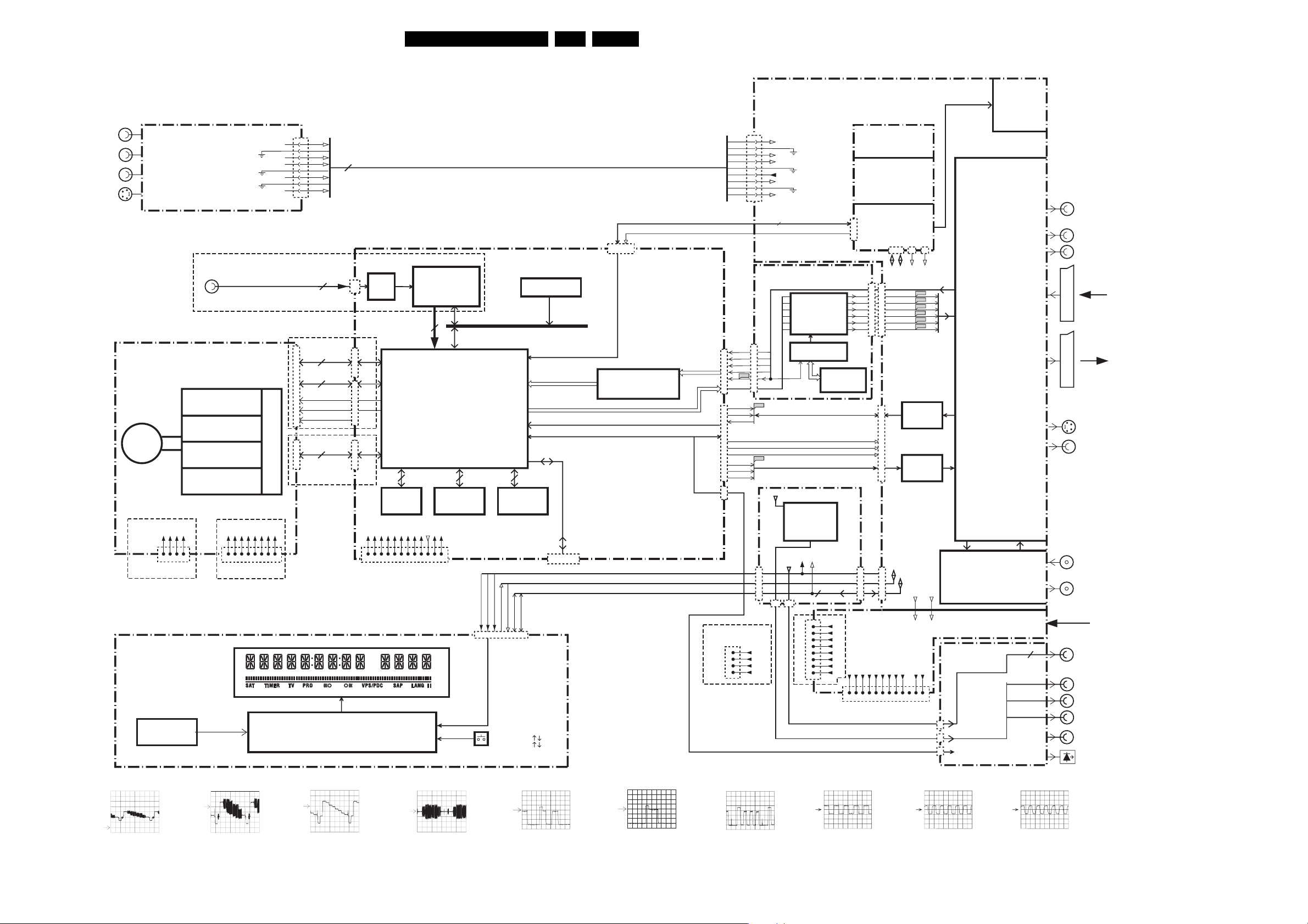
Block Diagrams, Waveforms, Wiring Diagram.
Overall Block Diagram Digital Board 2.1 Chrysalis
EN 90DVDR70 & DVDR75/0x1 6.
AUDIO L
FRONT
Analog input
AUDIO R
CVBS
S-VIDEO
ONLY FOR SETS WITH DV IN
Digital Video Input
IEEE 1394
DVD+RW ENGINE AV2/AV3
TRAY CONTROL
SERVO
DISC
LASER
READ
WRITE
+5V
GND
GND
1600-2
56 55 54
+12V
53
+3V3
+5V
GND
8
6
123456
FOR AV3 FOR AV2
PSU
DISPLAY & CONTROL
INFRA RED
EYE
+4V6E
GND
-5V
124
PSU
1922
AFCRI
AFCLI
CVBSFIN
CFIN
YFIN
1402
GND
+12V
7
8
1000
FRONT PROCESSOR
1
2
3
4
5
7
8
9
1203
4
FOR AV2
FRONT-END I2S
7
S2B UART
5
BE_DLOAD
RESET_BEn
BE_FAN
1600-1
40
ATAPI INTERFACE
FOR AV3
DATA
&CONTROL
9
ANALOG AUDIO VIDEO
DIGITAL PCB CHRYSALIS 2.1
PHY
1100
I2S
S2B
1105
1102
+3V3
+3V3
8
6
1234567
SDRAM
+3V3
+3V3
GND
124
PSU
LINK
CHRYSALIS PNX7100
MPEG 2, AC3 CODEC
I2C I2C
BOOT
EEPROM
GND
+5V
8191011
-5V
ION
GND
1500
12
+12Vstby
42853910
+12V
GND
-Vgnstby
PCI BUS
USRDATA
EEPROM
SCL
SDA
INT
POR_DC
5STBY
POWER
OPEN/CLOSE
PLAY
STOP
RECORD
LEFT/RIGHT
TRACK
CHANNEL
TV GUIDE
FLASH
DIG.VIDEO 656
ANALOG VIDEO
RS232
SERVICE
1910
1103
UART3: GATEWAY
IRESET_DIG
1104
VIDEO INPUT
PROCESSING
DIGITAL AUDIO
DIGITAL AUDIO
1942
1
2
3
4
5
6
7
8
9
1904
22
1
20
3
18
5
16
7
F4709
14
9
1900
A_xCLK
A_WCLK
20
A_BCLK
21
A_DAT
18
3
4
SPDIF
2
MUTEN
7
AD_ACLK
9
D_xCLK
D_DATAO
11
D_WCLK
12
D_BCLK
14
DAOUT
2
1901
U22
FOR IDE DRIVE
1934
4
+5V
3
GND
2
GND
1
+12V
ENGINE
ANALOG BOARD
AFCRI
AFCLI
CVBSFIN
8SW
CFIN
YFIN
6
1
EPG BOARD 1/2
YUV-YC-CVBS
OSD
INSERTION
U24
CVBS-RGB-Y/C
V_IN
U_IN
Y_IN
C_IN
DATA ACQUISITION
OSD GENERATION
CVBS_Y_IN
ONLY DVDR80
AUDIO ENCODER I2S
AUDIO PCM I2S
EPG
PROCESSING
EPG BOARD 2/2
YUV
ONLY DVDR80
OSD
INSERTION
PSU
I2C
GLINK
IPOR_DC
I2C, INT3
U23
1933
1
2
3
4
5
6
7
ENGINE
8
FOR
AV2
uP SUB BOARD
P50
CLOCK &
BACKUP
CONTROL
uP
10
U21
PSU
+3V3
MULTI-MODE SOPS
+5V
GND
4V6
GND
-5V
GND
+12V
+3V3
1234567
1932
1980
1986
I2C, INT
IPOR
1947
CVBS_OUT_B
12
12
Y_OUT_B
14
14
C_OUT_B
16
16
V_OUT_B
18
18
Y1_OUT_B
20
20
U_OUT_B
22
22
1900
U26U25
1943
GND
+3V3
+3V3
+3V3
+12V
DIGITAL PCB
IPOR, INT
GND
GND
91011128
1987
ION
I2C
+5V
1984
2 2
F4712
F4714
F4716
F4718
F4720
F4722
ADC
DAC
ION
GND
1923
1946
1920
STBY
INTELLIGENT
CONTROL
STBY
IO EXTENSION
BOARD
-5V
2
FAN
12V
FOR IDE
DRIVE
INPUT/OUTPUT
PROCESSING &
SOURCE
SELECTION
TUNER
DAOUT
ONLY FOR
DVDR80
DC
IR_OUT
GLINK_RXD
GLINK_TXD
AUDIO DIGITAL
FOR DVDR70/75
AUDIO L/R
SCART II
AUXI/O
SCARTI
TO TV
- I/O
S-VIDEO
CVBS
ANTENNA INPUT
TV OUT
MAINS
AC
G LINK IR OUT
3
G LINK UART
Y
COMP. VIDEO
Cb
OUT
Cr
AUDIO DIGITAL
AUDIO OPTICAL
A_YCVBS F4709 D_CVBS F4712
A: DC, 500mV/Div
10us/Div
A: DC, 200mV/Div
10us/Div
D_Y F4714
A: DC, 200mV/Div
10us/Div
D_C F4716
A: DC, 200mV/Div
10us/Div
D_R F4718
A: DC, 200mV/Div
10us/Div
D_G F4720
A: DC, 200mV/Div
10us/Div
D_B F4722
A: DC, 200mV/Div
10us/Div
AD_WCLK; AE_WCLK AD_BCLK; AE_BCLK
2V / div AC 10us / div
2V / div AC 200ns / div
AD_ACLK
2V / div AC 50ns / div
TR 10002_001
050503
Page 91
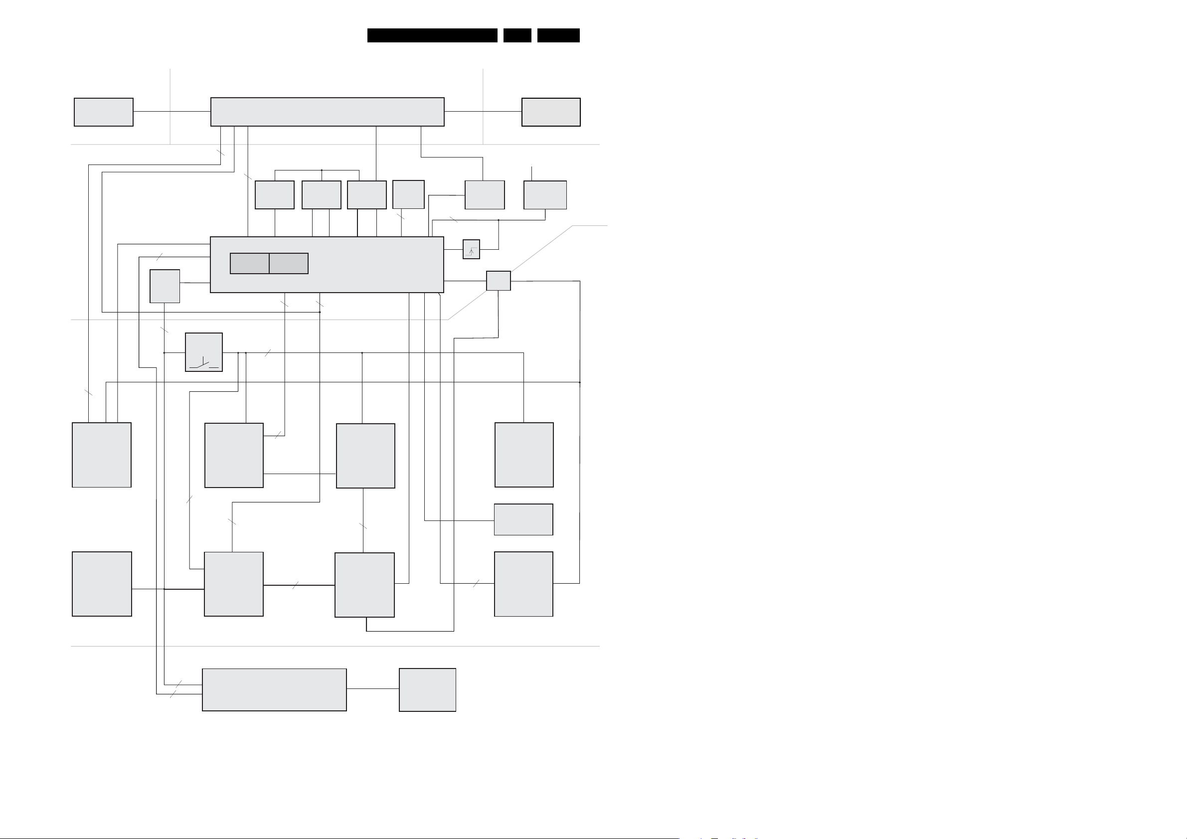
Block Diagrams, Waveforms, Wiring Diagram.
Control Block Diagram Analog Board, uP Board
DVIO-Board Digital Board Basic Engine
EN 91DVDR70 & DVDR75/0x1 6.
DVIO BE
I2S
FBIN
I2C
SWITCH
5SW
8
5
A_DATA
D_DATA
A_RDY
D_RDY
IRESET_DIG
int. RAM int. ROM
I2C_SW
ext. Latch ext. RAM ext. Flash
P-Subprint
LEVELSW
2
I2C
Level
Shifter
I2C 5V
INT, IPOR_DC
I2C 3,3V
2
Digital Board
A0-A7 A0-A7 WE
AD0-AD7
AD0-AD7
A8-A16
Central-P
TMP91CW12AF (3,3V Supply)
FBIN
5
5
2
AD0-AD7
WE
A8-A19
BE_FAN
BE_FAN
KILL
Fan
Control
only
IPOR
IPFAIL
>
1
=
AKILL
P50
2
P50in
P50out
Fan_off
2
INT
Reset
FOME
Analog Board
8
I2S
IPFAIL
ADC/DAC
(UDA1334BTS
UDA1361TS)
PWONSW
I2C_SW
Frontend
Video
5
SIF1
PSS
SB1
SFS_TS
AFC
AGC
I2C_SW
Frontend
Audio
(MSP)
I2C_SW
DataSlicer
(STV5348)
Sense 3V3STBY
Reset-IC
EEPROM
(M24C16)
I2C
Display Control Board
I2C_SW (for NAFTA only)
I2C
( for EUROPE
only)
2
I2C
2
INT
IPOR_DC
2
WU
WSFI
5
FBIN
P50
8SC2
IO
Video
(STV6618)
VSA1
VSA2
ASC1S
For EUROPE only
Front P
TMP87CH74F
RSA1
RSA2
2
STBY
3
Audio
IO
ASC1M for EUROPE only
ION
2
(HEF IC’S)
AKILL
Follow Me
Power
Supply
Display
TR 01019_001
130502
Page 92
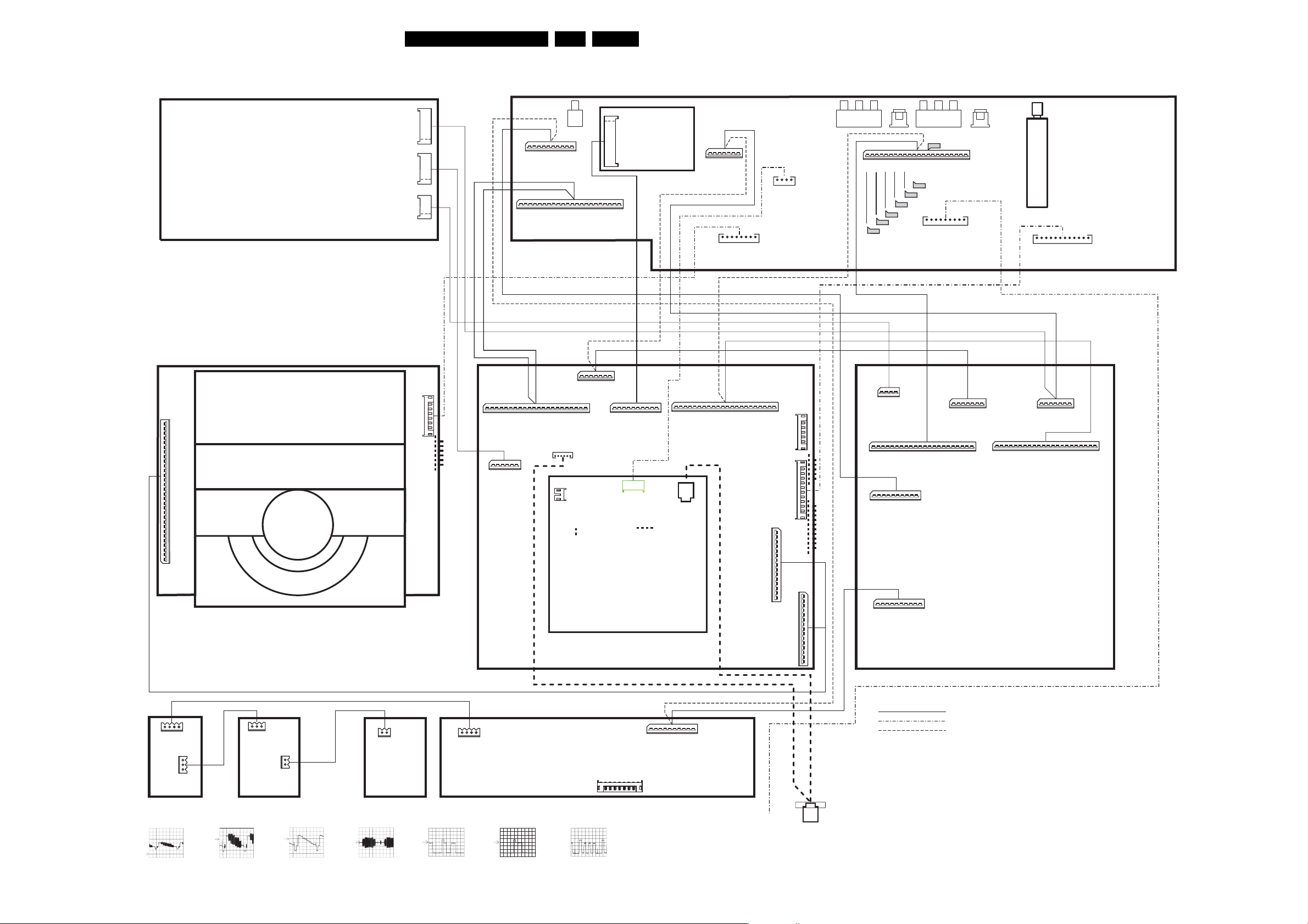
Block Diagrams, Waveforms, Wiring Diagram.
: ,
: ,
Wiring Diagram
IOE
(1005)
DVDR 80 EUROPE
DVDR 80
DVDR 75 APAC
DVDR 80
GNDA
GNDA
GNDA
GNDA
DAINOPT
DAINCOAX
DAOUT
GNDD
GLINK_RXD
GLINK_TXD
IR_OUT
EN 92DVDR70 & DVDR75/0x1 6.
7
V
6
5
D
U
4
1921
3
Y
2
1
6
N.C.
5
5V
D
4
3
1920
2
1
GND
4
D
3
2
1923
1
8026 .... 3103 601 0043.
8001 .... 3103 601 0019.
8010 .... 3103 601 0028.
8011 .... 3103 601 0029.
1943
22
GND
1mm
9
10
VGNSTBY
TEMP_SENSE
N.C.
DAOUT
N.C.
D
8
7
POR_DC
N.C.
654
INT
12VSTBY
1718192021
16
N.C.
D_IKILL
A
GND
GND
A
GND
D_PCMCLK
3
2
SDA
5VSTBY
GND
D_DATA0
1951
1
SCL
1112131415
D_WCLK
1mm
GNDD
1
2
FBIN
3
BE_FAN
WE
4
D
5
N.C.
D_RDY
6
1986
7
A_RDY
8
D_DATA
9
A_DATA
10
IRESET_DIG
789
GND
A_PCMCLK
65432
GND
GND
A_DAT
1mm
A_BCLK
A_WCLK
1
1900
8002 .... 3103 601 0020.
GND
8004 .... 3103 601 0022.
A
10
GND
D_BCLK
A
A
1mm
7
6
5
4
3
2
1946
V
Y
GND
GNDUGND
8007 .... 3103 601 0025.
1
2
1933
3V35VGND
1
GND
543
4V6
GND5NGND
JST-KR
4
321
1960
2mm
GND
GND
DVAR
DVAL
For DV-IN
2mm
JST-KR
7
8
6
12V
8005 .... 3103 601 0023.
1944
1949
1mm
21
22
D_B
D_C
D_G
D_R
GND
GND
GND
F4716
F4718
F4720
F4722
1941
A
F4709
D
8
9
7
13
14151617181920
12
10
11
D_Y
A_C
GND
GND
GND
GND
GND
D_CVBS
A_YCVBS
F4712
F4714
GND
AINFL
AINFR
6
5
A_G
GND
GND
CVBSFIN
432
GND
N.C.
A_B
CFINI
1948
1
1947
A_R
GND
2mm
987654321
JST-KR
1942
GND
YFIN
1932
TUNER
1
2
3V3
3V3
SPLITTER
3V3
3V3
ANALOG BOARD
(1001)
9876543
121110
5N
5V
ION
12V
GND
GND
GND
GND
2mm
JST-KR
8021 .... 3103 601 0038.
8013 .... 3103 601 0031.
8014 .... 3103 601 0020.
8016 .... 3103 601 0033.
8015 .... 3103 601 0032.
8006 .... 3103 601 0024.
A
1mm
7
1800
2mm
8
12V
7
GND
6
-5V
5
1402
1
GND
2
GND
3
N.C.
4
GND
5
IISDATA1
6
GND
7
SYNC
8
GND
9
FLAG
10
GND
11
BCLK
A
12
GND
13
IISDATA0
14
GND
15
WCLK
16
GND
17
RXD
18
GND
19
TXD
20
CPR
21
AIRQ
22
SUR
23
V4
24
GND
25
DLOAD
26
GND
27
N.C.
28
ARESETN
29
GND
30
GND
1mm
BASIC ENGINE
(1007)
GND
4
4V6
3
GND
2
5V
1
3V3
1901
8012 .... 3103 601 0040.
8020 .... 3103 601 0037.
1mm
1603
22
GNDD
1mm
AE_BCLK
AE_WCLK
654
5V
N.C.
GNDD
AE_DATA1
3
DAINOPT
DAINCOAX
1718192021
GNDD
2
DAOUT
A
16
GNDD
AE_ACLK
1
GNDD
131415
GNDD
AD_BCLK
101112
GNDD
AD_WCLK
AD_DATA0
9
8
GNDD
AD_ACLK
6
1201
7
65432
MUTEN
** +3V3
4
5
2
1
GNDD
1
N.C.
N.C.
** +5V
AD_SPDIF33
1
2
3
1200
LEDLED+
8019 .... 3103 601 0036.
654
DAC-B
GNDD
GNDD
3
GNDD
DAC-C
1602
DVIO
(1003)
2
1
GNDD
DAC-A/Y
1600
A
1mm
9
10
T1_RX
IRESET_DIG
VSM_UAR
1501
8
7
T1_TX
T1_CTSn
VSM_UAR
VSM_UAR
2
1
VOR
D
65432
ION
T1_RTSn
VSM_UAR
3
GND
GND
ANA_WE
4
VOL
1mm
1
GNDD
VIP_FB
BE_FAN
A
22
192021
18
Y_IN
C_IN
U_IN
V_IN
GNDD
GNDD
GNDD
1101
8003 .... 3103 601 0021.
A
789
65432
10
11121314151617
GNDD
GNDD
GNDD
GNDD
Y_OUT_B
CVBS_OUT_B
(1002)
GNDD
C_OUT_B
BCLK_CTL_SERVICE
GNDD
CVBS_Y_IN
DIGITAL BOARD
IISDATA1
IISDATA0
8018 .... 3103 601 0035.
GNDD
R_OUT_B
GND
GND
N.C.
GND
GND
SYNC
GND
FLAG
GND
BCLK
GND
GND
WCLK
GNDD
G_OUT_B
1101
1
CTS1P
GNDD
B_OUT_B
RTS1P
GNDD
GNDD
GNDD
GNDD
1mm
15
14
13
12
11
10
9
8
7
6
5
4
3
2
1
DLOAD
ARESETN
1601
RX1P
TX1P
N.C.
+3V3
+3V3
+3V3
+3V3
A
AIRQ
21
GNDD
20
GNDD
G_OUT_B
171819
GNDD
R_OUT_B
D
A
GNDD
C_OUT_B
1mm
7
1953
GND
GNDD
Y_OUT_B
A
6
543
V
GNDUGND
10111213141516
GNDD
GNDD
CVBS_Y_IN
CVBS_OUT_B
2
Y
GNDD
1
GND
789
6
2
543
1
1951
V_IN
Y_IN
U_IN
C_IN
GNDD
GNDD
GNDD
D
1mm
432
1
1970
1mm
1941
1940
22
1mm
GND
GLINK_RXD_CHAS
21
20
D_B
D_G
GND
GND
789
10
POR_DC
VGNSTBY
TEMP_SENSE
1mm
10
POR_DC
VGNSTBY
TEMP_SENSE
IR_OUT_CHAS
GLINK_TXD_CHAS
D_C
D_R
D_Y
GND
GND
D
65432
INT
GND
GND
5VSTBY
12VSTBY
A
789
65432
INT
GND
GND
5VSTBY
12VSTBY
D
9
13141516171819
101112
GND
GND
GND
D_CVBS
A_YCVBS
1
SCL
SDA
1
SCL
SDA
SERVICE
7
+5V
6
5
4
3
JST-KR
2
1
2mm
1901
12
-5V
11
8008 .... 3103 601 0006.
10
ION
9
+5V
8
7
6
5
JST-KR
4
3
2mm
2
1
1900
1100
1mm
GND
15
RXD
14
GND
13
TXD
12
CPR
11
10
A
9
SUR
8
V4
7
GND
6
5
GND
N.C.
4
3
2
GND
1
GND
8
GND
1950
7
A_C
1mm
7
6
Y
GND
65432
A_G
GND
GND
A
5
432
GNDUGND
A_B
GND
V
1
A_R
EPG
(1006)
1
GND
1952
1mm
22
B_OUT_B
8017 .... 3103 601 0034.
8009 .... 3103 601 0027.
8022 .... 3103 601 0016.
2mm
3
2
8023 .... 3103 601 0017.
1
1940
+12VSTBY
TRAY_LED1
TRAY_LED2
TRAY_LED2
+12VSTBY
Traylight
left
JST DA
1941
1
2
JST DA
2mm
8024 .... 3103 601 0018.
2
1
JST DA
1950
+12VSTBY
TRAY_LED2
Traylight
right
2mm
342
1
2mm
1911
JST DA
K1
TRAY_LED
+12VSTBY
GND
CONTROL-PANEL
0
3UH000
1922
AFCRI_FC
GND_FC
AFCLI_FC
CVBSFIN_FC
GND_FC
342
1
2mm
1930
JST DA
K1
GND
TRAY_LED
1931
+12VSTBY
1
TRAY_LED1
2
+12VSTBY
3
TRAY_LED2
JST DA
2mm
2000-03-10
KEYPRINT
8SW_FC
CFIN_FC
678954321
YFIN_FC
GND_FC
1910
2mm
JST-KR
A
A
1mm
9
7
8
6
543
2
GND
5VSTBY
1
INT
GND
POR_DC
12VSTBY
VGNSTBY
TEMP_SENSE
10
SDA
SCL
FFC-Cable
Cable Tree assy
FFC-Cable only for DVDR 70/75
A_YCVBS F4709
A:
DC, 500mV/Div
10us/Div
D_CVBS F4712
A: DC
, 200mV/Div
10us/Div
D_Y F4714
A: DC, 200mV/Div
10us/Div
D_C F4716
A: DC, 200mV/Div
10us/Div
D_R F4718 D_G F4720
A: DC, 200mV/Div
10us/Div
A: DC, 200mV/Div
10us/Div
D_B F4722
A: DC, 200mV/Div
10us/Div
18
130 210
1101
DV IN
TR 06005_002
110303
Page 93
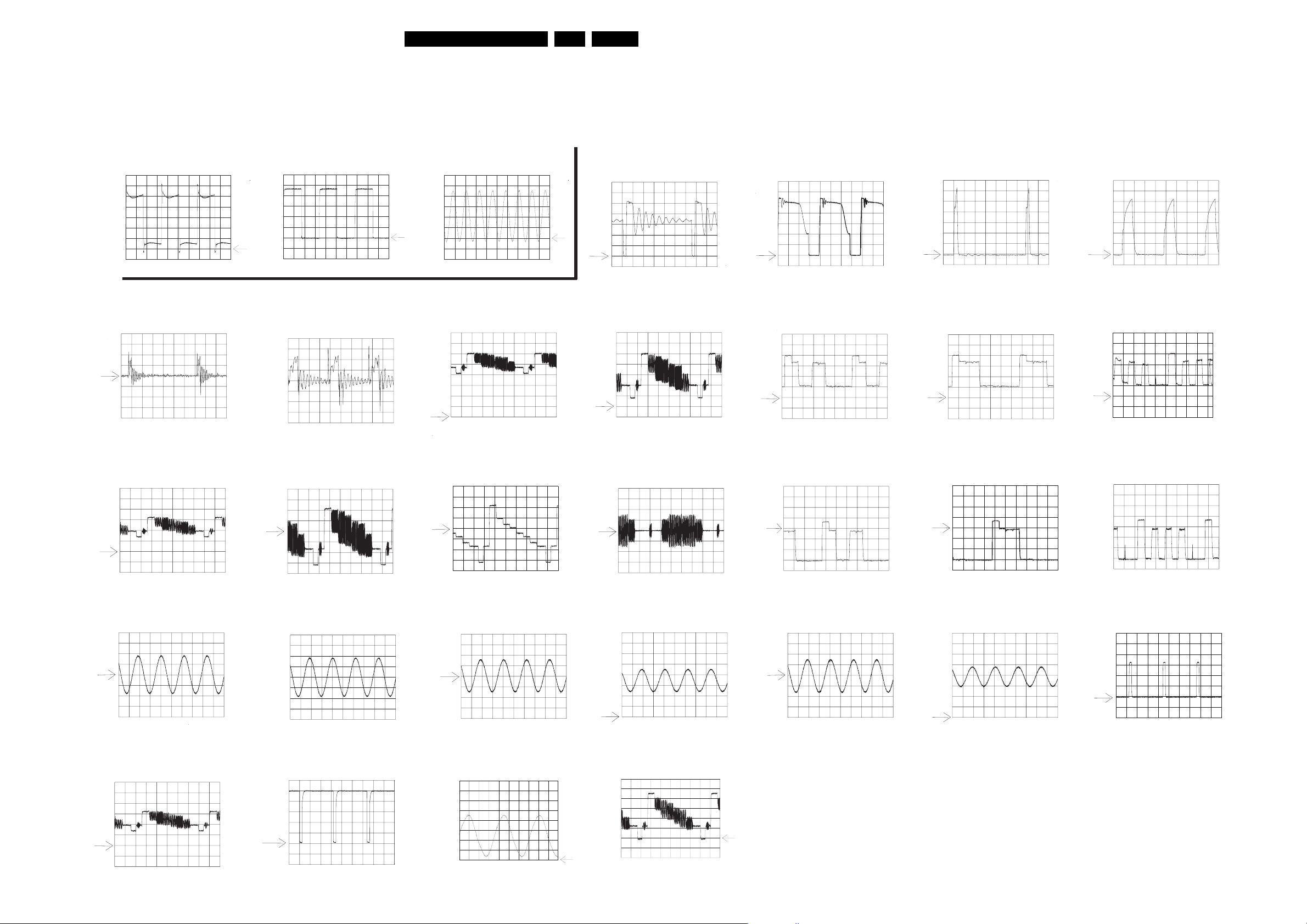
Waveforms
Block Diagrams, Waveforms, Wiring Diagram.
Waveforms Display Board
EN 93DVDR70 & DVDR75/0x1 6.
Waveforms Analog Board
7106/7108-Emitter
A: DC, 2 V/Div, 10us/Div
I324 VSource (Standby)
A: DC, 50mV/Div
5us/Div
A_CVBS I405
IC7103-19
A: DC, 1 V/Div, 10us/Div
I324 VSource (no disc loaded)
A: DC, 50mV/Div
2us/Div
D_CVBS F4712
IC7103-8
A: DC, 1 V/Div, 100ns/Div
F723 VFV I723
A: DC, 500mV/Div
10us/Div
D_Y F4714
F327 VDrain (Standby)
A: DC, 100V/Div
5us/Div
E465
A: DC, 500mV/Div
10us/Div
D_C F4716
F327 VDrain (no disc loaded)
A: DC, 100V/Div
2us/Div
E461
A: DC, 500mV/Div
10us/Div
D_R F4718
I324 VGate (Standby)
A: DC, 1V/Div
5us/Div
E462
A: DC, 500mV/Div
10us/Div
D_G F4720
I324 VGate (no disc loaded)
A: DC, 2V/Div
2us/Div
E463
A: DC, 500mV/Div
10us/Div
D_B F4722
A: DC, 500mV/Div
10us/Div
I502/I504
A: DC, 500mV/Div
500us/Div
A_CVBS F8008
A: DC, 500mV/Div
A: DC, 200mV/Div
10us/Div
I517/I518
A: DC, 500mV/Div
500us/Div
I818
A: DC, 1 V/Div
A: DC, 200mV/Div
10us/Div
F501/F502
A: DC, 500mV/Div
500us/Div
I994
A: DC, 1 V/Div
20ns/Div
A: DC, 200mV/Div
10us/Div
I014/I032
A: DC, 500mV/Div
500us/Div
I989
A: DC, 200mV/Div
10us/Div
A: DC, 200mV/Div
10us/Div
ARDAC/ALDAC F010/F011
A: DC, 500mV/Div
500us/Div
A: DC, 200mV/Div
10us/Div
I623
A: DC, 1 V/Div
500us/Div
A: DC, 200mV/Div
10us/Div
SYNC F843
A: DC, 500mV/Div
10us/Div
TR 070018_001
200303
Page 94
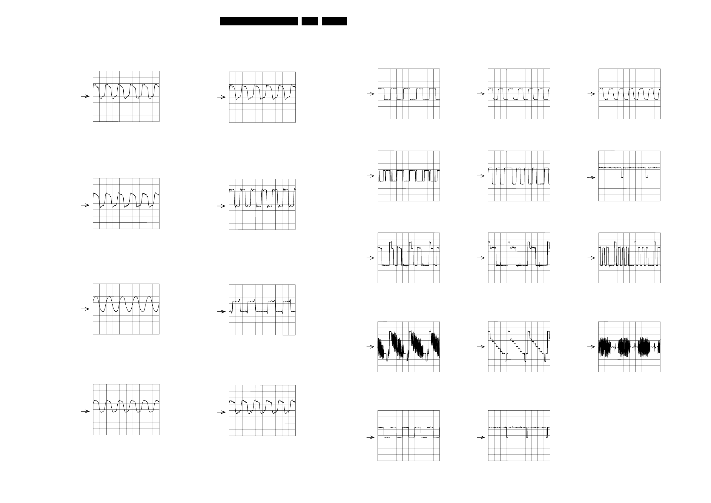
Block Diagrams, Waveforms, Wiring Diagram.
EN 94DVDR70 & DVDR75/0x1 6.
Waveforms Digital Board 1.5
Sysclk_VSM
2V / div DC 20ns / div
27M_clk_PS
Sysclk_5505
2V / div DC 20ns / div
acc_aclk_pll
Waveforms Digital Board 1.5
AD_WCLK; AE_WCLK
2V / div AC 10us / div 2V / div AC 200ns / div
AD_DATAO; AE_DATAO; AE_DATAIAD_DATAO; AE_DATAO; AE_DATAI
2V / div AC 5us / div
AD_BCLK; AE_BCLK
AD_SPDIF
2V / div AC 250ns / div
AD_ACLK
2V / div AC 50ns / div
I401 VIP_VS
2V / div DC 5ms / div
2V / div DC 20ns / div
EMI_PROCCLK
2V / div DC 10ns / div
VIP_ICLK
2V / div DC 50ns / div
DSP_clk
2V / div DC 10ms / div
VSM_M_CLK
R_OUT
200mV / div AC 20us / div
CVBS_OUT
200mV / div AC 20us / div
G_OUT
200mV / div AC 20us / div
Y_OUT
200mV / div AC 20us / div
B_OUT
200mV / div AC 20us / div
C_OUT
200mV / div AC 20us / div
2V / div DC 20ns / div
2V / div DC 20ns / div
CL 16532145_053.eps
031201
VSYNC
2V / div DC 20ms / div
HSYNC
2V / div DC 20ms / div
CL 16532145_054.eps
031201
Page 95
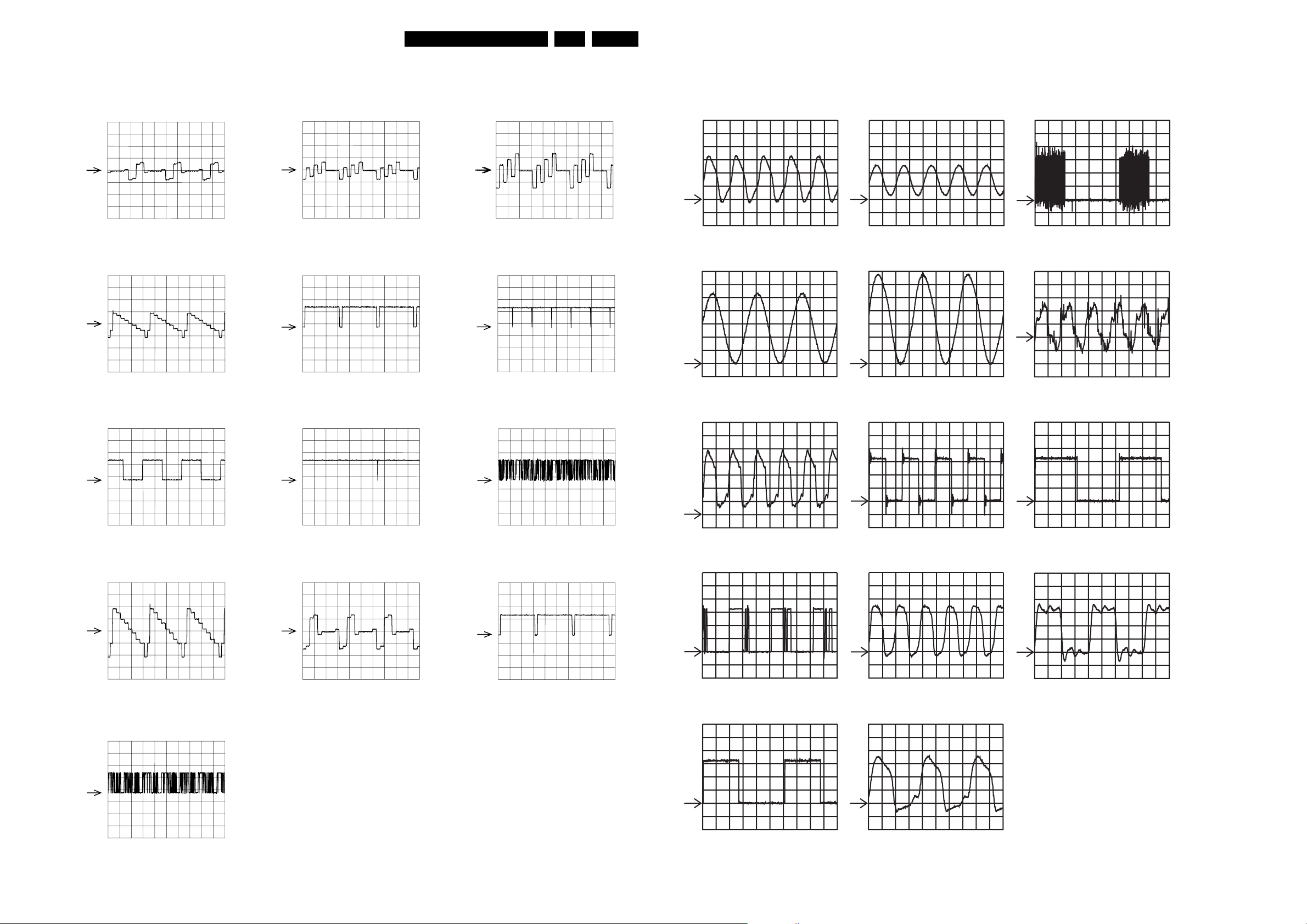
Block Diagrams, Waveforms, Wiring Diagram.
EN 95DVDR70 & DVDR75/0x1 6.
DAC-B
500mV / div AC 10us / div
DAC-C
500mV / div AC 10us / div
Waveforms Digital Board 1.5
DAC-A/Y
500mV / div AC 10us / div
HS_IN
2V / div DC 20us / div
Cr-signal
500mV / div AC 10us / div
VSOUT
2V / div DC 10ms / div
Waveforms DVIO
F410
A: DC, 1 V/Div, 20ns/Div A: DC, 1 V/Div, 20us/Div
F800
A:
DC, 500mV/Div
, 50ns/Div
A: DC, 1 V/Div, 20ns/Div
A: DC, 1 V/Div, 500ns/Div
F411
F801
F400/F401
F527
A: DC, 2V/Div, 20ns/Div
FRAME_IN
2V / div DC 10ms / div
Y-signal
500mV / div AC 10us / div
Y_OUT; Cr_OUT; Cb_OUT
VS_IN
2V / div DC 10ms / div
Cb-signal
500mV / div AC 10us / div
YUV_IN
2V / div DC 10ms / div
HSOUT
2V / div DC 10us / div
F529
A: DC, 1 V/Div, 20ns/Div
F536
A: DC, 1 V/Div, 5us/Div
F609
F551
A: DC, 1 V/Div, 200ns/Div
F603
A: DC, 1 V/Div, 20ns/Div
F620
F552
A: DC, 1 V/Div, 5us/Div
F610
A: DC, 1 V/Div, 20ns/Div
2V / div DC 20us /div
CL 16532145_055.eps
031201
A: DC, 1 V/Div, 200Us/Div
TR 06055_001
110203
A: DC, 1 V/Div, 10ns/Div
Page 96
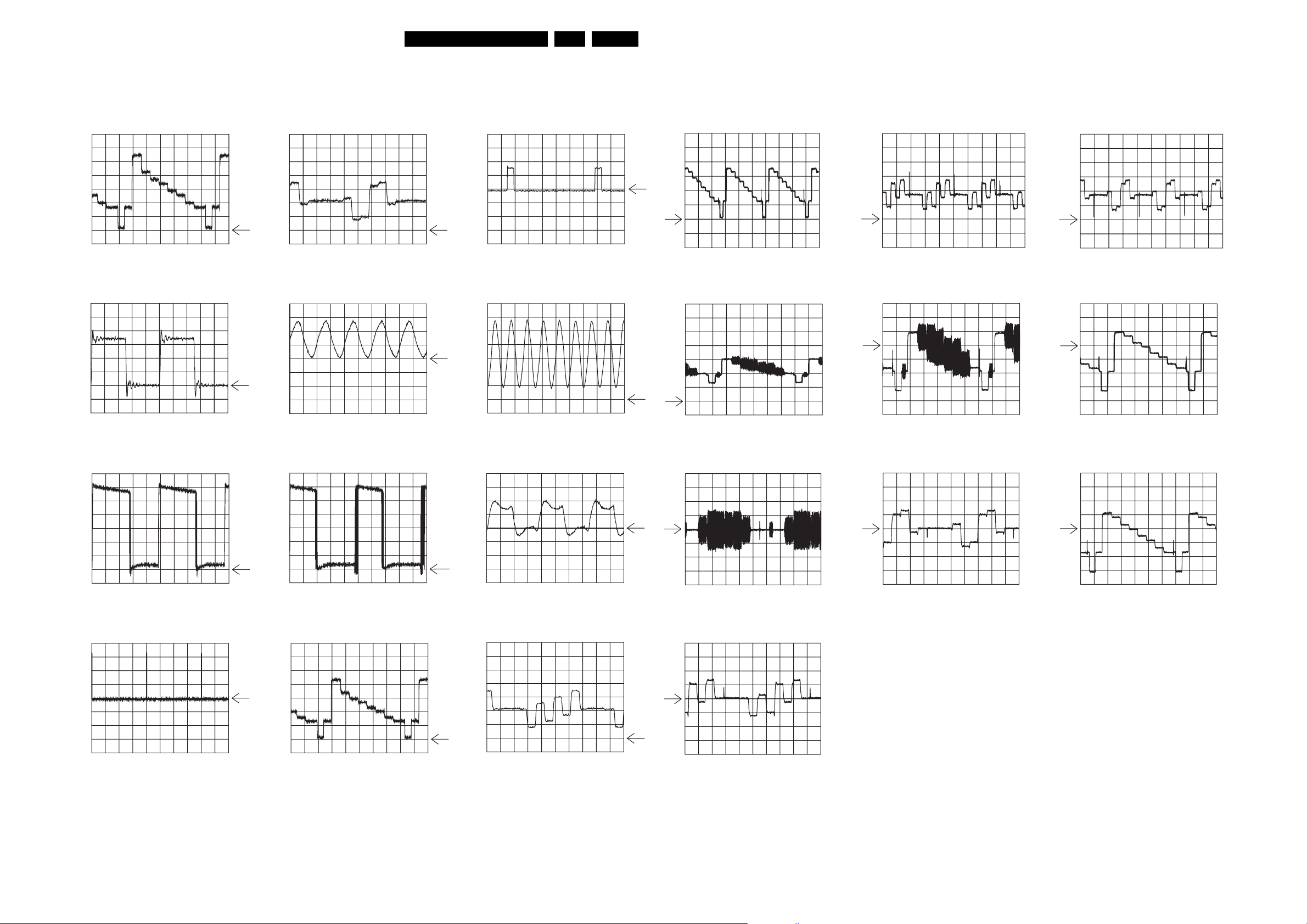
Block Diagrams, Waveforms, Wiring Diagram.
EN 96DVDR70 & DVDR75/0x1 6.
Waveforms Digital Board Chrysalis 2.1
IC7703 pin 34
A: DC, 200mV/Div, 5us/Div
IC7402 pin 3, F405
A: DC, 1 V/Div, 50ns/Div
0V
IC7703 pin 36
A: DC, 200mV/Div, 5us/Div
IC7200 pin 60, F203
A: DC, 1 V/Div, 20ns/Div
HS_IN
A: DC, 2 V/Div, 10us/Div
X1001
A: DC, 500mV/Div, 2us/Div
Y 1704-2
A: DC, 500mV/Div
10us/Div
A_YCVBS 1904-14
A: DC, 500mV/Div
10us/Div
PB 1704-4
A: DC, 500mV/Div
10us/Div
D_YCVBS 1904-11
A: DC, 200mV/Div
10us/Div
PR 1704-6
A: DC, 500mV/Div
10us/Div
D_Y 1904-9
A: DC, 200mV/Div
10us/Div
IC7501 pin 5
A: DC, 2 V/Div, 1us/Div
VS_IN
A: DC, 1 V/Div, 5ms/Div
IC7501 pin 6
A: DC, 2 V/Div, 1us/Div
1704-2, F1702
A: DC, 500mV/Div, 5us/Div
IC7703 pin 25
A: DC, 2 V/Div, 10ns/Div
IC7703 pin 32
A: DC, 200mV/Div, 5us/Div
D_C 1904-7
A: DC, 200mV/Div
10us/Div
D_UB 1904-1
A: DC, 200mV/Div
10us/Div
D_VR 1904-5
A: DC, 200mV/Div
10us/Div
D_YG 1904-3
A: DC, 200mV/Div
10us/Div
TR 09014_001
220403
Page 97
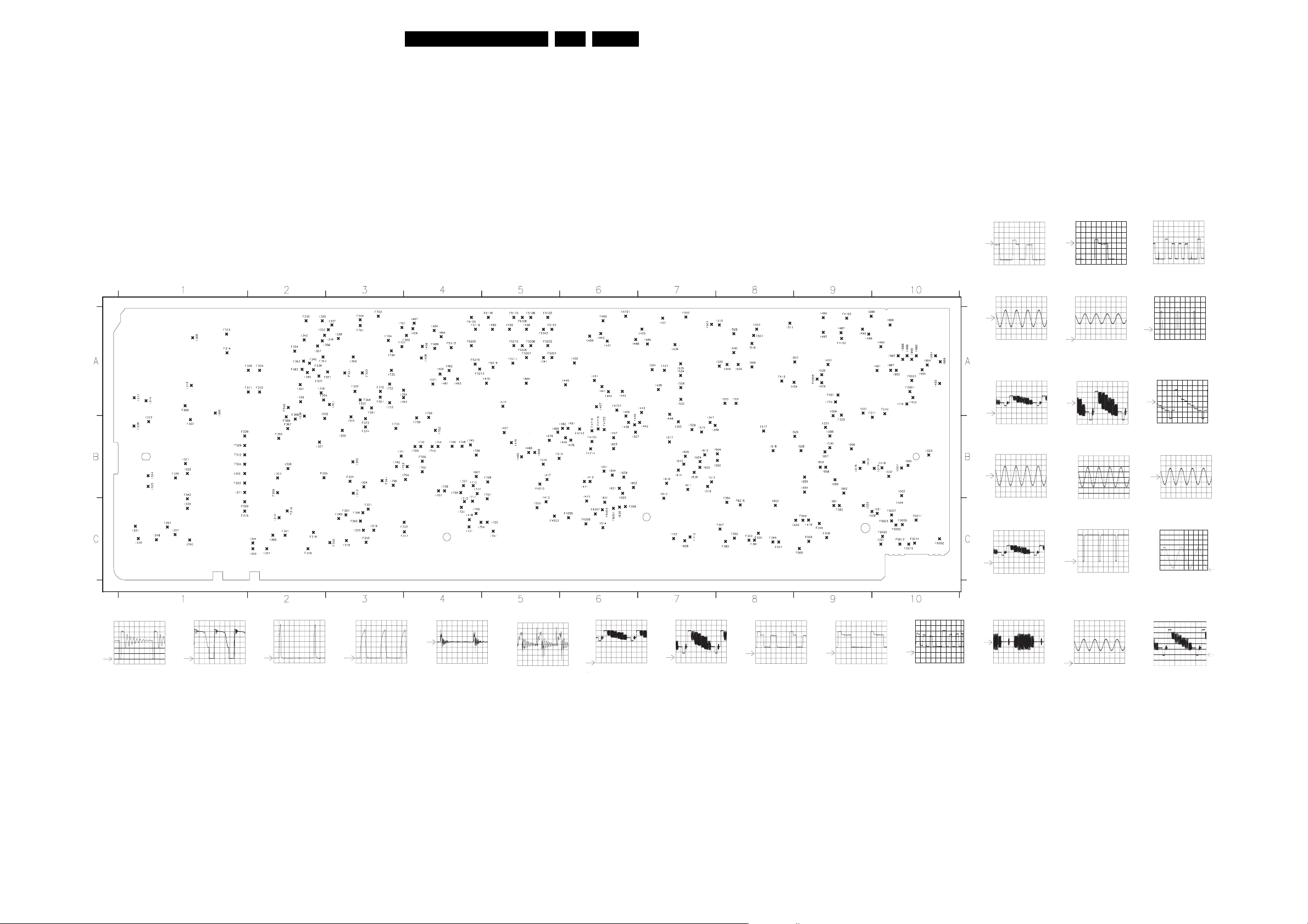
Block Diagrams, Waveforms, Wiring Diagram.
Test points overview Analog Board
EN 97DVDR70 & DVDR75/0x1 6.
F0001 A10
F0002 C10
F0003 C10
F0005 C10
F0007 C10
F0009 C10
F0010 C9
F0011 C10
F0012 C10
F0014 C10
F0016 C10
F0021 A10
F006 C9
F007 C8
F008 C9
F009 C9
F010 A10
F011 B10
F300 A3
F301 A3
F302 A4
F304 B1
F305 B2
F306 A1
F307 B1
F308 A2
F309 A2
F310 A2
F311 A2
F312 B1
F313 A1
F314 A1
F315 C1
F316 C2
F317 C4
F318 C2
F319 C2
F320 C1
F321 C3
F322 C4
F323 B1
F324 B3
F325 A9
F326 B2
F328 B1
F329 B1
F331 A3
F333 A3
F334 A2
F335 A2
F336 A2
F337 A2
F338 B1
F339 B1
F340 A2
F341 B3
F342 C1
F343 A2
F344 C9
F346 A2
F347 C8
F348 C8
F349 C3
F350 C3
F351 A3
F352 C8
F353 C8
F354 A2
F355 C3
F356 C3
F357 C3
F358 C6
F359 C8
F360 C3
F361 C2
F362 A2
F363 A2
F364 A3
F366 B2
F367 B2
F368 B2
F369 B2
F371 A3
F372 A3
F373 B3
F374 B3
F381 C8
F382 C9
F383 C8
F384 C8
F401 A9
F4102 A9
F4103 A9
F412 A8
F4203 C5
F4205 C6
F4207 C6
F4209 C6
F4210 B5
F4505 A9
F4707 A6
F4712 B6
F4714 B6
F4716 B6
F4718 B6
F4720 B6
F4721 A6
F4722 B6
F485 A6
F499 A4
F501 A7
F502 A7
F504 A3
F5101 A5
F5102 A5
F5103 A5
F5106 A5
F5108 A5
F5110 A5
F5113 A4
F5116 A5
F5119 A4
F5120 A4
F5201 A5
F5202 A5
F5203 A5
F5206 A5
F5207 A5
F5208 A5
F5210 A5
F5211 A5
F5213 A4
F5215 A5
F5216 C8
F5219 A4
F5220 A4
F6001 C6
F6002 C10
F6004 C6
F701 A3
F702 B4
F703 A3
F704 A3
F707 A3
F708 B5
F709 B4
F710 B3
F713 C7
F913 B5
F950 C9
I001 C10
I002 B10
I004 C10
I005 B10
I006 B9
I007 B10
I008 B9
I009 B9
I013 B9
I014 B10
I015 B9
I018 B10
I019 B10
I020 A9
I021 B9
I022 C9
I023 B10
I029 C10
I030 B9
I031 C10
I032 B10
I036 A9
I300 A1
I301 A3
I303 B2
I304 B3
I305 B3
I306 A1
I307 C1
I308 B2
I309 B3
I310 C2
I311 B1
I312 B1
I313 B3
I314 A1
I315 B3
I316 A1
I317 A1
I318 C3
I319 C3
I320 C3
I321 B1
I322 B1
I323 A3
I324 B1
I325 B1
I326 A2
I327 B2
I329 A2
I330 C1
I331 C1
I332 B2
I333 A3
I334 A2
I335 C1
I336 B2
I337 A3
I338 A3
I339 A2
I340 C1
I341 A5
I342 A2
I343 C1
I344 C2
I345 A2
I346 A3
I347 B7
I348 C1
I349 B7
I350 C2
I351 C2
I352 B7
I353 A3
I354 A3
I355 C2
I356 A2
I357 A2
I361 A2
I402 A6
I405 A10
I406 A4
I407 A4
I408 A4
I409 A4
I411 B6
I412 B6
I413 C5
I414 A5
I415 C6
I416 B5
I417 B5
I418 C4
I419 C9
I420 C9
I424 A4
I428 A7
I429 A9
I431 A7
I433 A7
I434 A7
I437 A6
I438 B6
I439 A6
I440 A6
I441 A6
I442 B7
I443 A7
I444 A6
I445 A6
I446 B6
I447 B6
I448 A7
I449 A6
I451 A6
I453 A9
I454 A9
I456 B6
I457 B5
I458 A5
I459 A5
I460 A5
I461 A4
I462 A4
I463 A4
I464 A4
I465 A4
I466 B5
I467 A6
I468 B6
I469 B5
I470 B5
I476 A5
I478 B6
I479 B5
I481 B6
I482 B6
I483 B5
I484 A5
I485 A7
I486 A6
I487 A9
I488 A9
I489 A9
I490 A10
I491 A10
I492 A9
I493 A9
I501 A8
I502 B8
I503 A8
I504 B8
I505 C5
I506 B5
I507 A9
I508 A7
I509 A8
I510 A8
I511 A8
I513 B7
I514 C6
I515 B7
I516 B7
I517 B8
I518 B8
I519 A8
I520 A8
I521 A4
I523 A7
I524 A7
I525 B9
I526 B9
I527 B6
I611 B7
I612 B7
I613 C7
I614 B7
I615 B7
I616 B7
I617 B7
I620 B6
I621 B6
I623 B6
I624 B7
I625 B7
I630 C6
I631 C6
I701 A3
I702 B4
I703 B4
I704 B4
I706 B3
I528 B7
I529 A8
I530 A8
I531 A8
I532 A7
I533 A8
I534 A7
I535 A7
I539 A8
I540 A8
I601 B6
I602 C8
I603 B6
I604 B6
I605 B7
I607 B4
I608 C7
I609 B6
I610 B7
I707 B4
I708 B4
I709 B4
I711 C4
I712 B4
I713 C4
I715 A9
I716 A10
I717 B4
I721 C4
I723 C7
I724 C5
I725 C5
I726 B4
I727 B4
I728 B4
I729 B4
I730 B4
I731 C4
I732 A3
I733 A3
I734 A3
I735 A3
I739 B4
I741 B3
I742 B3
I743 B4
I744 B4
I745 B4
I746 B4
I748 B4
I749 C4
I751 C5
I754 C4
I951 C9
I952 B9
I954 B9
I955 B9
I956 B9
I957 B9
I958 B9
I959 B9
I987 A10
I988 A10
I989 A10
I990 A10
I991 A10
I992 A10
I993 A10
I994 A10
I995 A10
I996 A9
I997 A10
I998 A10
I999 A10
D_R F4718
A: DC, 200mV/Div
10us/Div
ARDAC/ALDAC F010/F011
A: DC, 500mV/Div
500us/Div
A_CVBS I405
A: DC, 500mV/Div
10us/Div
I502/I504
A: DC, 500mV/Div
500us/Div
A_CVBS F8008
D_G F4720
A: DC, 200mV/Div
10us/Div
I623
A: DC, 1 V/Div
500us/Div
D_CVBS F4712
A: DC, 200mV/Div
10us/Div
I517/I518
A: DC, 500mV/Div
500us/Div
I818
D_B F4722
A: DC, 200mV/Div
10us/Div
SYNC F843
A: DC, 500mV/Div
10us/Div
D_Y F4714
A: DC, 200mV/Div
10us/Div
F501/F502
A: DC, 500mV/Div
500us/Div
I994
F327 VDrain (Standby)
A: DC, 100V/Div
5us/Div
F327 VDrain (no disc loaded)
A: DC, 100V/Div
2us/Div
I324 VGate (Standby)
A: DC, 1V/Div
5us/Div
I324 VGate (no disc loaded)
A: DC, 2V/Div
2us/Div
I324 VSource (Standby)
A: DC, 50mV/Div
5us/Div
I324 VSource (no disc loaded)
A: DC, 50mV/Div
2us/Div
F723 VFV I723
A: DC, 500mV/Div
10us/Div
E465
A: DC, 500mV/Div
10us/Div
E461
A: DC, 500mV/Div
10us/Div
E462
A: DC, 500mV/Div
10us/Div
TR 07002_001
200303
E463
A: DC, 500mV/Div
10us/Div
A: DC, 500mV/Div
10us/Div
D_C F4716
A: DC, 200mV/Div
10us/Div
A: DC, 1 V/Div
20us/Div
I014/I032
A: DC, 500mV/Div
500us/Div
A: DC, 1 V/Div
20ns/Div
I989
A: DC, 200mV/Div
10us/Div
Page 98
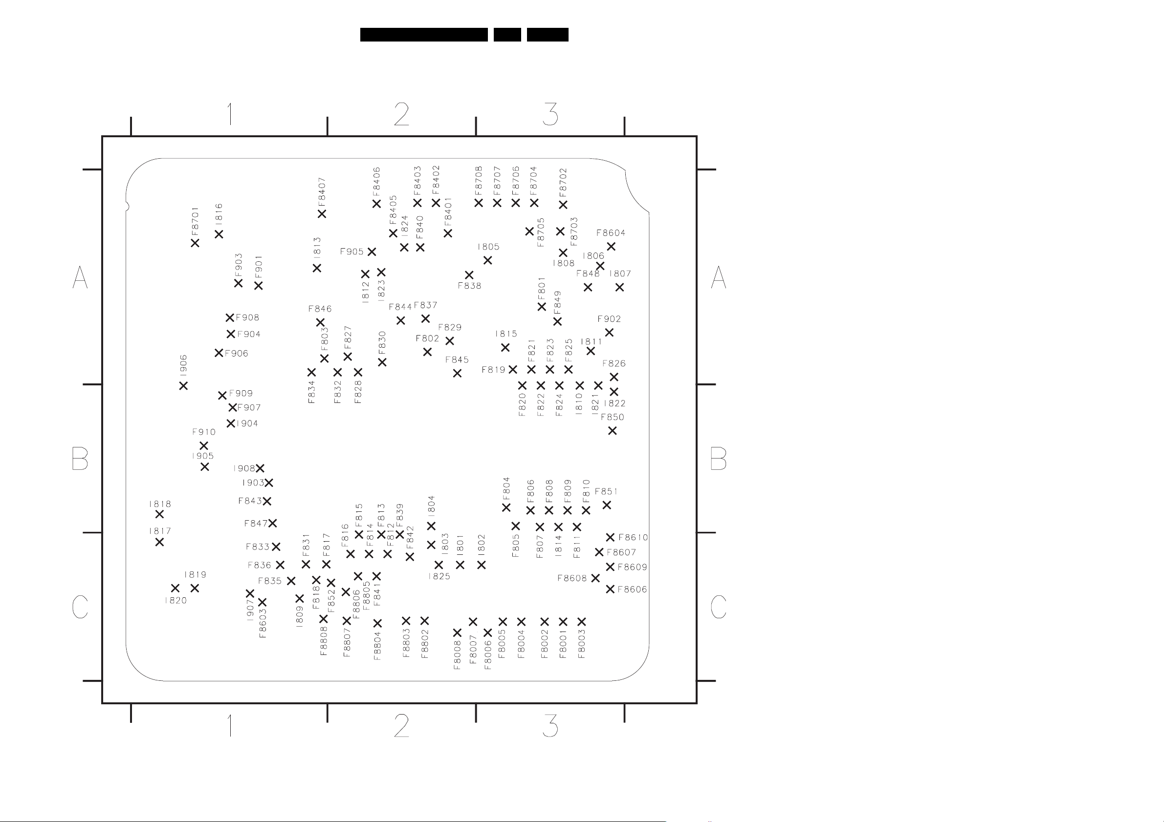
Block Diagrams, Waveforms, Wiring Diagram.
Test points overview UP Sub Board
EN 98DVDR70 & DVDR75/0x1 6.
F8001 C3
F8002 C3
F8003 C3
F8004 C3
F8005 C3
F8006 C3
F8007 C2
F8008 C2
F801 A3
F802 A2
F803 A1
F804 B3
F805 B3
F807 B3
F812 C2
F813 C2
F814 C2
F815 C2
F816 C2
F817 C1
F818 C1
F819 A3
F820 B3
F821 A3
F822 B3
F823 A3
F824 B3
F825 A3
F826 A3
F827 A2
F828 A2
F829 A2
F830 A2
F831 C1
F832 A2
F833 C1
F834 A1
F835 C1
F836 C1
F837 A2
F838 A2
F839 C2
F840 A2
F8401 A2
F8402 A2
F8403 A2
F8406 A2
F8407 A1
F841 C2
F842 C2
F843 B1
F844 A2
F845 A2
F846 A1
F847 B1
F848 A3
F849 A3
F850 B3
F851 B3
F852 C2
F8603 C1
F8604 A3
F8606 C3
F8607 C3
F8608 C3
F8609 C3
F8610 C3
F8701 A1
F8702 A3
F8703 A3
F8704 A3
F8705 A3
F8706 A3
F8707 A3
F8708 A3
F8802 C2
F8803 C2
F8804 C2
F8805 C2
F8806 C2
F8807 C2
F8808 C1
F901 A1
F902 A3
F903 A1
F904 A1
F905 A2
F906 A1
F907 B1
F908 A1
F909 B1
F910 B1
I801 C2
I802 C3
I803 C2
I804 B2
I805 A3
I806 A3
I807 A3
I808 A3
I809 C1
I810 B3
I811 A3
I812 A2
I813 A1
I814 B3
I815 A3
I816 A1
I817 C1
I818 B1
I819 C1
I820 C1
I821 B3
I822 B3
I823 A2
I824 A2
I825 C2
I903 B1
I904 B1
I905 B1
I906 B1
I907 C1
I908 B1
TR 06058_001
250203
Page 99
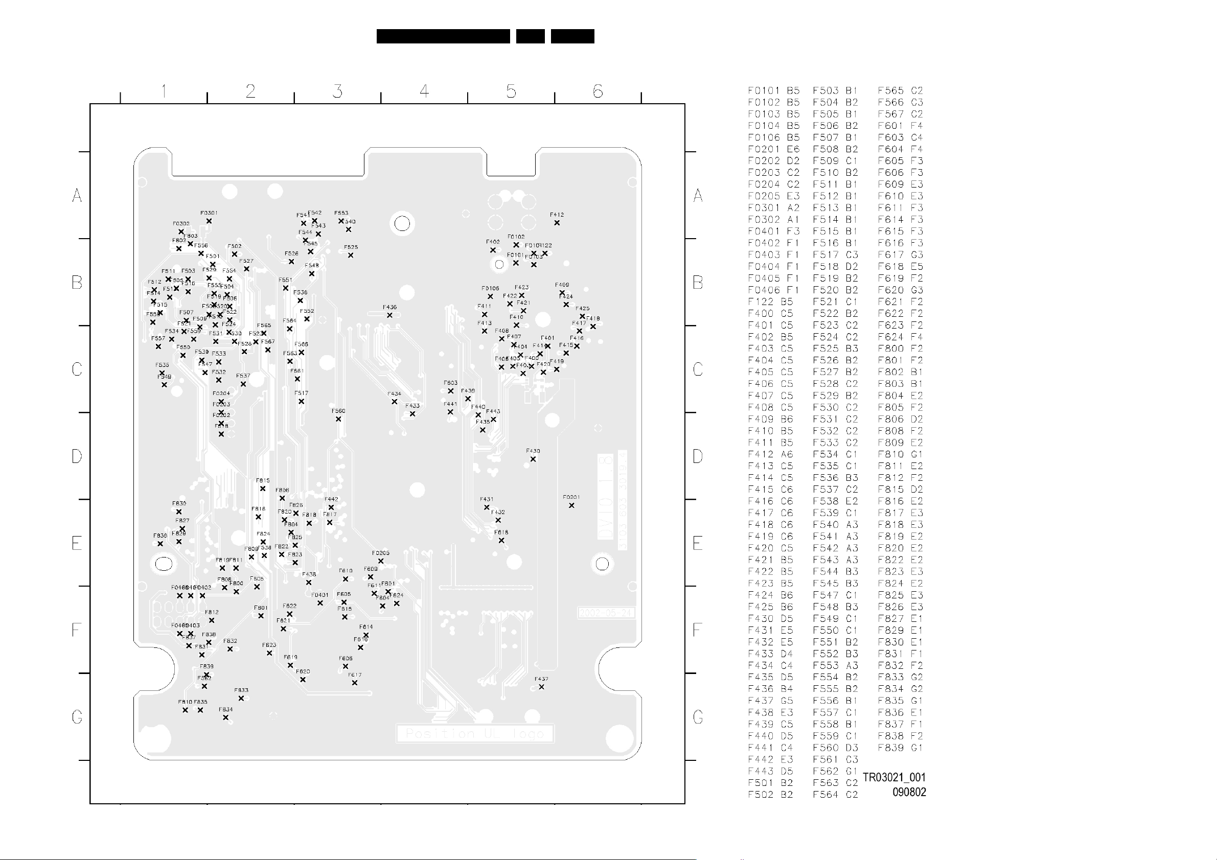
Block Diagrams, Waveforms, Wiring Diagram.
Test points overview DIVIO Board
EN 99DVDR70 & DVDR75/0x1 6.
Page 100
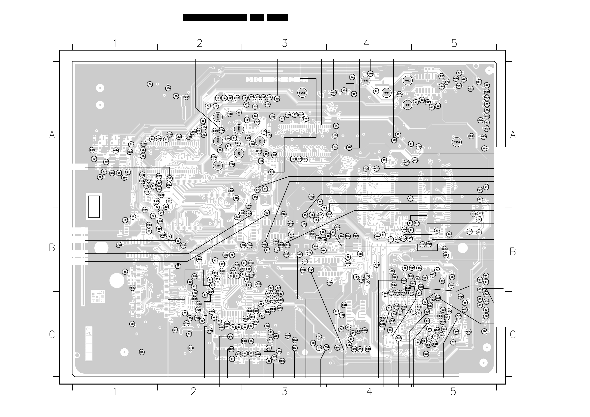
Block Diagrams, Waveforms, Wiring Diagram.
Test points overview Digital Board 1.5
EN 100DVDR70 & DVDR75/0x1 6.
+3V3
+3V3
Resetn_BE
Resetn
+3V3+3V3
+12V +5V
+3V3
Resetn_VE
-5V
+3V3
Sysclk_Empress
EMI_PROCCLK
Sysclk_ProgScan
AE_DATAO
VSYNC
HSYNC
+3V3
+3V3
ACC_ACLK_OSC
Sysclk_VSM_5508
+3V3
VE_DSn
VE_DTACKn
ACC_ACLK_PLL
+3V3
Mute
VIP_ICLK
+3V3
VSOUT
HSOUT
DAC-A/Y
DAC-B
DAC-C
Cr
YCb
+5V
Reset_DVIO
+5V
+3V3
+3V3
+3V3
+3V3
+3V3
+3V3
+3V3
CL 16532145_034.eps
101201
 Loading...