

Page 1
HDD / DVD Recorder Combi
ServiceService
Service
Service
Service
DVDR520H/00/02/05/37
Service Manual
©
Copyright 2004 Philips Consumer Electronics B.V. Eindhoven, The Netherlands
All rights reserved. No part of this publication may be reproduced, stored in a retrieval system or
transmitted, in any form or by any means, electronic, mechanical, photocopying, or otherwise
without the prior permission of Philips.
Published by LO-MF AV System Printed in The Netherlands Subject to modification
Version 1.1
GB
3139 785 30851
Page 2

HDD/DVD Recorder Combi 2
CONTENTS
1. Specification ……. ……………………………..……………………… 1-1
2. Exploded View Drawing…………………………………………….. 2-1
3. Introduction ………………………..……………….………………..… 3-1
4. Product Validation Strategies and Process
4.1 System Block Diagram…………………………………………. 4-1
4.2 Main Board ………………………………………………………. 4-2
4.3 Front Panel ………………………………………………………… 4-2
4.4 Power PCB …………………………………………………………. 4-2
4.5 Power Module …………………………………………………….. 4-2
5. Test Tool Instruction ……………………..……………………………...…5-1
6. Fault Finding Tree………………………………….………………………. 6-1
7. Disassembly Instruction
7.1 Disassemble the Top-Cover. ……………………………………. 7-1
7.2 Disassemble the Drive……………………………………………. 7-2
7.3 Disassemble HDD …………………………….…………………… 7-3
7.4 Disassemble the M/B ………………………….…………………. 7-4
7.5 Disassemble Power module. …………………………………… 7-5
7.6 Jump of HDD & ODD………………………………………………. 7-6
8.
Firmware Update …………………………………………….………… 8-1
9. Spare parts list ….……………………………….………………………… 9-1
Page 3
HDD/DVD Recorder Combi 3
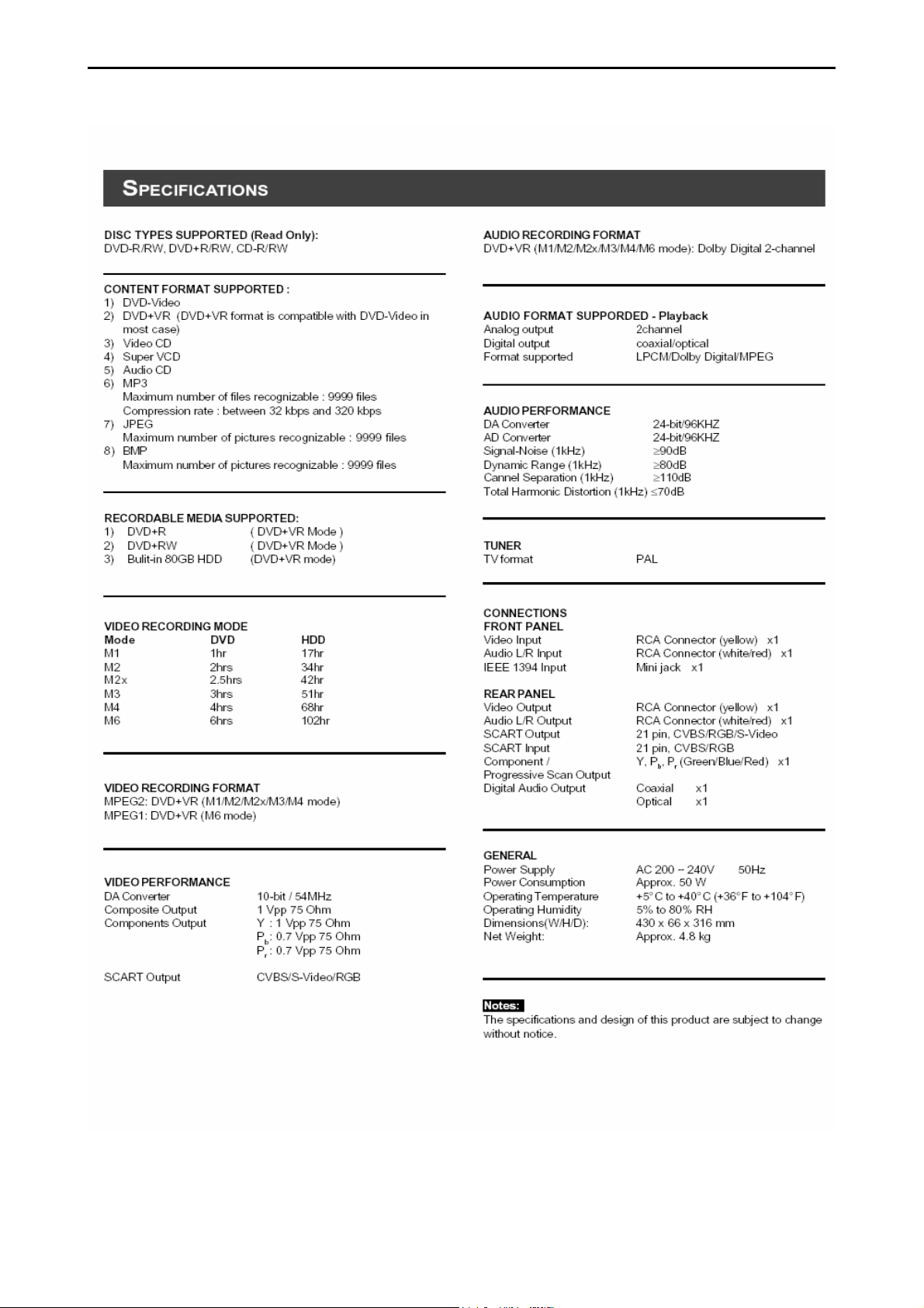
1. Specifications
Page 4

HDD/DVD Recorder Combi 4
2. Exploded View Drawing
Page 5
HDD/DVD Recorder Combi 5
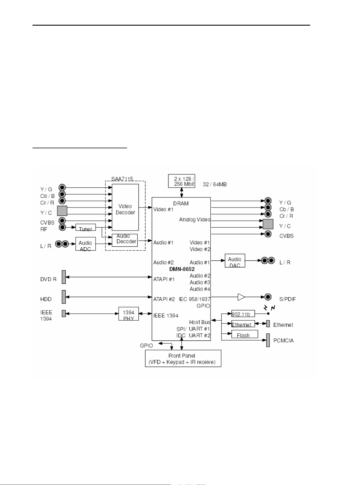
3. Introduction
This document states engineering specifications of both hardware and firmware of
DVDR520H.
DVDR520H adapts LSI DMN8652 chip, DMN-8652 is a single chip dual drive
(HDD/DVD) recorder processor. DMN-8602/DMN-8652 will be the evolutionary
product family after DMN-8600 and DMN-8650. In this sense, DMN-8602/8652 will
offer the same features as their predecessors, allow cost saving at the system level
due to integration, and offer more features at the C-Ware level.
System Requirements
Page 6
HDD/DVD Recorder Combi 6
4. Product Validation Strategies and Process
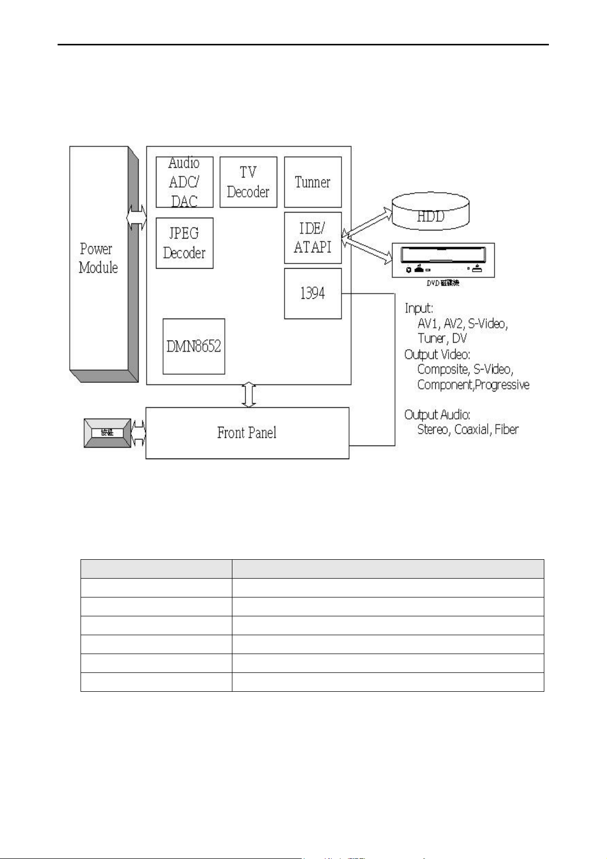
4.1. System Block Diagram
4.1.1 Front Panel
There are six parts in the front panel of DVDR520H: (A) POWER, (B) AV Input 2 (C)
DVD+/-RW Drive, (D) LED Display (E) IEE1394 (F) Command Buttons.
Part Button/Display
(A)POWER (A-1) POWER
(B)AV Input 2 (B-1) VIDEO IN, AUDIO IN (*)
(C)DVD+RW Drive DDW-401s
(D)LED Display (D-1) LED Displayer
(E)IEEE1394 (E-1) IEEE1394 4-pin mini connector
(F)Comment Buttons (F-1) ~ (F-6) are to be defined
¾ AV Input 2: For easy access, standard red (right channel), white (left channel), and yellow
(video) CVBS (RCA) audio/video jacks are located on the front panel of the DVDR520H. To
connect a camcorder or other audio/video source, simply connect the unit’s RCA input
jacks to the corresponding output jacks on the other side.
Page 7

HDD/DVD Recorder Combi 7
4.1.2 Rear Panel
AV Input 1
The rear panel of the DVDR520H features
standard red (right channel), white (left
channel), and yellow (video) CVBS (RCA)
audio/video jacks, such as those are
commonly found in VCRs, record players,
and a wide variety of other audio/video
sources.
other display device.
AV Output for Component Colors:
YCbCr
The rear panel AV Output of the
DVDR520H also features a component
colors (YCbCr) output, which allows a
higher-quality connection to a
camcorder, television, or other display
AV Input 1 for S-VIDEO IN
The rear panel AV Input 1 of the
DVDR520H features an S-Video
connector, which allows a higher-quality
connection to a camcorder, television, or
other video source. When recording
from the S-Video source, the audio input
will be sourced from the red (right
channel) and white (left channel) audio
jacks (labeled “R” and “L”, respectively)
on the rear panel.
AV Output
The rear panel of the DVDR520H features
standard red (right channel), white (left
channel), and yellow (video) CVBS (RCA)
audio/video jacks, such as are commonly
found in VCRs, players, and a wide
variety of other audio/video sources.
device.
2CH Audio Output
The rear panel of the DVDR520H features
a set of 2CH audio connectors, which
allows a high-quality audio output.
Digital Audio Output
The rear panel of the DVDR520H features
a coaxial connector and an optical
connector, which allows a high-quality
audio output.
Tuner
The rear panel of the DVDR520H features
a set of Tuner, which allows recording
broadcast programs with stereo audio at
following areas: NTSC – USA/Taiwan, PAL:
B/G/D/K/I. Besides the cable TV signal
input, a loop-through connector is also
AV Output for S-VIDEO
The rear panel AV Output of the
DVDR520H features an S-Video
connector, which allows a higher-quality
connection to a camcorder, television, or
provided.
Page 8

HDD/DVD Recorder Combi 8
4.2 Main Board
z Main processor and MPEG CODEC : DMN-8652
z RAM : 256MB DDR
z FLASH : 4MB
z TV Encoder : NTSC/PAL Composite, S-Video or Component
z TV Decoder : NTSC/PAL Composite or S-Video
z Audio Input : Stereo
z Audio Output : Stereo
z Tuner : NTSC or PAL, monotone
z IEEE 1394 PHY : IEEE1394a, 100/200/400Mbps
z IDE : 1. Port
z Front panel I/O : 1. IR interface
2. LED display module
3. Scheduled boot-up
4. Repeat key scan (up to 5 times per second)
5. System power on/off control
6. Extended I/O
4.3 Front Panel
z LED display module : 8 numeric characters
z Key : 6
z RCA jack : 1
z Mini IEEE-1394 jack : 1
z IR receiver : 1
4.4 Power PCB
z Key : 1
4.5 Power module
z Input: 100V ~ 240V, 50/60Hz
z Output: 12V / 5V / 3.3V / AUX_5V
z Capacity: ~50W
Page 9
HDD/DVD Recorder Combi 9
5. Test tool introduction
There will be a testing DVD disc (for NTSC system named as 5-1 disc, for PAL system
named as 5-2P disc) as a tool when repair, below will introduce the content of the
disc
5.1 Performance Testing Procedure mainly contains 6 parts:
1). Video Signal Test
2). Speaker & Sound Signal Test
3). Music Demo
4). Video Demo
5). Karaoke Demo
6). Digital Signal Test (not usable for the time being)
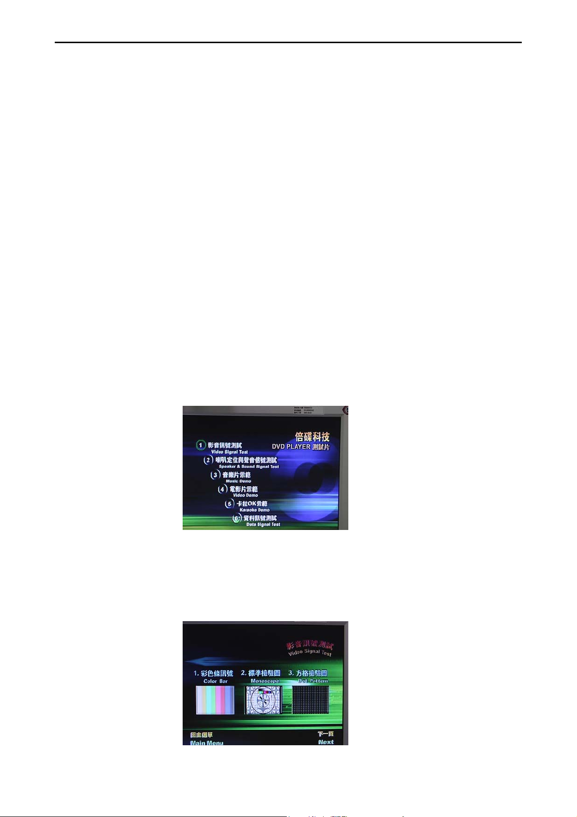
5.2 Test Instructions:
1). Video Signal Test need go through 6 screen pictures to check the
output
Note of Step:
Login the picture as below for no. 1--Video Signal Test
Then, 3 pictures will show up on the screen: 1.Color bar, 2.Mono scope
and 3.Dot Pattern.
And test will automatically go on to playback the 3 pictures shown as
below:
Page 10

HDD/DVD Recorder Combi 10
¾ Test Criteria:
Color bar has sharp, bright and stable color show;
Mono scope or Dot pattern has no tilt or twisted effect;
The RGB picture as below has normally good effect to the naked eyes.
If anything undeterminable, please refer to the following factors to evaluate:
Video Performance (The test appliance is Tektronix VM 700/s-video VM500/Component):
DA Converter 10-bit/54 MHZ
Composite Output 1Vpp &5 Ohm
S-video Output Y: 1Vpp 75Ohm
C: 0.3Vpp 75 Ohm
Component
Output
Y: 1Vpp 75Ohm
Pb: 0.7 Vpp 75 Ohm
Pr: 0.7 Vpp 75 Ohm
2). Speaker & Sound Signal Test is to test its output audio fineness and locating
efficiency of the speaker.
Note of Step:
Select no.2 --- Speaker & Sound Signal Test in the login. The test will check the
locating efficiency and audio signal as well as special frequency.
¾ Test Criteria:
The standard audio output is clear without popping and the signal output from Hi-Fi is normal.
If anything undeterminable, please refer to the following factors to evaluate:
Audio Performance (The test appliance is Audio position SWR-2122U)
Page 11

HDD/DVD Recorder Combi 11
DA converter 24 –bit /192KHZ
AD converter 24≦ -bit
Signal-Noise (1kHZ) 90dB≧
Dynamic range(1kHZ) 80dB≧
Cannel Separation(1kHZ) 80dB≧
Total Harmonic Distortion(1kHZ) ≦-65dB
3). Music Demo test is to check the video output signal good without noise.
4). Video Demo test is to check the normal function of subtitle, language, angle
and so on.
Login in the main test menu for no.4 Video Demo and press the key of “Navi” on
remote to choose “Subtitle” “Audio” and “Angle” to check the normal function.
Navi button
Page 12

HDD/DVD Recorder Combi 12
5). Karaoke Demo Test:
5.3 Items of the DVD disc in common use when rma
5.3.1 Necessary Repairing tools in need to test the following 3 items:
A. Video output
B. Audio output
C. AV output (film)
5.3.2 Note of step:
STEP1:
A. Insert the DVD VIDEO 5-1 / 5-2P disc and it will auto playback
B.Press the key of “Top Menu” on remote to login the menu
C.Select the item 1—Video Signal Test and press “Enter” to start the test on any
color difference in Color bar and the standard fineness of the RGB, then press
Page 13

HDD/DVD Recorder Combi 13
“Top Menu” back to test menu
STEP2:
A.Select item 2—Speaker & Sound Signal Test and press “Enter” for the item
1--Speaker & Sound Signal Test, then press “Enter” for “2.0CH” and the “1KHZ
Audio Test”, to test the R/L- C’s output is normally good or not. And then press
“Top Menu” back to menu
B.In the menu to choose item 4--Video Demo and press “Enter” to start the test, to
check the normally good video and audio output , then press “Top Menu” back
to test menu.
STEP3:
Take out the test disc and the test is over.
Page 14

HDD/DVD Recorder Combi 14
6. Fault Finding Tree
Before repair please make good connection with all input and output device
Replace front
display board
Replace
drive
Front panel display?
Y
N
Display
Normal?
Y
Press
“EJECT”buttom to
N
verify if the player
boot up and also
tray come out ?
Y
N
Power
cord plug?
Open top cover
and use
“multimeter” to
verify if the
power module
output both
5V&12V
Replace front
display board
Y
Y
N
Plug the
power cord
N
Replace
power module
Replace
M/B
Replace
HDD
Put a movie
N
disc and press
the “play” to
verify if AV
output corret?
N
Use the “Erase”
function of the
“disc tool “ to
verify if the HDD
work normal?
Y
Y
NPF
Page 15

HDD/DVD Recorder Combi 15
Recording
Select Source view
and display OK
N
Select AV sources
but no
video/audio
N
AV Sources video is
black&white or
shift
N
Select Target to
Y
Y
Y
HDD/DVD OK
Check connection
Check if TV system
of input
device is
different
Press Record button
to start
recording
N
Show “Protected
Content”
N
Show “Wrong
Signal Type”
N
Source DVD is not
Y
Y
allowed to
reproduce
Recording disc was
formatted
when use
different TV
setting
Select DV but no
video
Gray screen-check
Y
connection
Black screen-check
TV system of the
DV or DV tape
Show “Write Fail” Bad write quality on
Y
this disc
Page 16

HDD/DVD Recorder Combi 16
DVD Playback
Select Target DVD,
eject
Load supported
Y
disc DVD+R/RW, CD-R
N
Invalid disc or
Data disc
N
Blank disc
Y
Y
Y
Auto-play DVD
VCD SVCD
and Media
Disc
Not supported
format
Show “Preparing”
then start preformat for
recording
Page 17

HDD/DVD Recorder Combi 17
Reference of defect symptoms for repair
• After power cord plug in ,LED no display , but AV output normal after power
on -> replace display board
• After power on , the color of the screen isn’t correct -> replace M/B
• After power on , the fan doesn’t work -> replace power module / Fan
• Can’t eject or show “No Disc” -> replace drive
• Can’t auto format any brand new disc -> replace drive
• Recording will auto stop or hang -> replace M/B & drive
• Playback will have mosaic -> replace M/B
• Can’t format HDD -> replace HDD
• Can’t record with HDD -> replace HDD
• No Audio or audio output abnormal -> replace M/B
• Optical / Coaxial no output when the setting is set as DTS output -> replace
M/B
• Can’t update F/W through drive -> replace drive
• Can’t detect DV when plug in/out with a DV -> replace display board
• AV1 input mode doesn’t output video / audio when connected to a normal
external AV source -> replace display board
• AV2 ( Scart) / S-Video input mode doesn’t output video / audio when
connected to a normal external AV source -> replace M/B
Page 18

HDD/DVD Recorder Combi 18
Module Fail / Problem Remedy / Symptom
Run Disc Tool/Format/HDD show "Fail", this could be a bad HDD
HDD
DVD Drive
DVD/CD disc
Run Disc Tool/Defragment show "Fail", this could be a bad HDD
Format no problem but show "Write Fail" during recording , this could be a
bad HDD
Load any disc always show "No disc", this could be a bad DVD drive
Load some kind of discs always show "No disc". For example load DVD no
problem, but load CD-R show "No disc", this could be a bad DVD drive
Cannot open tray. User can try to power off the recorder, and then press
"Eject" to boot again. If still can not open, this could be a bad DVD drive.
If tray open successfully and there is a disc inside, it's the disc cause drive
busy. Try another disc, if user can tray in/out no problem, the drive should
be ok.
Run Disc Tool/Format/DVD show "Fail". This could be a bad disc or not
compatible with our DVD drive.
Format no problem but show "Write Fail" then stop during recording. Press
"Record" again may be user can continue record, but part of the
audio/video on this disc may not smooth. This could be a bad disc or not
compatible with our DVD drive.
Take long time to load disc then show “Invalid Disc". The disc could be a
bad disc or unsupported format
Connect power cord, but LED display show nothing, Press remote or
button on the panel still nothing happened. This could be a power board
Power
Remote
Front Panel
problem
Replace power cord if find any available. We use a common power cord
user may able to find the same one on his other electronic products
Press buttons on remote but nothing happened, system can still power on
by buttons on panel. OSD doesn't show system receive any key. This
could be a bad remote or ran out of battery.
Or it could be a bad receiver on the front panel
System can power on and work by remote no problem, but press buttons
on panel does not work. This could be a bad front panel
Page 19

HDD/DVD Recorder Combi 19
Module Fail / Problem Remedy / Symptom
Can not see any display or color abnormal, video distortion. Make sure
Video Output
Audio Output
TV Tuner
cables connected correctly. Try another output like S-video, AV,
Component, and Scart.
Run SETUP to select available video output
Can not hear any sound output through speakers of TV or amplifier.
Make sure cables connected correctly. Try another output like AV,
optical, coaxial
Playing DVD movie, when select DTS out on DVD audio menu no audio
output. User needs to run SETUP/Audio/DTS to set DTS ON
Run SETUP, Tuner setting correctly, but after scan TV channel can not
select correct TV programs. Run SETUP/ Tuner/TV signal, select Antenna
or Cable then run "Channel Scan" again, don't use "Auto". "Auto" will
re-arrange channel table and remove channel numbers not available.
User selects TV signal/country correctly, after scan still cannot select
channel, this could be a bad TV tuner.
Connect external source like AV, S-video, Scart, DV-link (1394) can not
see the video input. Make sure cables connected correctly. If these
External source
Can not Real-time Record
signals connect to other AV products no problem. This could be a bad
connector
For DV, user need to know the DV is NTSC/PAL, and the playing DV
tape is NTSC/PAL. They must be the same TV type as the recorder to
make it works properly.
Show "Protected Content", it's Copy-Protected and not allowed to
copy
Show "Wrong Signal Type" when record to disc. The disc was formatted
by different TV system (NTSC/PAL). For DVD±RW, user can reformat this
disc (contents on this disc will be erased). For DVD±R, user can only
change another disc
Press "Record" shows key blocked, will not start recording. Maybe user
select wrong Target device. Press Target to choose HDD/DVD
Empty DVD-R/RW, CD-R/RW user needs to format by Disc Tool before
recording
Open "Timer" record again, there is a message shows why it failed,
Can not Timer Record
please move the cursor to column status and it will show the reason it
fails
Selected recording "Target" is unable to record when Timer starting
time
Page 20

HDD/DVD Recorder Combi 20
Module Fail / Problem Remedy / Symptom
Cannot play a disc
Copying
System Upgrade
If it's not "Invalid disc", could be unsupported format/contents in the disc
Show "Fail" when copying files/discs, it could be unsupported format
Show "Fail" when copying recorded DVD+VR title, it could be out of disc
space
Follow the firmware update procedure in the chapter”Firmware update”.
If upgrade failed (power failure during upgrade or …), maybe every time
system power on will show "Put Cd In". Users most load the upgrade disc
again to recover.
Page 21

HDD/DVD Recorder Combi 21
7. Disassembly introduction
7.1 Disassemble the TOP-COVER:
Step 1:
Loosening the fixed screws of the TOP-COVER totally 6 screws, 4 on the rear panel
and 1 on the left side and the other on the right side of the TOP-COVER, (as PICTURE
1 & 2 & 3)
(PICTURE 1) (PICTURE 2)
(PICTURE 3)
Step 2:
Pull back to remove the TOP-COVER and let the cover-top lie on horizontally
smooth desk to prevent being out-of-shape place upside down (as
PICTURE 4)
(PICTURE 4)
Page 22

HDD/DVD Recorder Combi 22
7.2 Disassemble the Drive:
Power cord
IDE cable
(PICTURE 5) (PICTURE 6)
4
SCREWS SCREWS
1
3
(PICTURE 7 ) (PICTURE 8)
Step 1: Tray out Æ pull out the door and lift up to disassemble the tray door (as
PICTURE 6)
Step 2: Tray in Æ Power off Æ unplug the power cord
Step 3: Disassembly the top cover
Step 4: Unplug the power cord and IDE cable (as PICTURE 5)
Step 5: Remove the four fixed screws of the drive (screw 1~4 as PICTURE 7 &8)
2
Step 6: Remove the Drive
Page 23

HDD/DVD Recorder Combi 23
7.3 Disassemble HDD:
Power cord
IDE cable
SCREWS
(PICTURE 9)
2
(PICTURE 10) (PICTURE 11)
(PICTURE 12)
Step 1: Disassembly the top cover
Step 2: Unplug the power cord and IDE cable (as PICTURE 9)
Step 3: Loosen the screws off the chassis (1~4 in PICTURE 10 & 11)
Step 4: Take out the HDD (as PICTURE 12)
Page 24

HDD/DVD Recorder Combi 24
7.4 Disassemble the M/B:
IDE cable
(PICTURE 13) (PICTURE 14) (PICTURE 15)
Power cord
2
SCREWS
(PICTURE 16 ) (PICTURE 17)
(PICTURE 18) (PICTURE 19)
Step 1: Unplug the power cord and IDE cable of the HDD module (as PICTURE 13)
Step 2: Remove the HDD module from the M/B first, unfix the 4 screws of the HDD
module (as PICTURE14, 15, 16)
SCREWS
Step 3: Unfixed the screw of the M/B and remove all the cable (7 cables)
connected to M/B (as PICTURE 17 & 19)
Step 4: Loosen the 5 screws off the rear panel (as PICTURE 18)
Note: Tuner can be removed and reused if isn’t broken when M/B is disassembled
Page 25

HDD/DVD Recorder Combi 25
7.5 Disassemble the Power Module
(PICTURE 20)
Step 1: Disconnect all the cables connected to other module (total 4 cables as
red circle in PICTURE 20)
Step 2: Loosen the screws off the chassis (1~5 in PICTURE 20)
Step 3: Take out the power module
Page 26

HDD/DVD Recorder Combi 26
7.6 JUMP of HDD & ODD
HDD
ODD
JUMP
JUMP
Page 27

HDD/DVD Recorder Combi 27
8. Firmware Update
1. Burn the firmware on a single-session ISO disc.
2.
Power on the system.
3.
After system is ready, load the firmware update disc.
4.
System will start detect the firmware image and if the image is detected,
LED will show "F-UP xxxx", where "xxxx" is the build number.
5.
If system detects the image file, a confirm dialog will display on the screen.
Page 28

HDD/DVD Recorder Combi 28
Follow the instruction to complete the update process.
6.
If system firmware is updated without error, LED will show "done". Else
"error" will show.
Reboot the system.
7.
Page 29

HDD/DVD Recorder Combi 29
SERVICE TOOLS
9965 000 26088 Test Disc 5-2P for PAL system
9965 000 26216 Test Disc 5-1 for NTSC system
SERVICE SPARE PARTS
2 9965 000 26091 DVDR MECHANISM MODULE
5+6+7 9965 000 26092 FRONT PANEL + PCBA ASSEMBLY
10 9965 000 26093 MAIN BOARD WITHOUT TUNER
11 9965 000 26094 FAN
14 9965 000 26095 HD DRIVE HDD_80G_5400
15 9965 000 26096 POWER BOARD
16 9965 000 26090 TUNER UNIT PAL
16 9965 000 26220 TUNER UNIT NTSC
9965 000 26089 REMOTE CONTROL UNIT
Note: Only the parts mentioned in this list are normal service spare
parts.
/00/02/05
/37
/00/02/05
/37
Page 30

HDD/DVD Recorder Combi 29
REVISION LIST
Version 1.0
* Original Release
Version 1.1
* Correction of page 21 - Missing diassembly instruction 7.1
 Loading...