

Page 1
HDD & DVD Recorder
CLASS 1
LASER PRODUCT
DVDR3570H/75/97
DVDR3590H//75/97/93
Contents Page
1 Technical Specifications and Connection
Facilities 2
2 Safety Information, General Notes & Lead
Free Requirements 5
3 Directions for Use 7
4 Mechanical Instructions 10
5 Firmware Upgrading, Diagnostic Software,
Alignment and Test Procedures 14
6 Block Diagrams,Waveforms, Wiring Diagram 95
Overall block diagram 95
Wiring diagram 96
Waveforms of Analog Board 97
Waveforms of Digital Board 98
Waveforms of HDMI Board 99
Test Points Overview for HDMI Board 100
Test Points Overview for Analog Board 101
Test Points Overview for Digital Board 102
©
Copyright 2007 Philips Consumer Electronics B.V. Eindhoven, The Netherlands.
All rights reserved. No part of this publication may be reproduced, stored in a
retrieval system or transmitted, in any form or by any means, electronic,
mechanical, photocopying, or otherwise without the prior permission of Philips.
Contents Page
7 Circuit Diagrams and PWB Layout 103
Analog Circuit Diagrams 103
Analog Layout Diagrams 106
Front Circuit Diagrams 108
Front Display/Connector Layout Diagrams 110
Front Standby Circuit & Layout Diagrams 111
LecoPlus INIT Circuit & Layout Diagrams 112
Digital Circuit Diagrams 113
Digital Layout Diagrams 121
HDMI Circuit Diagrams 123
HDMI Layout Diagrams 127
8 IC Internal Block Diagrams 129
Analog Board 129
Digital Board 131
HDMI Board 140
9 Exploded view & Service parts list 158
Exploded View of the set 158
Service parts list 159
10 Revision list 160
Published by KC-TE 0718 V&MA Printed in the Netherlands Subject to modification EN 3139 785 32804
Version 1.4
Page 2
EN 2 3139 785 328041. Technical Specifications and Connection Facilities
1. Technical Specifications and Connection Facilities
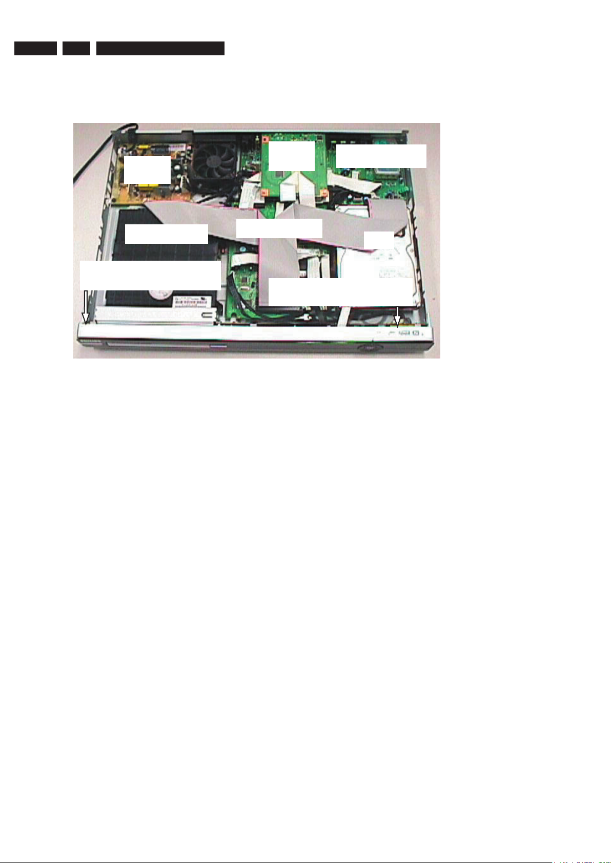
1.1 PCB Locations
PSU
Board
Basic Engine
Standby Board (Behind
the Front Cabinet)
1.2 General:
Power supply : 220-240V, ~50 Hz
Power consumption
DVDR3570H : 28 W
DVDR3590H : 35 W
Standby power consumption : < 3.7 W
1.3 RF Tuner (Analogue)
Test equipment: Fluke 54200 TV Signal generator
Test streams: Philips Standard test pattern
1.3.1 System
B/G, I, L/L’, D/K
1.3.2 RF - Loop Through:
Frequency range : 43 MHz – 860 MHz
Gain (ANT IN – ANT OUT)
without amplifier : -4dB ± 2dB
Gain (ANT IN – ANT OUT)
with amplifier : From 2dB + 3dB until
2dB – 2dB
1.3.3 Receiver:
Output of Cinch connector to be used for measurements
(direct output from front end)
Video Performance:
Frequency Response : 0 ± 4dB (0 to 4.4 MHz)
Group Delay : 0 ± 150 n sec
(0 to 4.4 MHz)
HDMI
Board
Analog Board
Digital Board
Front Board (Behind the
Front Cabinet)
Audio Performance:
Audio analogue Mono :
Frequency Response relative to
1 kHz :
S/N unweighted : ≥ 40dB (Quasi peak,
S/N weighted : ≥ 45dB (Quasi peak,
Harmonic distortion at 1 kHz : ≤ 1.5% (FM: ± 25 kHz)
Harmonic distortion at 1 kHz : ≤ 2 %
Audio NICAM Stereo/Dual :
Frequency Response relative to
1 kHz : 0 ± 3dB
S/N unweighted : ≥ 65dB (Quasi peak,
S/N weighted : ≥ 70dB (Quasi peak,
Harmonic distortion at 1 kHz : ≤ 0.5% (Headroom:
Channel Separation : ≥ 45dB
1.3.4 Tuning
Tuning Frequency Range : 45.25 MHz – 857 MHz
Antenna Level for 40dB luminance
S/N (video unweighted) at 75Ω : ≤ 40dBμV (High End)
Automatic Search Tuning:
Scanning time auto search without
RF Signal : < 2.5 min.
Stop level (vision carrier) : ≥ 40dBμV
Maximum tuning error during
operation (drift) : ± 100 kHz
Maximum tuning error of a recalled
program : ± 62.5 kHz
HDD
0 ± 3dB
(100 Hz to 12 kHz)
22 Hz – 22 kHz)
CCIR 468)
(AM: m = 54% L/L’)
(40 Hz to 15 kHz)
22 Hz – 22 kHz)
CCIR 468)
System I – 21.1dB,
all others – 16.5dB)
≤ 60dBμV (Low End)
(Typical 3 minutes)
Page 3

EN 33139 785 32804 1.Technical Specifications and Connection Facilities
Tuning Principles:
Automatic system recognition
Manual Selection in “Store” mode
Storage of frequencies at each random
position number
1.4 Analog Inputs / Outputs
1.4.1 Audio/Video Front Input Connectors
(CAM 1) AUDIO – Cinch (L/R):
Input voltage : 2.2Vrms max
Input impedance : > 10kΩ
(CAM1) VIDEO – Cinch:
Input voltage : 1Vpp ± 3dB
Input impedance : 75Ω
1.4.2 Audio/Video Rear Input Connectors
AUDIO IN (AUDIO 1/2) – Cinch (L/R):
Input voltage : 2.2Vrms max
Input impedance : > 10kΩ
CVBS IN (VIDEO IN) – Cinch:
Input voltage : 1Vpp ± 3dB
Input impedance : 75Ω
S-VIDEO IN (VIDEO IN) – Hosiden:
According to IEC 933-5
Superimposed DC-level on pin 4 (load > 100kΩ)
< 2.4V is detected as 4:3 aspect ratio
> 3.5V is detected as 16:9 aspect ratio
Input voltage Y : 1Vpp ± 3dB
Input impedance Y : 75Ω
Input voltage C : 300mVpp ± 3dB
Input impedance C : 75Ω
COMPONENT VIDEO IN – Cinch (Y/Pb/Pr):
According to EIO-770-I-A, EIA-770-2
1.4.3 Audio/Video Output Connectors
(AUDIO OUT) AUDIO – Cinch (L/R):
Output voltage : 2Vrms max
Output impedance : > 10kΩ
(VIDEO OUT) CVBS OUT– Cinch:
Output voltage : 1Vpp ± 3dB
Output impedance : 75Ω
(VIDEO OUT) S-VIDEO OUT - Hosiden:
According to IEC 933-5
Superimposed DC-level on pin 4 (load > 100kΩ)
< 2.4V is detected as 4:3 aspect ratio
> 3.5V is detected as 16:9 aspect ratio
Output voltage Y : 1Vpp ± 3dB
Output impedance Y : 75Ω
Output voltage C : 300mVpp ± 3dB
Output impedance C : 75Ω
COMPONENT VIDEO OUT – Cinch (Y/Pb/Pr):
According to EIA-770-1-A, EIA-770-2-A
1.5 Digital Inputs / Outputs
1.5.1 CAM 2 DV IN (IEEE 1394 Digital Video Input)
Implementation Standard according:
IEEE Std 1394-1995
IEC61883 - Part1
IEC61883 - Part 2 SD-DVCR (02-01-1997)
Specification of consumer use digital VCR’s using 6.3mm
magnetic tape – dec.1994
Mechanical connection according to Annex of IEC 61883-1
1.5.2
(AUDIO OUT) COAXIAL DIGITAL OUT – Cinch
LPCM : according IEC 60958
MPEG 1, MPEG 2, AC3 : according IEC 61937
DTS : according IEC 61937 +
1.5.3 USB
Compatibility : USB 2.0
Type of connector : Series A Connector
1.5.4 HDMI Output
Compatibility : HDMI version 1.1
Type of connector : Type A connector
addendum
(19 pins)
1.6 Video Performance
1.6.1 SNR
PAL
RGB CVBS Y/C
≥ 55 dB Lumincance: ≥ 55 dB
NTSC
Y Pb Pr CVBS Y/C
≥ 55 dB Lumincance: ≥ 55 dB
1.6.2 Bandwidth
PAL
RGB CVBS Y/C
0.5 to 4 MHz:+1dB/
-2dB
4.8 MHz:-3dB 4.8 MHz:-3dB C:700 kHz
5.8 MHz:-6dB 5.8 MHz:-6dB
NTSC
YPbPr CVBS Y/C
4.2 MHz:-3dB 4.2 MHz:-3dB Y:
5.8 MHz:-6dB 5.8 MHz:-6dB C:≥ 700 kHz
With Pscan:
8.4MHz -3dB
Chroma: ≥ 55 dB (AM)
≥ 52 dB (PM)
Chroma: ≥ 54 dB (AM)
≥ 54 dB (PM)
0.5 to 4 MHz:+1dB/
-2dB
Y: ≥ 57 dB
C: ≥ 57 dB (AM)
≥ 54 dB (PM)
Y: ≥ 55 dB
C: ≥ 54 dB (AM)
≥ 54 dB (PM)
Y:
4.8MHz-3dB
4.2MHz-3dB
Page 4
EN 4 3139 785 328041. Technical Specifications and Connection Facilities
1.7 Audio Performance CDDA (PCM)
1.7.1 Cinch Output Rear
Output voltage : 1.8Vrms ± 2dB
Channel unbalance : < 0.22dB
Crosstalk 1kHz : > 110 dB
Crosstalk 16Hz – 20kHz : > 110 dB
Signal to noise ratio (unweighted)
20Hz – 20kHz bandwidth limited :
Signal to noise ratio (A-weighted)
RMS 20Hz – 20kHz
bandwidth limited : > 112dBA (mute)
Dynamic range 1kHz : > 90dB
Distortion and noise 1kHz : > 85dB
Distortion and noise 16Hz – 20kHz : > 78dB
Mute (spin-up, pause, access) : > 78dB
> 95dB (mute)
1.8 Dimension and Weight
Set Dimension W x H x D : 435 x 43 x 324 mm
Net Weight : 3.8 kg
1.9 Laser Output Power & Wavelength
1.9.1 DVD
Output power during reading : 1.0mW
Output power during writing : 69mW
Wavelength : 658nm (at 25 °C)
1.11 Supported Disc Types and Media Speed for
Recording
Disc Media Speeds
DVD+R 1x - 16x
DVD+RW 2.4x - 8x
DVD-R 1x - 16x
DVD-RW 2.4x - 4x
DVD+R DL 2.4x
1.12 Diversity Matrix
DVDR3570H DVDR3590H
Hard Disk capacity 160 GB 250 GB
1.9.2 CD
Output power : 1.2mW
Wavelength : 783nm (at 25 °C)
1.10 Playability
Video Playback
1. Playback Media:
CD-R/CD-RW
DVD-R/-RW, DVD-Video, Video
CD/SVCD, DVD+R DL, DVD-R
DL, USB flash drive
2. Compression Formats:
MPEG2, MPEG1, DivX 3.11, DivX
4.x, DivX 5.x, DivX 6.0, MPEG4
Audio Playback
Playback Media:
1.
Audio CD, CD-R/R
DVD+R/+RW, DVD-R/-RW, MP3CD, MP3-DVD, USB flash drive,
WMA-CD
2. Compression Format:
Dolby Digital, MP3, MPEG2
Multichannel, PCM, WMA
3. MPEG1 bit rates: 64-384 kbps
and VBR
Still Picture Playback
1. Playback Media: CD-R/RW
DVD+R DL, DVD+R/+RW, DVDR/-RW, Picture CD, USB Digital
Camera (PTP), USB flash drive
2. Picture Compression Format:
JPEG, JPEG digital camera
photos
3. Picture enhancement: Slideshow
with MP3 playback, Create
albums, Rotate, Slideshow with
music playback, Zoom
, DVD+R/+RW,
, DVD+R DL,
W
,
x
x
x
x
x
x
x
x
Page 5
CLASS 1
LASER PRODUCT
2. Safety Information, General Notes & Lead Free Requirements
EN 53139 785 32804 2.Safety Information, General Notes & Lead Free Requirements
2.1 Safety Instructions
2.1.1 General Safety
Safety regulations require that during a repair:
• Connect the unit to the mains via an isolation transformer.
• Replace safety components, indicated by the symbol
only by components identical to the original ones. Any
other component substitution (other than original type)
may increase risk of fire or electrical shock hazard.
Safety regulations require that after a repair, you must return
the unit in its original condition. Pay, in particular, attention to
the following points:
• Route the wires/cables correctly, and fix them with the
mounted cable clamps.
• Check the insulation of the mains lead for external
damage.
• Check the electrical DC resistance between the mains
plug and the secondary side:
1. Unplug the mains cord, and connect a wire between
the two pins of the mains plug.
2. Set the mains switch to the ‘on’ position (keep the
mains cord unplugged!).
3. Measure the resistance value between the mains
plug and the front panel, controls, and chassis
bottom.
4. Repair or correct unit when the resistance
measurement is less than 1 MΩ.
5. Verify this, before you return the unit to the customer/
user (ref. UL-standard no. 1492).
6. Switch the unit ‘off’, and remove the wire between the
two pins of the mains plug.
2.1.2 Laser Safety
This unit employs a laser. Only qualified service personnel
may remove the cover, or attempt to service this device (due
to possible eye injury).
2.2 Warnings
2.2.1 General
,
2.2.2 Laser
• All ICs and many other semiconductors are susceptible to
electrostatic discharges (ESD,
). Careless handling
during repair can reduce life drastically. Make sure that,
during repair, you are at the same potential as the mass
of the set by a wristband with resistance. Keep
components and tools at this same potential.
Available ESD protection equipment:
– Complete kit ESD3 (small tablemat, wristband,
connection box, extension cable and earth cable)
4822 310 10671.
– Wristband tester 4822 344 13999.
• Be careful during measurements in the live voltage
section. The primary side of the power supply, including
the heatsink, carries live mains voltage when you
connect the player to the mains (even when the
player is ‘off’!). It is possible to touch copper tracks and/
or components in this unshielded primary area, when
you service the player. Service personnel must take
precautions to prevent touching this area or components
in this area. A ‘lightning stroke’ and a stripe-marked
printing on the printed wiring board, indicate the primary
side of the power supply.
• Never replace modules, or components, while the unit is
‘on’.
• The use of optical instruments with this product, will
increase eye hazard.
• Only qualified service personnel may remove the cover or
attempt to service this device, due to possible eye injury.
• Repair handling should take place as much as possible
with a disc loaded inside the player.
• Text below is placed inside the unit, on the laser cover
shield:
Laser Device Unit
Type : Semiconductor laser
GaAlAs
Wavelength : 650 nm (DVD)
: 780 nm (VCD/CD)
Output Power : 20 mW
(DVD+RW writing)
: 0.8 mW
(DVD reading)
: 0.3 mW
(VCD/CD reading)
Beam divergence : 60 degree
Figure 2-1
Note: Use of controls or adjustments or performance of
procedure other than those specified herein, may result in
hazardous radiation exposure. Avoid direct exposure to beam.
CAUTION VISIBLE AND INVISIBLE LASER RADIATION WHEN OPEN AVOID EXPOSURE TO BEAM
ADVARSEL SYNLIG OG USYNLIG LASERSTRÅLING VED ÅBNING UNDGÅ UDSÆTTELSE FOR STRÅLING
ADVARSEL
SYNLIG OG USYNLIG LASERSTRÅLING NÅR DEKSEL ÅPNES UNNGÅ EKSPONERING FOR STRÅLEN
VARNING SYNLIG OCH OSYNLIG LASERSTRÅLNING NÄR DENNA DEL ÄR ÖPPNAD BETRAKTA EJ STRÅLEN
VARO! AVATTAESSA OLET ALTTIINA NÄKYVÄLLE JA NÄKYMÄTTÖMÄLLE LASER SÄTEILYLLE. ÄLÄ KATSO SÄTEESEEN
VORSICHT SICHTBARE UND UNSICHTBARE LASERSTRAHLUNG WENN ABDECKUNG GEÖFFNET NICHT DEM STRAHL AUSSETSEN
DANGER VISIBLE AND INVISIBLE LASER RADIATION WHEN OPEN AVOID DIRECT EXPOSURE TO BEAM
ATTENTION RAYONNEMENT LASER VISIBLE ET INVISIBLE EN CAS D’OUVERTURE EXPOSITION DANGEREUSE AU FAISCEAU
Figure 2-2
Page 6
EN 6 2.
2.3 Lead Free Requirement
Information about Lead-free produced sets
Philips CE is starting production of lead-free sets from
1.1.2005 onwards.
INDENTIFICATION:
Regardless of special logo (not always indicated)
One must treat all sets from 1 Jan 2005 onwards, according
next rules.
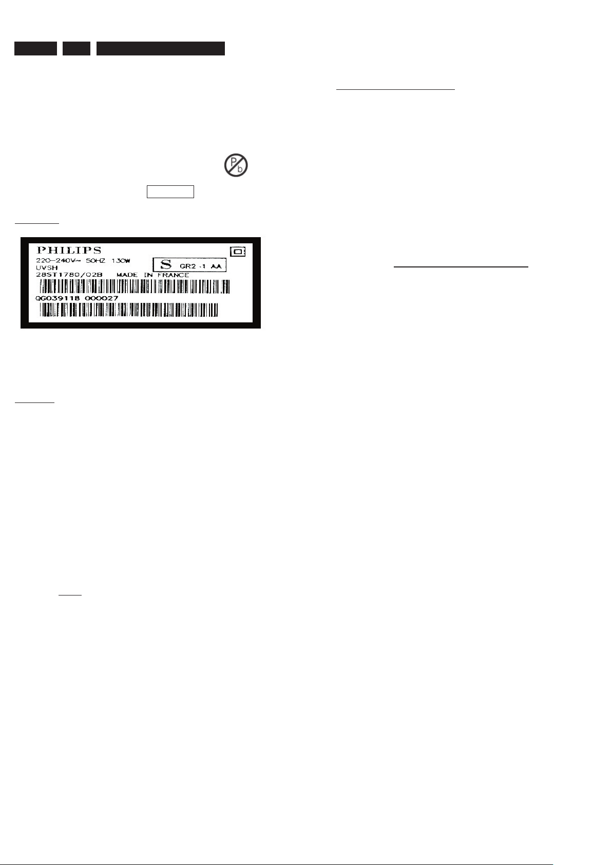
Example S/N:
Bottom line of typeplate gives a 14-digit S/N. Digit 5&6 is the year, digit 7&8 is
the week number, so in this case 1991 wk 18
So from 0501 onwards = from 1 Jan 2005 onwards
to be purchased at external companies.
• Special information for BGA-ICs:
- always use the 12nc-recognizable soldering temperature
profile of the specific BGA (for de-soldering always use
the lead-free temperature profile, in case of doubt)
- lead free BGA-ICs will be delivered in so-called ‘drypackaging’ (sealed pack including a silica gel pack) to
protect the IC against moisture. After opening, dependent
of MSL-level seen on indicator-label in the bag, the
BGA-IC possibly still has to be baked dry. (MSL=Moisture
Sensitivity Level). This will be communicated via AYSwebsite.
Do not re-use BGAs at all.
• For sets produced before 1.1.2005 (except products of
2004), containing leaded solder-alloy and components,
all needed spare-parts will be available till the end of the
service-period. For repair of such sets nothing changes.
• On our website www.atyourservice.ce.Philips.com
you find more information to:
BGA-de-/soldering (+ baking instructions)
Heating-profiles of BGAs and other ICs used in Philips-
sets
You will find this and more technical information within
the “magazine”, chapter “workshop news”.
For additional questions please contact your local repair-helpdesk.
Important note: In fact also products of year 2004 must be treated in this way as long as you
avoid mixing solder-alloys (leaded/ lead-free). So best to always use SAC305 and the higher
temperatures belong to this.
Due to lead-free technology some rules have to be respected by the
workshop during a repair:
• Use only lead-free solder alloy Philips SAC305 with
order code 0622 149 00106. If lead-free solder-pate
is required, please contact the manufacturer of your
solder-equipment. In general use of solder-paste within
workshops should be avoided because paste is not easy
to store and to handle.
• Use only adequate solder tools applicable for lead-free
solder alloy. The solder tool must be able
o To reach at least a solder-temperature of 400°C,
o To stabilize the adjusted temperature at the solder-
tip
o To exchange solder-tips for different applications.
• Adjust your solder tool so that a temperature around
360°C – 380°C is reached and stabilized at the solder
joint. Heating-time of the solder-joint should not exceed
~ 4 sec. Avoid temperatures above 400°C otherwise
wear-out of tips will rise drastically and flux-fluid will be
destroyed. To avoid wear-out of tips switch off un-used
equipment, or reduce heat.
• Mix of lead-free solder alloy / parts with leaded solder
alloy / parts is possible but PHILIPS recommends strongly
to avoid mixed solder alloy types (leaded and lead-free).
If one cannot avoid or does not know whether product is
lead-free, clean carefully the solder-joint from old solder
alloy and re-solder with new solder alloy (SAC305).
• Use only original spare-parts listed in the ServiceManuals. Not listed standard-material (commodities) has
Page 7
Hard Disk / DVD Recorder
DVDR3570H
DVDR3590H
Quick Start Guide
Connect
Set up
Enjoy
1
2
3
What’s in the box?
Hard Disk/ DVD Recorder
RF antenna cable
(connect between
recorder and TV)
Remote Control
and 2 batteries
User
Manual
Audio/Video
cables
SUBTITLE
INFO SELECT EDIT SCART
AUDIO
PAUSE LIVE TV
1
Connect
ANTENNA-IN
TV-OUT
HDMI
OUT
MAINS
COAXIAL
DIGITAL OUT
CVBS OUT
S-VIDEO OUT
VIDEO OUT AUDIO OUT
AUDIO
COMPONENT
VIDEO OUT
P
B
P
R
Y
R
L
CVBS IN
S-VIDEO IN
AUDIO 2AUDIO 1
R
L
P
B
P
R
Y
COMPONENT VIDEO IN
EXT 1
R
L
EXT 2
R
COAXIAL
DIGITAL OUT
CVBS OUT
S-VIDEO OUT
VIDEO OUT AUDIO OUT
AUDIO
COMPONENT
VIDEO OUT
P
B
P
R
Y
R
L
D
C
E
B
A
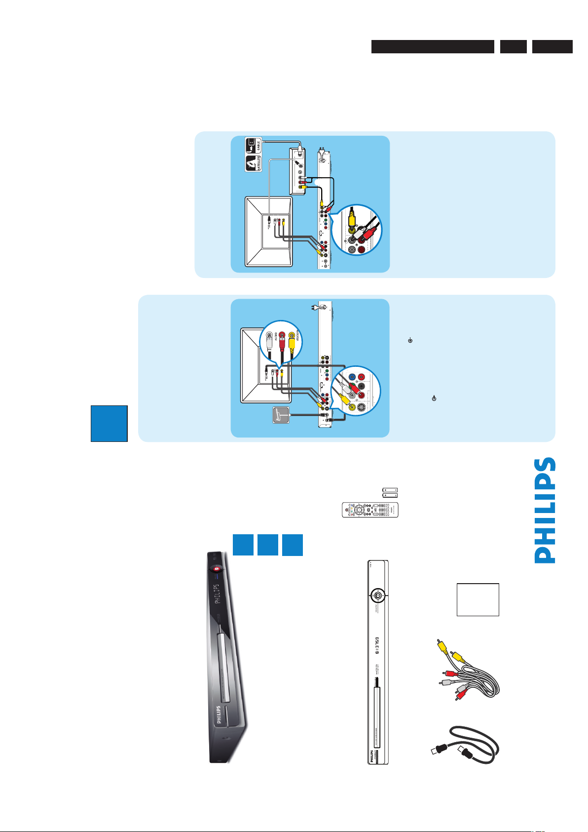
Before connecting
Select the most suitable connection (A or B) based on
the type of device you have and your home set up.
You can also refer to the accompanying User Manual for
other possible connections.
A
Connecting Recorder and TV
with antenna only
A Unplug the existing antenna cable from your TV and
connect it to the ANTENNA IN
socket on this
recorder.
B Connect an RF antenna cable (supplied) from the
TV-OUT
socket on this recorder to the
Antenna In socket on the TV.
C Connect a composite cable (supplied) from the
CVBS OUT socket on this recorder to the video
input socket on your TV.
D Connect an audio cables (supplied) from the
AUDIO OUT sockets on this recorder to the
audio input sockets on your TV.
E Plug in the power cable from the recorder to an AC
power outlet
ANTENNA-IN
TV-OUT
HDMI
OUT
MAINS
COAXIAL
DIGITAL OUT
CVBS OUT
S-VIDEO OUT
VIDEO OUT AUDIO OUT
AUDIO
COMPONENT
VIDEO OUT
P
B
P
R
Y
R
L
CVBS IN
S-VIDEO IN
AUDIO 2AUDIO 1
R
L
P
B
P
R
Y
COMPONENT VIDEO IN
EXT 1
R
L
EXT 2
RF
S-VIDEO
OUT
IN
AUDIO
R L
VIDEO
??
???????????????
D
C
B
A
CVBS IN
S-VIDEO IN
AUDIO 2AUDIO 1
R
L
EX T 2
E
A Keep the existing antenna connection from the
Cable Box/Satellite Receiver to your TV.
B Connect the CVBS IN and AUDIO IN sockets on
the recorder to the corresponding video and audio
output sockets on the Cable Box/Satellite Receiver.
�
Alternatively, you may use COMPONENT
VIDEO or S-VIDEO connection.
C Connect a composite cable (supplied) from the
CVBS OUT socket on this recorder to the video
input socket on your TV.
D Connect an audio cables (supplied) from the
AUDIO OUT sockets on this recorder to the
audio input sockets on your TV.
E Plug in the power cable from the recorder to an AC
power outlet.
2
Set up
B
Connecting Recorder and TV
with Cable TV or Satellite Receiver
Antenna
Television ( rear)
Philips Recorder (rear)
Philips Recorder (rear)
A
Finding the viewing channel
A Press STANDBY-ON on the recorder.
B Turn on the TV.
You should see the installation menu.
Menu Language
English
Please select your language.
Denes the languages of all
on-screen menu displays.
Next
Simpl Chinese
Trad Chinese
C In case you don’t see the recorder’s setting menu,
press the Channel Down button on the TVs remote
control repeatedly (or AV, SELECT,
°
button) until
you see the menu. This is the correct viewing
channel for the recorder.
B
Start initial installation
Use the recorder’s remote control and follow the on-
screen instructions to complete the installation.
A Select the desired language for this recorder’s on-
screen menu display and press the Green button to
continue.
Country Selection
AUS Australia
Country selection is
important for TV channels
search.
Next
BMU American B..
PRC China
RC Taiwan
NZ New Zealand�
ROK K
orea
SGP Singapore
HK Hong Kong
Previous
B Select the country you live and press the Green
button to continue.
Previous Next
Select the appropriate TV shape
according to the TV you have
connected.
TV shape
4:3 Letterbox
4:3 Panscan
16:9 Widescreen
C Select the appropriate TV shape in the way you
want the wide-screen movies to be displayed and
press the Green button to continue.
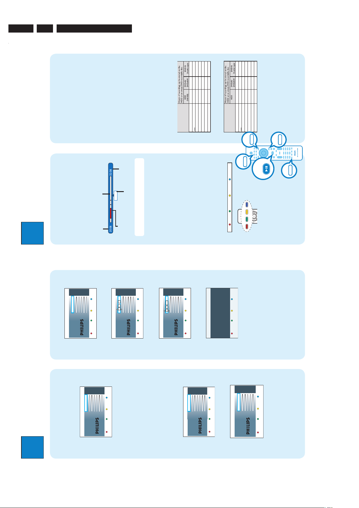
3
Enjoy
About the Time Shift Buffer
(TSB)
Once you turn on the recorder, the selected TV
programme will be stored in a temporary hard disk
storage called Time Shift Buffer ‘TSB’. The ‘TSB’ can
store up to 6 hours of programmes temporarily.
Press INFO to display the Time Shift video bar.
22:04:30
Note The contents in the time shift video bar will be
cleared when you press STANDBY ON (2).
Watch TV – Pause live TV
Your Philips Recorder allows you to control the TV
programme. You can PAUSE it as if you were in control
of the live broadcast.
A Turn on your recorder to the live TV mode and
press P +/- to select a TV programme.
B Press PAUSE LIVE TV to suspend it.
C Press PAUSE LIVE TV again to continue.
D To return to live broadcast, press LIVE TV.
Colour Softkeys function
Delete Copy Child Lock Protect
The colour functions shown on the
menu can be accessed by pressing the
matching colour coded buttons on the
remote control.
Current time
of playback
Selected clips for
recording
Programmes
stored in the ‘TSB’
Start time of the
programme
Present time
Satellite dish/
Cable TV wall outlet
PAUSELIVETV
Television ( rear)
D Press OK to start automatic analogue channel
search.
Previous Skip
Channel search
Start Auto search
E Once complete, press the Green button to
continue.
Previous Next
Time setting is required for
making recordings.
Time
00
00
:
AM
F Enter the correct time in the entry field and press
OK to confirm.
Previous Next
Date setting is required to
make recordings. Please
make sure it is correct.
Date
31
01
2007
G Enter the correct date in the entry field and press
OK to confirm.
You have successfully completed the installation
of your recorder.
System is now ready for use.
Previous Done
Installataion Complete
H The installation is completed now, press the Green
button to close the menu.
EN 73139 785 32804 3.Directions For Use
3. Directions For Use
The following except of the Quick Use Guide serves as an introduction to the set.
The Complete Direction for the Use can be downloaded in different languages from the internet site of Philips Customer care Center:
www.p4c.philips.com
Page 8
EN 8 3139 785 328043. Directions For Use
2
Set up
A
Finding the viewing channel
A Press STANDBY-ON on the recorder.
B Turn on the TV.
You should see the installation menu.
Menu Language
English
Please select your language.
Denes the languages of all
on-screen menu displays.
Next
Simpl Chinese
Trad Chinese
C In case you don’t see the recorder’s setting menu,
press the Channel Down button on the TVs remote
control repeatedly (or AV, SELECT,
°
button) until
you see the menu. This is the correct viewing
channel for the recorder.
B
Start initial installation
Use the recorder’s remote control and follow the on-
screen instructions to complete the installation.
A Select the desired language for this recorder’s on-
screen menu display and press the Green button to
continue.
Country Selection
AUS Australia
Country selection is
important for TV channels
search.
Next
BMU American B..
PRC China
RC Taiwan
NZ New Zealand�
ROK K
orea
SGP Singapore
HK Hong Kong
Previous
B Select the country you live and press the Green
button to continue.
Previous Next
Select the appropriate TV shape
according to the TV you have
connected.
TV shape
4:3 Letterbox
4:3 Panscan
16:9 Widescreen
C Select the appropriate TV shape in the way you
want the wide-screen movies to be displayed and
press the Green button to continue.
3
Enjoy
About the Time Shift Buffer
(TSB)
Once you turn on the recorder, the selected TV
programme will be stored in a temporary hard disk
storage called Time Shift Buffer ‘TSB’. The ‘TSB’ can
store up to 6 hours of programmes temporarily.
Press INFO to display the Time Shift video bar.
Now
22:04:30
Note The contents in the time shift video bar will be
cleared when you press STANDBY ON (2).
Watch TV – Pause live TV
Your Philips Recorder allows you to control the TV
programme. You can PAUSE it as if you were in control
of the live broadcast.
A Turn on your recorder to the live TV mode and
press P +/- to select a TV programme.
B Press PAUSE LIVE TV to suspend it.
C Press PAUSE LIVE TV
again to continue.
D To return to live broadcast, press LIVE TV.
Colour Softkeys function
Delete Copy Child Lock Protect
The colour functions shown on the
menu can be accessed by pressing the
matching colour coded buttons on the
remote control.
Current time
of playback
Selected clips for
recording
Programmes
stored in the ‘TSB’
Start time of the
programme
Present time
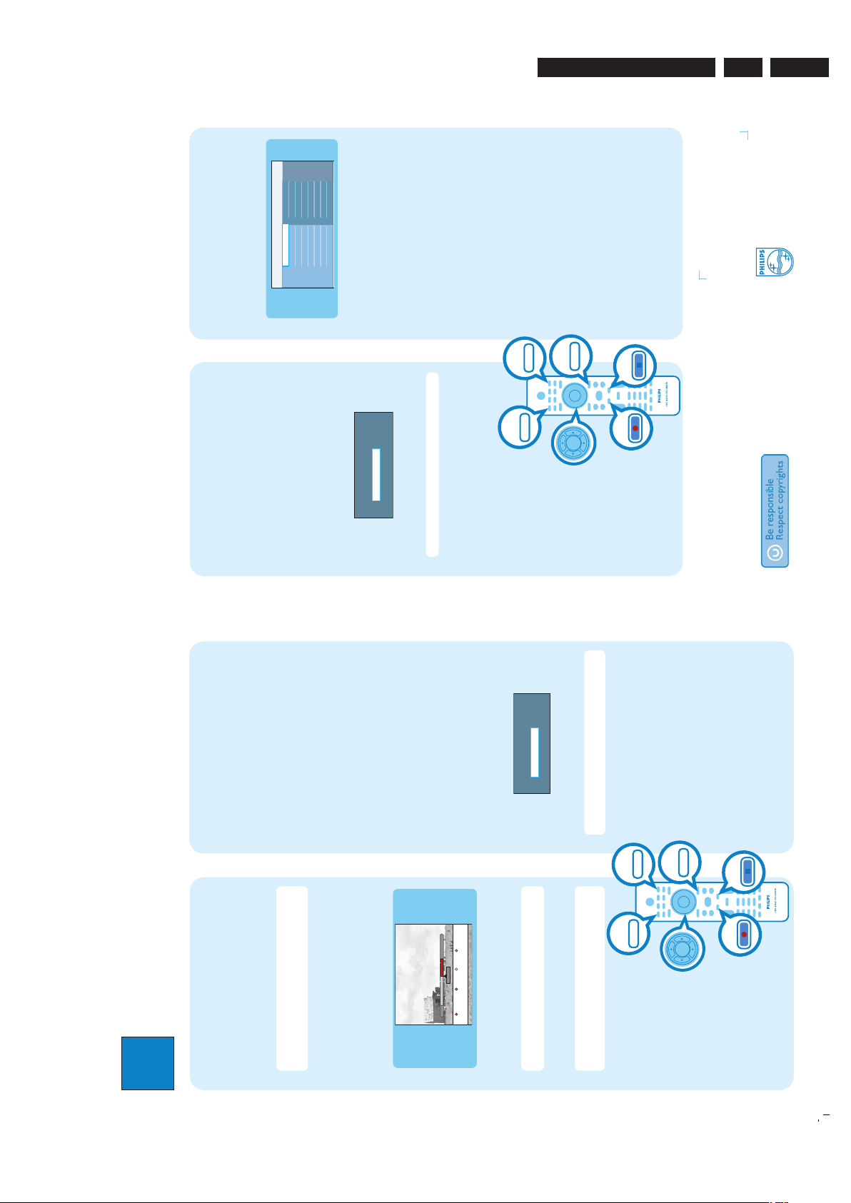
About the internal hard disk
drive
This recorder’s hard disk drive can be used as a Media
Jukebox, allowing you to store and playback your TV
programmes, videos, music and photos les.
Press HOME on the remote control to access your
contents stored in the { Hard Disk }.
Select a record mode
Select an appropriate recording mode is important as it
determines the picture quality and recording time to the
hard disk.
A Before recording, press OPTIONS on the
remote control.
B Select { Settings } in the menu and press OK.
C Move to { Recording } and press � right.
D Move to { Record mode } and press � right.
E Select a record mode and press OK to confirm.
DVDR3570H
Record Mode
HQ (high quality)
SP (standard play)
SPP (standard play plus)
LP (long play)
EP (extended play)
SLP (super long play)
SEP (super extended play)
122.53468
2345566890
135
180
1
hr 55 mins
3 hrs 40 mins
4 hrs 35 mins
5 hrs 30 mins
7 hrs 20 mins
11 hrs 5 mins
14 hrs 45 mins
DVDR3590H
Record Mode
HQ (high quality)
SP (standard play)
SPP (standard play plus)
LP (long play)
EP (extended play)
SLP (super long play)
SEP (super extended play)
122.53468
407796
115
153
230
300
1
hr 55 mins
3 hrs 40 mins
4 hrs 35 mins
5 hrs 30 mins
7 hrs 20 mins
11 hrs 5 mins
14 hrs 45 mins
(250GB)
INFO
HOME
LIVE TV
OPTIONS
PAUSE LIVE TV
D Press OK to start automatic analogue channel
search.
Previous Skip
Channel search
Start Auto search
E Once complete, press the Green button to
continue.
Previous Next
Time setting is required for
making recordings.
Time
00
00
:
AM
F Enter the correct time in the entry field and press
OK to confirm.
Previous Next
Date setting is required to
make recordings. Please
make sure it is correct.
Date
31
01
2007
G Enter the correct date in the entry field and press
OK to confirm.
You have successfully completed the installation
of your recorder.
System is now ready for use.
Previous Done
Installataion Complete
H The installation is completed now, press the Green
button to close the menu.
Page 9
3
Enjoy
Need help?
User Manual
See the user manual that came with your Philips Recorder
Online
Go to www.philips.com/welcome
2007 © Koninklijke Philips N.V.
All rights reserved.
12 NC 3139 245 27481
www.philips.com
Hard Disk / DVD Recorder
Quick Start Guide
What’s in the box?
Hard Disk/ DVD Recorder
RF antenna cable
(connect between
recorder and TV)
Audio/Video
cables
Record to hard disk
A
Record current TV programme
A Press REC to start recording. It can record up to
6 hours.
Note To set the recording time length, press REC
repeatedly to extend the recording time in 30-minute
increments, up to 6 hours.
B To stop the recording before the scheduled time,
press STOP.
B
Mark a speci c content in the Time
Shift Buffer for recording
23:30
22:13
21:00
Cancel Rec.
More Info
A Press left or right to search for the scene
where you want to record.
B Press REC
to start recording from here.
Note Pressing the Red button will cancel the
recording.
C Press right to search for the scene to end the
recording, then press STOP.
Note The title will be marked in red and the
recording will only take effect when you turn off the
recorder.
Copy TV programmes or les
A
Copy TV programmes from hard
disk
A Insert a recordable DVD into the recorder.
B Press HDD LIST on the remote control.
C Select a title to copy and press the Green button
on the remote control for { Copy }.
D The making disc copy information appears. Press
the Green button again to start copying.
B
Copy les from USB
You can only copy the data les (MP3, WMA, DivX and
JPEG) from your USB device to the recorder’s hard disk
drive or recordable DVD.
A Insert your USB device to the USB port at the front
panel of the recorder.
B Press USB on the remote control to view the
content menu.
C Use keys to reach the file you want to
copy.
D Press the Green button on the remote control for
{ Copy }.
Target for copy.
Choose destination for copy.
To Disc
To Hard Disk
E Select the destination for copying and press OK to
confirm.
Note If select { To Disc }, insert an empty
recordable DVD into the recorder.
F Press OK again to start copying.
HDD LIST
USB
REC
STOP
HOME
Start playback
A
Playback from hard disk
A Press HOME.
Disc Tray
USB
Recordings
Video les
Music
Photo
Source Content
Hard Disk
B Select { Hard Disk } and press right.
C Select the contents type and press right.
D Use keys to reach the title/file you want
to play and press u to start playback.
B
Playback from disc
A Hold down STOP until the disc tray opens. Load a
disc and close the disc tray.
B Press HOME and select { Disc Tray }.
C Use keys to reach the title/file you want
to play and press u to start playback.
C
Playback from USB device
A Insert the USB device to the USB port.
B Press USB to show the contents list.
C Select the contents type and press right.
D Select a data file
(MP3, WMA, DivX and JPEG)
and
press u to start playback.
C
Copy les from Disc
Copy prohibited contents cannot be copied to this
recorder.
A Insert a CD/DVD into the recorder.
B Press HOME and select { Disc Tray }.
C Use keys to reach the title/file you want to
copy.
D Press the Green button on the remote control for
{ Copy }.
Target for copy.
Choose destination for copy.
To USB
To Hard Disk
E Select the destination for copying and press OK to
confirm.
Note Only data les are able to copy to USB device.
F Press OK again to start copying.
HDD LIST
USB
REC
STOP
HOME
EN 93139 785 32804 3.Directions For Use
Page 10
EN 10 3139 785 328044. Mechanical Instructions
4. Mechanical Instructions
Note: The position numbers given here refers to the
Exploded view on chapter 8.
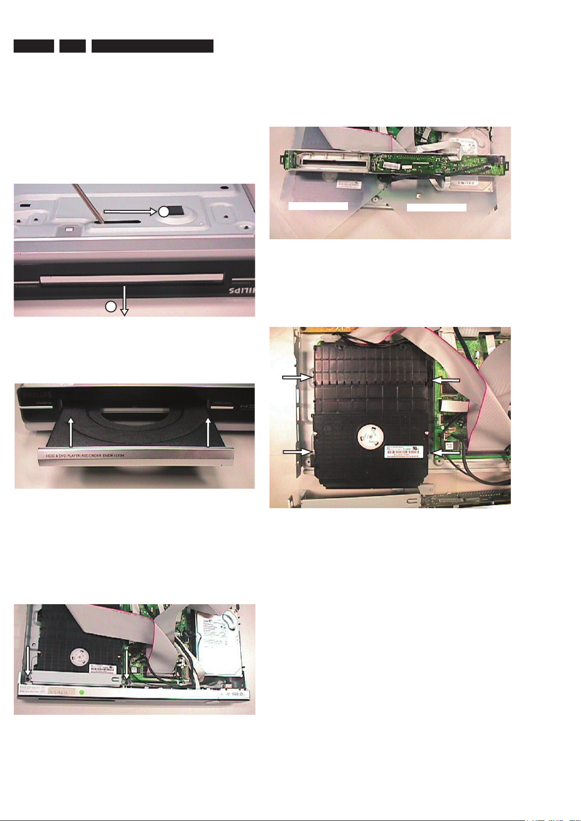
4.1 Dismantling of the DVD Tray cover manually
1) Insert a screwdriver into the slot provided at the bottom
of the set and push in the direction as shown in Figure1 to
unlock before sliding the Tray cover 110 out.
1
2
Figure 4-1: Unlock the tray loader
2) Remove the Tray cover 110 as shown in Figure 2.
Insulation Sheet
Figure 4-4: Front Panel Service Position
Insulation Sheet
4.3 Dismantling of the Basic Engine
1) Remove 4 mounting screws as shown in figure 5 to
dismantle the Basic Engine. 1007.
Figure 4-2: Remove the tray cover
4.2 Dismantling of the Front Panel
1) Remove 7 screws to loosen Top cover 240.
2) Remove 2 screws to loosen the Plate Front Loader 183
and detach the Front Cabinet Assembly P001 as shown
in Figure 3. The Front Panel Service Position is shown in
Figure 4.
Figure 4-3: Unscrew the screws to detach front panel
Figure 4-5: Basic Engine mounting screw
Page 11
EN 113139 785 32804 4.Mechanical Instructions
2) Flip the Basic Engine over to remove 4 screws from
the PCB protection plate. Service Position of the Basic
Engine is shown in Figure 6.
Insulation Sheet
Figure 4-6: Basic Engine Service Position
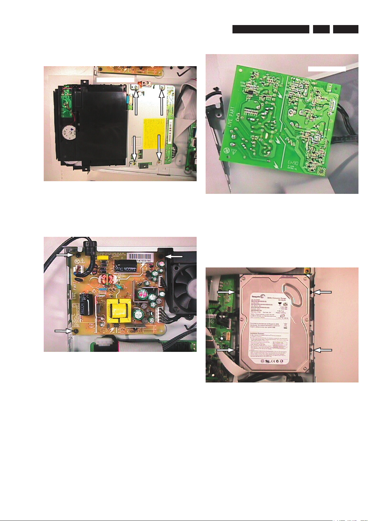
4.4 Dismantling of the PSU Board
1) Remove 3 screws to loosen the PSU Board 1004 as
shown in Figure 7.
2) Service position for PSU Board is given in Figure 8.
Insulation Sheet
Figure 4-8: PSU Board Service Position
4.5 Dismantling of the HDD
1) Remove 4 screws to loosen the HDD assembly (HDD
1005 and HDD Bracket 186 attached together by the
screws 271, for DVDR3590H there also includes HDD
Damper 191 and HDD Suspension Bracket 192) as
shown in figure 9.
Figure 4-7: PSU remove mounting screws
Figure 4-9: Remove mounting screws for HDD
2)
Flip over the HDD
271. Remove the screws to dismantle the HDD 1005 from
the HDD assembly
Notes: Only the special type of screws as described in
Service Parts List must be used for position number 271.
Using improper screws may damage the mounting holes on
the HDD.
.
Assembly to see the mounting screws
.
Page 12
EN 12 3139 785 328044. Mechanical Instructions
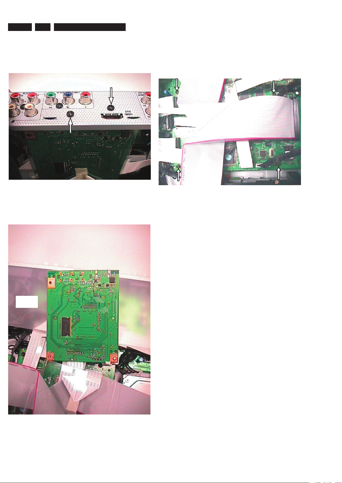
4.6 Dismantling of HDMI Board
1) Remove 2 screws to loosen the HDMI Board 1006 and
HDMI Shield 190 form the Rear Plate 230. The mounting
screws are shown in figure 10.
Figure 4-10: Remove mounting screws for HDMI Board
2) Remove the HDMI Shield 190 for HDMI Board Service
Position. The HDMI Board Service Position is shown in
figure 11.
4.7 Dismantling of the Digital Board
1) Remove the HDMI Board first, and remove the HDMI
Bracket 131 by unscrewing one screw.
2) Then remove 4 screws to loosen the Digital Board 1003
as shown in Figure 12.
Figure 4-12: Remove mounting screws for Digital Board
Insulation
Sheet
Figure 4-11: HDMI Board Service Position.
Page 13
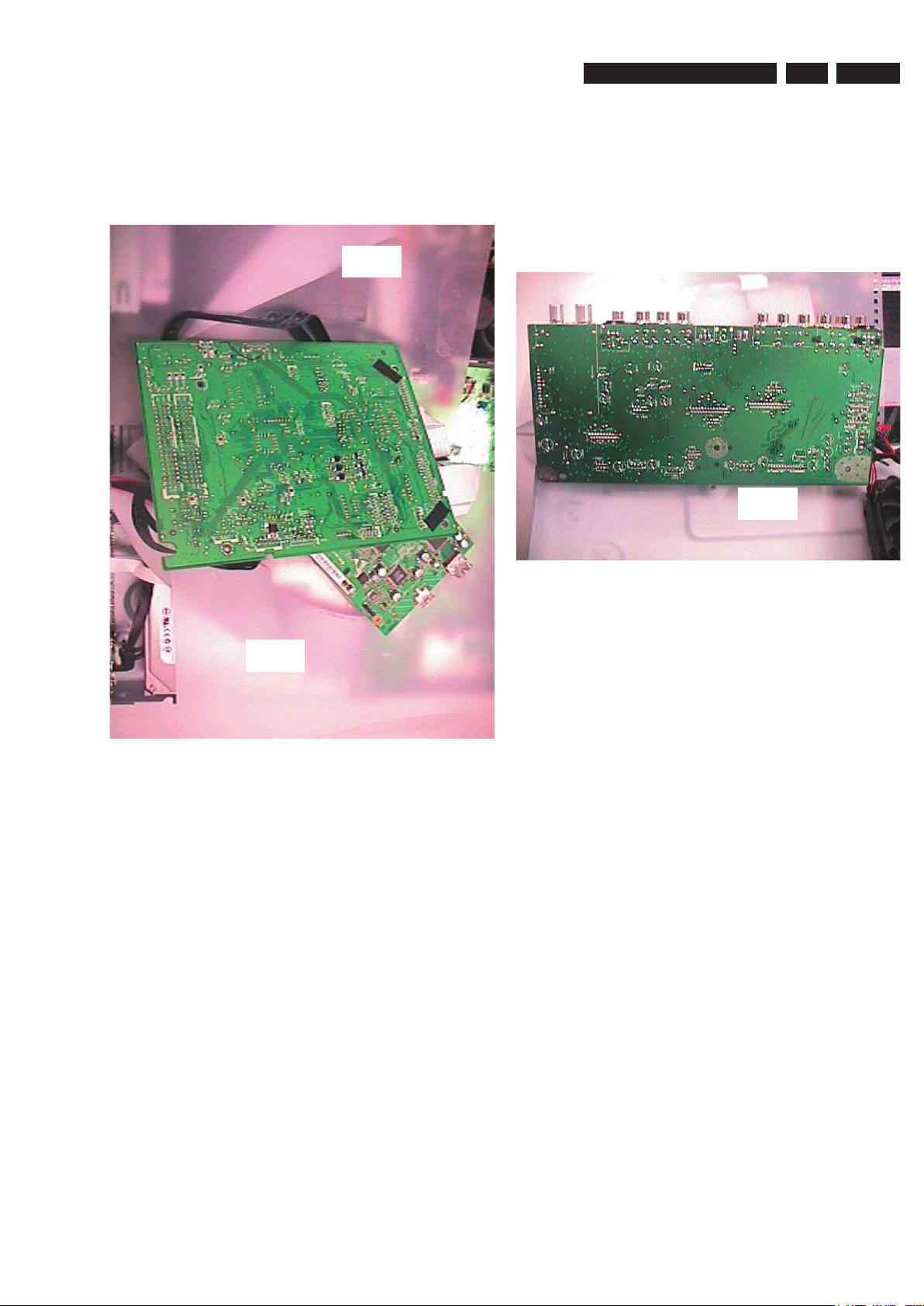
EN 133139 785 32804 4.Mechanical Instructions
3) Service position for Digital Board is given in Figure 13. (It
may be necessary to remove the Digital Board Bracket
187 and take out the cables beneath it to make it easier to
flip over the digital board. Put the insulation sheets under
the PC Boards. Refer to the set-wiring diagram in chapter
6 and make it sure to have the correct cable connections
among the PC Boards.)
Insulation
Sheet
4.8 Dismantling of the Analog Board
1) Remove the HDMI Board 1006 with its Shield 190 and
the HDMI bracket 189 first. Remove 3 screws that attach
the Analog Board 1001 to the Frame 161. Remove 6
more screws that attach the Analog Board 1001 to the
rear panel 230. Then dismantle the Analog Board. It may
be easier to dismantle the Analog Board if the rear panel
230 is detached first by removing 3 more screws.
2) Service position for Analogue Board is given in Figure 12.
Insulation
Sheet
Insulation
Sheet
Figure 4-13: Digital Board Service Position
Figure 4-14: Analogue Board Service Position (Rear Plate
230 detached)
Page 14

EN 14 3139 785 32804 Firmware Upgrading & Diagnostic Software5.
5. Firmware Upgrading and Useful Firmware Hints, Diagnostic
Software, Alignment and Test Procedures
5.1 Firmware Upgrading
5.1.1. Preparation to upgrade firmware
1. Unzip the zip-archive file
2. Start the CD Burning software and create a new CD project (data disc) with the following settings:
3. Place the content of the zip-archive into the root directory of the new CD project.
4. Burn the data onto a blank CDR or CD-RW
5.1.2. Procedure to apply the firmware upgrade:
Notes: There are 2 upgrade processes supported: - Normal Upgrade and Forced Download.
For normal upgrading, power up the set, open the tray, insert the upgrade disc, close the tray and follow the on screen
instruction. For forced download upgrading, follow the procedures described below.
1. Hold the <Record> + <Next> buttons down and Power up the set.
2. The tray opens and set will display:
DOWNLOAD −>……….PUT DISC
3. Insert the prepared Upgrade CDROM and close the tray.
4. The set will display:
INIT DSC −> DOWNLOAD −>……….
The whole process takes less than 10 minutes
Note: Do not press any buttons or interrupt the mains supply during the upgrading process, otherwise the set may
becomes defective.
5. When the upgrade is completed the tray will open automatically and the set will display:
REMOVE
6. Close the tray and the set will display:
DONE
Then the firmware upgrade process is completed successfully.
File system: Joliet
Format: MODE 2: CDROM XA
Recording mode: SINGLE SESSION (TRACK-AT-ONCE), FINALIZED CD
Note: Long file name is necessary for the preparation of the upgrade disc
5.1.3. How to read out the firmware version to confirm set has been upgraded:
Notes: In order to check the firmware version of the set, user version info screen should be accessed. Follow the
procedure below for checking user version info screen.
1. Power up the set
2. Press <OPTIONS> button on the Remote control and go to <Settings> option
3. Then go to <Setup> and choose <Version Info> by pressing OK.
4. The TV connected to the set will display the user version info as shown below for checking software version:
Version Info
Royal Philips
DVDR3570H
Software version: 01.00
Please visit our website
www.philips.com/support
for further software
updates and additional information
Developer name: Royal Philips
Product name (xxxx = model number): DVDRxxxxH (DVDR3570H in the example above)
Official SW release number: Software Version (xx.xx = release): xx.xx (01.00 in the example above)
5. Press <OPTIONS> button to exit.
Page 15

5.2. Procedure for checking Development Version Info Screen
Notes: For detail software information such as Slash Version, Drive Software Version, etc of the set,
the development version info screen should be accessed.
1) Power up the set
2) Press <OPTIONS> button on the Remote control and go to <Settings> option
3) Then go to <Setup> and choose <Version Info> by pressing OK.
4) When the user version info screen is appeared, press the blue key on the remote control.
5) The TV connected to the set will display the Development Version Info Screen as shown below:
Version Info
(c)PHILIPS 2006 Version Information:
DI L+06_7/751731 SV 11602
BE 52.07.02.15 ASP 1,18,1,10
C1_7 20070224_1659 pro lecoplusleadV2 <void>
EPG: DPMS:P_DPM
Digital Board Info: (DI: Digital Board, L+06_7: Digital Board name, 75: Hardware ID for EU Non EPG, 1731: SW
BUILD ID for recorder application in the example)
Slash Version (xxxxx = version): SV xxxxx (11602 for /51 in the example above)
Drive SW Version (yy.yy = model, xx.xx = version): BE yy.yy.xx.xx (Model 52.07, Version 02.15 in the example)
ASP Software and VFD Driver Version Number: (1,18: ASP software version number, 1,10: version number of
VFD Driver
Detailed Build Information: (C1_7: Branch Information, 2007: year, 02: month, 24: date, 16: Hour, 59: minute in
the above example)
EPG: DPMS:P_DPM (internal to the recorder application.)
EN 153139 785 32804 5.Firmware Upgrading & Diagnostic Software
5.3 Procedure for Formatting HDD drive
1) Press and Hold the <Previous> + <Stop> key combination while powering on the mains.
2) The set will start to display “FMT KEY”, and then it will show “FMT HDD” while formatting HDD.
3) If the formatting is completed successfully, the set will display “FMT DONE”. If the formatting is failed, it will show “FMT FAIL”
Notes: Do not power off the set immediately when the “FMT DONE” is seen. Wait until the time or - - : - - is displayed before powering
off the set.
5.4. Procedure to Virginize the set
Notes: All the user information will be lost after virginizing the set. Follow the procedure below to virginize the set.
1) Press and hold down the Standby key on the front while connecting to the power outlet.
2) Release the keys when the scrolling messages appear on VFD.
3) Press standby key again and follow the instructions when the set wakes up.
5.5 HDD replacement procedure.
When a defective HDD is replaced by a brand new HDD,
1. Install the new HDD.
2. Upgrade the software (forced download) with the upgrade disc to the latest software (follow the procedures described in 5.1.2)
3. Format the HDD (follow the procedures described in 5.3)
Then the HDD is ready to use. Some of the user information may be lost after HDD Replacement.
Page 16
EN 16 3139 785 32804 Firmware Upgrading & Diagnostic Software5.
Diagnostic Softwa re
D ue to the co mplexity of the DVD rec order, the time to find a
de fect in the rec order can become long. To r educe this ti me ,
th
e recorder has been equipped wi th D iagn ostic and Serv ice
so
ft ware (DS ). Th e DS o ff ers functionali ty t o diagnose the
DV
DR hardware and te st s th e fo ll owing:
• I
nterconnec tions between co mponent
s
• A
cc essibility of com ponents
•
F unctionality of the audio and video paths
Th
is f unc tionalit y ca n be acces sed via se veral in terf aces :
1.
End user/Dealer script interfa ce
2.
Comm and Inte rfac
e
Fi
gu re 5-1
Th
e En d use/Dealer scr ip t ex ecutes all diagnostic nuc lei t ha t
do
not ne ed any use r interaction and are meaningful on a
st
andalone DV D re corder.
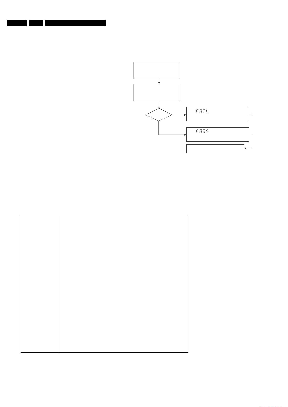
Hold k ey <PLAY> pressed
while you plug the recorder
Unplug the power cord
SET O.K.?
YE S
NO
To ex it DEALER SCRIPT, unplug th e power cord
During the test, the display will show
the a sequence of nuclei under test
TR 18029_001
12
0304
The End user/Dealer script interface gives a diagnosis on a
stand alone DVD recorder. During this mode, a number of
ha
rdware tests (nuclei) are automatically executed to check if
the recorder is faulty. Th
e diagnosis is simply a "fail" or "pass"
m
essage. If the message "FAIL" appears on the display, there
i
s apparently a failure in the recorder. If the message "PASS"
ap
pears, the nuclei in this mode have been executed
su
ccessfully. There can be still a failure in the recorder
be
cause the nuclei in this mode do not cover the complete
functionality of the recorder.
I
n
cluded tests:
1. DS_CHR_DEVTYPEGET_NUC
2. DS_SDRAM_WRITEREADFAST_NUC
3. DS_FLASH_DEVTYPEGET_NUC
4. DS_FLASH_CHECKSUMPROGRAM_NUC
5. DS_VIP_COMMUNICATION_NUC
6. DS_VIP_DEVTYPEGET_NUC
7. DS_DVIO_LINKDEVTYPEGET_NUC
8. DS_DVIO_PHYCOMMUNICATION_NUC
9. DS_DVIO_PHYDEVTYPEGET_NUC
10. DS_BE_COMMUNICATIONECHO_NUC
11. DS_BE_VERSIONGET_NUC
12. DS_SYS_HARDWAREVERSIONGET_NUC
13. DS_SYS_SOFTWAREVERSIONBOOTGET_NUC
14. DS_SYS_SOFTWAREVERSIONDOWNLOADGET_NUC
15. DS_SYS_SOFTWAREVERSIONAPPLGET_NUC
16. DS_SYS_DVIDNUMBERGET_NUC
17. DS_SYS_SLASHVERSIONGET_NUC
18. DS_SYS_SETTINGSDISPLAY_NUC
19. DS_SYS_BUILDINFOGET_NUC
20. DS_ASP_COMM_NUC
21. DS_ASP_VERSION_NUC
22. DS_FRE_COMM_NUC
23. DS_HDD_COMMUNICATION_NUC
24. DS_HDD_VERSION_NUC
25. DS_USB_DEVTYPEGET_NUC
5.6 End User/Dealer Script Interface
5.6.1 Description
5.5.2 Structure
5.
6.2 Contents
Page 17
22 DTTM*
23 USB
5.7 Menu and Command Mode Interface
5.7.1 Nuclei Numeration
Each nucleus has a unique number of four digits. This number
is
the input of the command mode.
Figure 5-2
Gr
oup number Group name
[ XX YY ]
Nucleus number
Nucleus group number
CL 06532152_012.eps
051200
5.7.3 Command Mode Interface
Se t-Up Physical Interface Component s
Har dware required:
• S ervice P
C
• o
ne free CO M po rt on the Serv ic e PC
• s
pecial c able to c onnect D VD re corder to Ser vice PC
Th
e ser vice PC must have a terminal em ul at ion program (e.g.
Hy
perterminal) in stalled and mu st hav e a fr ee C OM port ( e.g.
CO
M1 ). A ctiv at e the te rm inal em ulation program and chec k
th
at the port s ettings for th e free CO M por t are: 19200 bps, 8
da
ta bit s, no pa rity, 1 s top bit a nd no flow c ontro l. T he fr ee C OM
po
r t mus t be c onnected via a s pecial c able to the RS 232 port
of
the DVD recor der. Thi s s pecial ca bl e will also connec t the
te
st pin, which is available on the connec tor , t o ground (i.e.
ac
tivat e test pin).
C
ode number of PC interface cable : 3122 785 90017
Act ivation of Diagnostic Software
1. Pu ll the ma ins co rd from t he re corder and reconnec t it
a gai n (reboo t) .
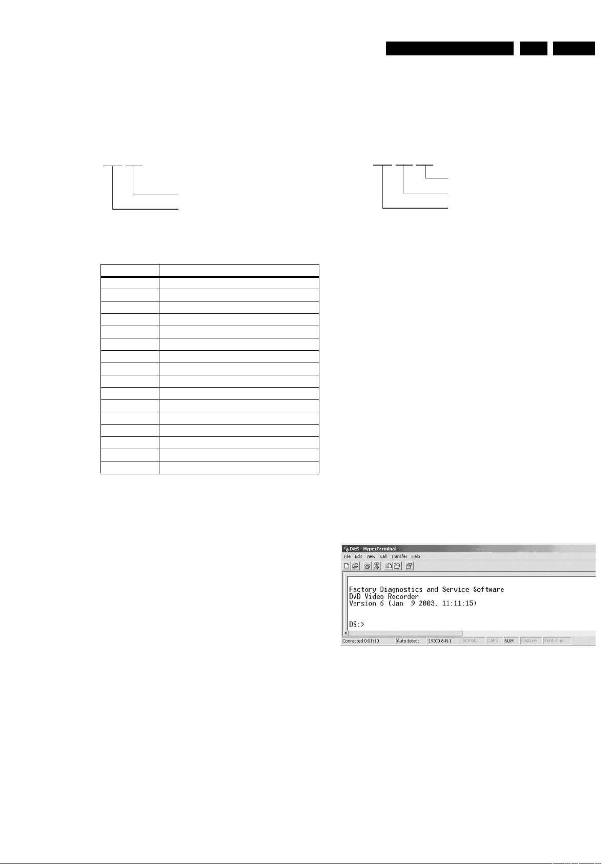
2.
The next welc ome mes sage wi ll a ppear on t he PC
:
We
lcome screen D&S program
F
i gu re 5-4
No
w , the prom pt 'DS :>' wil l appear . The diagnostic software is
no
w ready t o re ceive comm ands. The com mands t hat can be
gi
ve n are th e num bers of the nuclei. If you see above shown
sc
reen, c ontinue with para
g
raph 'Nuclei Cod es'.
5.7.2 Error Handling
Ea ch nucleus returns an er ror code. This c ode c ontains six
nu
m erals, w hi ch m eans:
F
i gu re 5-3
T
he nucleus group number s an d nuc leus num bers are the
sa
me as above.
[ XX YY ZZ ]
Error code
Nucleus number
Nucleus group numbe r
CL 06532152_013.ep s
05 12 00
1 Codec (e.g. LeCo+)
0 Scripts
2 Boot EEPROM*
3 NVRAM (EEPROM of FLASH)*
4 SDRAM (or DDR-RAM)
5 FLASH
6 Video Input Processor
7 DVIO
9 Basic Engine
12 System
15 HDMI
16 Analogue Slave Processor
20 F
ront End
21 Hard Disk
* Not applicable for DVDR3570H,
EN 173139 785 32804 5.Firmware Upgrading & Diagnostic Software
Page 18
EN 18 3139 785 32804 Firmware Upgrading & Diagnostic Software5.
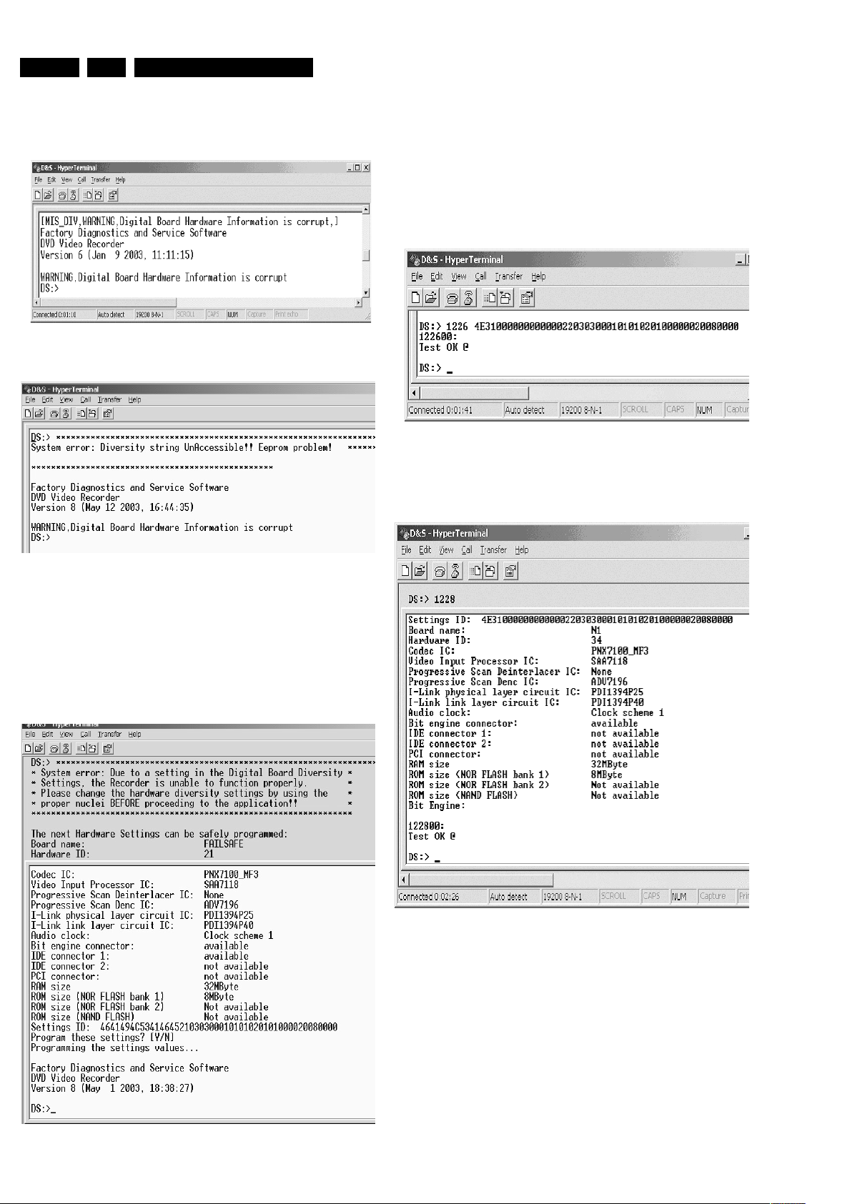
3. It is possible that the next messages will appear when
starting the DVD+RW for the first time
Er
ror messages D&S program
Figure 5-5a
Er
ror messages D&S program
Figure 5-5b
In these cases, t
he boot EEPROM of the Digital Board does not
contain the required string with the hardware information. To
u
pdate the Digital Board with the correct string, nucleus 1226
m
ust be executed.
See next section 'Diversity S
tring Input'.
There can also be the next error m
essage.
Figure 5-5c
Enter "Y" to program a safe string. With this automatically
g
enerated string the board will wo
rk in principle but it has to be
checked if all board settings were detected correctly.
Diversity String Input
4. Execute nucleus 1226 to enter the string. Please see
chapter 8 for details
Nucleus 1226 execution with string
Figure 5-6
5
. To check if t
he hardware info is filled correctly, you can
execute nucleus 1228.
Nucleus 1228 info example
F
igure 5-7
6
. Exit t
he 'Terminal' program.
7. Reboot the DVD recorder t
o allow the software to start.
Page 19

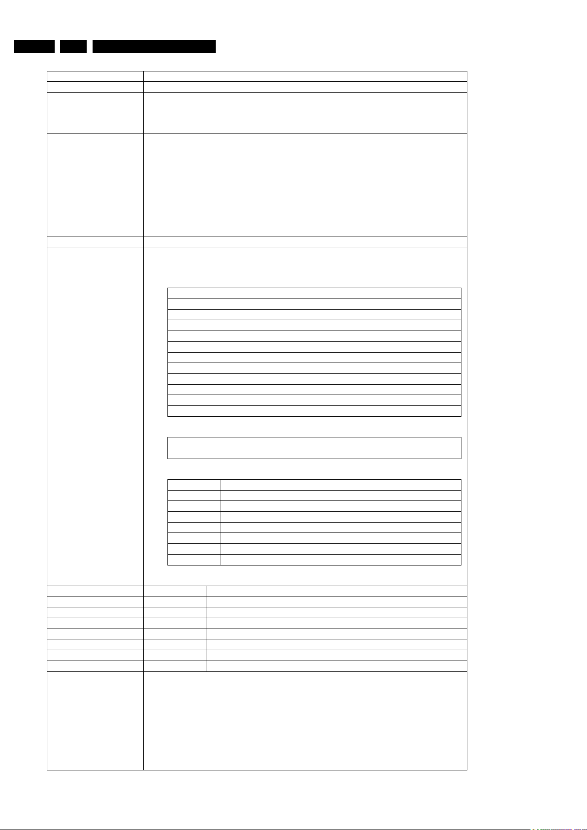
Command overview Digital Board
Nucleus Name
DS_CHR_DevTypeGet
Nucleus Number 100
Description Retrieves the device id, the module ids and revisions of the Codec and returns
them to the stdout port.
Technical - Determine the codec id by means of comparing version ids of the modules.
- Read the module-id register of every module and display it to the user.
Execution Time Less than 1 second.
User Input None
Error Number Description
10000 Getting the information succeeded
10001 Wrong codec id detected
Example
DS:> 100
010000:
Device ID 7300
Codec ID PNX7350
F-BCU (0x0102) 4.0 INTC (0x011d) 3.0
SIF (0xa04b) 2.0
BOOT (0x010a) 3.1 CONFIG (0x013f) 5.0 RESET (0x0123) 5.0
CLOCK (0x013e) 7.0 DEBUG (0x0116) 0.1 UART0 (0x0107) 1.2
UART1 (0x0107) 1.2
I2C0 (0x0105) 0.1 I2C1 (0x0105) 0.1 GPIO (0x013c) 3.1
SYNC (0x013a) 4.0
OSD (0x0136) 1.0 SPU (0xa00e) 1.1 MIXER (0x0137) 3.0
DENC (0x0138) 5.0 CCIR (0x0139) 2.1 VDEC (0x0133) 1.0
PARSER (0xa00d) 0.0 DV (0xa00c) 0.0
IDE0 (0xa009) 1.2 IDE1 (0xa009) 1.2 SGDX (0xa008) 4.0
BYTE (0xa00b) 1.0 OUTPUT (0xa003) 8.0 ACOMP (0xa000) 8.0
VFE (0xa001) 8.0 VCOMP (0xa002) 8.0 SCR (0xa004) 8.0
SIFF (0xa011) 3.0
PSCAN (0xa05d) 0.1
ADEC (0x0134) 1.1 IR (0x0131) 2.0 AOI (0xa08c) 0.0
PIP (0xa04d) 1.0 AVLINK (0x3601) 2.1 USBLINK(0xa08e) 0.0
MSVD (0xa087) 0.0 FEBCU (0xa05e) 1.0 BM (0xa085) 0.0
BMI (0xa084) 0.0 DISP (0xa04d) 1.0
Test OK @
Below you will find an overview of the nuclei, their numbers,
and their error codes. This overview is preliminary and
subject to modifications.
Codec Host Controller (CHR)
EN 193139 785 32804 5.Firmware Upgrading & Diagnostic Software
Page 20
EN 20 3139 785 32804 Firmware Upgrading & Diagnostic Software5.
Nucleus Name
DS_CHR_TestImageOn
Nucleus Number 101
Description Generates a test-image of a selected video standard on selected video output
on the digital board. When no input is given, the default values will be used (see
user input description below). Make sure to use the proper nuclei to route the
video signal on the VIP to get the video signal to the proper output.
Technical - Validate the user input.
- Initialise the SYNC module.
- Initialise the DISPLAY module.
- Initialise the MIXER module.
- Initialise the DENC module.
- Set the selected video standard.
- Generate the selected test image in memory.
- Start the DISPLAY module.
- Start the MIXER module.
- Start the DENC module according t
o the selected test image id.
Execution Time 6 seconds.
User Input The user has to decide which test image, video standard and video output must
be used: < Test image id > < Video standard > < Video output >
Test image id:
0 VERTICAL_COLOURBAR (default)
1 HORIZONTAL_COLOURBAR
2 WHITE
3 YELLOW
4 CYAN
5 GREEN
6 MAGENTA
7 RED
8 BLUE
9 BLACK
10 GRAY
11 TEST_IMAGE_FOR_PROGRESSIVE_SCAN
Video standard:
PAL Standard PAL 50 Hz (default)
NTSC Standard NTSC 60 Hz
Video output:
ALL CVBS and YC and RGB signals are enabled (default)
ALL_RGB CVBS and YC and RGB signals are enabled (default)
ALL_YUV CVBS and YC and YUV signals are enabled
CVBS CVBS signal is enabled
YC YC signal are enabled
RGB CVBS, and RGB signals are enabled
YUV YUV signals are enabled
PSCAN Progressive scan is enabled
Error Number Description
10100 Generating the test image succeeded.
10101 Invalid input was provided.
10102 The Codec SYNC-module cannot be initialised.
10103 The Codec MIXER-module cannot be initialised.
10104 The Codec VPP-module cannot be initialised.
10105 The Codec DENC-module cannot be initialised.
10106 The digital board hardware information is corrupt
Example
DS:> 101
010100:
Test OK @
DS:> 101 0 pal cvbs
010100:
Test OK @
DS:> 101 4 ntsc yc
010100:
Test OK @
Page 21
EN 213139 785 32804 5.Firmware Upgrading & Diagnostic Software
Nucleus Name
DS_CHR_TestImageOff
Nucleus Number 102
Description Switches the test-image off.
Technical - Stop the DENC module.
Execution Time Less than 1 second.
User Input None
Error Number Description
10200 Stopping the test image generation succeeded
10201 The Codec DENC-module failed.
Example
DS:> 102
010200:
Test OK @
Nucleus Name
DS_CHR_SineOn
Nucleus Number 103
Description Generate an audio sine signal on the audio output of the digital board.
Note: Left channel 6kHz, right channel 12 kHz sine. Make sure to route the
signal first.
When ‘SPDIF’ is entered as a parameter, the SPDIF path will be activated
correctly to generate a PCM sine wave on the digital audio output.
Technical - De-mute the analogue board
- Set fifo parameters for audio
- Set the volume
- Set the I2S outputs and configuration paths
- Set the decoder mode
- Configure the audio decoder
- Put the AC3 audio in the fifo
- Send ‘prepare’ command to the audio decoder
- Send ‘play’ command to the audio decoder
Execution Time Less than 1 second
User Input None or ‘SPDIF’
Error Number Description
10300 The sine signal was successfully generated
10301 The analogue board could not be de-muted
10302 The audio decoder did not initialise
10303 The dsp2 (DUET) of the audio decoder did not configure
10304 The dsp1 (PALM) of the audio decoder did not configure
10305 There was a delay-error before starting
10306 Wrong input was given to the decoder function
10307 Wrong input was given to the decoder function @@@@@
10308 The audio decoder did not get into the ‘prepared’ state
Example
DS:> 103
010300:
Test OK @
DS:> 103 spdif
010300:
Test OK @
Nucleus Name
DS_CHR_SineOff
Nucleus Number 104
Description Stop generating the audio sine signal
Technical - Reset the audio block of the Codec
Execution Time Less than 1 second.
User Input None
Error Number Description
10400 Switching off the audio sine signal succeeded
10401 Failed to reset the audio decoder
Example
DS:> 104
010400:
Test OK @
家电维修资料网,免费下载各种维修资料
Page 22
EN 22 3139 785 32804 Firmware Upgrading & Diagnostic Software5.
Nucleus Name
DS_CHR_SineBurst
Nucleus Number 105
Description Generate an audio sine signal on the audio output of the digital board for 4
seconds.
Note: Left channel 6kHz, right channel 12 kHz sine with some known hick-ups
Technical - Call the DS_CHR_SineOn nucleus
- Delay for 4 seconds
- Call the DS_CHR_SineOff nucleus
Execution Time 4 seconds
User Input None
Error Number Description
10500 The sine signal burst was successfully generated
10501 The delay did not succeed during the burst
10502 The audio sine could not be generated
Example
DS:> 105
010500:
Test OK @
Nucleus Name
DS_CHR_MuteOn
Nucleus Number 106
Description Mute the audio outputs of the digital board
Technical - Send the ‘Mute’ command to the audio decoder
- Activate the ‘audio mute’ PIO pin
Execution Time Less than 1 second.
User Input “PIO” to just use the PIO pin mute. When muting using this, also de-mute using
this as this works ‘paired’.
Error Number Description
10600 Muting the audio succeeded
10601 Muting the audio through the PIO-pin failed
Example
DS:> 106
010600:
Test OK @
DS:> 106 PIO
010600:
Test OK @
Nucleus Name
DS_CHR_MuteOff
Nucleus Number 107
Description De-mute the audio outputs of the digital board
Technical - Send the ‘DeMute’ command to the audio decoder
- Deactivate the ‘audio mute’ PIO pin
Execution Time “PIO” to just use the PIO pin de-mute. Only de-mute using this when you muted
using the PIO parameter, as this works ‘’paired.
User Input None
Error Number Description
10700 De-muting the audio succeeded
10701 De-muting the audio through the PIO-pin failed
Example
DS:> 107
010700:
Test OK @
DS:> 107 PIO
010700:
Test OK @
http://www.jdwxzlw.com/?fromuser=华盛维修
家电维修资料网,免费下载各种维修资料
Page 23
EN 233139 785 32804 5.Firmware Upgrading & Diagnostic Software
Nucleus Name
DS_CHR_MacroVisionOn
Nucleus Number 110
Description Turn on MacroVision.
Technical - Set some registers of the DENC module in the Codec.
Execution Time Less than 1 second.
User Input None
Error Number Description
11000 Turning on MacroVision succeeded
11001 Turning on MacroVision failed
Example
DS:> 110
011000:
Test OK @
Nucleus Name
DS_CHR_MacroVisionOff
Nucleus Number 111
Description Turn off MacroVision.
Technical - Set some registers of the DENC module in the Codec.
Execution Time Less than 1 second.
User Input None
Error Number Description
11100 Turning off MacroVision succeeded
11101 Turning off MacroVision failed
Example
DS:> 111
011100:
Test OK @
Nucleus Name
DS_CHR_Peek
Nucleus Number 112
Description Peek a value on a specified address
Technical - Check the user input
- Read out the address specified
- Check whether the address to be read is aligned on 4 bytes
Execution Time Less than 1 second.
User Input The address to peek on
Error Number Description
11200 Peeking on the specified address succeeded
11201 Peeking on the specified address failed, wrong user input
11202 Peeking on the specified address failed due to misalignment
Example
DS:> 112 0xa0700000
011200: Value read = 0x000001BD
Test OK @
Nucleus Name
DS_CHR_Poke
Nucleus Number 113
Description Poke a value on a specified address
Technical - Check the user input
- Change the value on the address specified
- Check whether the address to be modified is aligned on 4 bytes
Execution Time Less than 1 second.
User Input The address to poke and the value: <address><value>
Error Number Description
11300 Poking the specified address succeeded
11301 Poking the specified address failed, wrong user input
11302 Poking the specified address failed due to misalignment
Example
DS:> 113 0xa0700000 0xaabbccdd
011300:
Test OK @
http://www.jdwxzlw.com/?fromuser=华盛维修
家电维修资料网,免费下载各种维修资料
Page 24

EN 24 3139 785 32804 Firmware Upgrading & Diagnostic Software5.
Nucleus Name
DS_CHR_INT_PICInterrupts
Nucleus Number 114
Description Test all interrupts of the priority interrupt controller
Technical - Install interrupt handlers
- Generate interrupts
- Test whether all interrupts were received
Execution Time Less than 1 second.
User Input Error Number Description
11400 Testing all the PIC interrupts succeeded
11401 Testing all the PIC interrupts failed
Example
DS:> 114
011400:
Test OK @
Nucleus Name
DS_CHR_DMA_TestDMA
Nucleus Number 115
Description Test the memory to memory DMA transfer
Technical - Create a block with known data in memory
- Copy this block to the consecutive area using 4 different DMAs
- Check whether all DMAs transferred the data properly
Execution Time Less than 2 seconds.
User Input Error Number Description
11500 The testing of the DMAs succeeded
11501 The initialisation of the DMAs failed for one or more DMA
11502 One or more DMAs failed the test
Example
DS:> 115
011500:
Test OK @
Nucleus Name
DS_CHR_PioGet
Nucleus Number 116
Description Get a value from a PIO pin
Technical - Decode user input
- Read the PIO input register of the cod
ec and return the requested pio line
value
Execution Time Less than 1 second.
User Input <PIN>
where PIN is the pio pin to get (0..31)
Error Number Description
11600 Getting PIO value succeeded
11601 Invalid parameter
Example
DS:> 116 15
011600: Value read = 0x1
Test OK @
http://www.jdwxzlw.com/?fromuser=华盛维修
家电维修资料网,免费下载各种维修资料
Page 25
EN 253139 785 32804 5.Firmware Upgrading & Diagnostic Software
Nucleus Name
DS_CHR_PioSet
Nucleus Number 117
Description Set a value on a PIO pin. Make sure that the pin is configured as output first
Technical - Decode user input
- Update the PIO output register of the codec
Execution Time Less than 1 second.
User Input <PIN> <VALUE>
where PIN is the pio pin to set (0..31)
and VALUE the value of the pin (0..1)
Error Number Description
11700 Setting PIO value succeeded
11701 Invalid parameter
Example
DS:> 117 15 0
011700:
Test OK @
Nucleus Name
DS_CHR_PioConfig
Nucleus Number 118
Description Configure a PIO pin
Technical - Decode user input
- Update the PIO configuration
register of the codec
Execution Time Less than 1 second.
User Input <PIN> <DIR>
where PIN is the pio pin to set (0..31)
and DIR the direction of the pin (0=IN 1=OUT)
Error Number Description
11800 Setting PIO configuration succeeded
11801 Invalid parameter
Example
DS:> 118 14 0
011700:
Test OK @
http://www.jdwxzlw.com/?fromuser=华盛维修
家电维修资料网,免费下载各种维修资料
Page 26

EN 26 3139 785 32804 Firmware Upgrading & Diagnostic Software5.
SDRAM (SDRAM OR DDR-RAM)
Nucleus Name
DS_SDRAM_WriteRead
Nucleus Number 400
Description Check all data lines, address lines and memory locations of the RAM
Technical - Test the data bus
- Test the address bus
- Test the integrity of the device itself (memory locations)
Execution Time 11 seconds for 32 Mb
23 seconds for 64 Mb
User Input None
Error Number Description
40000 The write-read test succeeded
40001 The data bus contains an error
40002 The address bus contains an error
40003 The RAM itself contains an error
Example
DS:> 400
040000:
Test OK @
Nucleus Name
DS_SDRAM_WriteReadFast
Nucleus Number 401
Description Check all data lines and address lines of the RAM
Technical - Test the data bus
- Test the address bus
Execution Time Less than 1 second
User Input None
Error Number Description
40100 The write-read test succeeded
40101 The data bus contains an error
40102 The address bus contains an error
Example
DS:> 401
040100:
Test OK @
Nucleus Name
DS_SDRAM_Write
Nucleus Number 402
Description Write to a specific un-cached memory address
Technical - Decode the user input and check its ranges and alignment on 4 bytes
- Write the data to the RAM
Execution Time Less than 1 second
User Input 1. The location that must be modified
(RAM starts at address 0xA0000000)
2. The value to put on the selected location
Error Number Description
40200 Writing to the RAM succeeded
40201 Writing to the RAM failed; Wrong user input
40202 Address is not dividable by 4
Example
DS:> 402 0xa1000010 0xad112222
040200:
Test OK @
http://www.jdwxzlw.com/?fromuser=华盛维修
家电维修资料网,免费下载各种维修资料
Page 27
EN 273139 785 32804 5.Firmware Upgrading & Diagnostic Software
Nucleus Name
DS_SDRAM_Read
Nucleus Number 403
Description Read from a specific un-cached memory address
Technical - Decode the user input and check the ranges
- Read from the RAM and return this info to the user
Execution Time Less than 1 second
User Input The location from which the data must be read
(RAM starts at address 0xA0000000)
Error Number Description
40300 Reading from the RAM succeeded
40301 Reading from the RAM failed; Wrong user input
40302 Address is not dividable by 4
Example
DS:> 403 0xa1000010
040300: Value read = 0xAD112222
Test OK @
Nucleus Name
DS_SDRAM_DmaWriteRead
Nucleus Number 404
Description Write a pattern to the entire RAM using DMA and check the data
Technical - Check if the Stack pointer is not in the write range
- Clear a 64kb block and then fill it with a pattern
- Initialise the DMA controller and write the data to the SDRAM
- Then check if all the data was written correctly (except descriptor tables)
- Repeat the process 4 times with 4 different patterns
Execution Time 24 seconds
User Input None.
Error Number Description
40400 Writing to the RAM succeeded
40401 Stack area definition ERROR!
40402 DMA controller could not be initialised.
40403 Not all data was transferred correctly
Example
DS:> 404
040400:
Test OK @
http://www.jdwxzlw.com/?fromuser=华盛维修
家电维修资料网,免费下载各种维修资料
Page 28
EN 28 3139 785 32804 Firmware Upgrading & Diagnostic Software5.
FLASH (FLASH)
Nucleus Name
DS_FLASH_DevTypeGet
Nucleus Number 500
Description Get the device (revision) type information of the FLASH ICs. (type,
manufacturer, device ID and size)
Technical - Set the timing for the flash writing
- Write a command sequence to determine device type information
- Return the information to the user
Execution Time Less than 1 second
User Input None
Error Number Description
50000 Getting the information from the FLASH succeeded
50001 Getting the information from the FLASH failed
Example
DS:> 500
050000: Found FLASH memory:
NOR AMD 29DL640G 8MB,NOR AMD 29DL640G 8MB
Test OK @
Nucleus Name
DS_FLASH_Read
Nucleus Number 502
Description Read from a specific memory address in FLASH
Technical - Decode the user input and check the ranges and whether the address is
aligned on 4 bytes
- Read the data and return this to the user
Execution Time Less than 1 second.
User Input The location from which data must be read
(FLASH starts at address 0xB8000000)
Error Number Description
50200 Reading the FLASH succeeded
50201 Reading the FLASH failed; Wrong user input
50202 Address is not dividable by 4
Example
DS:> 502 0xb8000000
050200: Value read = 0x3C08A000
Test OK @
Nucleus Name
DS_FLASH_ChecksumProgram
Nucleus Number 503
Description Check the checksum of the application partitions by recalculating and
comparing partition checksums
Technical - Determine the number of segments
- Find the application in each segment and determine its checksum
- Check whether the checksums stored match the newly calculated
Execution Time 6 seconds
User Input None
Error Number Description
50300 The checksum is valid, the test succeeded
50301 The checksum is invalid
Example
DS:> 503
050300:
BootCode checksum is: 0xBABE5B6F, which is correct
Diagnostics checksum is: 0xBABEBAFF, which is correct
Download checksum is: 0xBABEEDBF, which is correct
Application checksum is: 0xBABE8EEC, which is correct
Test OK @
http://www.jdwxzlw.com/?fromuser=华盛维修
家电维修资料网,免费下载各种维修资料
Page 29
EN 293139 785 32804 5.Firmware Upgrading & Diagnostic Software
Nucleus Name
DS_FLASH_CalculateChecksum
Nucleus Number 504
Description Calculate the checksum over all memory addresses. Used to check entire
FLASH contents
Technical - Run the checksum calculation algorithm on all flash memory addresses
Execution Time 6 seconds
User Input None
Error Number Description
50400 Calculating the checksum over all addresses succeeded
Example
DS:> 504
050400: The Checksum = 0xBABE30A4
Test OK @
Nucleus Name
DS_FLASH_CalculateChecksumFast
Nucleus Number 505
Description Calculate a checksum over a selected number of address locations
Technical - Run the checksum calculation algorithm on a selected number of flash
memory addresses
Execution Time 6 seconds
User Input None
Error Number Description
50500 Calculating the checksum over selected addresses succeeded
Example
DS:> 505
050500: The Checksum = 0xBABEB064
Test OK @
http://www.jdwxzlw.com/?fromuser=华盛维修
家电维修资料网,免费下载各种维修资料
Nucleus Name
DS_FLASH_EraseFlfs
Nucleus Number 506
Description
Erase the complete Flash File system segment in flash memory. This will erase all non
volatile data including diversity string, DV unique ID number and DivX model ID.
- Initialise Flash access
- Search in flash for the segment with the “FLFS” and “FLF2” signature
Technical
- Ask the user whether he is sure to erase all data
- If available erase the sector containing the FLFS signature
- If available erase the sector containing the FLF2 signature
Important note:
This nucleus will erase all data, make sure to reboot after this and program a
diversity string
Execution Time About 1 second per block erased.
User Input None
Error Number Description
50600 FLFS successfully erased
50601 User aborted the test
50602 FLFS segment is not available
Examples
* Beware that when nucleus 506 erases DivX model ID, the DivX VOD registration code of the set will change.
The set will not play back the previously purchased (downloaded) videos from DivX Video On Demand service.
Refer to section 5.11 “Setting DivX Model ID” for details
DS:> 506
Do you readlly want to erase the entire FLFS ? [Y /N(Default)] :y
Erasing FLFS...
050600: All data has been erased
Test OK @
DS:> 506
Do you readlly want to erase the entire FLFS ? [Y /N(Default)] :n
FLFS not erased.
050601: User abort
Test OK @
DS:> 506
Do you readlly want to erase the entire FLFS ? [Y /N(Default)] :y
Erasing FLFS...
050602: No FLFS segment found
Error @
Page 30
EN 30 3139 785 32804 Firmware Upgrading & Diagnostic Software5.
VIDEO INPUT PROCESSOR (VIP)
Nucleus Name
DS_VIP_DevTypeGet
Nucleus Number 600
Description Get the device (revision) type information of the VIP IC
Technical - Initialise IIC
- Read out the device (revision)
type information of the VIP IC
Execution Time Less than 1 second
User Input None
Error Number Description
60000 Getting the information from the VIP succeeded
60001 The IIC bus initialisation failed
60002 The was an error getting the information from the VIP
60003 Type not according to type stored in HW diversity string
Example
DS:> 600
060000: Found SAA7136
Test OK @
Nucleus Name
DS_VIP_Communication
Nucleus Number 601
Description Check the communication between the IIC controller of the Codec and the VIP
IC
Technical - Initialise IIC
- Read data from a location in the VIP
Execution Time Less than 1 second
User Input None
Error Number Description
60100 Communicating with the VIP succeeded
60101 The IIC bus was not accessible
60102 There was a timeout reading the device
60103 The IIC acknowledge was not received
60104 The communication with the device failed
60105 The IIC bus initialisation failed
Example
DS:> 601
060100:
Test OK @
http://www.jdwxzlw.com/?fromuser=华盛维修
家电维修资料网,免费下载各种维修资料
Page 31

EN 313139 785 32804 5.Firmware Upgrading & Diagnostic Software
Nucleus Name
DS_VIP_SelectInput
Nucleus Number 604
Description Select an input video path to be switched to the analogue output pin (AOUT) of the
VIP
User Input Select an input video path (id) to be switched to the analogue output pin (AOUT1)
of the VIP.
Available channels for input of the SAA7136 and their description:
Id VIP
input
Input source EURO Input source NAFTA
1 AI11 tuner_scart2-cvbs_in reserved
2 AI12 leco-cvbs_in1 rear-y_cvbs_in
3 AI13 front-y_in front-y_in
4 AI21 scart2_c_r_in rear-pr_in
5 AI22 scart1-cvbs_in rear-c_in
6 AI23 front-c_in front-c_in
7 AI31 scart2-g_in rear-y_in (YPbPr)
8 AI32 scart2-cvbs_in front-cvbs_in
9 AI33 scart2-tuner-dttm-cvbs_in tuner-cvbs_in
10 AI41 scart2-b_in rear-pb_in
11 AI42 leco-cvbs_in2 reserved
12 AI43 front-cvbs_in leco-cvbs_in
Technical - Check the user input
- Initialise IIC
- Read out the VIP id
- Write the set of registers req
uired for the input specified
Execution Time Less than 1 second
Error Number Description
60400 Selecting the input of the VIP succeeded
60401 The user provided wrong input
60402 The VIP was not accessible
60403 An unsupported VIP was found
Example
DS:> 604 1
060400:
Test OK @
Nucleus Name
DS_VIP_Routing
Nucleus Number 605
Description Perform the routing of the audio and video signals in the set. It sets the audio
and video path according to the user input.
The user inputs the path id of choice, as specified in the table below for EURO
and NAFTA.
User Input <REGION> <PATH_ID>
For details see next tables
Technical - Check the user input
- Initialise IIC
- Read out the VIP id
- Write the set of registers req
uired for the input specified
Execution Time Less than 1 second
Error Number Description
60500 Selecting the input of the VIP succeeded
60501 The user provided wrong input
60502 The VIP was not accessible
60503 An unsupported VIP was found
Example
DS:> 605 euro 00
060500:
Test OK @
http://www.jdwxzlw.com/?fromuser=华盛维修
家电维修资料网,免费下载各种维修资料
Page 32

EN 32 3139 785 32804 Firmware Upgrading & Diagnostic Software5.
Available VIDEO path-lds for NAFTA / APAC routing
NAFTA Path id Description
nafta 00
cvbs, yc, yuv and audio rear out.
nafta 01
cvbs and iis loop through (via itu656_c).
nafta 02
cvbs and iis loop through (via itu656_d).
nafta 03
cvbs and audio front in,
cvbs and audio rear out.
nafta 04
yc and audio rear in,
yc and audio rear out.
nafta 05
yc and audio front in,
yc and audio rear out.
nafta 06
yuv and audio rear out,
yuv and audio rear in.
nafta 07
cvbs, yc, yuv and audio rear out,
tuner in.
nafta 08
spdif rear out,
spdif1 rear in.
nafta 09
spdif rear out,
spdif2 rear in.
nafta 10
cvbs, spdif rear out,
dttm itu656 spdif in.
.
nafta 11
cvbs and audio front in,
cvbs and audio rear out (via external audio ADC).
nafta 12
cvbs and iis loop through (via itu656_c and external audio
ADC).
nafta 13
yuv and audio rear out(via external audio ADC),
yuv and audio rear in.
Nucleus Name
DS_VIP_Reset
Nucleus Number 606
Description Reset the Video input processor
Technical - Toggle the VIP_RESET PIO line of the codec
Execution Time Less than 1 second
User Input None
Error Number Description
60600 Resetting VIP succeeded
60601 Resetting VIP failed
Example
DS:> 606
060600: Ok
Test OK @
http://www.jdwxzlw.com/?fromuser=华盛维修
家电维修资料网,免费下载各种维修资料
Page 33

EN 333139 785 32804 5.Firmware Upgrading & Diagnostic Software
Nucleus Name
DS_VIP_FastBlankingCheck
Nucleus Number 607
Description Checks the fast blanking signal on SCART2 in
Technical - Read out the SCART1_P16 GPIO pin of the ASP
Execution Time Less than 3 second
User Input None
Error Number Description
60700 Value of Fast Blanking Pin is detected
60701 Error Cannot read Fast Blanking Pin
Example
DS:> 607
060700: Fast Blanking is ON
Test OK @
Nucleus Name
DS_VIP_WssCheck
Nucleus Number 608
Description Check if the wide screen signal can be set low and high.
Technical - Get the WSS Rear Y/C Out value
Execution Time Less than 3 second
User Input None
Error Number Description
60800
60801
Example
DS:> 608
060800: WSS is ON
Test OK @
Nucleus Name
DS_VIP_DetectVideo
Nucleus Number 609
Description Checks if an active video signal is available on the CVBS input of SCART 1 or
SCART 2.
Technical - Reset the VIP.
- Implement the following video route in the VIP : SCART1 (A32) to
I
TU656_C
- Tell user to remove all active video input from SCART1.
- Enable sdtv(hlvln) mask in 0x500(First level interrupt enable) and 0x50d
(
SDTV interrupt enable).
- Set GPIO 55 on ASP to input.
- Tell user to connect active video into SCART1.
- Read GPIO 55.
- The line should be LOW if there is active video on SCART1, else LOW.
- Clear the VIP *INTA interrupt.
Execution Time Depending on user input
User Input None
Error Number Description
609000 Detecting the Active video succeeded.
609001 Detecting the Active video failed.
609002 This test is not applicable for current HW layout.
609003 Could not retrieve hardware version from ASP.
Example
DS:> 609
Please remove video input from the SCART1 connector.
Press any key when ready ...
Please input video input into the SCART1 connector.
Press any key when ready ...
609000: Active video is ON
Test OK @
http://www.jdwxzlw.com/?fromuser=华盛维修
家电维修资料网,免费下载各种维修资料
Page 34

EN 34 3139 785 32804 Firmware Upgrading & Diagnostic Software5.
DIGITAL VIDEO INPUT OUTPUT CIRCUIT (DVIO)
Nucleus Name
DS_DVIO_LinkDevTypeGet
Nucleus Number 700
Description Get the device (revision) type information of the 1394 Link layer IC
Technical - Initialise the PIO pins on the Codec
- Read out the ID register
Execution Time Less than 1 second
User Input None
Error Number Description
70000 Getting the information from the link layer IC succeeded
70001 Getting the information from the link layer IC failed
70002 Type not according to type stored in HW diversity string
Example
DS:> 700
070000: Device type of the link layer IC: ffc00301
Test OK @
Nucleus Name
DS_DVIO_PhyDevTypeGet
Nucleus Number 701
Description Get the device (revision) type information of the 1394 Physical layer IC
Technical - Initialise the PIO pins of the Codec
- Write the PHY-access register in the Link chip to indicate phy read access
- Wait until the link chip has obtained the value from the phy-chip
- Read this out and filter the data
to be returned to the user
Execution Time Less than 1 second
User Input None
Error Number Description
70100 Getting the information from the physical layer IC succeeded
70101 The physical layer IC was not accessible
70102 Getting the information from the physical layer IC failed
70103 Type not according to type stored in HW diversity
Example
DS:> 701
070100: Physical layer IC: VendorID: 0x006037, ProductID: 0x412801
Test OK @
Nucleus Name
DS_DVIO_PhyCommunication
Nucleus Number 703
Description Check the accessibility of the 1394 Physical layer IC by writing to and reading
from a specific address
Technical - Initialise the PIO pins of the Codec
- Initialise IIC
- Write the data to be written to the PHY-chip to the link chip first
- Wait until the link chip indicates th
at the data has been written to the PHY
- Write the PHY-access register in the Link chip to indicate PHY read access
- Wait until the link chip has obtained the value from the PHY-chip
- Test whether the value read back e
quals the one previously written
Execution Time Less than 1 second
User Input None
Error Number Description
70300 Communicating with the physical layer IC succeeded
70301 The physical layer IC was not accessible
70302 Communicating with the physical layer IC failed
70303 Result of nucleus not according to HW diversity string
Example
DS:> 703
070300:
Test OK @
http://www.jdwxzlw.com/?fromuser=华盛维修
家电维修资料网,免费下载各种维修资料
Page 35

EN 353139 785 32804 5.Firmware Upgrading & Diagnostic Software
Nucleus Name
DS_DVIO_Routing
Nucleus Number 704
Description Route a DV stream containing an audio and video signal through the physical
and link layer ICs to the Codec. This test works for both NTSC and PAL.
Technical - Initialise the DMA to transfer 5 frames PAL/NTSC
- Initialise the DV de-multiplexer
- Initialise the 1394 interface and start reception of the DV stream
- Check whether the stream was copied to memory properly by the byte
input
interface (port to memory type DMA)
Execution Time 6-10 seconds (6 when OK, 10 when no stream or error)
User Input None
Error Number Description
70400 Routing the signals succeeded
70401 The 1394 link chip could not be initialised properly
70402 There was a syntax error in the DV stream
70403 DMA could not copy DV stream to memory. Stream connected?
70404 DMA not working properly
Example
DS:> 704
070400:
Test OK @
Nucleus Name
DS_DVIO_DetectNode
Nucleus Number 705
Description Check whether a DV node can be detected by the hardware. This test works for
both NTSC and PAL.
Technical - Initialise the 1394 interface
- Detect whether a node is in range
Execution Time 3 or 5 seconds (3 when OK, 5 when no stream or error)
User Input None
Error Number Description
70500 The node was detected OK
70501 The 1394 link chip could not be initialised properly
70502 Unable to write to 1394 PHY chip
70503 Unable to read from 1394 PHY chip
70504 No node was detected
Example
DS:> 705
070500:
Test OK @
Nucleus Name
DS_DVIO_DetectStream
Nucleus Number 706
Description Check whether a DV stream can be detected by the hardware. This test works
for both NTSC and PAL.
Technical - Initialise the 1394 interface
- Start receiving the stream
- Detect whether the stream is OK
Execution Time 3 or 5 seconds (3 when OK, 5 when no stream or error)
User Input None
Error Number Description
70600 The stream was detected
70601 The 1394 link chip could not be initialised properly
70602 No stream detected
Example
DS:> 706
070600:
Test OK @
http://www.jdwxzlw.com/?fromuser=华盛维修
家电维修资料网,免费下载各种维修资料
Page 36

EN 36 3139 785 32804 Firmware Upgrading & Diagnostic Software5.
BASIC ENGINE (BE)
Nucleus Name
DS_BE_CommunicationEcho
Nucleus Number 900
Description Check the communication between the digital board and the BE by issuing a
TEST_UNIT_READY ATAPI command
Technical - Send an ATAPI TEST_UNIT_READY command
Execution Time Less than 1 second
User Input None
Error Number Description
90000 Communicating with the BE over the IDE interface succeeded
90001 There was a time-out while communicating
90002 The Basic Engine returned an unexpected result
90003 The Basic Engine returned an error code
90004 No acknowledge received from BE
90005 Communicating with the Basic Engine failed
90006 Echo check failed, no ready status received
90007 Echo check failed, received wrong pattern
Example
DS:> 900
090000:
Test OK @
Nucleus Name
DS_BE_Reset
Nucleus Number 901
Description Reset the basic engine
Technical - Toggle the reset pin of the IDE interface and wait for the BE to become
ready
Execution Time 9 seconds (when disc inside)
User Input None
Error Number Description
90100 Resetting the Basic Engine succeeded
90101 Resetting the Basic Engine failed
Example
DS:> 901
090100:
Test OK @
Nucleus Name
DS_BE_GetSelftestResult
Nucleus Number 902
Description Return the self-test results through the service port
Technical - Send the ATAPI REPORT_DRIVE_DIAGNOSTICS command
- On error display the specific error codes received from the BE
Execution Time Less than 1 second
User Input None
Error Number Description
90200 Self test succeeded, no errors
90201 There was a time-out while communicating
90202 The Basic Engine returned an unexpected result
90203 The BE returned an error code
90204 No acknowledge received from BE
90205 Communicating with the Basic Engine failed
90206 Basic Engine returned no info
90207 Self test failed, errors are echoed
Example
DS:> 902
090200:
Self-test result byte : 00000000
Self-test result byte : 00000000
Self-test result byte : 00000000
Test OK @
http://www.jdwxzlw.com/?fromuser=华盛维修
家电维修资料网,免费下载各种维修资料
Page 37

EN 373139 785 32804 5.Firmware Upgrading & Diagnostic Software
Nucleus Name
DS_BE_VersionGet
Nucleus Number 903
Description Get the version of the basic engine and that of the optical unit
Technical - send the ATAPI INQUIRY command
- Send the GET_OPU_VERSION command
- Display the returned version information
Execution Time Less than 1 second
User Input None
Error Number Description
90300 BE version OK
90301 There was a time-out while communicating
90302 The Basic Engine returned an unexpected result
90303 The BE returned an error code
90304 No acknowledge received from BE
90305 Communicating with the Basic Engine failed
90306 The BE returned no info
Example
DS:> 903
090300:
BE version = 31.30.24. PHILIPS ,VAD8031
,31302400,REL_8031_313024 2073,
Optical unit version = 00.06.82.19.00
Test OK @
Nucleus Name
DS_BE_TrayOut
Nucleus Number 904
Description Open the tray of the basic engine
Technical - Send an ATAPI START_STOP_UNIT command
Execution Time Approximately 2 seconds
User Input None
Error Number Description
90400 The command executed successfully
90401 There was a time-out while communicating
90402 The Basic Engine returned an unexpected result
90403 The BE returned an error code
90404 No acknowledge received from BE
90405 Unable to enter normal mode
90406 Communicating with the Basic Engine failed
Example
DS:> 904
090400:
Test OK @
Nucleus Name
DS_BE_TrayIn
Nucleus Number 905
Description Close the tray of the basic engine
Technical - Send an ATAPI START_STOP_UNIT command
Execution Time Approximately 1 - 2 seconds
User Input None
Error Number Description
90500 The command executed successfully
90501 There was a time-out while communicating
90502 The Basic Engine returned an unexpected result
90503 The BE returned an error code
90504 No acknowledge received from BE
90505 Unable to enter normal mode
90506 Communicating with the Basic Engine failed
Example
DS:> 905
090500:
Test OK @
http://www.jdwxzlw.com/?fromuser=华盛维修
家电维修资料网,免费下载各种维修资料
Page 38
EN 38 3139 785 32804 Firmware Upgrading & Diagnostic Software5.
Nucleus Name
DS_BE_WriteReadDvdRw
Nucleus Number 906
Description Write data to and read data from a DVD+RW or DVD-RW disc through the
basic engine for verification of the writing
Technical - Send an ATAPI START_STOP_UNIT command to insert the tray
- Send the READ_TOC command
- Generate a random disc location
- Generate test data to w
rite to the DVD+RW
- Transfer the test data to the disc location using PIO mode ATAPI
W
RITE_10
- Transfer the test data from the disc location using PIO mode ATAPI
READ_10
- Compare the two data areas and check whether the areas are equal
Execution Time Approximately 20 seconds
User Input None
Error Number Description
90600 The command executed successfully
90601 This nucleus cannot be executed because the Self-Test failed
90602 The BE cannot enter normal operating mode
90603 Unable to send the tray in
90604 Unable to read TOC from disc
90605
Invalid disc is loaded, please insert a DVD+RW or DVD-RW
disc
90606 Writing the test pattern to DVD+RW or DVD-RW failed
90607 Reading back the test pattern from DVD+RW of DVD-RW failed
90608 Compare check failed
90609 Calibrating DVD+RW or DVD-RW failed
Example
DS:> 906
090600: DVD+RW test on sector 0x5dbe0: OK
Test OK @
DS:> 906
090600: DVD-RW test on sector 0x304e0: OK
Test OK @
Nucleus Name
DS_BE_WriteReadDvdR
Nucleus Number 907
Description Write data to and read data from a DVD+R or DVD-R disc through the basic
engine for verification of the writing
Technical - Send an ATAPI START_STOP_UNIT command to insert the tray
- Send the READ_TOC command
- Use the OPC area to test if the DVD+R or DVD-R is (still) writable
- Generate test data to write
to the DVD+R or DVD-R
- Transfer the test data to the disc location using PIO mode ATAPI
W
RITE_10
- Transfer the test data from the disc location using PIO mode ATAPI
READ_10
- Compare the two data areas and check whether the areas are equal
Execution Time Approximately 20 seconds
User Input None
Error Number Description
90700 The command executed successfully
90701 This nucleus cannot be executed because the Self-Test failed
90702 The BE cannot enter normal operating mode
90703 Unable to send the tray in
90704 Unable to read TOC from disc
90705 Invalid disc is loaded, please insert a DVD+RW disc
90706 Unable to write, the DVD+R or DVD-R disc is full
90707 No writable DVD+R or DVD-R sector found
90708 Writing the test pattern to DVD failed
90709 Reading back the test pattern from DVD failed
90710 Compare check failed
Example
DS:> 907
090700: DVD+R test on sector 0x36210: OK
Test OK @
DS:> 907
090700: DVD-R test on sector 0x30000: OK
Test OK @
http://www.jdwxzlw.com/?fromuser=华盛维修
家电维修资料网,免费下载各种维修资料
Page 39

EN 393139 785 32804 5.Firmware Upgrading & Diagnostic Software
Nucleus Name
DS_BE_JitterOptimise
Nucleus Number 912
Description Perform jitter optimisation:
A formatted DVD must be loaded into the engine before executing this nucleus
Technical - Send the START_STOP_UNIT command to insert the tray
- Send the READ_TOC command
- Send the MEASURE_JITTER_BLER_PPN command and display the
average jitter and bler values
Execution Time Approximately 20 seconds
User Input None
Error Number Description
91200 Optimising jitter succeeded
91201 There was a time-out while communicating
91202 The Basic Engine returned an unexpected result
91203 The Basic Engine returned an error code
91204 No acknowledge received from BE
91205 Unable to send tray in
91206 Unable to read the disc
91207 No disc is loaded
91208 Unknown disc is loaded
91209 Unable to enter service mode
Example
DS:> 912
091200: Average Jitter, Bler C1, Bler C2: (92,4,254)
Test OK @
Nucleus Name
DS_BE_FocusOn
Nucleus Number 913
Description Put the laser of the bit-engine into focus by issuing a TRANSPARENT SEND
and TRANSPARENT_RECEIVE command. This nucleus is not guaranteed to
work on all connected BEs
Technical - Send the transparent BIT engine FOCUS command
Important note: This nucleus uses the transparent bit engine interface of the drive. It is
not guaranteed to work on all drives. Only use this nucleus if you are sure
that the drive supports this interface
Execution Time 3 seconds
User Input None
Error Number Description
91300 Focus on succeeded
91301 There was a time-out while communicating
91302 The Basic Engine returned an unexpected result
91303 The BE returned an error code
91304 No acknowledge received from BE
91305 Communicating with the Basic Engine failed
91306 Unable to enter service mode
Example
DS:> 913
091300:
Test OK @
http://www.jdwxzlw.com/?fromuser=华盛维修
家电维修资料网,免费下载各种维修资料
Page 40

EN 40 3139 785 32804 Firmware Upgrading & Diagnostic Software5.
Nucleus Name
DS_BE_FocusOff
Nucleus Number 914
Description Turn off putting the laser of the bit-engine into focus by issuing a
TRANSPARENT SEND and TRANSPARENT_RECEIVE command. This
nucleus is not guaranteed to work on all connected BEs
Technical - Send the transparent BIT engine FOCUS command
Important note: This nucleus uses the transparent bit engine interface of the drive. It is
not guaranteed to work on all drives. Only use this nucleus if you are sure
that the drive supports this interface
Execution Time 2 seconds
User Input None
Error Number Description
91400 Focus off succeeded
91401 There was a time-out while communicating
91402 The Basic Engine returned an unexpected result
91403 The BE returned an error code
91404 No acknowledge received from BE
91405 Communicating with the Basic Engine failed
91406 Unable to enter service mode
Example
DS:> 914
091400:
Test OK @
Nucleus Name
DS_BE_MotorOn
Nucleus Number 915
Description Turn on the turntable motor by issuing a TRANSPARENT SEND and
TRANSPARENT_RECEIVE command. This nucleus is not guaranteed to work
on all connected Bes
Technical - Send the transparent BIT engine TTM command
Important note: This nucleus uses the transparent bit engine interface of the drive. It is
not guaranteed to work on all drives. Only use this nucleus if you are sure
that the drive supports this interface
Execution Time 4 seconds
User Input None
Error Number Description
91500 Turn table motor is on
91501 There was a time-out while communicating
91502 The Basic Engine returned an unexpected result
91503 The BE returned an error code
91504 No acknowledge received from BE
91505 Communicating with the Basic Engine failed
91506 Unable to enter service mode
Example
DS:> 915
091500:
Test OK @
Nucleus Name
DS_BE_MotorOff
Nucleus Number 916
Description Turn off the turntable motor by issuing a TRANSPARENT SEND and
TRANSPARENT_RECEIVE command. This nucleus is not guaranteed to work
on all connected Bes
Technical - Send the transparent BIT engine TTM command
Important note: This nucleus uses the transparent bit engine interface of the drive. It is
not guaranteed to work on all drives. Only use this nucleus if you are sure
that the drive supports this interface
Execution Time 4 seconds
User Input None
Error Number Description
91600 Turn table motor is off
91601 There was a time-out while communicating
91602 The Basic Engine returned an unexpected result
91603 The BE returned an error code
91604 No acknowledge received from BE
91605 Communicating with the Basic Engine failed
91606 Unable to enter service mode
Example
DS:> 916
091600:
Test OK @
http://www.jdwxzlw.com/?fromuser=华盛维修
家电维修资料网,免费下载各种维修资料
Page 41

EN 413139 785 32804 5.Firmware Upgrading & Diagnostic Software
Nucleus Name
DS_BE_CheckDisc
Nucleus Number 921
Description Check whether there is a disc inside the BE
Technical - Send the START_STOP_UNIT command to insert the tray
- Send the READ_TOC command
- Display the Disc type info
- If Disc type is a DVD+R(W),
then read ADIP info.
- Display manufacturer and media type.
Execution Time Approximately 10 seconds
User Input None
Error Number Description
92100 There was a disc inside the set
92101 Unable to load the tray
92102 Error received from BE
Example
DS:> 921
092100:
Disc type: DVD+RW disc
Disc manufacturer id: PHILIPS
Media type id: 010
Test OK @
DS:> 921
090500:
Disc type: None
Test OK @
DS:> 921
092100:
Disc type: DVD+R disc
Disc manufacturer id: RICOHJPN
Media type id: R00
Test OK @
Nucleus Name
DS_BE_ReadTocInfo
Nucleus Number 924
Description Read the TOC from the disc. This gives a good indication if the BE works
properly.
Technical - Send the START_STOP_UNIT command to insert the tray
- Send the READ_TOC command
- Display the TOC info.
Execution Time Approximately 10 seconds
User Input None
Error Number Description
92400 A disc is loaded, TOC info if echoed
92401 Unable to load the tray
92402 The BE has not returned TOC info
92403 Error received from BE
Example
DS:> 924
092400: TOC info [hex] = 91 3A 0C
Test OK @
DS:> 924
092403: The BE returned: 0x10 #{no_disc_error} No disc is detected
Error @
DS:> 924
092403: The BE returned: 0x1e #{illegal_medium_error} Engine
unable to handle current disc. Probably illegal medium.
Error @
http://www.jdwxzlw.com/?fromuser=华盛维修
家电维修资料网,免费下载各种维修资料
Page 42

EN 42 3139 785 32804 Firmware Upgrading & Diagnostic Software5.
Nucleus Name
DS_BE_RegionCodeSet
Nucleus Number 928
Description Set the region code in the AV3.
Technical - Send the ATAPI SEND_KEY command
Execution Time
User Input Region code
Error Number Description
92800 The command executed successfully
92801 There was a time-out while communicating
92802 The Basic Engine returned an unexpected result
92803 The BE returned an error code
92804 No acknowledge received from BE
92805 Communicating with the Basic Engine failed
92806 No disc is present, please insert disc
92807 Region code out of range
92808 User input wrong
92809 Region counter expired
92810 This nucleus is not supported by the engine
Example
DS:> 928 1
092800:
Test OK @
Nucleus Name
DS_BE_RegionCodeGet
Nucleus Number 929
Description Read the region code from the AV3.
Technical - Send the ATAPI REPORT_KEY command
Execution Time
User Input None
Error Number Description
92900 The command executed successfully
92901 There was a time-out while communicating
92902 The Basic Engine returned an unexpected result
92903 The BE returned an error code
92904 No acknowledge received from BE
92905 Communicating with the Basic Engine failed
92906 This nucleus is not supported by the engine
Example
DS:> 929
092900: DVD region 1
Test OK @
Nucleus Name
DS_BE_RegionCounterReset
Nucleus Number 930
Description Reset the region counter in the AV3.
Technical - Send a special ATAPI RESET_REGION_COUNTER command
Execution Time
User Input None
Error Number Description
93000 The command executed successfully
93001 There was a time-out while communicating
93002 The Basic Engine returned an unexpected result
93003 The BE returned an error code
93004 No acknowledge received from BE
93005 Communicating with the Basic Engine failed
93006 This nucleus is not supported by the engine
Example
DS:> 930
093000:
Test OK @
http://www.jdwxzlw.com/?fromuser=华盛维修
家电维修资料网,免费下载各种维修资料
Page 43

EN 433139 785 32804 5.Firmware Upgrading & Diagnostic Software
Nucleus Name
DS_BE_AdjustLaserControl
Nucleus Number 931
Description Adjust the DVD-M (with the OPU) with PCBA. (So adjusts the two PCBS to
each other)
Technical - Sending a transparent BIT engine command to align the PCBs to each
other.
Important note: This nucleus uses the transparent bit engine interface of the drive. It is
not guaranteed to work on all drives. Only use this nucleus if you are sure
that the drive supports this interface
Execution Time 30 seconds
User Input None
Error Number Description
93100 The command executed successfully
93101 There was a time-out while communicating
93102 The Basic Engine returned an unexpected result
93103 The BE returned an error code
93104 No acknowledge received from BE
93105 Communicating with the Basic Engine failed
93106 Unable to enter service mode
93107 This nucleus is not supported by the engine
Example
DS:> 931
093100:
Test OK @
Nucleus Name
DS_BE_WriteReadDvdRDualLayer
Nucleus Number 932
Description Write data to and read data from both layers of a DVD+R DL disc through the
basic engine for verification of the writing
Technical - Send the TRAY_IN command
- Send the READ_TOC command
- Use READ_TRACK_INFORMATION to determine the next free writable
address on Layer 0.
- In case of address 0, reserve a track of 0x1FD800 sectors for Layer 0
- Use command SEND_OPC_INFORMATION
to calibrate Layer 0
- Generate test data to write to the disc
- Transfer the test data to Layer 0 using PIO mode ATAPI WRITE_12
- Use READ_TRACK_INFORMATION to d
etermine the next free writable
address on Layer 1
- Use command SEND_OPC_INFORMATION
to calibrate Layer 1
- Transfer the test data to Layer
1 using PIO mode ATAPI WRITE_12
- Read back the data of Layer 0 using PIO mode ATAPI READ_12
- Compare the original data with the read data and check whether the areas
are equal
- Read back the data of Layer 1 using PIO mode ATAPI READ_12
- Compare the original data with th
e read data and check whether the areas
are equal
Execution Time Approximately 30 seconds
User Input None
Error Number Description
93200 The command executed successfully
93201 This nucleus cannot be executed because the Self-Test failed
93202 The BE cannot enter normal operating mode
93203 Unable to send the tray in
93204 Unable to read TOC from disc
93205 Invalid disc is loaded, please insert a DVD+R DL disc
93206 Unable to write, the DVD+R DL disc is full
93207 No writable sector found
93208 Writing the test pattern to Layer 0 failed
93209 Writing the test pattern to Layer 1 failed
93210 Reading back the test pattern from Layer 0 failed
93211 Reading back the test pattern from Layer 1 failed
93212 Compare check for Layer 0 failed
93213 Compare check for Layer 1 failed
Example
DS:> 932
093200: Dual Layer DVD+R test on LBA 0x750 and 0x1fdf60 OK
Test OK @
http://www.jdwxzlw.com/?fromuser=华盛维修
家电维修资料网,免费下载各种维修资料
Page 44

EN 44 3139 785 32804 Firmware Upgrading & Diagnostic Software5.
Nucleus Name
DS_SYS_HardwareVersionGet
Nucleus Number 1200
Description Get the hardware version and type of the digital board
Technical - Read the segment header in FLASH and determine hardware version
Execution Time Less than 1 second
User Input None
Error Number Description
120000 Getting the hardware version and type of the digital board
succeeded
120001 Getting the hardware version and type of the digital board failed
120002 Wrong hardware version read from FLASH
Example
DS:> 1200
120000: Hardware ID = 0x29
Test OK @
Nucleus Name
DS_SYS_SoftwareVersionBootGet
Nucleus Number 1201
Description Get the version of the boot software on the digital board
Technical - Read the segment header in FLASH and determine Boot software version
Execution Time Less than 1 second
User Input None
Error Number Description
120100 Getting the Boot software version succeeded
120101 Getting the Boot software version failed
Example
DS:> 1201
120100: Software Boot Version = 0331
Test OK @
Nucleus Name
DS_SYS_SoftwareVersionDownloadGet
Nucleus Number 1202
Description Get the version of the download software on the digital board
Technical - Read the segment header in FLASH and determine Download software
version
Execution Time Less than 1 second
User Input None
Error Number Description
120200 Getting the Download software version succeeded
120201 Getting the Download software version failed
Example
DS:> 1202
120200: Software Download Version = 0001
Test OK @
Nucleus Name
DS_SYS_SoftwareVersionApplGet
Nucleus Number 1203
Description Get the version of the application software on the digital board
Technical - Read the segment header in FLASH and determine Application software
version
Execution Time Less than 1 second
User Input None
Error Number Description
120300 Getting the Application software version succeeded
120301 Getting the Application software version failed
Example
DS:> 1203
120300: Software Application Version = 0001
Test OK @
http://www.jdwxzlw.com/?fromuser=华盛维修
家电维修资料网,免费下载各种维修资料
Page 45

EN 453139 785 32804 5.Firmware Upgrading & Diagnostic Software
Nucleus Name
DS_SYS_SoftwareVersionDiagnosticsGet
Nucleus Number 1204
Description Get the version of the diagnostics software on the digital board
Technical - Read the segment header in FLASH and determine Diagnostics software
version
Execution Time Less than 1 second
User Input None
Error Number Description
120400 Getting the Diagnostics software version succeeded
120401 Getting the Diagnostics software version failed
Example
DS:> 1204
120400: Software Diagnostics Version = 0001
Test OK @
Nucleus Name
DS_SYS_DvIdNumberSet
Nucleus Number 1207
Description Set the IEEE 1394 unique ID
Technical - Decode the user input
- Store the id (<b4><b3><b2><b1><b0>) into NVRAM (offset +
<
b4><b3><b2><b1><b0>)
- Validate the segment of storage by updating the checksum
Execution Time Less than 1 second.
User Input The unique ID to be set.
Error Number Description
120700 Setting the unique DV ID succeeded
120701 User input is not valid.
120702 Setting the unique DV ID failed.
120703 Write succeeded, but checksum is corrupt.
Example
DS:> 1207 1234567890
120700:
Test OK @
Nucleus Name
DS_SYS_DvIdNumberGet
Nucleus Number 1208
Description Get the IEEE1394 unique ID
Technical - Read out the ID from the configuration segment and return this info to the
user
Execution Time Less than 1 second.
User Input None
Error Number Description
120800 Getting the unique DV ID succeeded
120801 Getting the unique DV ID failed
120802 Reading an unexpected section version in NVRAM
Example
DS:> 1208
120800: The DvIdNumber is: 1234567890
Test OK @
http://www.jdwxzlw.com/?fromuser=华盛维修
家电维修资料网,免费下载各种维修资料
Page 46

EN 46 3139 785 32804 Firmware Upgrading & Diagnostic Software5.
Nucleus Name
DS_SYS_IicWrite
Nucleus Number 1209
Description Perform an IIC write action on the digital board
Technical - Determine bus ID, slave address, number of bytes to be written and the
byte array of data from the user input
- Initialise IIC
- Write the data to the slave specified through IIC
Execution Time Less than 1 second
User Input The user input the number of bytes to write followed by the bytes to write:
<BusID><Slave address to write to><number of bytes to
write><d1><d2><..><dx>
Where the bus id is either 0 (normally used) or 1
Error Number Description
120900 Writing the data over IIC succeeded
120901 The IIC bus was not accessible
120902 There was a timeout writing to the device
120903 The IIC acknowledge was not received
120904 The communication with the device failed
120905 Got unknown IIC bus error:
120906 Unable to initialise IIC bus
120907 Decoding bus ID unsigned value failed
120908 Decoding slaveAddr unsigned value failed
120909 Decoding nrBytes unsigned value failed
120910 Bus ID out of range
120911 nrBytes out of range
120912 Unable to decode parameters
Example
DS:> 1209 0 0xa0 1 0x6
120900: 1 Bytes written
Test OK @
Nucleus Name
DS_SYS_IicRead
Nucleus Number 1210
Description Perform an IIC read action on the digital board
Technical - Determine the bus ID, slave address and number of bytes to read from the
user input
- Initialise IIC
- Read the data form the slave specified
Execution Time Less than 1 second
User Input The user inputs the bus number, the address to read them from and the
number of bytes to read:
<BusID><Slave address to read from><Number of bytes to read>
Where the bus id is either 0 (normally used) or 1
Error Number Description
121000 Reading the data over IIC succeeded
121001 The IIC bus was not accessible
121002 There was a timeout writing to the device
121003 The IIC acknowledge was not received
121004 The communication with the device failed
121005 There was an unknown IIC bus error
121006 IIC bus initialisation failed
121007 Decoding bus ID unsigned value failed
121008 Decoding slave address unsigned value failed
121009 Decoding number of bytes unsigned value failed
121010 Bus ID out of range
121011 nrBytes out of range
Example
DS:> 1210 0 0xa0 0x20
Read :
0x0000: 0x00 0x00 0x00 0x00 0x00 0x00 0x00 0x00
0x0008: 0x00 0x00 0x00 0x00 0x00 0x00 0x00 0x00
0x0010: 0x00 0x00 0x00 0x00 0x00 0x00 0x00 0x00
0x0018: 0x00 0x00 0x00 0x00 0x00 0x00 0x00 0x00
121000: 0 0xa0 0x20
Test OK @
http://www.jdwxzlw.com/?fromuser=华盛维修
家电维修资料网,免费下载各种维修资料
Page 47
EN 473139 785 32804 5.Firmware Upgrading & Diagnostic Software
Nucleus Name
DS_SYS_UartWrite
Nucleus Number 1211
Description Perform an UART write action on the digital board on a specified UART
Technical - Decode the user input for the proper port to use
- Write out the bytes through the indicated port
Execution Time Less than 1 second.
User Input The user inputs the UART to write to, the number of bytes and the bytes to be
written to the UART.
1=UART port 1 : not used
2=UART port 2 : Bit Engine
3=UART port 3 : Analogue board
<UartNr><Number of bytes to write><d1><d2><..><dx>
Error Number Description
121100 Writing the bytes to the UART succeeded
121101 The user provided wrong input
121102 Writing to the UART failed
Example
DS:> 1211 2 2 0xd1 0x01
121100:
Test OK @
Nucleus Name
DS_SYS_UartRead
Nucleus Number 1212
Description Perform an UART read action on the digital board on a specified UART
Technical - Decode the user input for the port to read from
- Read from the port and return data read to the user
Execution Time Less than 1 second.
User Input The user inputs the UART to read from.
1=UART port 1 : not used
2=UART port 2 : Bit Engine
3=UART port 3 : Analogue board
<UartNr >
Error Number Description
121200 Reading the data from the UART succeeded
121201 The user provided wrong input
121202 Reading the data from the UART failed
Example
DS:> 1212 2
121200: The HEX value that was read is: 0x50 0xD1 0x00
Test OK @
http://www.jdwxzlw.com/?fromuser=华盛维修
家电维修资料网,免费下载各种维修资料
Page 48

EN 48 3139 785 32804 Firmware Upgrading & Diagnostic Software5.
Nucleus Name
DS_SYS_VideoLoopThroughStart
Nucleus Number 1213
Description The video signal, which is conform the user input, is routed from the input to the
output. The input is set using the proper nucleus to route the signal on the
board(s). All outputs are enabled.
Note: Before executing this nucleus the user must route the video signal on the
VIP using DS_VIP_Routing
Technical - Decode the videosignal: PAL / NTSC and Y/C, RGB, CVBS,YUV
- Initialise the Video Input Processor and check for valid signal
- Initialise the Video Front End and start capturing frames to memory
- Initialise the SYNC module
- Initialise the Video Post Processing and retrieve frames from memory
- Initialise the mixer
- Initialise the DENC module
- Route the signal to all outputs
Execution Time Less than 1 second, but stays running.
Note: First set the correct video route using
User Input <VideoSignal> <VideoStandard>
1. Video Signal (CVBS,YC,RGB,YUV).
2. VideoStandard (PAL, NTSC).
Error Number Description
121300 Video LoopthroughStart succeeded
121301 User input is not valid.
121302 Initialisation of the VIP failed.
121303 Unable to stop the loop through before restarting.
121304 Video Signal on the input is not a valid signal.
121305 Initialisation of the VFE failed.
121306 The digital board hardware information is corrupt
Example
DS:> 1213 rgb pal
121300:
Test OK @
Nucleus Name
DS_SYS_VideoLoopThroughStop
Nucleus Number 1214
Description Stop routing the video input to all the outputs.
Technical - Stop the DENC and the Video Front End
Execution Time Less than 1 second.
User Input None
Error Number Description
121400 VideoLoopthroughStop succeeded
121401 DENC module on Codec failed.
Example
DS:> 1214
121400:
Test OK @
http://www.jdwxzlw.com/?fromuser=华盛维修
家电维修资料网,免费下载各种维修资料
Page 49
EN 493139 785 32804 5.Firmware Upgrading & Diagnostic Software
Nucleus Name
DS_SYS_VideoLoop
Nucleus Number 1215
Description The Codec generates a video signal with a specific signature and sends it to
the output of the digital board. The user selects which video input path must be
routed on the digital board and a video standard. The Codec encodes the video
signal, checks the signature, and returns a conclusion.
Note: Before executing this nucleus the user must route the video signal on the
VIP using DS_VIP_Routing.
Technical - Evaluate user input.
- Reset the global variables, video memory.
- Fill the video memory with a vertical colourbar.
- Initialise the Codec SYNC-module.
- Initialise the Codec MIXER-module.
- Initialise the Codec VPP-module.
- Initialise the Codec DENC-module.
- Display the original image.
- Initialise the VIP.
- Initialise the Codec VFE-module.
- Try to detect a sync in the VIP input.
- Catch the received image in memory.
- Display the received image.
- Compare the received image with original image.
- Create a conclusion.
Execution Time 3 seconds.
User Input <VideoSignal> <VideoStandard>
1. Video Signal (CVBS,YC,RGB,YUV,DTT).
2. VideoStandard (PAL, NTSC).
Error Number Description
121500 Videoloop test succeeded.
121501 Wrong user input.
121502 The Codec SYNC-module cannot be initialised.
121503 The Codec MIXER-module cannot be initialised.
121504 The Codec VideoPostProcessor-module cannot be initialised.
121505 The Codec DENC-module cannot be initialised.
121506 The VideoInputProcessor cannot be initialised.
121507 The VideoInputProcessor cannot detect a sync-signal.
121508 The Codec VideoFrontEnd-module cannot be initialised.
121509 The Codec VideoFrontEnd-module cannot capture a video
field.
121510 When selected the RGB video input:
Error in colour red signal and/or
Error in colour green signal and/or
Error in colour blue signal.
When selected one of the other video inputs:
Error in luminance signal (Y) and/or
Error in chrominance signal (U) and/or
Error in chrominance signal (V).
121511 The digital board hardware information is corrupt
Example
DS:> 1215 cvbs ntsc
121500:
Test OK @
DS:> 1215 cvbs pal
121508: The VideoInputProcessor cannot detect a sync-signal.
Error @
DS:> 1215 yuv ntsc
121511:
Error in luminance signal(Y)
Error in chrominance signal(U)
Error in chrominance signal(V)
Error @
http://www.jdwxzlw.com/?fromuser=华盛维修
家电维修资料网,免费下载各种维修资料
Page 50

EN 50 3139 785 32804 Firmware Upgrading & Diagnostic Software5.
Nucleus Name
DS_SYS_AudioLoop
Nucleus Number 1216
Description In this nucleus the Codec generates an audio sine signal with a specific
signature and sends it to the output of the digital board. The Codec encodes
the audio signal to MPEG I layer II and after this the signature of the signal will
be checked.
Note: Before executing this nucleus the user must route the audio signal on
the VIP using DS_VIP_Routing.
Technical - The user needs to route the signal to the audio inputs so the test can
encode the audio to MPEG I layer II
- An audio signal is generated, resulting in a sine of 6kHz on the left and
12kHz on the right channel.
- Then the signal is decoded in memory.
- When both signals are detected correctly
in the MPEG, the test succeeded.
Execution Time Approximately 9 seconds
User Input InputType:
- I2S (default, when no user input is given)
- SPDIF: This input needs a second parameter:
- OPT (optical, default, when no user input is given)
- COAX
Error Number Description
121600 Testing the components on the audio signal path succeeded
121601 The audio encoder did not initialise.
121602 No audio could be generated.
121603 The audio encoder did not encode audio.
121604 The audio could not be decoded.
121605 Frequency on left channel out of range.
121606 Frequency on right channel out of range.
121607 The frequencies on both channels are out of range.
121608 Frequency on left channel out of range. Right channel silent.
121609 Right channel is silent.
121610 Frequency on right channel out of range. Left channel silent.
121611 Left channel is silent.
121612 Both channels are silent.
Example
DS:> 1216
121600:
Test OK @
DS:> 1216 spdif coax
121600:
Test OK @
DS:> 1216 spdif opt
121600:
Test OK @
http://www.jdwxzlw.com/?fromuser=华盛维修
家电维修资料网,免费下载各种维修资料
Page 51

EN 513139 785 32804 5.Firmware Upgrading & Diagnostic Software
Nucleus Name
DS_SYS_SlashVersionSet
Nucleus Number 1217
Description Set the slash version of the system
Technical - Decode the user input for the slash version to set
- Issue the command to set the slash version to the analogue board
Execution Time Less than 1 second.
User Input The slash version
Error Number Description
121700 Setting the slash version succeeded
121701 Invalid slash version, no slash version is set.
121702 Setting the slash version on the Analogue Board fails.
121703 Invalid input.
121704 The returned error code from the analogue board is unknown:
121705 No DS error code known for analogue board error:
121706 There was no response from the analogue board.
121707 Retrieving the current version failed
121708 Unknown recorder layout type
121709 Validating the section where the version is stored failed
121710 Getting the configuration section from NVRAM failed
121711 Initialisation of IIC or reaching NVRAM failed
Example
DS:> 1217 82
121700:
Test OK @
Nucleus Name
DS_SYS_SlashVersionGet
Nucleus Number 1218
Description Get the slash version of the system
Technical - Issue the command to get the slash version to the analogue board
- Return the received information to the user
Execution Time Less than 1 second.
User Input None
Error Number Description
121800 Getting the slash version succeeded
121801 Getting the slash version failed
121802 The IIC write failed
121803 The IIC read failed
121804 There was no response from the analogue board.
121805 No DS error code known for analogue board error:
121806 Reading the slash version failed
121807 Initialisation of IIC or reaching NVRAM failed
121808 Reading an unexpected section version in NVRAM
Example
DS:> 1218
121800: The slash version is: 82
Test OK @
Nucleus Name
DS_SYS_VirginModeOn
Nucleus Number 1220
Description Turn on the virgin mode functionality (e.g. the auto channel search upon start-
up)
Technical - Issue the command to set the bit for the virgin mode to the analogue board
Execution Time Less than 1 second.
User Input None
Error Number Description
122000 Turning on the virgin mode succeeded
122001 Turning on VirginMode on the Analogue Board failed.
122002 The returned error code from the analogue board is unknown:
122003 No DS error code known for analogue board error:
122004 There was no response from the analogue board.
122005 Section validation or write failed in NVRAM
122006 Reading the CONFIG section from NVRAM failed
122007 Initialisation of IIC or reaching NVRAM failed
Example
DS:> 1220
122000:
Test OK @
http://www.jdwxzlw.com/?fromuser=华盛维修
家电维修资料网,免费下载各种维修资料
Page 52

EN 52 3139 785 32804 Firmware Upgrading & Diagnostic Software5.
Nucleus Name
DS_SYS_VirginModeOff
Nucleus Number 1221
Description Turn off the virgin mode functionality (e.g. the auto channel search upon start-
up)
Technical - Issue the command to reset the bit for the virgin mode to the analogue
board
Execution Time Less than 1 second.
User Input None
Error Number Description
122100 Turning off the virgin mode succeeded
122101 Turning off VirginMode on the Analogue Board failed.
122102 The returned error code from the analogue board is unknown:
122103 No DS error code known for analogue board error:
122104 There was no response from the analogue board.
122105 Section validation or write failed in NVRAM
122106 Reading the CONFIG section from NVRAM failed
122107 Initialisation of IIC or reaching NVRAM failed
Example
DS:> 1221
122100:
Test OK @
Nucleus Name
DS_SYS_VirginModeGet
Nucleus Number 1222
Description Get the virgin mode functionality status (e.g. the auto channel search upon
start-up)
Technical - Issue the command to reset the bit for the virgin mode to the analogue
board
Execution Time Less than 1 second.
User Input None
Error Number Description
122200 Getting the virgin mode succeeded
122201 Reading the Virgin Mode flag from NVRAM failed
122202 Initialisation of IIC or reaching the NVRAM failed
122203 Reading an unexpected version of the section in NVRAM
Example
DS:> 1222
122200: The Virgin Mode functionality is: ON
Test OK @
Nucleus Name
DS_SYS_DisplayFatalOn
Nucleus Number 1223
Description Turn on the display-fatal functionality which displays debug-information on the
display when encountering a fatal error condition from which could not be
recovered automatically
Technical - Issue the command to use the display-fatal functionality to the analogue
board
Execution Time Less than 1 second.
User Input None
Error Number Description
122300 Turning on the display-fatal functionality succeeded
122301 Turning on the display-fatal functionality failed
122302 The returned error code from the analogue board is unknown:
122303 No DS error code known for analogue board error:
122304 There was no response from the analogue board.
122305 Section validation or write failed in NVRAM
122306 Reading the section from NVRAM failed
122307 Initialisation of IIC or reaching NVRAM failed
Example
DS:> 1223
122300:
Test OK @
http://www.jdwxzlw.com/?fromuser=华盛维修
家电维修资料网,免费下载各种维修资料
Page 53

EN 533139 785 32804 5.Firmware Upgrading & Diagnostic Software
Nucleus Name
DS_SYS_DisplayFatalOff
Nucleus Number 1224
Description Turn off the display-fatal functionality which displays debug-information on the
display when encountering a fatal error condition from which could not be
recovered automatically
Technical - Issue the command to stop using the display-fatal functionality to the
analogue board
Execution Time Less than 1 second.
User Input None
Error Number Description
122400 Turning off the display-fatal functionality succeeded
122401 Turning off the display-fatal functionality failed
122402 The returned errorcode from the analogue board is unknown:
122403 No DS errCode known for analogue board error:
122404 There was no response from the analogue board.
122405 Section validation or write failed in NVRAM
122406 Reading the section from NVRAM failed
122407 Initialisation of IIC or reaching NVRAM failed
Example
DS:> 1224
122400:
Test OK @
Nucleus Name
DS_SYS_DisplayFatalGet
Nucleus Number 1225
Description Get the display-fatal flag of the recorder
Technical - Issue the command to get the status of the display-fatal functionality to the
analogue board
Execution Time Less than 1 second.
User Input None
Error Number Description
122500 Getting the display-fatal flag succeeded
122501 Getting the display-fatal flag failed
122502 The returned errorcode from the analogue board is unknown:
122503 No DS errCode known for analogue board error:
122504 There was no response from the analogue board.
122505 Reading the display fatal flag failed
122506 Initialisation of IIC or reaching NVRAM failed
122507 Unexpected version read from NVRAM section
122508 Reading the fatal flag from NVRAM failed
Example
DS:> 1225
122500: The Display Fatal functionality is ON
Test OK @
Nucleus Name
DS_SYS_SettingsSet
Nucleus Number 1226
Description Programs the digital board settings into the boot EEPROM on the digital board.
Technical - Evaluate user input.
- Set-up IIC-bus.
- Write data to boot EEPROM.
- Update checksum.
Execution Time 1 second
User Input A large hexadecimal value that represents the digital board hardware
information string
Error Number Description
122600 The settings were successfully programmed.
122601 User input is invalid.
122602 IIC access failed.
Example
DS:>1226 44424849716040014C45434F2B0000006020070000010200000101008
008000044564452323030312E30303102020000000103000000020100000000000
00000
122600:
Test OK @
http://www.jdwxzlw.com/?fromuser=华盛维修
家电维修资料网,免费下载各种维修资料
Page 54

EN 54 3139 785 32804 Firmware Upgrading & Diagnostic Software5.
Nucleus Name
DS_SYS_SettingsDisplay
Nucleus Number 1228
Description Show the settings that are programmed in the BROM on the digital board.
Technical - Set-up IIC-bus.
- Read Digital Board Settings from boot EEPROM.
- Display the settings.
Execution Time 1 second
User Input None.
Error Number Description
122800 The settings were successfully displayed.
122801 IIC access failed.
122802 Invalid settings
Example
DS:> 1228
Investigating the system, please wait...
DBHI-string :
44424849716040014C45434F2B0000006020070000010200000101008008000044
56445232303031
2E3030310202000000010300000002010000000000000000
Boardname : LECO+
Hardware ID : 60
Download Table Filename : DVDR2001.001
RAM type : DDRAM
RAM size [MB] : 128
ROM bank 1 type : NOR
ROM bank 1 size [MB] : 8
ROM bank 2 type : none
ROM bank 2 size [MB] : 0
EEPROM I2C-bus0 size [KB] : 0
EEPROM I2C-bus1 size [KB] : 0
Codec id : PNX7350
VIP id : SAA7136
Progressive scan id : codec internal
Dvio physical layer id : PDI1394P25
Dvio link layer id : PDI1394L41
USB id : Internal
Connector S2B : not available
Connector IDE1 : available
Connector IDE2 : available
Connector PCI : not available
Connector AVI : not available
Connector HDMI : not available
Connector DVB-T : not available
Interface analog board : IIC-bus
Audio output : stereo
Audio clock scheme : none
YUV matrix : not available
Bit Engine drive : D 4.3
122800:
Test OK @
Nucleus Name
DS_SYS_SettingsGet
Nucleus Number 1229
Description Get the digital board diversity settings string that is programmed in the BROM
on the digital board.
Technical - Set-up IIC-bus.
- Read Digital Board Settings from boot EEPROM.
- Read System Settings from boot EEPROM.
- Display the settings.
Execution Time 1 second
User Input None.
Error Number Description
122900 The settings were successfully displayed.
122901 IIC access failed.
122902 The settings are invalid
Example
DS:> 1229
122900:
44424849716040014C45434F2B0000006020070000010200000101008008000044
564452
323030312E3030310202000000010300000002010000000000000000
Test OK @
http://www.jdwxzlw.com/?fromuser=华盛维修
家电维修资料网,免费下载各种维修资料
Page 55

EN 553139 785 32804 5.Firmware Upgrading & Diagnostic Software
Nucleus Name
DS_SYS_AudioLoopThroughStart
Nucleus Number 1230
Description Description: The audio input is routed from the input to all outputs. The input is
set routing the signal with the proper nucleus. All outputs are enabled.
Technical - Encode the audio to AC3 in memory
- Decode the AC3 in memory to audio on the outputs
Execution Time 1second buffer time and 30 seconds playing.
User Input InputType:
- I2S (default)
- SPDIF (Only for recorders with 5.1 input and DTT module)
InputPort: (Only for recorders with 5.1 input. For DTT modules no parameter
should be filled in, so default is chosen )
- OPT : Optical input path is selected (default)
- COAX : Coax input path is selected
Error Number Description
123000 AudioLoopthroughStart succeeded
123001 Resetting the audio decoder failed
123002 Resetting the audio encoder failed
123003 Encoding the audio failed
123004 Decoding the audio failed
Example
DS:> 1230
123000:
Test OK @
Example DTT
DS:> 1230 spdif
123000:
Test OK @
Example 5.1 input
DS:> 1230 spdif coax
123000:
Test OK @
Nucleus Name
DS_SYS_AudioLoopThroughStop
Nucleus Number 1231
Description Stop routing the audio input to all the outputs
Technical - Send the ‘Mute’ command to the audio decoder and reset the audio
decoder
Execution Time Less than 1 second.
User Input None.
Error Number Description
123100 AudioLoopthroughStop succeeded
123101 Resetting the audio decoder failed
123102 Resetting the audio encoder failed
Example
DS:> 1231
123100:
Test OK @
http://www.jdwxzlw.com/?fromuser=华盛维修
家电维修资料网,免费下载各种维修资料
Page 56

EN 56 3139 785 32804 Firmware Upgrading & Diagnostic Software5.
Nucleus Name
DS_SYS_SettingsHwIdSet
Nucleus Number 1232
Description This nucleus sets the HW-Id in the HW-diversity string
Technical - Read out the HW-diversity string
- Modify the HW-ID in that string as requested
- Write the modified HW-diversity string to the EEPROM
Execution Time Less than 1 second.
User Input - <HW-ID> - The hardware ID to set
- No input - The user will be asked for the ID
Error Number Description
123200 Setting the hardware ID succeeded
123201 Setting the hardware ID failed
123202 The user aborted setting the hardware ID, no changes made
Example
DS:> 1232
Enter the new HW ID of the digital board (Currently equals 21)
Enter a value between 0 and 99:
> 22
The HW ID will be set to: 22. Is that correct? ([Y/N]):y
123200:
Test OK @
DS:> 1232
Enter the new HW ID of the digital board (Currently equals 22)
Enter a value between 0 and 99:
>
T
he HW ID will be set to: 0. Is that correct? ([Y/N]):N
123202: Setting the HW ID was aborted by the user.
Error @
DS:> 1232 99
123200:
Test OK @
http://www.jdwxzlw.com/?fromuser=华盛维修
家电维修资料网,免费下载各种维修资料
Page 57

EN 573139 785 32804 5.Firmware Upgrading & Diagnostic Software
Nucleus Name
DS_SYS_SettingsDoubleCheck
Nucleus Number 1233
Description Double check whether stored HW-string equals actual HW as far
as we can automatically detect this. An automatic and a manual mode is
supported.
Technical - Read out the HW diversity string
- Check whether these settings correspond the actual hardware
- In case of modification: Write back the new HW-diversity settings.
Execution Time 4 seconds in auto mode when everything matches
User Input - ‘manual’ or ‘MANUAL’ to enter manual mode
- default is automatic mode where th
e nucleus stops upon and reports the
first encountered error
Error Number Description
123300 Double checking the HW-diversity settings succeeded
123301 Double check failed, a difference in settings was encountered
123302 Reading the HW-diversity settings failed
123303 Writing the modified HW-diversity settings failed
Example
DS:> 1233
123300:
Test OK @
DS:> 1233 manual
123300:
Test OK @
DS:> 1233
123301:
Hardware ID mismatch: in HW-Diversity string:99, actual in FLASH:0
Error @
DS:> 1233 manual
Hardware ID mismatch! in HW-Diversity string:99, actual in FLASH:0
Enter the correct HW ID of the digital board.
> 0
The HW-diversity string has been modified by you. Settings:
Board name: DIAG
Hardware ID: 0
Codec IC: PNX7100_MF3
Video Input Processor IC: SAA7118
Progressive Scan Deinterlacer IC: None
Progressive Scan Denc IC: ADV7196
I-Link physical layer circuit IC: PDI1394P25
I-Link link layer circuit IC: PDI1394P40
Audio clock: Clock scheme 1
Bit engine connector: available
IDE connector 1: available
IDE connector 2: not available
PCI connector: not available
RAM size 32MByte
ROM size (NOR FLASH bank 1) 8MByte
ROM size (NOR FLASH bank 2) Not available
ROM size (NAND FLASH) Not available
Is it OK to program this in
the new HW-diversity string? ([y]es/[n]o):y
Diversity HW-string programmed successfully.
123300:
Test OK @
DS:>
http://www.jdwxzlw.com/?fromuser=华盛维修
家电维修资料网,免费下载各种维修资料
Page 58

EN 58 3139 785 32804 Firmware Upgrading & Diagnostic Software5.
Nucleus Name
DS_SYS_SettingsDlTableFilenameSet
Nucleus Number 1234
Description This nucleus sets the Download table filename in the HW-diversity string
Technical - Retrieve the new filename from the user
- Ask the user whether the filename is correct before setting it
- Update the diversity settings to use the newly entered filename
Execution Time Dependent on the user confirmation
User Input - The filename to be set
- No input - No new filename will be set
Error Number Description
123400 Setting the new filename succeeded
123401 Unsupported setting of the current HW-diversity settings
123402 Setting the filename was aborted by the user.
Example
DS:> 1234
Enter the new Download Table Filename (Currently equals
DVDR2001.001)
Enter a filename:
>
T
he Download Table Filename will be set to: DVDR2001.001. Is that
correct? ([Y/N]):
123402: Setting the filename was aborted by the user.
Error @
DS:> 1234
Enter the new Download Table Filename (Currently equals
DVDR2001.001)
Enter a filename:
>DVDR2002.001
The Download Table Filename will be set to: DVDR2002.001. Is that
correct? ([Y/N]):Y
123400:
Test OK @
Nucleus Name
DS_SYS_IicWriteRead
Nucleus Number 1235
Description Perform an IIC write-read action on the digital board
Technical - Determine bus ID, slave address, number of bytes to be written and the
byte array of data from the user input
- Initialise IIC
- Write the data to the IIC slave
- Read the data from the IIC slave
Execution Time Less than 1 second
User Input The user inputs the Bus ID, Slave Address, number of bytes to read,
number of bytes to write and the bytes to be written
<NucNr><BusId><SlaveAddr><ReadLen><WriteLen><WrByte0...WrByteN>
Max number of bytes to write: 255
Max number of bytes to read: 255
Error Number Description
123500 Writing data to and reading data from the IIC slave succeeded
123501 The IIC bus was not accessible
123502 There was a bus timeout reading the device
123503 The IIC acknowledge was not received
123504 Unable to initialise IIC bus
123505 The communication with the device failed
123506 Unknown IIC bus error received
123507 Decoding bus ID unsigned value failed
123508 Decoding slave address unsigned value failed
123509 Decoding number of bytes unsigned value failed
123510 Bus ID out of range
123511 Number of bytes out of range
Example
DS:> 1235 0 0xa0 0xf 1 0
0x0000: 0x00 0x00 0x00 0x00 0x00 0x00 0x00 0x00
0x0008: 0x00 0x00 0x00 0x00 0x00 0x00 0x00
123500:
Test OK @
http://www.jdwxzlw.com/?fromuser=华盛维修
家电维修资料网,免费下载各种维修资料
Page 59

EN 593139 785 32804 5.Firmware Upgrading & Diagnostic Software
Nucleus Name
DS_SYS_BuildInfoGet
Nucleus Number 1236
Description Retrieve the software build information of the Diagnostics & Service application
Technical - Show the information that is stored in the DVDR_BuildInfoType structure
Execution Time Less than 1 second
User Input None
Error Number Description
123600 Retrieving build info succeeded
123601 Retrieving build info failed
Example
DS:> 1236
123600:
Version :1091
Build :20050823_0630
Release :SG1_1
Buildtype :dev
Baseline :SGP29atl#SG1_1_20050609_base
Variant :genlecoplus
Test OK @
Nucleus Name
DS_SYS_UartSetup
Nucleus Number 1237
Description Set up a configuration for the selected UART
Technical - Parse user input
- Use MIS_UART_Setup to setup the s
elected UART with the requested
parameters
Execution Time Less than 1 second
User Input The user inputs 6 parameters:
<UartNr><baudrate><flowcontrol><databits><parity><stopbits>
UartNr:
1=UART port 1 : not used (Chrysalis only)
2=UART port 2 : Bit Engine or DTTM (Chrysalis only)
3=UART port 3 : Analogue board
baudrate:
115200,62500,57600,38400,19200,9600,4800,2400,1200
flowcontrol:
0=disabled 1=enabled
databits:
7 or 8
parity:
“NO”, “ODD” or “EVEN”
stopbits:
1 or 2
Error Number Description
123700 Setting up the selected UART succeeded
123701 User provided Invalid setup parameters
123702 Setting up the selected UART Failed
123703 Selected UART is not available
Example (Chrysalis)
DS:> 1237 2 38400 0 8 NO 1
123700:
Test OK @
Example (Leco)
DS:> 1237 2 38400 0 8 NO 1
123703: The selected UART is not available
Error @
http://www.jdwxzlw.com/?fromuser=华盛维修
家电维修资料网,免费下载各种维修资料
Page 60

EN 60 3139 785 32804 Firmware Upgrading & Diagnostic Software5.
Nucleus Name
DS_SYS_LowPowerStandby
Nucleus Number 1239
Description Send wakeup reason to ASP and set the set to low power standby.
Technical - Set up ASP
- Send wakeup reason to ASP
- Send low power standby command to ASP
Execution Time Vary (Maximum time will depend on the relative timer used)
User Input - wakeup reason - the wakeup reason for the DB to power up
- timer - relative timing for the DB to power up if wakeup reason 1 or 3 is
c
hosen
Error Number Description
123901 Invalid data was given by the user
123902 Failed to communication to ASP
Example
DS:> 1239
Wakeup reason from Low Power Standby
1) timer only
2) local key or RC pressed only
3) any reason
or press 'a' to abort
1
E
nter time to wake up from low power standby.
Range 1 - 5 mins:
1
E
ntering low power standby
http://www.jdwxzlw.com/?fromuser=华盛维修
家电维修资料网,免费下载各种维修资料
Nucleus Name
Nucleus Number
Description Sets the Divx Model Id in NVRAM.
Technical - Initialize the NVM interface.
Execution Time Less than 2 seconds
User Input - 16-bit word containing the 12-bit Divx model Id.
Error Number Description
Example
Nucleus Name
Nucleus Number
Description Retrieves the Divx Model Id from NVRAM.
Technical - Read the CONFIG section from NVRAM
Execution Time Less than 2 seconds
User Input None.
Error Number Description
Example
DS_SYS_DivxModelIdSet
1240
- Read the NVRAM CONFIG section into RAM
- Store the Divx model id into the CONFIG section in RAM
- Validate the CONFIG section in RAM
- Write the CONFIG section in RAM back into the non-volatile storage.
- For example :
o 0x4BF0 (means Low Byte : 0x4B and High Byte 0xF0)
124001 Validate CONFIG section failed
124002 Cannot read CONFIG section
124003 Invalid user parameters
124004 Error initializing NVRAM interfaces
DS:> 1240 0x4BF0
124000:
Test OK @
DS_SYS_DivxModelIdGet
1241
- Check the header information of the CONFIG section to ensure that it is Version 4
- If Version 4 is detected, proceed to read and display the High Byte and Low byte of
the Divx Model Id.
124101 Section version not Version 4
124102 Cannot read CONFIG section
124103 Error initializing NVRAM interfaces
DS:> 1241
124100: Divx model id high byte = 0xF0, low byte = 0x4B
Test OK @
Page 61

HIGH-DEFINITION MULTIMEDIA INTERFACE (HDMI)
Nucleus Name
DS_HDMI_DevTypeGet
Nucleus Number 1500
Description Get the device (revision) type information of the HDMI-IC.
Technical - Read out the information through IIC
Execution Time Less than 1 second
User Input None
Error Number Description
150000 Getting the device type of the nucleus succeeded
150001 Failed to retrieve the hardware diversity string
150002 Failed to initialise the IIC communication
150003 The hardware was not detected although indicated by Diversity
150004 Failed to access HDMI transmitter chip SI9030
Example
DS:> 1500
150000:
Vendor ID : 0x 0 0x 1
Device ID : 0x91 0x42
Device Revision : 0x 0
Test OK @
Nucleus Name
DS_HDMI_Communication
Nucleus Number 1501
Description Check the communication between the I2C controller on the Codec and the
HDMI-IC by reading and writing data to one device register. This test detects
faults of the I2C lines or a defected HDMI transmitter IC.
Technical - Read out an accessible register in the HDMI transmitter IC
- Modify this register by writing a known value to it
- Read back and check this value for correctness
Execution Time Less than 1 second.
User Input None
Error Number Description
150100 Communicating with the HDMI tx chip succeeded
150101 Failed to retrieve the hardware diversity string
150102 Failed to initialise the IIC communication
150103 The hardware was not detected although indicated by Diversity
150104 An IIC-bus error occurred
150105 There was a timeout reading the device
150106 The IIC bus was not accessible
150107 The IIC acknowledge was not received
150108 There was an IIC error upon the stop-condition
150109 The IIC bus was chosen wrong
150110 The IIC functionality is not running
150111 An unknown error was returned by the IIC read
150112 The data written did not equal the date read
Example
DS:> 1501
150100:
Test OK @
http://www.jdwxzlw.com/?fromuser=华盛维修
家电维修资料网,免费下载各种维修资料
EN 613139 785 32804 5.Firmware Upgrading & Diagnostic Software
Page 62

EN 62 3139 785 32804 Firmware Upgrading & Diagnostic Software5.
Nucleus Name
DS_HDMI_EdidParse
Nucleus Number 1502
Description Return the E-EDID (Enhanced Extended Display Identification Data) contained
in the HDMI / DVI able TV attached to the DVD+RW.
Parse the information retrieved to print the capabilities of the TV in user
understandable format
Technical - Read out the E-EDID through the DDC channel (IIC)
- Parse the information contained in the E-EDID
- Print out the information to the user in understandable format
Execution Time 2 seconds.
User Input None
Error Number Description
150200 Getting the configuration of the HDMI-IC succeeded
150201 Failed to retrieve the hardware diversity string
150202 Failed to initialise the IIC communication
150203 The hardware was not detected although indicated by Diversity
150204 Retrieving the E-EDID failed
Example
DS:> 1502
Checksum OK of EDID block 0.
Checking EDID Structure with 1 extensions:
Checking each Extension for consistency.
E-EDID structure contains no errors.
EDID structure OK.
Vendor Specific Data Block: 03 0c 00 10 00
Attached Display is an HDMI device.
EDID Version 1.3
Total Native DTD Formats = 0
Monitor Features (CEA Byte 3): BasicAudio YCbCr444
YCbCr422
HDMI compatible EDID
Supported video format 1
Supported video format 2
Supported video format 3
Supported video format 5
Supported video format 6
Supported video format 7
index:0 Linear PCM 1 channels, 48KHz, 44KHz, 32KHz,
SPK:RLC FLC RC RL FC LFE FL
RRC FRC .. RR .. ... FR
Attached display is HDMI compatible.
Display is YCbCr444 compatible.
Display is YCbCr422 compatible.
150200:
Test OK @
http://www.jdwxzlw.com/?fromuser=华盛维修
家电维修资料网,免费下载各种维修资料
Page 63

EN 633139 785 32804 5.Firmware Upgrading & Diagnostic Software
Nucleus Name
DS_HDMI_DefaultVideoSet
Nucleus Number 1503
Description Set a default video configuration in the HDMI TX chip (720x480p)
Technical - Write a known configuration for 720x480P in the registers of the HDMI
transmitter chip
Execution Time Less than 1 second.
User Input <Id> configures the HDMI transmitter to receive an embedded or a separated
sync signal at its input.
Chose embedded sync if signal comes directly from Leco+ (ITU656) or
separated sync if signal comes from Fli2310.
Id:
<id > HDMI Tx input configuration
0 Separated sync input (default)
1 Embedded sync input
Error Number Description
150300 Setting the video configuration succeeded
150301 Failed to retrieve the hardware diversity string
150302 Failed to initialise the IIC communication
150303 The hardware was not detected although indicated by Diversity
150304 Setting the video configuration failed
Example
DS:> 101 11 ntsc all
010100:
Test OK @
DS:> 1516
151600:
Test OK @
DS:> 1503
150300:
Test OK @
or
DS:> 101 0 ntsc pscan
010100:
Test OK @
DS:> 1503 1
150300:
Test OK @
Nucleus Name
DS_HDMI_Reset
Nucleus Number 1504
Description Reset the HDMI transmitter chip by means of a hardware reset and re-initialize
in order to have the HDMI transmitter chip accessible again.
Technical - Pull the reset line connected to the HDMI transmitter low
- Wait a little while
- Enable the HDMI chip again by setting the reset line high
Execution Time 9 seconds.
User Input None
Error Number Description
150400 Resetting the HDMI tx chip succeeded
150401 Failed to retrieve the hardware diversity string
150402 Failed to initialise the IIC communication
150403 The hardware was not detected although indicated by Diversity
150404 Resetting the HDMI tx chip trhrough PIO failed.
150405 Software Reset of the HDMI tx chip failed.
Example
DS:> 1504
150400:
Test OK @
http://www.jdwxzlw.com/?fromuser=华盛维修
家电维修资料网,免费下载各种维修资料
Page 64

EN 64 3139 785 32804 Firmware Upgrading & Diagnostic Software5.
Nucleus Name
DS_HDMI_DdcIicWrite
Nucleus Number 1506
Description Perform an IIC write action to a device on the DDC bus
Technical Execution Time Less than 1 second.
User Input <TimeOut> <Slave address> <offset> <nr of bytes> <d1> <.> <dx>
Error Number Description
150600 Writing to the device was OK, number of bytes is echoed
150601 Failed to retrieve the hardware diversity string
150602 Failed to initialise the IIC communication
150603 The hardware was not detected although indicated by Diversity
150604 Writing the bytes to the device failed
150605 Decoding time-out unsigned value failed
150606 Decoding slave address unsigned value failed
150607 Decoding offset unsigned value failed
150608 Decoding number of bytes unsigned value failed
150609 Number of bytes out of range. Should be less than 17.
150610 Incorrect number of data bytes entered
150611 Unable to initialise IIC
Example
DS:> 1506 1 0xa0 1 0
150600:
Test OK @
DS:> 1506 1 0xa8 1 0
150604: Writing the bytes to the device failed.
Error @
Nucleus Name
DS_HDMI_DdcIicRead
Nucleus Number 1507
Description Perform an IIC read action to a device on the DDC bus
Technical Execution Time Less than 1 second.
User Input <TimeOut> <Slave address> <Offset> <Number of bytes>
Error Number Description
150700
150701 Failed to retrieve the hardware diversity string
150702 Failed to initialise the IIC communication
150703 The hardware was not detected although indicated by Diversity
150704 Reading from the device on the DDC bus failed
150705 Decoding time-out unsigned value failed
150706 Decoding slave address unsigned value failed
150707 Decoding offset unsigned value failed
150708 Decoding number of bytes unsigned value failed
150709 Unable to initialise IIC bus
Example
DS:> 1507 1 0xa0 0 15
[ 0]:0x0
[ 1]:0xff
[ 2]:0xff
[ 3]:0xff
[ 4]:0xff
[ 5]:0xff
[ 6]:0xff
[ 7]:0x0
[ 8]:0x34
[ 9]:0xa9
[ 10]:0x53
[ 11]:0xc0
[ 12]:0x1a
[ 13]:0x0
[ 14]:0x0
150700:
Test OK @
http://www.jdwxzlw.com/?fromuser=华盛维修
家电维修资料网,免费下载各种维修资料
Page 65

EN 653139 785 32804 5.Firmware Upgrading & Diagnostic Software
Nucleus Name
DS_HDMI_ExtendedWrite
Nucleus Number 1508
Description Perform an IIC write action on port 0/1 of the HDMI transmitter
Technical Execution Time Less than 1 second.
User Input <Port> <Register> <Data> Where 0 == Port 0 and 1 == Port 1
Error Number Description
150800 Byte was written OK
150801 Failed to retrieve the hardware diversity string
150802 Failed to initialise the IIC communication
150803 The hardware was not detected although indicated by Diversity
150804 A wrong port number was given by the user
150805 An invalid register was given by the user
150806 Invalid data was given by the user
150807 There was an error writing to the register indicated
Example
DS:> 1508 0 0x10 0x22
150800:
Test OK @
Nucleus Name
DS_HDMI_ExtendedRead
Nucleus Number 1509
Description Perform an IIC read action on port 0 or 1 of the HDMI transmitter
Technical Execution Time Less than 1 second.
User Input <Port> <Register> Where 0 == Port0 and 1 == Port 1
Error Number Description
150900 Byte was read and echoed OK
150901 Failed to retrieve the hardware diversity string
150902 Failed to initialise the IIC communication
150903 The hardware was not detected although indicated by Diversity
150904 A wrong port number was given by the user
150905 An invalid register was given by the user
150906 There was an error reading the register indicated
Example
DS:> 1509 0 0x10
150900: Data read: 0x22
Test OK @
Nucleus Name
DS_HDMI_CheckHPDTx
Nucleus Number 1510
Description Check whether Hot-Plugging of the HDMI cable is detected by the SII9030
HDMI transmitter.
Technical Execution Time Less than 1 second.
User Input None
Error Number Description
151000 The Hot Plug was detected OK by the HDMI transmitter
151001 Failed to retrieve the hardware diversity string
151002 Failed to initialise the IIC communication
151003 The hardware was not detected although indicated by Diversity
151004 Error writing to interrupt register
151005 Error reading interrupt register
151006 Test aborted by user
151007 Unknown action
Example
DS:> 1510
Insert or remove the HDMI cable.(or type 'a' to abort):
151006: Test aborted by user.
Test OK @
DS:> 1510
Insert or remove the HDMI cable.(or type 'a' to abort):
151000:
Test OK @
http://www.jdwxzlw.com/?fromuser=华盛维修
家电维修资料网,免费下载各种维修资料
Page 66

EN 66 3139 785 32804 Firmware Upgrading & Diagnostic Software5.
Nucleus Name
DS_HDMI_CheckHPDChrysalis
Nucleus Number 1511
Description Check whether Hot-Plugging of the HDMI cable is detected by the software.
This tests the interrupt line to the Chrysalis.
Technical Execution Time Less than 1 second.
User Input None
Error Number Description
151100 The Hot Plug was detected OK by software. Interrupt line OK.
151101 Failed to retrieve the hardware diversity string
151102 Failed to initialise the IIC communication
151103 The hardware was not detected although indicated by Diversity
151104 Error writing to HDMI tx register
151105 User aborted HPD test
151106 Error reading from HDMI tx register
Example
DS:> 1511
Insert or remove the HDMI cable.(or type 'a' to abort):
151100:
Test OK @
DS:> 1511
Insert or remove the HDMI cable.(or type 'a' to abort):
151105: User aborted HPD test.
Test OK @
Nucleus Name
DS_HDMI_FLI2310_DevTypeGet
Nucleus Number 1512
Description Get the device and revision information of the FLI2310
Technical Execution Time Less than 1 second.
User Input None
Error Number Description
151200 Retrieving the device type information succeeded
151201 Failed to retrieve the hardware diversity string
151202 Failed to initialise the IIC communication
151203 The hardware was not detected although indicated by Diversity
151204 The communication with the device failed
Example
DS:> 1512
151200:
Chip name : 2300
Chip version : 4
Test OK @
Nucleus Name
DS_HDMI_FLI2310_Communication
Nucleus Number 1513
Description Test whether the communication to the FLI2310 can be established
Technical Execution Time Less than 1 second.
User Input None
Error Number Description
151300 Something is properly read so the communication is OK
151301 Failed to retrieve the hardware diversity string
151302 Failed to initialise the IIC communication
151303 The hardware was not detected although indicated by Diversity
151304 The IIC bus was not accessible
151305 There was a timeout reading the device
151306 The IIC acknowledge was not received
151307 The communication with the device failed
151308 The IIC bus initialisation failed
151309 The read data is not the same as the written data
Example
DS:> 1513
151300:
Test OK @
http://www.jdwxzlw.com/?fromuser=华盛维修
家电维修资料网,免费下载各种维修资料
Page 67

EN 673139 785 32804 5.Firmware Upgrading & Diagnostic Software
Nucleus Name
DS_HDMI_FLI2310_TestImageOn
Nucleus Number 1514
Description Generate a test image using the FLI2310
Technical Execution Time Less than 1 second.
User Input None
Error Number Description
151400 Test image is generated successfully
151401 Failed to retrieve the hardware diversity string
151402 Failed to initialise the IIC communication
151403 The hardware was not detected although indicated by Diversity
151404 Unable to generate image
151405 Unable to initialise De-inter-lacer
Example
DS:> 1514
151400:
Test OK @
Nucleus Name
DS_HDMI_FLI2310_TestImageOff
Nucleus Number 1515
Description Switch of test-image generation by the FLI2310
Technical Execution Time Less than 1 second.
User Input None
Error Number Description
151500 Test image is turned off successfully
151501 Failed to retrieve the hardware diversity string
151502 Failed to initialise the IIC communication
151503 The hardware was not detected although indicated by Diversity
151504 Unable to initialise De-Inter-lacer
151505 IIC Error during writing DENC
Example
DS:> 1515
151500:
Test OK @
Nucleus Name
DS_HDMI_FLI2310_Routing
Nucleus Number 1516
Description Have the FLI2310 pass the video from its input to its output
Technical Execution Time Less than 1 second.
User Input None
Error Number Description
151600 Routing path is created successfully
151601 Failed to retrieve the hardware diversity string
151602 Failed to initialise the IIC communication
151603 The hardware was not detected although indicated by Diversity
151604 Unable to initialise the Chrysalis.
151605 Unable to access de-inter-lacer
Example
DS:> 1516
151600:
Test OK @
http://www.jdwxzlw.com/?fromuser=华盛维修
家电维修资料网,免费下载各种维修资料
Page 68

EN 68 3139 785 32804 Firmware Upgrading & Diagnostic Software5.
Nucleus Name
DS_HDMI_FLI2310_ExtendedWrite
Nucleus Number 1517
Description Write to any register of the FLI2310
Technical Execution Time Less than 1 second.
User Input <Register> <RegLen:1=8bits;2=16bits> <Data>
Error Number Description
151700 The IIC write action succeeded
151701 Failed to retrieve the hardware diversity string
151702 Failed to initialise the IIC communication
151703 The hardware was not detected although indicated by Diversity
151704 Decoding register unsigned value failed
151705 Decoding register length unsigned value failed
151706 Decoding register data unsigned value failed
151707 Error writing to register
Example
DS:> 1517 0x303 1 0x9a
151700:
Test OK @
Nucleus Name
DS_HDMI_FLI2310_ExtendedRead
Nucleus Number 1518
Description Read from any register of the FLI2310
Technical Execution Time Less than 1 second.
User Input <Register> <RegLen:1=8bits;2=16bits>
Error Number Description
151800 The IIC read action succeeded
151801 Failed to retrieve the hardware diversity string
151802 Failed to initialise the IIC communication
151803 The hardware was not detected although indicated by Diversity
151804 Decoding register unsigned value failed
151805 Decoding register length unsigned value failed
151806 Error reading from the register
Example
DS:> 1518 0x303 1
151800: Data read: 0x009A
Test OK @
Nucleus Name
DS_HDMI_FLI2310_1080I
Nucleus Number 1519
Description Set the Faroudja FLI2310 to generate a 1080I image from the video on its
inputs.
Technical Execution Time Less than 1 second.
User Input None
Error Number Description
151900 Generating the up-scaled image succeeded
151901 Failed to retrieve the hardware diversity string
151902 Failed to initialise the IIC communication
151903 The hardware was not detected although indicated by Diversity
151904 Generating the up-scaled image failed
151905 Unable to configure HDMI Tx.
Example
DS:> 1519
151900:
Test OK @
http://www.jdwxzlw.com/?fromuser=华盛维修
家电维修资料网,免费下载各种维修资料
Page 69

EN 693139 785 32804 5.Firmware Upgrading & Diagnostic Software
Nucleus Name
DS_HDMI_Audio
Nucleus Number 1528
Description Set the proper audio settings to the HDMI transmitter.
Note: When 1528 spdif is used to set the HDMI transmitter audio settings
correctly and just 103 is entered i.s.o. 103 spdif then ‘clicking’ audio is heard
because the Chrysalis audio decoder does not use its SPDIF-path explicitly.
Note: Currently there is an issue in the order of the tests:
- Reboot the set.
- First create the video, as audio is
passed alongside the video on HDMI
- Create the spdif audio using nucleus 103 spdif
- Create the spdif audio settings in the HDMI transmitter using nucleus
1
528 spdif
- The spdif audio will be audible
- Switch off spdif audio using nucleus 1
04
- Create i2s audio using nucleus 1
03
- Create the i2s audio settings in the HDMI transmitter using nucleus
1528 or 1528 I2S
- The audio will be audible
- Switch off the audio using nucleus 104
Technical Execution Time Less than 1 second.
User Input ‘SPDIF’ - Set the HDMI transmitter's audio path to SPDIF
‘I2S’ or nothing - Set the HDMI transmitter's audio path to I2S
Error Number Description
152800 Creating the proper audio settings succeeded
152801 Failed to retrieve the hardware diversity string
152802 Failed to initialise the IIC communication
152803 The hardware was not detected although indicated by Diversity
Example
DS:> 1528 i2s
152800: i2s
Test OK @
DS:> 1528 spdif
152800: spdif
Test OK @
http://www.jdwxzlw.com/?fromuser=华盛维修
家电维修资料网,免费下载各种维修资料
Page 70

EN 70 3139 785 32804 Firmware Upgrading & Diagnostic Software5.
ANALOGUE SLAVE PROCESSOR (ASP)
Nucleus Name
DS_ASP_Communication
Nucleus Number 1600
Description This nucleus checks the communication between the IIC controller of the Codec
and the ASP.
Technical - Initialise IIC-bus.
- Read something from ASP.
- Handle the errorcode.
Execution Time Less than 1 second.
User Input None
Error Number Description
160000 Communicating with the ASP succeeded
160001 The IIC bus was not accessible
160002 There was a timeout reading the device
160003 The IIC acknowledge was not received
160004 An IIC-bus error occurred
160005 Got unknown IIC bus error
160006 The IIC bus initialisation failed
Example
DS:> 1600
160000:
Test OK @
Nucleus Name
DS_ASP_Version
Nucleus Number 1601
Description This nucleus returns the version number of the software running on the ASP or
MCU and if available that of the display driver.
Technical - Read versions from ASP and display it.
Execution Time Less than 1 second.
User Input None
Error Number Description
160100 Retrieving the software versions succeeded
160101 The IIC bus initialisation failed.
160102 The IIC bus failed.
160103 The CRC checksum of the message is wrong.
Example
DS:> 1601
160100:
Software version : 0.9
Display driver version: 0.1
Hardware version : 0x02
Hardware layout : 0x03
Hardware revision : 0x00
Test OK @
http://www.jdwxzlw.com/?fromuser=华盛维修
家电维修资料网,免费下载各种维修资料
Page 71

EN 713139 785 32804 5.Firmware Upgrading & Diagnostic Software
Nucleus Name
DS_ASP_RealTimeClockSetValues
Nucleus Number 1602
Description This nucleus is used to set the real time clock to the correct values.
Technical - Decode the user input.
- Write RTC value to ASP.
Execution Time Less than 1 second.
User Input User must give time and date like this:
hh:mm:ss dd/mm/yy
Error Number Description
160200 Setting the real time clock succeeded
160201 The ASP initialisation failed.
160202 The IIC bus failed.
160203 Wrong user input.
Example
DS:> 1602 03:20:01 22/06/03
160200:
Test OK @
Nucleus Name
DS_ASP_RealTimeClockGetValues
Nucleus Number 1603
Description This nucleus is used to retrieve the actual real time from the ASP
Technical - Read RTC value from ASP.
- Decode the RTC value.
Execution Time Less than 1 second.
User Input None
Error Number Description
160300 Retrieving the real time succeeded
160301 The ASP initialisation failed.
160302 The IIC bus failed.
160303 The CRC checksum of the message is wrong.
160304 The Real Time Clock has been found invalid or was not found.
Example
DS:> 1603
Time: 03:20:17
Date: 22/06/03 (dd/mm/yy)
160300:
Test OK @
Nucleus Name
DS_ASP_NTCGet
Nucleus Number 1606
Description This nucleus reads the value of the NTC-resistor connected to the ASP, which
tells the ambient temperature to the processor.
Technical - Read the ADC input pin of the ASP that is connected to the NTC-resistor.
- Display this value.
Execution Time Less than 1 second.
User Input None
Error Number Description
160600 Getting the NTC-value succeeded
160601 The IIC bus failed
Example
DS:> 1606
160600: Temperature(NTC) ADC input value = 0x94
Test OK @
http://www.jdwxzlw.com/?fromuser=华盛维修
家电维修资料网,免费下载各种维修资料
Page 72

EN 72 3139 785 32804 Firmware Upgrading & Diagnostic Software5.
Nucleus Name
DS_ASP_FanSpeedSet
Nucleus Number 1607
Description This nucleus sets the speed of the fan that controls the temperature within the
set.
Technical - Decode user input.
- Set pio-pins FAN_C1 and FAN_C2.
Execution Time Less than 1 second.
User Input Speed to be set: off, low, medium, high
Error Number Description
160700 Setting the new fan speed succeeded
160701 The IIC bus failed
160702 The user provided wrong input
Example
DS:> 1607 low
160700:
Test OK @
Nucleus Name
DS_ASP_LightDisplay
Nucleus Number 1608
Description This nucleus lights the entire display.
Technical - Set all segments on in the display buffer.
- Set the grids correct in the display buffer.
- Send the display buffer to the ASP.
Execution Time Less than 1 second.
User Input None
Error Number Description
160800 Lighting the entire display succeeded
160801 IIC-bus communication failed
Example
DS:> 1608
160800:
Test OK @
http://www.jdwxzlw.com/?fromuser=华盛维修
家电维修资料网,免费下载各种维修资料
Page 73

EN 733139 785 32804 5.Firmware Upgrading & Diagnostic Software
Nucleus Name
DS_ASP_DimmingDisplay
Nucleus Number 1610
Description This nucleus lights the entire display, and dims it.
Technical - Change in a loop the display brightness from maximum to minimum.
Execution Time Less than 1 second.
User Input ‘ON’ or ‘OFF’
Error Number Description
161000 The test succeeded
161001 IIC-bus communication failed
161002 The user provided wrong input
Example
DS:> 1610 ON
161000:
Test OK @
Nucleus Name
DS_ASP_ClearDisplay
Nucleus Number 1611
Description This nucleus clears the display and deactivates dimming/blinking functionality
Technical - Make the display buffer empty.
- Make the blink buffer empty.
- Send the display buffer to the ASP.
- Send the blink buffer to the ASP.
Execution Time Less than 1 second.
User Input None
Error Number Description
161100 The test succeeded
161101 IIC-bus communication failed
Example
DS:> 1611
161100:
Test OK @
Nucleus Name
DS_ASP_KeyBoard
Nucleus Number 1612
Description This nucleus checks all keys of the keyboard by having the user confirm the
key-code displayed of all keys. If the user presses ‘a’ or ‘A’ the test is aborted.
If the user presses ‘o’ or ‘O’ the test is indicated as OK.
If the user holds down ‘PLAY’ for more than a second the test is indicated as
OK, if the user holds down ‘RECORD’ the test is indicated as failed.
Indicate the number of keys pressed to the user, both in the terminal logging
and on the display.
Technical - Initialise the display.
- Display the key pressed by the user on the display.
- Monitor the service port for an abort and get the next key pressed.
- Update the display and repeat previous
steps until user stops / confirms.
- Display the number of keys that were pressed.
Execution Time Depends on the user.
User Input None
Error Number Description
161200 Checking all keys succeeded
161201 IIC-bus communication failed
161202 The user signals a failure of the keyboard
161203 The user aborted the test
Example
DS:> 1612
161200: 3 keys were pressed.
Test OK @
http://www.jdwxzlw.com/?fromuser=华盛维修
家电维修资料网,免费下载各种维修资料
Page 74

EN 74 3139 785 32804 Firmware Upgrading & Diagnostic Software5.
Nucleus Name
DS_ASP_RemoteControl
Nucleus Number 1613
Description This nucleus checks the interface to the remote control by having the user
confirm the key-code displayed.
At least one key must be tested.
If the user presses ‘a’ or ‘A’ the test is aborted. If the user presses ‘o’ or ‘O’ the
test is indicated as OK.
If the user holds down ‘PLAY’ for more than a second the test is indicated as
OK, if the user holds down ‘RECORD’ the test is indicated as failed.
Indicate the number of keys pressed to the user, both in the terminal logging
and on the display.
Technical - Initialise the display.
- Display the key pressed by the user on the display.
- Monitor the service port for an abort and get the next key pressed.
- Update the display and repeat previous
steps until user stops / confirms.
- Display the number of keys that were pressed.
Execution Time Depends on the user.
User Input None
Error Number Description
161300 The test succeeded
161301 IIC-bus communication failed
161302 The user signals a failure of the remote control
161303 The user aborted the test
Example
DS:> 1613
161300: 4 keys were pressed.
Test OK @
Nucleus Name
DS_ASP_LEDsOn
Nucleus Number 1614
Description Switches on the display leds.
Technical ASP specific
- Check if the analogue board is a MOBO board, if so:
- Read the ASP pio port.
- Set the RECORD-LED bit on in this port.
- Write the ASP pio port.
- Read the ASP pio port.
- Set the TRAY-LED bit on in this port.
- Write the ASP pio port.
- Read the ASP pio port.
- Set the EPG-LED bit on in this port.
- Write the ASP pio port.
- Else
- Set the RECORD-LED bit on.
- Write the external ASP pio port.
- Set the TRAY-LED bit on.
- Write the external ASP pio port.
- Set the EPG-LED bit on.
- Write the external ASP pio port.
M
CU Specific
- Get the user input and capitalize it and check validity
- Check which lights should be turned on
- Write the command to the MCU
Execution Time Less than 1 second.
User Input None, Green or Red: Choose which colour of the bi-led should be lit with the
rest (only for OLAL22PREMIER variant)
Error Number Description
161400 Switching on the LEDs succeeded
161401 IIC-bus communication failed
161402 Invalid parameter
Example
DS:> 1614
161400:
Test OK @
http://www.jdwxzlw.com/?fromuser=华盛维修
家电维修资料网,免费下载各种维修资料
Page 75

EN 753139 785 32804 5.Firmware Upgrading & Diagnostic Software
Nucleus Name
DS_ASP_LEDsOff
Nucleus Number 1615
Description This nucleus switches off the display leds.
Technical ASP specific
- Check if the analogue board is a MOBO board, if so:
- Read the ASP pio port.
- Set the RECORD-LED bit off in this port.
- Write the ASP pio port.
- Read the ASP pio port.
- Set the TRAY-LED bit off in this port.
- Write the ASP pio port.
- Read the ASP pio port.
- Set the EPG-LED bit off in this port.
- Write the ASP pio port.
- Else
- Set the RECORD-LED bit off.
- Write the external ASP pio port.
- Set the TRAY-LED bit off.
- Write the external ASP pio port.
- Set the EPG-LED bit off.
- Write the external ASP pio port.
M
CU Specific
- Write the command to the MCU to turn all display leds off
Execution Time Less than 1 second.
User Input None
Error Number Description
161500 Switching off the LEDs succeeded
161501 IIC-bus communication failed
Example
DS:> 1615
161500:
Test OK @
Nucleus Name
DS_ASP_Reset
Nucleus Number 1616
Description This nucleus resets the ASP.
Technical - Reset the ASP by toggling the reset wire by a GPIO pin of the codec.
- Wait 500ms according to the HSI.
- Read Status from ASP.
- Put ASP in normal mode.
- Configure general ASP PIO.
- Make a ASP pio pin low to read the version.
- Get GPP40 - GPP47 and GPP48 - GPP55.
- Decode hardware version, revision, and layout.
- Configure the ASP clock.
- Configure display, part 1.
- Configure display, part 2.
- Configure blinking.
- Configure external ASP PIO.
- Configure ADC input.
- Configure remote control input.
- Enable power on the AV3.
Execution Time 3 seconds.
User Input None
Error Number Description
161600 Reset command succeeded
161601 IIC-bus communication failed
Example
DS:> 1616
161600:
Test OK @
http://www.jdwxzlw.com/?fromuser=华盛维修
家电维修资料网,免费下载各种维修资料
Page 76

EN 76 3139 785 32804 Firmware Upgrading & Diagnostic Software5.
Nucleus Name
DS_ASP_Watchdog
Nucleus Number 1618
Description This nucleus configures the watchdog timer of the ASP, and waits till the
watchdog expires. The watchdog time-out is 10 seconds. On expiry of the
watchdog timer, the ASP switching off, and on its power supply, and resets the
main controller.
So, this nucleus will not return an error code when the test succeeded, but the
system will restart again.
Technical - Configure watchdog timer.
- Wait till the watchdog expired.
Execution Time 10 seconds.
User Input None
Error Number Description
161801 IIC-bus communication failed.
161802 The ASP did not reset the host processor.
Example
DS:> 1618
Waiting till the watchdog expires.
Factory Diagnostics and Service Software
DVD Video Recorder (Sep 10 2004, 08:11:24)
Version :662 Build :20040910_0515
Release :C1_1 Buildtype :no
Baseline :F_C1_195 Variant :verum:dvdrw2_lib
DS:>
Nucleus Name
DS_ASP_Reboot
Nucleus Number 1619
Description This command forces a reboot of the main controller. The ASP shutdown the
digital board power supply and then switch it on to force reset.
So, this nucleus will not return an error code when the test succeeded, but the
system will restart again.
Technical - Send command reboot to ASP.
Execution Time 2 seconds.
User Input None
Error Number Description
161901 IIC-bus communication failed.
161902 The ASP did not reset the host processor.
Example
DS:> 1619
Factory Diagnostics and Service Software
DVD Video Recorder (Sep 10 2004, 08:11:24)
Version :662 Build :20040910_0515
Release :C1_1 Buildtype :no
Baseline :F_C1_195 Variant :verum:dvdrw2_lib
DS:>
http://www.jdwxzlw.com/?fromuser=华盛维修
家电维修资料网,免费下载各种维修资料
Page 77

EN 773139 785 32804 5.Firmware Upgrading & Diagnostic Software
Nucleus Name
DS_ASP_PioExtended
Nucleus Number 1623
Description This nucleus enables the user to switch all the General Purpose Pins of the
ASP.
Technical - Decode user input.
- Execute the parameter command.
Execution Time Less than 1 second.
User Input One of the next parameters can be used
� “GPIO CONFIG <GPP> <DIR> <MODE>"
� "GPIO SET <GPP> <VALUE>"
� "GPIO GET <GPP>"
� "ADC GET <GPP>"
� "ADC CONFIG <BYTE0> <BYTE1> <BYTE2>"
(See CONFIG_ADC command parameters)
where <GPP> = 0 .. number of GPP pins
where <DIR> = 0 (input) or 1 (output)
where <MODE> = 0 or 1
0 = input without notification/push-pull output
1 = input with notification/open drain output
where <VALUE> = 0 (low) or 1 (high)
Error Number Description
162300 The test succeeded
162301 Invalid user input.
Example
DS:> 1623 GPIO SET 45 0
162300:
Test OK @
Nucleus Name
DS_ASP_8SC2Check
Nucleus Number 1624
Description Check if the 8SC2 signal (slow blanking) can be set low, medium and high. The
user must connect SCART2 (pin8) to SCART1 (pin8) on the outside of the set.
Works on EURO sets only.
Technical - Set the SCART1_PIN8_OUT pin low
- Measure the value on the ASP 8SC2 input ADC
- Set the SCART1_PIN8_OUT pin to medium level
- Measure the value on the 8SC2 input ADC
- Set the SCART1_PIN8_OUT pin Matrix high
- Measure the value on the ASP 8SC2 input ADC
Execution Time Less than 1 second
User Input None
Error Number Description
162400 Detecting 8SC2 signal succeeded
162401 Detecting 8SC2 signal failed
162402 This test is not applicable for current HW layout
162403 Could not retrieve hardware version from ASP
Example
DS:> 1624
162400:
Test OK @
http://www.jdwxzlw.com/?fromuser=华盛维修
家电维修资料网,免费下载各种维修资料
Page 78

EN 78 3139 785 32804 Firmware Upgrading & Diagnostic Software5.
FRONTEND (TUNER) (FRE)
Nucleus Name
DS_FRE_Communication
Nucleus Number 2000
Description This nucleus checks the communication between the IIC controller of the Codec
and the Front End (Tuner) on the analogue board
Technical - Determine whether anything can be read from the FRE through IIC
Execution Time Less than 1 second.
User Input None
Error Number Description
200000 Communicating with the front end succeeded
200001 The IIC bus was not accessible
200002 There was a timeout reading the device
200003 The IIC acknowledge was not received
200004 An IIC-bus error occurred
200005 Got unknown IIC bus error
200006 The IIC bus initialisation failed
Example
DS:> 2000
200000:
Test OK @
http://www.jdwxzlw.com/?fromuser=华盛维修
家电维修资料网,免费下载各种维修资料
Page 79

EN 793139 785 32804 5.Firmware Upgrading & Diagnostic Software
Nucleus Name
DS_FRE_ChannelSelect
Nucleus Number 2001
Description This nucleus sets the tuner to receive a valid audio and video signal
Technical - Parse the user input to determine all parameters to set
- Pass these parameters to the respective parts using IIC
Execution Time Less than 1 second
User Input <Frequency*16> <video standard id> <Tuner>
Tuner frequency: to tune the tuner to e.g. 216 MHz, this parameter must be
3456. (Since 216*16 = 3456. This is to avoid the decimal points to the
parameter list.)
Video Standard ID: The table below shows which video standards are possible
ID Europe Nafta / Apac
0 PAL_BG_S NTSC
1 PAL_BG_M Invalid
2 PAL_I_M Invalid
3 PAL_DK_S Invalid
4 PAL_DK_M Invalid
* Video Standard ID: For TCSM0601PD25F tuner only
ID Europe
0 PAL_BG
1 PA_I
2 PAL_DK
3 SECMA L
4 SECAM L’
Tuner: Select the tuner type that you want to tune. This input is not mandatory.
(If no input is detected, tuner will be defined run-time (if recognised).)
* Refer to Video Standard ID table for TCSM0601PD25F tuner
Name Colour system Transmission
standard
Sound modulation
PAL_BG_S PAL BG FM-Stereo
PAL_BG_M PAL BG FM-Mono / NICAM
PAL_I_M PAL I FM-Mono / NICAM
PAL_DK_S PAL DK FM-Stereo
PAL_DK_M PAL DK FM-Mono / NICAM
NTSC_M_S NTSC M FM-Stereo
Tuner Tuner ID Runtime Detected
1 FE1316 (Europe Philips) V
2 FE1319 (Europe Philips) V
3 TMQZ2-403A (Europe ALPS)
4 JS6B2-L121 (Europe Xuguang)
5 TCPK0601 (APAC Samsung)
6 TCMN0682 (NAFTA Samsung) V
7 TCPK0600 (APAC Samsung)
8 TCPD0601 (APAC Samsung)
9 VPC12R_ENG56PPG1F (Panasonic)
10 * TCSM0601PD25F (Europe Samsung)
11 TCSN9082PA26AF (Nafta Samsung)
Error Number Description
200100 Setting the tuner channel succeeded
200101 Invalid user input
200102 Getting the version of the set failed
200103 Configuration of the tuner failed
200104 Configuration of the IF module failed
Example
DS:> 2001 3456 0 1
200100:
Test OK @
http://www.jdwxzlw.com/?fromuser=华盛维修
家电维修资料网,免费下载各种维修资料
Page 80

EN 80 3139 785 32804 Firmware Upgrading & Diagnostic Software5.
HARD DISK DRIVE (HDD)
Nucleus Name
DS_HDD_Communication
Nucleus Number 2100
Description Check the communication between the digital board and the hard disk drive by
querying the device type of the hard disk drive
Technical - Initialise/start IDE
- Check for an ATA device on the IDE interface
Execution Time 3 seconds
User Input None
Error Number Description
210000 Communication with the hard disk drive succeeded
210001 The initialisation of IDE failed
210002 Communication with the hard disk drive failed
Example
DS:> 2100
210000: Found a hard disk drive: MASTER device on IDE interface 1
Test OK @
Nucleus Name
DS_HDD_Reset
Nucleus Number 2101
Description Reset the hard disk drive
Technical - Initialise/start IDE
- Check for an ATA device on the IDE interface
- Toggle the IDE reset pin of the selected interface
Execution Time 1 second
User Input None
Error 210100 Resetting the hard disk drive succeeded
210101 The initialisation of IDE failed
210102 Communication with the hard disk drive failed
210103 Failed to reset the hard disk drive
Example
DS:> 2101
210100: Resetting IDE interface 1 succeeded
Test OK @
Nucleus Name
DS_HDD_VersionGet
Nucleus Number 2102
Description Get the vendor- and product identification and the product revision level of the
hard disk drive
Technical - Initialise/start IDE
- Send ATA command IDENTIFY DRIVE
- Display the serial, firmware revision and model information
Execution Time Less than 1 second.
User Input None
Error 210200 Version info successfully
210201 The initialisation of IDE failed
210202 Communication with the hard disk drive failed
210203 Failed to get version info from the hard disk drive
Example
DS:> 2102
210200: Serial number = F19LP8WE,Firmware rev. = VAM51JJ0 ,Model
nu
mber = Maxtor 2F040L0
Test OK @
http://www.jdwxzlw.com/?fromuser=华盛维修
家电维修资料网,免费下载各种维修资料
Page 81

EN 813139 785 32804 5.Firmware Upgrading & Diagnostic Software
Nucleus Name
DS_HDD_WriteRead
Nucleus Number 2103
Description Write data to the hard disk, read it back and verify the data read back.
Technical - Initialise/start IDE
- Generate a random sector number
- Generate test data to write to the disk
- Read the data from the sector usin
g READ_SECTOR(S) and store this in a
temporarily buffer
- Transfer the test data to the disk location using ATA command
WRITE_SECTOR(S)
- Read back the data from the disk location using ATA command
READ_SECTOR(S)
- Compare the two data areas and check whether the areas are equal
- Write back the data from
the temporarily buffer
Execution Time 3 seconds
User Input None
Error 210300 Version info successfully
210301 The initialisation of IDE failed
210302 Communication with the hard disk drive failed
210303 Unable to retrieve device capabilities from HDD
210304 Writing data to HDD failed
210305 Reading back data from HDD failed
210306 Data read back did not equal written data
Example
DS:> 2103
210300: OK, writing to sector 3f95776
Test OK @
Nucleus Name
DS_HDD_CapabilitiesGet
Nucleus Number 2104
Description Get the cylinders, heads and track information of the hard disk drive
Technical - Initialise/start IDE
- Send ATA command Identify drive information
- Display all required capabilities
Execution Time Less than 1 second.
User Input None
Error 210400 Capabilities are displayed correctly
210401 The initialisation of IDE failed
210402 Communication with the hard disk drive failed
210403 Failed to get information from the hard disk drive
Example
DS:> 2104
Number of cylinders 16383
Number of heads 16
Number of sectors per track 63
Capacity in sectors 80293248
Number of current cylinders 16383
Number of current heads 16
Number of current sectors per track 63
Current capacity in sectors 16514064
Number of unformatted bytes per track 0
Number of unformatted bytes per sector 0
210400:
Test OK @
http://www.jdwxzlw.com/?fromuser=华盛维修
家电维修资料网,免费下载各种维修资料
Page 82

EN 82 3139 785 32804 Firmware Upgrading & Diagnostic Software5.
Nucleus Name
DS_HDD_Diagnostics
Nucleus Number 2105
Description Shall perform the internal diagnostic tests implemented by the hard disk drive.
Technical - Initialise/start IDE
- Send the diagnostic (ATA) command to the HDD device
Execution Time Less than 1 second.
User Input None
Error Number Description
210500 The Diagnostic test on the hard disk drive device succeeded
210501 The initialisation of IDE failed
210501 The hard disk drive failed
210501 The diagnostics ATA command failed
Example
DS:> 2105
210500:
Test OK @
Nucleus Name
DS_HDD_UploadImage
Nucleus Number 2106
Description Upload raw data from the HDD to a DVD+RW
Technical - Initialise/start IDE
- Check for an ATA device on the IDE interface
- Check for an ATAPI DVD+RW drive
- Calibrate the DVD+RW laser
- Repeat until transfer is completed
- Read x MB from HDD source sector into SDRAM
- Write x MB from SDRAM to the destination sector on DVD+RW
- Read sector 0x34000 on DVD conta
ining the transfer table to use
- Update the contents of th
e table and write it back
Execution Time Depending on the number of sectors to transfer it may take approximately 2 MB
per second.
User Input The user can enter 3 parameters in the next format:
<COMMAND> <HDD sector> <nr of HDD sectors>
<COMMAND> is one of the next strings:
� NEW: Create a new transfer image t
able, <HDD sector> and <nr of
HDD sectors> must be entered.
� ADD: Add a section to the current
transfer table, <HDD sector> and
<nr of HDD sectors> must be entered
� READ: Read the current transfer ima
ge table from the DVD. The tray
of the DVD drive is sent out an the user is asked to insert a DVD+RW
� VIEW: View the contents of the current transfer table
� GO: Copy data from the HDD to
the DVD+RW according to the
currently entered transfer table
<HDD sector> = the sector on HDD to start reading from
<HDD sectors> = the number of HDD sectors to transfer
Error Number Description
210600 Uploading image succeeded
210601 The initialisation of IDE failed
210602 Communication with the hard disk drive failed
210603 Communication with the AV3 failed
210604 No DVD+RW is available
210605 Calibrating DVD+RW failed
210607 Error while reading image data from HDD
210608 Error while writing image to DVD+RW
210609 Unable to update the transfer table on the DVD+RW
http://www.jdwxzlw.com/?fromuser=华盛维修
家电维修资料网,免费下载各种维修资料
Page 83

EN 833139 785 32804 5.Firmware Upgrading & Diagnostic Software
Example
DS:> 2106
210605: Invalid user input
Error @
DS:> 2106 READ
Please insert a writable DVD+RW
210609: Unable to update transfer table
Error @
DS:> 2106 NEW 0x1 2048
Creating new transfer table
Adding entry 1 to transfer table
Length 1 entries
210605: NEW 0X1 2048
Test OK @
DS:> 2106 VIEW
Length 1 entries
Entry 1:
hddPosition : 0x1
nrHddSectors : 0x800
dvdPosition : 0x34040
nrDvdSectors : 0x200
210605: VIEW
Test OK @
DS:> 2106 ADD 0x2001 20480
Adding entry 2 to transfer table
Length 2 entries
210605: ADD 0X2001 20480
Test OK @
DS:> 2106 GO
Please insert a writable DVD+RW
Executing transfer table 1 of 1, size 1048576 bytes (=1 MB)
Calibrating laser of DVD drive
Start creating image on DVD at 0x34040. Checking ... <OK>
210600: Transfer OK
Test OK @
http://www.jdwxzlw.com/?fromuser=华盛维修
家电维修资料网,免费下载各种维修资料
Page 84

EN 84 3139 785 32804 Firmware Upgrading & Diagnostic Software5.
Nucleus Name
DS_HDD_DownloadImage
Nucleus Number 2107
Description Download a raw image from a DVD+RW disc to the hard disc drive. This image
will be written on the hard disc drive.
Technical - Initialise/start IDE
- Check for an ATA device on the IDE interface
- Check for an ATAPI DVD+RW drive
- Mount the DVD containing the image to transfer
- Read sector x containing the transfer table to use
- Read the source sector, destination
sector and transfer length from the
transfer table
- Repeat until transfer is completed
- Read x MB from DVD source sector into SDRAM
- Write x MB from SDRAM to the destination sector on HDD
Execution Time Assumption based on 4.3GB data � 11 movies of 3 minutes.
33 minutes
User Input Actions:
The tray of the DVD drive is sent out and the user is asked to insert a DVD+RW
Error Number Description
210700 Downloading image succeeded
210701 The initialisation of IDE failed
210702 Communication with the hard disk drive failed
210703 Communication with the AV3 failed
210704 No disc is available
210705 Invalid medium is mounted
210706 Unable to read the transfer table from DVD
210707 Error while reading image from DVD
210708 Error while writing image to HDD
Example
DS:> 2107
Please insert the Master DVD <OK>
Executing transfer table 1 of 4
524288 bytes
Dvd Sector 0x50000
Dvd Sector Count 256
Hdd Sector 0x40000
Hdd Sector Count 1024
please wait ..<OK>
Executing transfer table 2 of 4
10485760 bytes (=10 MB)
Dvd Sector 0x70000
Dvd Sector Count 5120
Hdd Sector 0x60000
Hdd Sector Count 20480
please wait ..<OK>
Executing transfer table 3 of 4
524288 bytes
Dvd Sector 0x50000
Dvd Sector Count 256
Hdd Sector 0x40000
Hdd Sector Count 1024
please wait ..<OK>
Executing transfer table 4 of 4
524288 bytes
Dvd Sector 0x50000
Dvd Sector Count 256
Hdd Sector 0x40000
Hdd Sector Count 1024
please wait ..<OK>
210700: Transfer OK
Test OK @
http://www.jdwxzlw.com/?fromuser=华盛维修
家电维修资料网,免费下载各种维修资料
Page 85

EN 853139 785 32804 5.Firmware Upgrading & Diagnostic Software
Nucleus Name
DS_HDD_RandomReadScan
Nucleus Number 2108
Description Perform a short random read scan of x times 1000 commands (x is
selectable between 1 to 20) to test the servo. If anything would
be wrong with the servo or tracking, the result would be too
slow. Recheck the LBA addresses that caused the disc to fail in
order to avoid incorrect failure caused by shock or vibrations
during the measurement.
Technical - Initialise the HDD connection
- Get the user input
- Generate a random sequence of test sectors
- For every sector in the random sequence do
- Read 1000 sectors and measure the time to perform this action
- Update a list of statistics about the measurement
- Display statistical information about the test sequence
- If more than 10% above 160 ms and/or more than 1 request in between
2
00 & 250ms and/or requests above 250 ms make the result of the test fail.
Execution Time Depending on the user input x times 4 minutes
User Input parameters in the next format:
<nr_cmds><GRAPH>
- Number of commands to send (in multiples of 1000), if no input
is given 1000 commands will be sent
- "GRAPH" optional to print out the measured read scan graph
Error Number Description
210800 Communication with the hard disk drive succeeded
210801 The initialisation of the HDD failed
210802 Invalid user input
210803 Performance failure: more than 10% above 160 ms and/or
more than 1 request in between 200 & 250ms and/or
requests above 250 msec
210804 Read error, unable to read a specified sector from disc
Example
DS:> 2108 1
210800:
Minimum access time = 142 msec
Maximum access time = 159 msec
Average access time = 146 msec
Number of commands below 160 msec = 1000
Number of commands between 160 and 200 msec = 0
Number of commands between 200 and 250 msec = 0
Number of commands above 250 = 0
Test OK @
http://www.jdwxzlw.com/?fromuser=华盛维修
家电维修资料网,免费下载各种维修资料
Page 86

EN 86 3139 785 32804 Firmware Upgrading & Diagnostic Software5.
Nucleus Name
DS_HDD_LinearSurfaceScan
Nucleus Number 2109
Description Perform a linear surface scan so that most of the disc is covered.
Technical - Initialise the HDD connection
- Get the user input
- Generate a sequence of test sectors according to the user input
- For every sector in the sequence do
- Read the sector and measure the time to perform this action
- Update a list of statistics about the measurement
- Display statistical information about the test sequence
- If more than 1% above 100 ms and/or
more than 0.1% above 200 msec
and/or requests above 300 msec make the result of the test fail.
Execution Time Depending on the user input and HDD size
User Input parameters in the next format:
<SECTORS> <STEP> <LOW> <HIGH>
where
- SECTORS: Specifies the number of sectors to read in each access
- STEP: Specifies the step (in sectors) between each access.
- LOW: The start sector address of an explicit range of LBA
addresses to be used for testing. If no value is entered LBA
0 will be used
- HIGH: The end sector address of an explicit range of LBA
addresses to be used for testing. If no value is entered the
maximum LBA will be used.
The user must enter either no parameter or all parameters
If no parameters are entered the next defaults will be used:
1000 sector each access, steps of 1000 sectors and an address
range from 0 to the maximum LBA
Error Number Description
210900 Communication with the hard disk drive succeeded
210901 The initialisation of the HDD failed
210902 Invalid user input
210903 Performance failure: more than 10% above 160 ms and/or
more than 1 request in between 200 & 250ms and/or
requests above 250 msec
210904 Read error, unable to read a specified sector from disc
Example
DS:> 2109 1000 1000 0 100000
210900:
Executed 100 linear seeks of 1000 sectors each
Minimum access time = 141 msec
Maximum access time = 148 msec
Average access time = 141 msec
Number of commands below 160 msec = 100
Number of commands between 160 and 200 msec = 0
Number of commands between 200 and 250 msec = 0
Number of commands above 250 = 0
Test OK @
http://www.jdwxzlw.com/?fromuser=华盛维修
家电维修资料网,免费下载各种维修资料
Page 87

EN 873139 785 32804 5.Firmware Upgrading & Diagnostic Software
Nucleus Name
DS_HDD_SpinOff
Nucleus Number 2110
Description Put the HDD in parking position by sending the sleep command so it can be
moved without endangering the mechanical parts
Technical - Initialise/start IDE
- Send the Sleep (ATA) command to the HDD device
Execution Time Less than 1 second.
User Input None
Error Number Description
211000 The spin off of the hard disk drive device succeeded
211001 The initialisation of IDE failed
211002 The hard disk drive failed
211003 The sleep ATA command failed
Note
All other HDD nuclei will not work until DS_HDD_Reset is executed
Example
DS:> 2110
211000:
Test OK @
Nucleus Name
DS_HDD_SectorRead
Nucleus Number 2111
Description Read 512 bytes from a specified sector on HDD
Technical - Get the user input
- Read the data from the sector using READ_SECTOR(S) and display the
c
ontents
Execution Time Less than 1 second.
User Input 3 parameters in the next format: <sector> <offset> <length>
where
- sector is the sector to read from
- offset is the byte-offset in the sector buffer (0 .. 256)
- length the length (in bytes) of the data to display (1 .. 256)
Error Number Description
211100 Reading from HDD succeeded
211101 Invalid user input
211102 The initialisation of IDE failed
211103 The hard disk drive failed
211104 The read command failed
Example
DS:> 2111 0x80001 0 128
211100:
0x00 : 0xFF 0xFF 0xFF 0xFF 0xFF 0xFF 0xFF 0xFF
0x08 : 0xFF 0xFF 0xFF 0xFF 0xFF 0xFF 0xFF 0xFF
0x10 : 0xFF 0xFF 0xFF 0xFF 0xFF 0xFF 0xFF 0xFF
0x18 : 0xFF 0xFF 0xFF 0xFF 0xFF 0xFF 0xFF 0xFF
0x20 : 0xFF 0xFF 0xFF 0xFF 0xFF 0xFF 0xFF 0xFF
0x28 : 0xFF 0xFF 0xFF 0xFF 0xFF 0xFF 0xFF 0xFF
0x30 : 0xFF 0xFF 0xFF 0xFF 0xFF 0xFF 0xFF 0xFF
0x38 : 0xFF 0xFF 0xFF 0xFF 0xFF 0xFF 0xFF 0xFF
0x40 : 0xFF 0xFF 0xFF 0xFF 0xFF 0xFF 0xFF 0xFF
0x48 : 0xFF 0xFF 0xFF 0xFF 0xFF 0xFF 0xFF 0xFF
0x50 : 0xFF 0xFF 0xFF 0xFF 0xFF 0xFF 0xFF 0xFF
0x58 : 0xFF 0xFF 0xFF 0xFF 0xFF 0xFF 0xFF 0xFF
0x60 : 0xFF 0xFF 0xFF 0xFF 0xFF 0xFF 0xFF 0xFF
0x68 : 0xFF 0xFF 0xFF 0xFF 0xFF 0xFF 0xFF 0xFF
0x70 : 0xFF 0xFF 0xFF 0xFF 0xFF 0xFF 0xFF 0xFF
0x78 : 0xFF 0xFF 0xFF 0xFF 0xFF 0xFF 0xFF 0xFF
Test OK @
http://www.jdwxzlw.com/?fromuser=华盛维修
家电维修资料网,免费下载各种维修资料
Page 88

EN 88 3139 785 32804 Firmware Upgrading & Diagnostic Software5.
Nucleus Name
DS_HDD_SetPower
Nucleus Number 2112
Description Set the power of the HDD On or Off
Technical - Get user input
- Set the IDE1_POWER PIO line to the desired value
Execution Time Less than 1 second.
User Input 1 parameter:
"ON" , enables the power of the HDD
"OFF" , turn off the power of the HDD
Error Number Description
211200 Setting the HDD power mode succeeded
211201 Setting the HDD power mode failed
211202 Invalid user input
Note
All other HDD nuclei will not work until DS_HDD_Reset is executed
Example
DS:> 2112 off
211200:
Test OK @
Nucleus Name
DS_HDD_ValidateBootSegmentHeader
Nucleus Number 2113
Description Validates the Boot Segment Header in the HDD.
Technical - Initializes the HDD interface.
- Reads 8 bytes from LBA 0x8001
- Compares these 8 bytes with 0x42,0x4F,0x4F,0x54,0x2D,0x48,0x44,0x4D
- If identical, returns pass. Else Hard D
isk Boot Segment Header is corrupt.
Execution Time Less than 1 second.
User Input None.
Error Number Description
211300 Validation of Hard Disk Boot Segment Header passed.
211301 Hard Disk Boot Segment Header corrupt or does not match
expected values.
211302 HDD init failed.
211303 Starting HDD failed.
211304 Reading from HDD failed.
Example
DS:> 2113
211300:
Test OK @
http://www.jdwxzlw.com/?fromuser=华盛维修
家电维修资料网,免费下载各种维修资料
Page 89

Nucleus Name
DS_USB_DevTypeGet
Nucleus Number 2300
Description This nucleus retrieves the device and type information of the USB controller
Technical - Read out the chip-ID and revision register and return the info to the user
Execution Time < 1 sec.
User Input None
Error Number Description
230000 Retrieving the device type information succeeded
Example
DS:> 2300
230000: USB Controller chip ID: 0x6123 Revision:0x10.
Test OK @
Nucleus Name
DS_USB_Reset
Nucleus Number 2301
Description This nucleus performs a software reset of the controller and tests whether the
functional state of the controller has become USBReset
Technical - Write the command to software reset the controller and read back the
functional status of the controller
Execution Time < 1 sec.
User Input None
Error Number Description
230100 Resetting the host controller succeeded
230101 Resetting the host controller failed
Example
DS:> 2301
230100:
Test OK @
Nucleus Name
DS_USB_CheckDeviceConnect
Nucleus Number 2302
Description This nucleus checks whether a device connect / disconnect can be aught by the
software
Technical - Initialise the host controller and its interrupts
- wait for the port connect status change interrupt
- display the status cause (connect/disconnect) of the interrupt
Execution Time Depending on user actions
User Input None
Error Number Description
230200 The device connect was noticed by the hardware correctly
230201 Retrieving the information from the diversity string failed
230202 User aborted HPD test
Example
DS:> 2302
Insert or remove the USB cable (or type 'a' to abort):
230200:
Test OK @
UNIVERSAL SERIAL BUS (USB)
http://www.jdwxzlw.com/?fromuser=华盛维修
家电维修资料网,免费下载各种维修资料
EN 893139 785 32804 5.Firmware Upgrading & Diagnostic Software
Page 90

EN 90 3139 785 32804 Firmware Upgrading & Diagnostic Software5.
Nucleus Name
DS_USB_ CheckDeviceSpeed
Nucleus Number 2303
Description This nucleus checks whether the connected device functions at low / full or high
speed.
Technical - Initialise the host controller and its interrupts
- Find out the total number of ports
- Read out the port status and display it
Execution Time < 1 sec.
User Input None
Error Number Description
230300 The device connect was noticed by the hardware correctly
230301 Retrieving the information from the diversity string failed
230302 User aborted the test
Example
DS:> 2302
230200: Full Speed device on port number: 1
Test OK @
http://www.jdwxzlw.com/?fromuser=华盛维修
家电维修资料网,免费下载各种维修资料
Page 91

SCRIPT (SCRIPT)
Nucleus Name
DS_IH_ScriptHandler
Nucleus Number Script
Description The test requires no user interaction. A number of nuclei will be run before a
message is returned indicating if there is a failure in the DVD Recorder. When a
nucleus failed, the script stops and displays the message "FAIL". Otherwise it
displays "PASS" at the end when all nuclei are executed. During the execution
of a script, a progress indicator is displayed on the display of the DVD
Recorder.
Technical Execute the included nuclei one by one
If a nucleus fails quit and display the failed nucleus on the local display and
service port
Execution Time 16 seconds
Included tests: 1. DS_CHR_DEVTYPEGET_NUC
2. DS_SDRAM_WRITEREADFAST_NUC
3. DS_FLASH_DEVTYPEGET_NUC
4. DS_FLASH_CHECKSUMPROGRAM_NUC
5. DS_VIP_COMMUNICATION_NUC
6. DS_VIP_DEVTYPEGET_NUC
7. DS_DVIO_LINKDEVTYPEGET_NUC
8. DS_DVIO_PHYCOMMUNICATION_NUC
9. DS_DVIO_PHYDEVTYPEGET_NUC
10. DS_BE_COMMUNICATIONECHO_NUC
11. DS_BE_VERSIONGET_NUC
12. DS_SYS_HARDWAREVERSIONGET_NUC
13. DS_SYS_SOFTWAREVERSIONBOOTGET_NUC
14. DS_SYS_SOFTWAREVERSIONDOWNLOADGET_NUC
15. DS_SYS_SOFTWAREVERSIONAPPLGET_NUC
16. DS_SYS_DVIDNUMBERGET_NUC
17. DS_SYS_SLASHVERSIONGET_NUC
18. DS_SYS_SETTINGSDISPLAY_NUC
19. DS_SYS_BUILDINFOGET_NUC
20. DS_ASP_COMM_NUC
21. DS_ASP_VERSION_NUC
22. DS_FRE_COMM_NUC
23. DS_HDD_COMMUNICATION_NUC
24. DS_HDD_VERSION_NUC
DS_USB_DEVTYPEGET_NUC
Note! Invocation by holding down the PLAY button when powering up the
system
Note!
The following example is for Lecoplus variant only
Example
Factory Diagnostics and Service Software
DVD Video Recorder (Dec 15 2006, 14:14:54)
Version :1463 Build :20061215_1352
Release :SG1_1 Buildtype :dev
Baseline :SGP29atl#SG1_1_20050609_base Variant :lecoplusleadV1
Executing User/Dealer script.
Busy executing NUC100
http://www.jdwxzlw.com/?fromuser=华盛维修
家电维修资料网,免费下载各种维修资料
EN 913139 785 32804 5.Firmware Upgrading & Diagnostic Software
Page 92

EN 92 3139 785 32804 Firmware Upgrading & Diagnostic Software5.
Device ID 7300
Codec ID PNX7350
F-BCU (0x0102) 4.0 INTC (0x011d) 3.0 SIF (0xa04b) 2.0
BOOT (0x010a) 3.1 CONFIG (0x013f) 5.0 RESET (0x0123) 5.0
CLOCK (0x013e) 7.0 DEBUG (0x0116) 0.1 UART0 (0x0107) 1.2
UART1 (0x0107) 1.2 I2C0 (0x0105) 0.1 I2C1 (0x0105) 0.1
GPIO (0x013c) 3.1 SYNC (0x013a) 4.0 OSD (0x0136) 1.0
SPU (0xa00e) 1.1 MIXER (0x0137) 3.0 DENC (0x0138) 5.0
CCIR (0x0139) 2.1 VDEC (0x0133) 1.0 PARSER (0xa00d) 0.0
DV (0xa00c) 0.0 IDE0 (0xa009) 1.2 IDE1 (0xa009) 1.2
SGDX (0xa008) 4.0 BYTE (0xa00b) 1.0 OUTPUT (0xa003) 8.0
ACOMP (0xa000) 8.0 VFE (0xa001) 8.0 VCOMP (0xa002) 8.0
SCR (0xa004) 8.0 SIFF (0xa011) 3.0 PSCAN (0xa05d) 0.1
ADEC (0x0134) 1.1 IR (0x0131) 2.0 AOI (0xa08c) 0.0
PIP (0xa04d) 1.0 AVLINK (0xdead) 10.11 USBLINK(0xa08e) 0.0
MSVD (0xa087) 0.0 FEBCU (0xa05e) 1.0 BM (0xa085) 0.0
BMI (0xa084) 0.0 DISP (0xa04d) 1.0
Busy executing NUC401
Busy executing NUC500
Found FLASH memory:
NOR ST M29DW160ET 2MB
Busy executing NUC503
BootCode , in FLASH, checksum is: 0xBABE7E83, which is correct
Diagnostics, in FLASH, checksum is: 0xBABED436, which is correct
Download , in FLASH, checksum is: 0xBABE7C57, which is correct
Application, on HDD , checksum is: 0xBABE5D76, which is correct
Busy executing NUC601
Busy executing NUC600
Found SAA7136
Busy executing NUC900
Busy executing NUC903
Be version = 52.07.02.10.PHILIPS ,D5.2, 52070210,5VC0635130300,
Basic Engine returned no OPU info
Busy executing NUC1200
Hardware ID = 0x66
Busy executing NUC1201
Software Boot Version = 1463
Busy executing NUC1202
Software Download Version = 1463
Busy executing NUC1203
Software Application Version = 1463
Busy executing NUC1208
The DvIdNumber is: 0000000000
Busy executing NUC1218
The slash version is = 11602
PASS
DS:>
http://www.jdwxzlw.com/?fromuser=华盛维修
家电维修资料网,免费下载各种维修资料
Page 93

Alignments & Test Procedures
http://www.jdwxzlw.com/?fromuser=华盛维修
家电维修资料网,免费下载各种维修资料
Restoration of settings in NVM after Digital Board Replacement
In a new Digital Board, the non-volatile memory (NVM), where the factory settings of the set are stored, is an
empty device. If the factory settings such as Slash Version and Hard Diversity String are not initialized properly
after Digital Board replacement, the set can only start up in Diagnostic Software Mode.
For the set to start up and function normally with a new digital board, using the commands in Diagnostic
Software (DS) from the PC via HyperTerminal connection to the set, the following settings should be restored.
• Slash information (or slash version)
• IEEE Unique number (or DV ID)
• Hard Ware Diversity String (or Hardware ID)
• DivX Model ID
5.8. Setting Slash Version
The slash version is stored with DS command 1217 followed by the slash version as parameter.
The slash versions used in DVDR3570H and DVDR3590H are as follows:
DVDR3570H/97 & DVDR3590H/97: 13601
DVDR3570H/75 & DVDR3590H/75: 13602
DVDR3590H/93: 13620
EN 933139 785 32804 5.Firmware Upgrading & Diagnostic Software
Example:
DS:> 1217 13601
121700:
Test OK@
With DS command 1218 the slash version can be displayed
5.9. Setting IEEE Unique Number
1. Note the serial number of the set example:
VN19 0650 100070
- VN = production center (VN….Szekesfehervar).
According to UAW-500: V=22 and N=14 (A = 1, B = 2, C =3, etc)
- 19 = change code (this is not used for this calculation)
- 06 = YEAR
- 50 = Production WEEK
- 100070 = Lot and SERIAL number
2. Calculate the unique number: this number always exists out of 10 hexadecimal numbers
3. First 5 numbers: First we calculate a decimal number according to formula below:
- 35828*YEAR + 676*WEEK + 26*V +N + 8788
- The figures are fixed, YEAR, WEEK and production center codes V, N are variables
- Example: 35828*06 + 676*50 + 26*22 + 14 + 8788 = 258142 (decimal)
- Then we translate this decimal number to a hexadecimal number.
- Example: 258142 = 3F05E (hex)
4. Last 5 numbers: The last 5 numbers exist out of the Lot and SERIAL number.
We have to translate the decimal number to the next 5 hexadecimal numbers:
Example: 100070 (decimal) = 186E6 (hex)
5. This IEEE Unique number (10-digit hexadecimal number) is stored with DS command 1207.
Example:
DS:>1207 3F05E186E6
120700:
Test OK@
The set has now its original IEEE unique number.
With DS command 1208 the number can be displayed
Page 94

EN 94 3139 785 32804 Firmware Upgrading & Diagnostic Software5.
http://www.jdwxzlw.com/?fromuser=华盛维修
家电维修资料网,免费下载各种维修资料
5.10. Setting HardwareID
With DS command 1228 (command mode interface) the system settings including the Hardware “Diversity
String” can be displayed
Note: An error in the Diversity string will render the set not able to boot-up and the Digital board will
be defective.
Via the Diagnostic Software the “Diversity String” can be stored with the command 1226, followed by the
“Diversity String” as parameter. That stored “Diversity String” can be checked with the DS command 1229.
The Diversity String used in DVDR3570H/75/97 and DVDR3590H/75/97/93 is as follow:
44424849E38840014C2B30365F3600006620070000020300000101004002000044564452323030312E303031
0202000000010300010002010000410000000000
Example:
DS:> 1226 44424849E38840014C2B30365F360000662007000002030000010100400200004456445232303031
2E3030310202000000010300010002010000410000000000
122600:
Test OK @
5.11. Checking and Setting DivX Model ID
DivX Model ID is stored in NVM on the Digital Board to generate the DivX VOD (Video On Demand) registration
code. The DivX VOD registration code allows the user to rent or purchase videos from DivX VOD Service at DivX
website and play back them on the set.
If the DivX Model ID is wrongly set, the DivX VOD registration will be wrongly calculated and, as a result, the
playback of the videos downloaded from the DivX website will not be possible.
The DivX Model ID Assigned to all Philips Models is “0x4BF0”.
Checking DivX Model ID
The DivX Model ID can be checked with DS Command 1241.
Example:
DS:> 1241
124100: DivX model id high byte = 0xf0, low byte = 0x4b
Test OK @
Setting DivX Model ID
The DivX Model ID can be stored via Diagnostic Software with the DS Command 1240, followed by “0x4BF0” as
a parameter.
Example:
DS:> 1240 0x4BF0
124000:
Test OK @
Note: Returning the set to the user after digital board replacement, inform the user that the device will generate
a new DivX VOD code, the previous purchased titles may not play anymore and they need to re-activate this
device again in the DivX Website under the same user account.
Page 95

6. Block Diagrams, Waveforms, Wiring Diagram
SCL_5V
SDA_5V
Optical
Digit
al Bd.
123456789
1011
12
13141
5
161718
GND
S
CL_S
SD
A_S
GND
WSR
O
STBY
D
D_ON
FAN_
SPEED
FAN_SPEED_FINE
REGION_SEL
_A_P90_DECON
REGION_SEL_B_ P91
_DECON
GND
8SC1
HD_ON
8
SC2
IMUTE
L
OOP_THRU_ON
YUV_ACTIVEN
1 AUDIO1 L
2 GND
3
AUDIO1 R
4 GND
5 AUD
IO2 L
6
GND
7 AUDIO2 R
8 GND
9
N/U
10 G
ND
1
1 N/U
1
2 GND
1
3 LR1_L
1
4 GND
15 L
R1_R
1
6 GND
1
7 D_KIL
L
18 DAO
UT
1
9 GND
20 D
AINCOAX(n/u)
21 DAINOPT(n/u)
22 GND
2
3 SIF
2
4 GND
123456789
101112131415161
7
18
1
9
20
2122
23
24
D_UB
G
ND
D
_YG
G
ND
D
_VR
GND
D_CGND
D
_Y
G
ND
D
_CVBS
G
ND
S
C1_CVBS
G
ND
V
mux_6_out
GND
A_YG
GND
A_
UB
G
ND
A
_VR
GND
V
mux_5_out
GND
D5.2 Closed
1 40
HARD-DISK
(16
0GB)
(2
50GB)
O O
24 AUDIO1 L
23 GND
2
2 AUDIO1 R
2
1 GND
2
0 AUDIO2 L
1
9 GND
1
8 AUDIO2 R
1
7 GND
1
6 N/U
1
5 GND
1
4 N/U
1
3 GND
1
2 LR1_L
1
1 GND
1
0 LR1_R
9 GN
D
8 D_KILL
7
DAOUT
6 GND
5
DAINCOAX9(n/u)
4 DAIN
OPT(n/
u)
3 GND
2
SIF
1
GND
AL1
AR1
Analog Bd.
CVBS
AL
AR
5VBUS
USBM
USBP
G
ND
1
234
5
6
TPBn
T
PB
G
ND
TPAn
T
PA
GND
123
4
12345
G
ND
+
5VSTBY
+
12VSTBY
V
NSTB
Y
GND
9 AF
CRI
_FC
8
GND
7 AF
CLI_FC
6 GND
5
CV
BSFIN_FC
4 GND
3 CFIN_FC
2 GND
1
YFIN_FC
GND
N/U
D
TT_S
EL
G
ND
DT
T_ON
F
BOUT
65432
1
DDR_
CK
123456789
1011
12
3V3D
3V3D
3
V3D3V3D
GND
12
VD
GND
G
ND
5VDG
ND
G
ND
5
ND
181716
15
14
1
3
121110
9
8765432
1
1 40
1 40
I2S_IN
I2S_OUT
TXD
SERVIC
E
RXD
N
/U
G
ND
N
/U
+
5V
12345
6
7
12345
6
12345
6
PHI
D_UB
GND
D
_YG
GND
D_
VR
G
ND
D
_C
G
ND
D_Y
G
ND
D
_CVBS
GND
SC1_
CVBS
G
ND
Vmux_
6_out
GND
A
_YG
GND
A_UBGND
A_
VR
G
ND
Vm
ux_5_out
G
ND
1
2345678
9
10
1
1
12131415
1
6
171819202
1
22232
4
MIU_A[1
:22]
PIO3_
MIU_D[0:15]
SPDIF_O
UT
AI22
AI11
AI33
AI13
AI23
AI43
AI31
A
I41
AI21
AI12
AI42
GND
SC
L_S3V3
SDA
_S3V3
GND
W
SRO
STB
Y
DD_ON
F
AN_A
F
AN_B
REGION_SEL _A_P90_DE CON
REGION SEL_B
_P91_DECO N
GND
8SC1/AFC
HD_ON
8
SC2/WSR1
I
MUTE
L
OOP_THRU_ON
YU
V_ACTIVEN
GND
N/U
D
TT_SEL
GND
D
TT_O
N
FBOUT
1 AINFR2 GIND
3
AFIN
L
4 GND
5
CVBSFIN
6 GND
7 CFIN
8
GND
9 YF
IN
SPDIF1_IN
SD0
VI
P_I
2S_OUT
I2C 0n/u
1 GND
2 D_BCLK
3
GND
4 D_WCLK
5
D_DATA0
6 G
ND
7
D_MCLK
8
GND
1 G
ND
2 D_BCLK
3
GND
4
D_W
CLK
5 D_DATA0
6 G
ND
7
D_PCMCLK
8
GND
AL
A
R
AL2
AR2
TXD
SE
RVICE
RXD
N/U
GND
N
/U
+5V
1234567
Set Block Diagram 3139-249-40531-130-a3.pdf 2006-10-10
http://www.jdwxzlw.com/?fromuser=华盛维修
家电维修资料网,免费下载各种维修资料
Overall Block Diagram
EN 953139 785 32804
6.Block Diagrams, Waveforms, Wiring Diagram.
Page 96

Wiring Diagram
4 0 - p i n I D E c o n n e c t o r
3 V 3 D
3
V 3 D
3 V 3 D
3 V 3 D
5 V D
G N D
G N D
1 7 0 0
1 2 3 4 5 6 7
8
9
1 0
1 1
1 2
5
N D
G N D G N D
1 2 V D
G N D
5
4
3
2
1
G
N
D
I D
+ D
-
D
+ 5 V
1 3 0 2
6 5 4
3 2 1
G
N
D
T
P
A
0
+
T P A 0 -
G N D
T
P
B
0
+
T P B 0 -
1 3 0 1
4 3 2
1
+ 5 V E
G N D
G N D
+ 1 2 V E
1 3 0 1
G N D
1 4
1
2 3 4 5 6
7
8
9
1 0
1 1
1 2
1
3
G N D
V F D _ C L K
D I S P _ D A T A
D I S P _ C L K
D I S P _ S T B N
S T D B Y _ L E D N
R C
G N D
G N D
T E M P _ S E N S E
K E Y 1
K E Y 2 3
S E L K E Y 2 3
K E Y 2
1
1 4
1 3
1 2
1 1
1 0
9
8 7 6
5
4
3
2
G N D
N U
K E Y 1
T E M P _ S E N S E
G N D
R C
N U
C S N _ F
G N D
S C K _ F
S D A _ F
G N D
4 0 K H Z
1 1 0 1
1 6 0 3
A
U
D
I
O
1
_
L
1
2
1
0
1
5
1
1
1
2
1
3
1
4
1
6
1
7
1
8
1
9
2
0
2
1
2
2
2
3
2
4
3
4
5
6
7
8
9
G
N
D
A
U
D
I
O
1
_
R
G
N
D
A
U
D
I
O
2
_
L
G
N
D
A
U
D
I
O
2
_
R
G
N
D
A
U
D
I
O
3
_
L
G
N
D
A
U
D
I
O
3
_
R
G
N
D
L
R
1
_
L
G
N
D
L
R
1
_
R
G
N
D
D
_
K
I
L
L
D
A
O
U
T
G
N
D
D
A
I
N
C
O
A
�
D
A
I
N
O
P
T
G
N
D
S
I
F
G
N
D
2 4
1 9
2 3
2 2
2 1
2 0
1 8
1 7
1 6
1 5
1 4
1 3
1 2
1 1
1 0
9
8 7 6 5 4
3 2 1
A U D I O 1 _ L
G N D
A U D I O 1 _ R
G N D
A U D I O 2 _ L
G N D
A U D I O 2 _ R
G N D
A U D I O 3 _ L
G N D
A U D I O 3 _ R
G N D
L R 1 _ L
G N D
L R 1 _ R
G N D
D _ K I L L
D A O U T
G N D
D A I N C O A X
D A I N O P T
G N D
S I F
G N D
1
2
1 0
1 5
1 1
1 2
1 3
1 4
1 6
1 7
1 8
3 4 5
6
7 8 9
G N D
S C L _ S 3 V 3
S D A _ S 3 V 3
G N D
� S R O
S T B Y
D D _ O N
F A N A
F A N B
R E G I O N S E L E C T A
R E G I O N S E L E C T B
G N D
8 S C 1 � A F C
H D _ O N
8 S C 2 � � S R 1
I M U T E
L O O P T H R U O N
Y U V A C T I V E N
1 8
1 7
1 6
1 5
1 4
1 3
1 2
1 1
1 0
9
8 7 6
5
4
3 2 1
G N D
S C L _ S 3 V 3
S D A _ S 3 V 3
G N D
� S R O
S T B Y
D D _ O N
F A N A
F A N B
R E G I O N S E L E C T A
R E G I O N S E L E C T B
G N D
8 S C 1 � A F C
H D _ O N
8 S C 2 � � R 1
I M U T E
L O O P T H R U O N
Y U V A C T I V E
3 V 3 D
3 V 3 D
3 V 3 D
3 V 3 D
5 V D
G N D
G N D
1 2 3 4 5 6 7 8 9
1 0
1 1
1 2
5 N D
G N D
G N D
1 2 V D
G N D
3
2
1
3 V 3 S T B Y
5 V S T B Y
G N D
3 2 1
3 V 3 S T B Y
5 V S T B Y
G N D
1 1 1 5
1 2 0 2
1 2 0 8
1 2 1 0
1 2 0 9
1 3 1 8
1 3 0 4
1 5 0 7
1 5 0 2
1 6 0 0
1 6 0 6
1 7 0 3
3
9
1
4 3 2
1
+ 5 V H
G N D
G N D
+ 1 2 V H
3
9
1
9 8 7 6 5 4 3 2 1
Y F I N _ F C
G N D
C F I N _ F C
G N D
C V B S F I N _ F C
G N D
A I N F L
G N D
A I N F R
1 5 0 1
9 8 7 6 5 4 3 2 1
Y F I N _ F C
G
N
D
C F I N _ F C
G N D
C V B S F I N _ F C
G
N
D
A I N F L
G N D
A I N F R
1 2 0 3
1 2 3
4
+ 5 V H
G
N
D
G N D
+
1
2
V
H
1 3 1 3
4 3 2
1
+ 5 V E
G N D
G N D
+ 1 2 V E
2 4
2 3
2 2
2 0
1 9
1 8
1 7
1 6
1 5
1 4
1 3
1 2
1 1
1 0
9 8 7 6 5 4 3 2 1
G N D
T U N _ C V B S
G N D
A _ V R
G N D
A _ U B
G N D
A _ Y G
G N D
Y / C V B S _ T U N / D T T
G N D
S C 1 _ C V B S
G N D
D _ C V B S
G N D
D _ Y
G N D
D _ C
G N D
D _ V R
G N D
D _ Y G
G N D
D _ U B
2 1
D _ M C L K
G N D
D _ D A T A 0
D _ W C L K
G N D
D _ B C L K
G N D
G N D
3
2
1
8
7
6 5 4
1
2 3 4 5 6
G N D
F B O U T
D T T / W U
G N D
A U D I O _ M U X 2 _ S E L / D T T _ S E L
V I D E O _ M U X 3 _ S E L
F A N _ N
F A N _ P 1
2
1 2 1 1
1 9 1 1
2 1
2 2
2 3
2 4
2 5
2 6
2 7
2 8
2 9
3 0
3 1
3 2
3 3
3 4
3 5
3 6
3 7
3 8
3 9
4 0
G N D
G N D
F S C L K 1 2 _ O U T
G N D
G N D
G N D
+ 3 V 3 _ H D M I
+ 5 V _ H D M I
G N D
G N D
G N D
I T U _ O U T _ 0
G N D
I T U _ O U T _ C L K
G N D
S C L 0
G N D
S D A 0
G N D
1 3
1 4
1 5
1 6
1 7
1 8
1 9
2 0
1 2
1 1
1 0
9
8
7 6 5
4 3 2
1
I T U _ O U T _ 1
I T U _ O U T _ 2
I T U _ O U T _ 3
I T U _ O U T _ 4
I T U _ O U T _ 5
I T U _ O U T _ 0 6
I T U _ O U T _ 7
S C K 1 2 _ O U T
S D _ O U T
G N D
G N D
G N D
G N D
G N D
G N D
G N D
S P D I F _ O U T
W S 1 2 _ O U T
I N T _ H D M I
H D M I _ R S T n
P S C A N _ R S T n
D _ M C L K
G N D
D _ D A T A 0
D _ W C L K
G N D
D _ B C L K
G N D
G N D
3
2
1
8 7 6 5 4
G N D
F B O U T
D T T / W U
G N D
A U D I O _ M U X 2 _ S E L / D T T _ S E L
V I D E O _ M U X 3 _ S E L
1
2 3 4
5
6
Set Wiring 3139-249-42051-132-a3.pdf 2008-02-20
http://www.jdwxzlw.com/?fromuser=华盛维修
家电维修资料网,免费下载各种维修资料
EN 963139 785 32804
6.Block Diagrams, Waveforms, Wiring Diagram.
Page 97

EN 973139 785 32804
http://www.jdwxzlw.com/?fromuser=华盛维修
家电维修资料网,免费下载各种维修资料
6.Block Diagrams, Waveforms, Wiring Diagram.
Waveforms of Analog Board
F115 Tuner CVBS F117 Tuner SIF F124 CVBS F126 SY
F127 SC F132 Digital Out Black F133 Yout Green F135 Pr out Red
F136 Pb out blue F138 Audio R Out F139 Audio L Out F201 AIO D_BCLK
F202 AIO D_WCLK F203 AIO D_DATA0 F204 AIO D_MCLK
Page 98

EN 983139 785 32804
)0011( 101F )0011( 201F
)3031( 303F
)3031( 403F B_D_005F U_D_005F
G__D_105F
R_D_205F V_D_205F C_D_305F Y_D_405F
Y_D_105F
SBVC_D_505F TUOAD_135F KLCB_D_735F
KLCW_D_835F
0ATAD_D_935F
KLCM_D_045F
)weiV poT 4051( 055F )weiV poT 4051( 155F )5061( 156F )5061( 256F
)4061( 456F
)4061( 556F
http://www.jdwxzlw.com/?fromuser=华盛维修
家电维修资料网,免费下载各种维修资料
6.Block Diagrams, Waveforms, Wiring Diagram.
Waveforms of Digital Board
Page 99

EN 993139 785 32804
http://www.jdwxzlw.com/?fromuser=华盛维修
家电维修资料网,免费下载各种维修资料
6.Block Diagrams, Waveforms, Wiring Diagram.
Waveforms of HDMI Board
F111 HDMI P_HSYNC F112 HDMI P_VSYNC
Page 100

Test Points Overview for HDMI Board
http://www.jdwxzlw.com/?fromuser=华盛维修
家电维修资料网,免费下载各种维修资料
EN 1003139 785 32804
6.Block Diagrams, Waveforms, Wiring Diagram.
HDMI Columbus Test Point Overview 3139-243-32736-132-a1.pdf 2007-05-08
 Loading...