

Philips DVD-733 Service manual
DVD-Video Player DVD733
DVD733 /001 /021 /051
DVD733-foto.eps
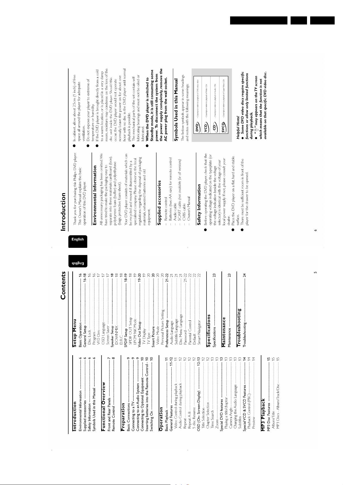
Contents Page
1 Technical Specs and Connection Facilities 2
2 Safety Instructions, Warnings, Notes 4
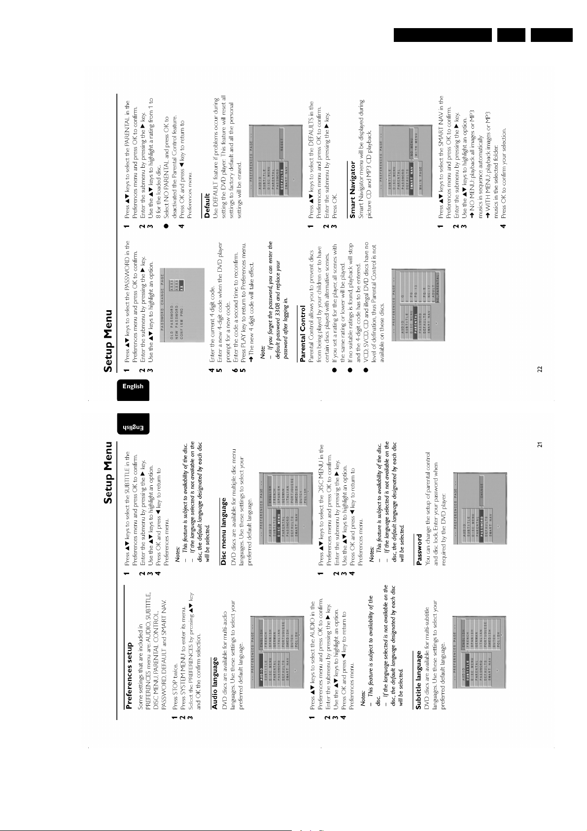
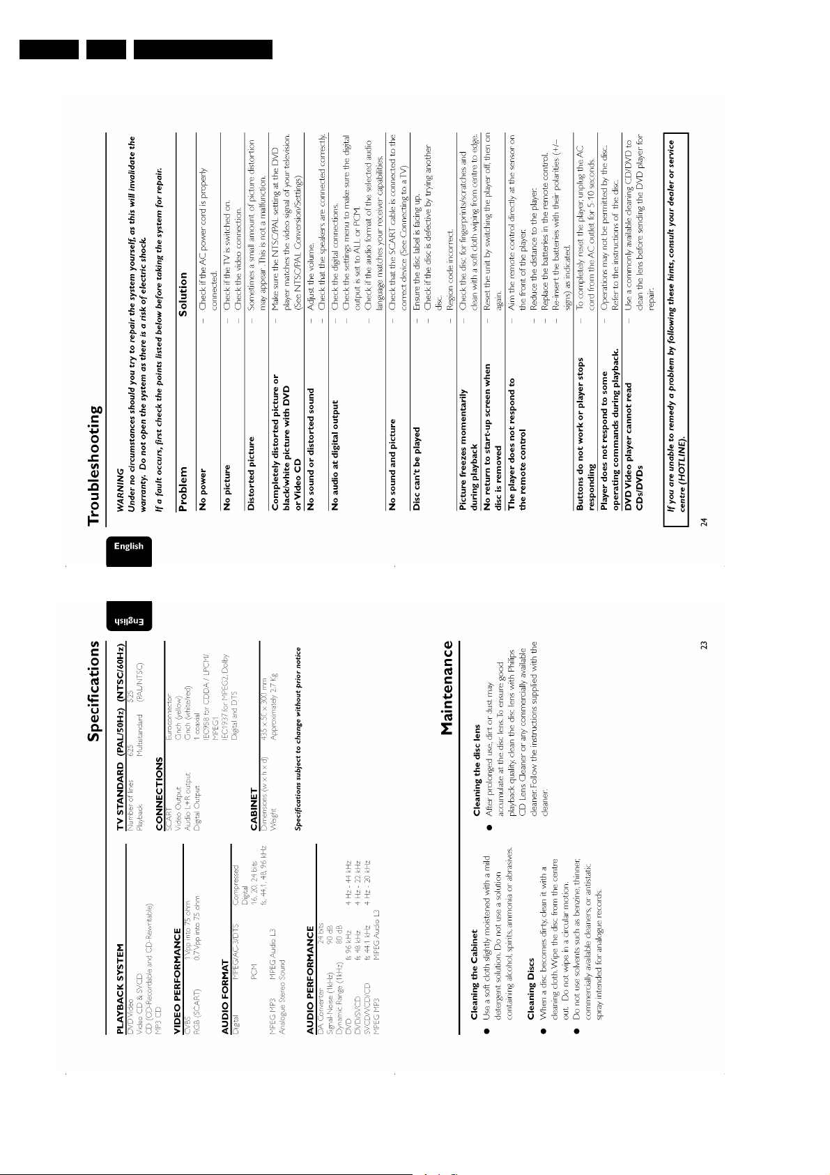
3 Directions for Use 5
4 Mechanical-, Dismantling Instructions, and Service
Hints 15
5 Diagnostic Software, Trouble Shooting and Test
Instructions 17
6 Block-, Wiring Diagram and Testpoint Overview
Block Diagram 25
Wiring Diagram 26
Testpoint Overview MPEG Board 27
7 Electrical Diagrams and Print-Layouts Diagram PWB
Power Supply Unit 28 29-30
MPEG Board: Processor (Diagram M1) 31 34-38
MPEG Board: Audio/Power (Diagram M2) 32 33-38
MPEG Board: Video & SCART (Diagram M3) 33 33-38
Front Board (Diagram D) 39 40
8 Alignments(Not Applicable) 41
9 Circuit Descriptions(Not Applicable) 41
List of Abbreviations(Not Applicable) 41
IC Data 41
10 Spare Parts List 44
11 Errata 47
©
Copyright 2002 Philips Consumer Electronics B.V. Eindhoven, The Netherlands.
All rights reserved. No part of this publication may be reproduced, stored in a
retrieval system or transmitted, in any form or by any means, electronic,
mechanical, photocopying, or otherwise without the prior permission of Philips.
Published by MW 0271 Service PaCE Printed in the Netherlands Subject to modification EN 3122 785 12801
EN 2 DVD733 /xx11.
s
Technical Specifications and PWB Location Drawing
1. Technical Specifications and PWB Location Drawing
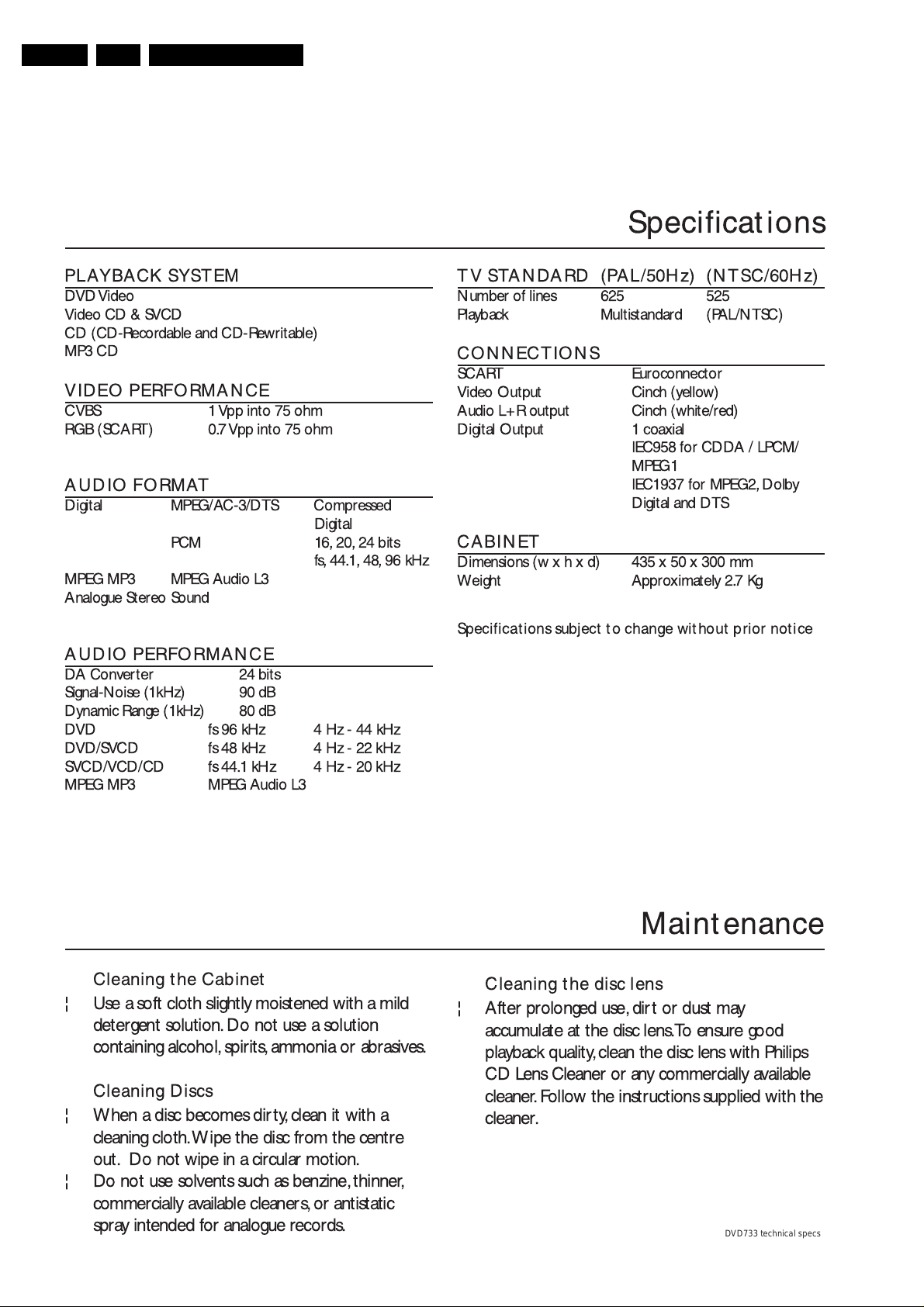
1.1 Technical Specifications
Specification
PLAYBACK SYSTEM
DVDVideo
Video CD & SVCD
CD (CD-Recordable and CD-Rewritable)
MP3 CD
VIDEO PERFORMANCE
CVBS 1 Vpp into 75 ohm
RGB (SCART) 0.7Vpp into 75 ohm
AUDIO FORMAT
Digital MPEG/AC-3/DTS Compressed
Digital
PCM 16, 20, 24 bits
fs, 44.1, 48, 96 kHz
MPEG MP3 MPEG Audio L3
Analogue Stereo Sound
AUDIO PERFORMANCE
DA Converter 24 bits
Signal-Noise (1kHz) 90 dB
Dynamic Range (1kHz) 80 dB
DVD fs96kHz 4Hz-44kHz
DVD/SVCD fs 48 kHz 4 Hz - 22 kHz
SVCD/VCD/CD fs 44.1 kHz 4 Hz - 20 kHz
MPEG MP3 MPEG Audio L3
TV STANDARD (PAL/50Hz) (NTSC/60Hz)
Number of lines 625 525
Playback Multistandard (PAL/NTSC)
CONNECTIONS
SCART Euroconnector
Video Output Cinch (yellow)
Audio L+R output Cinch (white/red)
Digital Output 1 coaxial
IEC958 for CDDA / LPCM/
MPEG1
IEC1937 for MPEG2, Dolby
Digital and DTS
CABINET
Dimensions (wxhxd) 435x50x300mm
Weight Approximately 2.7 Kg
Specifications subject to change without prior notice
Cleaning the Cabinet
¦
Use a soft cloth slightly moistened with a mild
detergent solution. Do not use a solution
containing alcohol, spirits, ammonia or abrasives.
Cleaning Discs
¦
When a disc becomes dirty, clean it with a
cleaning cloth.Wipe the disc from the centre
out. Do not wipe in a circular motion.
¦
Do not use solvents such as benzine, thinner,
commercially available cleaners, or antistatic
spray intended for analogue records.
Maintenance
Cleaning the disc lens
¦
After prolonged use, dirt or dust may
accumulate at the disc lens.To ensure good
playback quality, clean the disc lens with Philips
CD Lens Cleaner or any commercially available
cleaner. Follow the instructions supplied with the
cleaner.
DVD733 technical specs
Technical Specifications and PWB Location Drawing
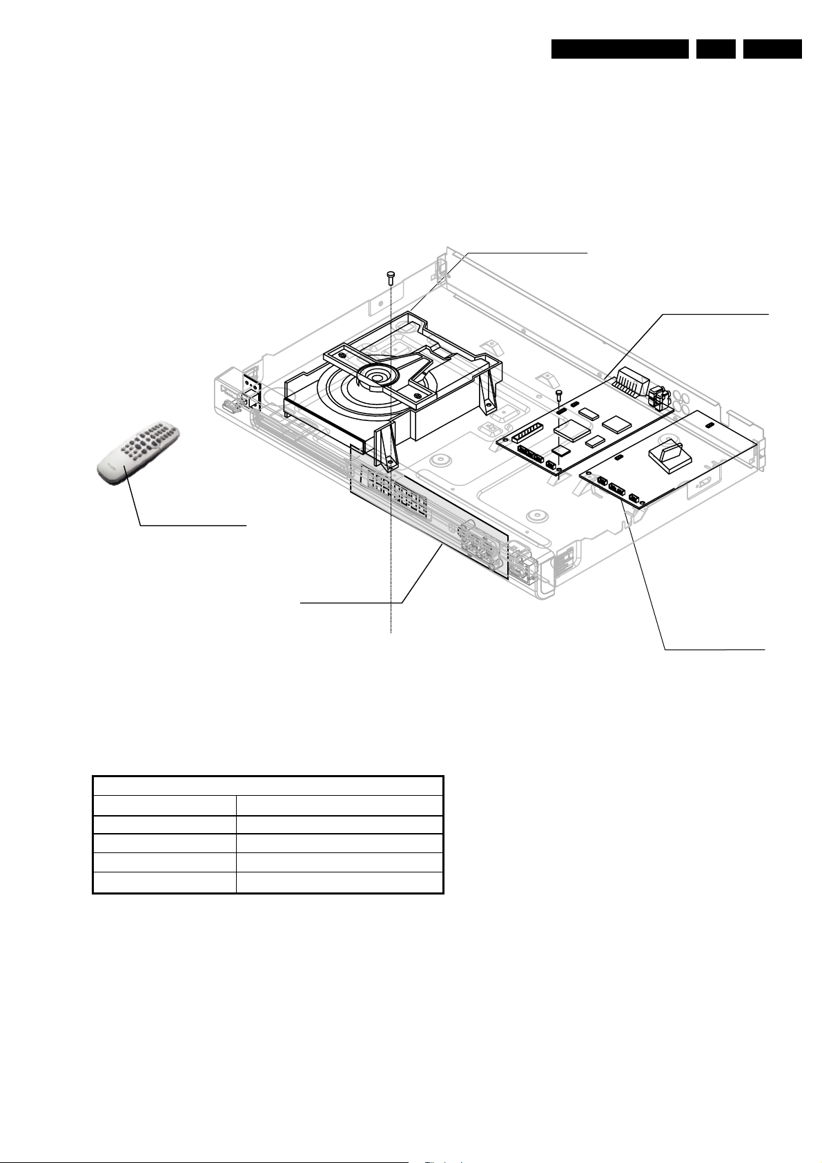
1.2 PWB Location Drawing
EN 3DVD733 /xx1 1.
PCB LOCATION DVD733/
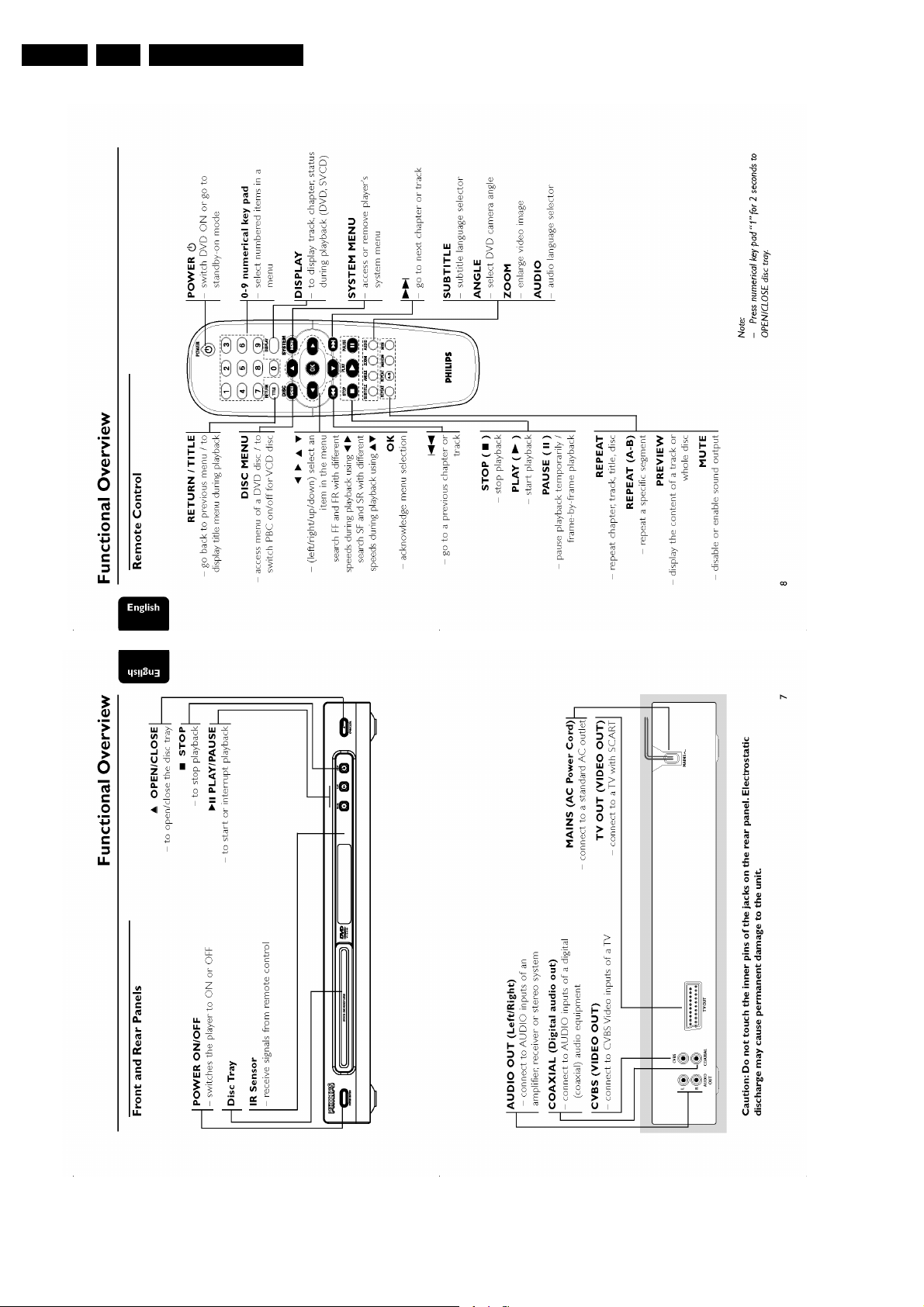
Remote Control
001/021/051
1003
Loader module
1002
MPEG
board
PARTS 12NC LIST
DVD733/001/021/051
1001 PSU board
1002 MPEG board
1003 Loader module
1004 Front board
Remote control
1004
Front board
1001
Power board
3122 427 23431
3139 248 82362
3141 018 03140
3141 018 03251
3141 017 90220
Figure 1-1 PWB Location Drawing
EN 4 DVD733 /xx12.
Safety Instructions, Warnings and Notes
2. Safety Instructions, Warnings and Notes
2.1 Safety Instructions
2.1.1 General Safety
Safety regulations require that during a repair:
• Connect the unit to the mains via an isolation transformer.
• Replace safety components, indicated by the symbol ,
only by components identical to the original ones. Any
other component substitution (other than original type) may
increase risk of fire or electrical shock hazard.
Safety regulations require that after a repair, you must return
the unit in its original condition. Pay, in particular, attention to
the following points:
• Route the wires/cables correctly, and fix them with the
mounted cable clamps.
• Check the insulation of the mains lead for external
damage.
• Check the electrical DC resistance between the mains plug
and the secondary side:
1. Unplug the mains cord, and connect a wire between
the two pins of the mains plug.
2. Set the mains switch to the 'on' position (keep the
mains cord unplugged!).
3. Measure the resistance value between the mains plug
and the front panel, controls, and chassis bottom.
4. Repair or correct unit when the resistance
measurement is less than 1 MΩ.
5. Verify this, before you return the unit to the customer/
user (ref. UL-standard no. 1492).
6. Switch the unit ‘off’, and remove the wire between the
two pins of the mains plug.
2.1.2 Laser Safety
This unit employs a laser. Only qualified service personnel may
remove the cover, or attempt to service this device (due to
possible eye injury).
2.2 Warnings
2.2.1 General
• All ICs and many other semiconductors are susceptible to
electrostatic discharges (ESD, symbol ). Careless
handling during repair can reduce life drastically. Make
sure that, during repair, you are at the same potential as
the mass of the set by a wristband with resistance. Keep
components and tools at this same potential. Available
ESD protection equipment:
– Complete kit ESD3 (small tablemat, wristband,
connection box, extension cable and earth cable) 4822
310 10671.
– Wristband tester 4822 344 13999.
• Be careful during measurements in the live voltage section.
The primary side of the power supply (pos. 1005), including
the heatsink, carries live mains voltage when you connect
the player to the mains (even when the player is 'off'!). It is
possible to touch copper tracks and/or components in this
unshielded primary area, when you service the player.
Service personnel must take precautions to prevent
touching this area or components in this area. A 'lightning
stroke' and a stripe-marked printing on the printed wiring
board, indicate the primary side of the power supply.
• Never replace modules, or components, while the unit is
‘on’.
2.2.2 Laser
• The use of optical instruments with this product, will
increase eye hazard.
• Only qualified service personnel may remove the cover or
attempt to service this device, due to possible eye injury.
• Repair handling should take place as much as possible
with a disc loaded inside the player.
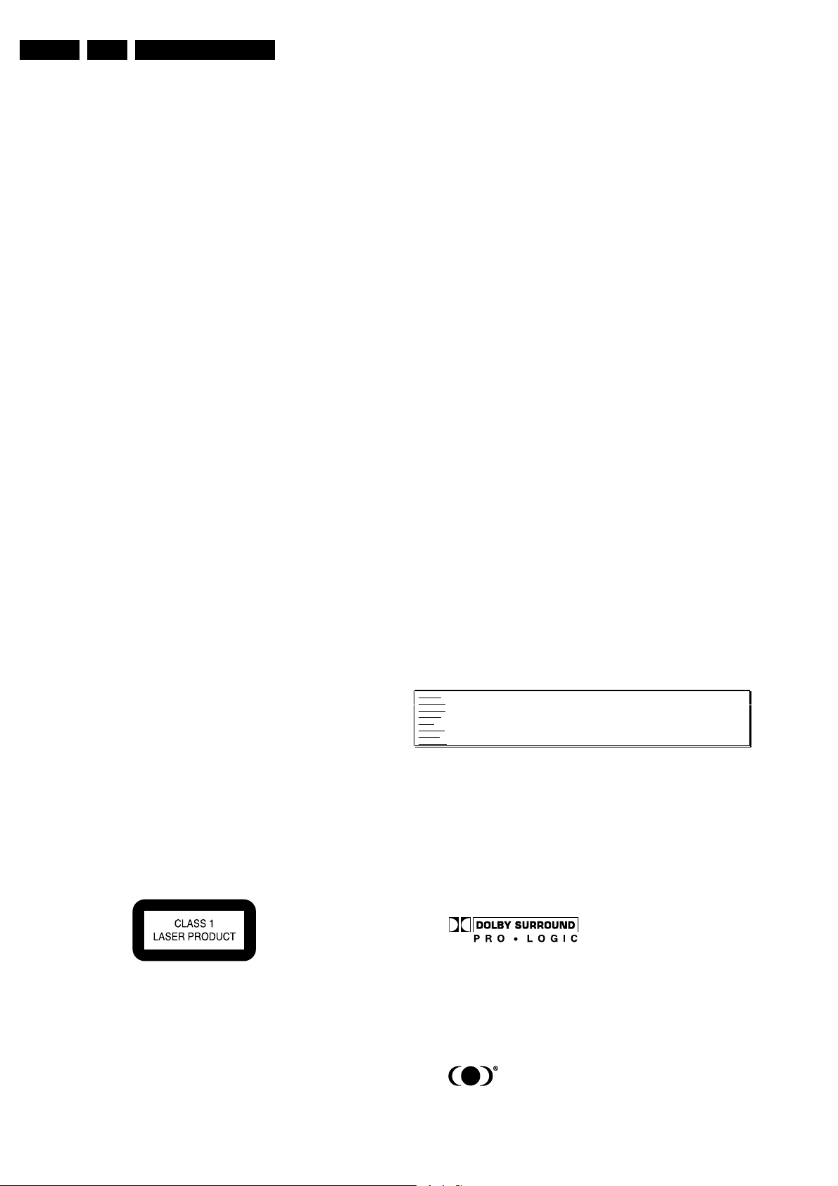
• Text below is placed inside the unit, on the laser cover
shield:
Laser Device Unit
Type : Semiconductor laser
GaAlAs
Wavelength : 650 nm (DVD)
: 780 nm (VCD/CD)
Output Power : 20 mW (DVD+RW
writing)
: 0.8 mW (DVD
reading)
: 0.3 mW (VCD/CD
reading)
Beam divergence : 60 degree
Figure 2-1 Class 1 Laser Product
Note: Use of controls or adjustments or performance of
procedure other than those specified herein, may result in
hazardous radiation exposure. Avoid direct exposure to beam.
CAUTION VISIBLE AND INVISIBLE LASER RADIATION WHEN OPEN AVOID EXPOSURE TO BEAM
ADVARSEL SYNLIG OG USYNLIG LASERSTRÅLING VED ÅBNING UNDGÅ UDSÆTTELSE FOR STRÅLING
ADVARSEL SYNLIG OG USYNLIG LASERSTRÅLING NÅR DEKSEL ÅPNES UNNGÅ EKSPONERING FOR STRÅLEN
VARNING SYNLIG OCH OSYNLIG LASERSTRÅLNING NÄR DENNA DEL ÄR ÖPPNAD BETRAKTA EJ STRÅLEN
VARO! AVATTAESSA OLET ALTTIINA NÄKYVÄLLE JA NÄKYMÄTTÖMÄLLE LASER SÄTEILYLLE. ÄLÄ KATSO SÄTEESEEN
VORSICHT SICHTBARE UND UNSICHTBARE LASERSTRAHLUNG WENN ABDECKUNG GEÖFFNET NICHT DEM STRAHL AUSSETSEN
DANGER VISIBLE AND INVISIBLE LASER RADIATION WHEN OPEN AVOID DIRECT EXPOSURE TO BEAM
ATTENTION RAYONNEMENT LASER VISIBLE ET INVISIBLE EN CAS D'OUVERTURE EXPOSITION DANGEREUSE AU FAISCEAU
!
Figure 2-2 Warning text
2.2.3 Notes
Dolby
Manufactered under licence from Dolby Laboratories. “Dolby”,
“Pro Logic” and the double-D symbol are trademarks of Dolby
Laboratories. Confidential Unpublished Works. ©1992-1997
Dolby Laboratories, Inc. All rights reserved.
Figure 2-3
Trusurround
TRUSURROUND, SRS and symbol (fig 2-4) are trademarks of
SRS Labs, Inc. TRUSURROUND technology is manufactured
under licence frm SRS labs, Inc.
Figure 2-4
3. Directions for Use
Directions for Use
EN 5DVD733 /xx1 3.
EN 6 DVD733 /xx13.
Directions for Use
Directions for Use
EN 7DVD733 /xx1 3.

EN 8 DVD733 /xx13.
Directions for Use

Directions for Use
EN 9DVD733 /xx1 3.

EN 10 DVD733 /xx13.
Directions for Use
Directions for Use
EN 11DVD733 /xx1 3.

EN 12 DVD733 /xx13.
Directions for Use
Directions for Use
EN 13DVD733 /xx1 3.
EN 14 DVD733 /xx13.
Directions for Use

Mechanical- and Dismantling Instructions
4. Mechanical- and Dismantling Instructions
Dismantling Instructions
(PSUboardtoframe)
Removescrews
Releasesnapof1spacer
Removeflexconnectionsto
PSUboard1001
PSUboard
locking(boardtoframe)Demountboard
EN 15DVD733 /xx1 4.
DVD733dismatling.eps
Mounting
Removescrews
Cover232
Demounting
Liftcoveratrearsidetoremove
Removeflexconnectionsto
MPEGboard1002
Removeconnectionsto
Loadermodule1003
MPEGboard
MPEGandPSUboard
Removescrews
Removescrews
(MPEGboardtobackplate)
(loadertobracket)
Removescrews
Demountloadermodule
(MPEGboardtoframe)
Demountboard
DISMANTLINGINSTRUCTIONSDVD733/001/021/051
Seeexplodedviewforitemnumbers
Frontassy200
Unlockfrontfromframeby
releasingsuccessivelysnaps
Placefrontassyinfrontof
theset(serviceposition)
Removescrews
Switchassy
Removevolumeknob
Displayboard1004
Demountswitchassy
(boardtofront)
Removescrews
Demountboard
bypullingitforward
 Loading...