

Philips DVD-723 Service manual
DVD-Video Player DVD723-743
DVD723 /001 /021 /051
DVD743 /001 /021 /051
Contents Page
1 Technical Specs and Connection Facilities 2
2 Safety Instructions, Warnings, Notes,
and Service Hints 4
3 Directions for Use 6
4 Mechanical- and Dismantling Instructions 19
5 Diagnostic Software, Trouble Shooting and Test
Instructions 22
6 Wiring-, Block Diagrams
Block Diagram 41
Wiring Diagram 42/43
7 Electrical Diagrams and Print-Layouts Diagram PWB
Power Supply Unit 44 45
AV Board: Video & SCART (Diagram A1) 46 49-52
AV Board: Audio (Diagram A2) 47 49-52
AV Board: Regulated Supply (Diagram A3) 48 49-52
Testpoint Overview 53
Front DVD723: Display (Diagram D) 54 55-57
Front DVD723: Standby (Diagram S) 58 58
Front DVD743: Display (Diagram D) 59 60-62
Front DVD743: Standby (Diagram S) 63 63
Switching 64
SCART 65 66-68
8 Alignments (Not Applicable) 69
9 Circuit Descriptions, List of Abbreviations,
and IC Data 69
10 Spare Parts List 74
©
Copyright 2002 Philips Consumer Electronics B.V. Eindhoven, The Netherlands.
All rights reserved. No part of this publication may be reproduced, stored in a
retrieval system or transmitted, in any form or by any means, electronic,
mechanical, photocopying, or otherwise without the prior permission of Philips.
Published by MW 0263 Service PaCE Printed in the Netherlands Subject to modification EN 3122 785 12240

EN 2 DVD 723-7431.
Technical Specifications and Connection Facilities
1. Technical Specifications and Connection Facilities
1.1 DVD723/0X1
PLAYBACK SYSTEM
DVD Video
Video CD & SVCD
CD (CD-Recordable and CD-Rewritable)
MP3 CD
TV STANDARD (PAL/50Hz) (NTSC/60Hz)
Number of lines 625 525
Playback Multistandard (PAL/NTSC)
VIDEO PERFORMANCE
Video output 1 Vpp into 75 ohm
RGB (SCART) output 0.7 Vpp into 75 ohm
Black Level Shift On/Off
Video Shift Left/Right
AUDIO FORMAT
Digital MPEG Compressed
Digital
Dolby Digital 16, 20, 24 bits
PCM fs, 44.1, 48, 96 kHz
MPEG MP3 MPEG Audio L3
Analogue Stereo Sound
Dolby Surround-compatible downmix from Dolby Digital
multi-channel sound
3D Sound for virtual 5.1 channel sound on 2 speakers
AUDIO PERFORMANCE
DA Converter 24 bits
DVD fs 96 kHz 4 Hz - 44 kHz
DVD/SVCD fs 48 kHz 4 Hz - 22 kHz
SVCD/VCD/CD fs 44.1 kHz 4 Hz - 20 kHz
Signal-Noise (1kHz) > 105 dB
Dynamic Range (1kHz) > 100 dB
Crosstalk (1kHz) > 105 dB
Distortion and Noise (1kHz) > 90 dB
MPEG MP3 MPEG Audio L3
CONNECTIONS
SCART Euroconnector
S-Video Output Mini DIN, 4 pins
Video Output Cinch (yellow)
Audio L+R output Cinch (white/red)
Audio Subwoofer Cinch (black)
Digital Output 1 coaxial, 1 optical
IEC958 for CDDA / LPCM
IEC1937 for MPEG1/2, Dolby
Digital
CABINET
Dimensions (w x h x d) 435 x 75 x 302 mm
Weight Approximately 2.8 Kg
* typical playing time for movie with 2 spoken languages and
3 subtitle languages
Specifications subject to change without prior notice

1.2 DVD743/0X1
PLAYBACK SYSTEM
DVD Video
Video CD & SVCD
CD (CD-Recordable and CD-Rewritable)
MP3 CD
TV STANDARD (PAL/50Hz) (NTSC/60Hz)
Number of lines 625 525
Playback Multistandard (PAL/NTSC)
VIDEO PERFORMANCE
Video output 1 Vpp into 75 ohm
RGB (SCART) output 0.7 Vpp into 75 ohm
Black Level Shift On/Off
Video Shift Left/Right
AUDIO FORMAT
Digital MPEG Compressed
Digital
Dolby Digital 16, 20, 24 bits
PCM fs, 44.1, 48, 96 kHz
MPEG MP3 MPEG Audio L3
Analogue Stereo Sound
Dolby Surround-compatible downmix from Dolby Digital
multi-channel sound
3D Sound for virtual 5.1 channel sound on 2 speakers
AUDIO PERFORMANCE
DA Converter 24 bits
DVD fs 96 kHz 4 Hz - 44 kHz
DVD/SVCD fs 48 kHz 4 Hz - 22 kHz
SVCD/VCD/CD fs 44.1 kHz 4 Hz - 20 kHz
Signal-Noise (1kHz) > 110 dB
Dynamic Range (1kHz) > 100 dB
Crosstalk (1kHz) > 105 dB
Distortion and Noise (1kHz) > 90 dB
MPEG MP3 MPEG Audio L3
CONNECTIONS
SCART 2x Euroconnector
S-Video Output Mini DIN, 4 pins
Video Output Cinch (yellow)
Audio L+R output 2x Cinch (white/red)
Audio Subwoofer Cinch (black)
Digital Output 1 coaxial, 1 optical
IEC958 for CDDA / LPCM
IEC1937 for MPEG1/2, Dolby
Digital
CABINET
Dimensions (w x h x d) 435 x 77.5 x 303.5 mm
Weight Approximately 2.8 Kg
* typical playing time for movie with 2 spoken languages and
3 subtitle languages
Specifications subject to change without prior notice
Technical Specifications and Connection Facilities
EN 3DVD 723-743 1.
EN 4 DVD 723-7432.
Safety Instructions, Warnings, Notes, and Service Hints
2. Safety Instructions, Warnings, Notes, and Service Hints
2.1 Safety Instructions
2.1.1 General Safety
Safety regulations require that during a repair:
• Connect the unit to the mains via an isolation transformer.
• Replace safety components, indicated by the symbol ,
only by components identical to the original ones. Any
other component substitution (other than original type) may
increase risk of fire or electrical shock hazard.
Safety regulations require that after a repair, you must return
the unit in its original condition. Pay, in particular, attention to
the following points:
• Route the wires/cables correctly, and fix them with the
mounted cable clamps.
• Check the insulation of the mains lead for external
damage.
• Check the electrical DC resistance between the mains plug
and the secondary side:
1. Unplug the mains cord, and connect a wire between
the two pins of the mains plug.
2. Set the mains switch to the 'on' position (keep the
mains cord unplugged!).
3. Measure the resistance value between the mains plug
and the front panel, controls, and chassis bottom.
4. Repair or correct unit when the resistance
measurement is less than 1 MΩ.
5. Verify this, before you return the unit to the customer/
user (ref. UL-standard no. 1492).
6. Switch the unit ‘off’, and remove the wire between the
two pins of the mains plug.
2.1.2 Laser Safety
This unit employs a laser. Only qualified service personnel may
remove the cover, or attempt to service this device (due to
possible eye injury).
2.2 Warnings
2.2.1 General
• All ICs and many other semiconductors are susceptible to
electrostatic discharges (ESD, "). Careless handling
during repair can reduce life drastically. Make sure that,
during repair, you are at the same potential as the mass of
the set by a wristband with resistance. Keep components
and tools at this same potential.
Available ESD protection equipment:
– Complete kit ESD3 (small tablemat, wristband,
connection box, extension cable and earth cable) 4822
310 10671.
– Wristband tester 4822 344 13999.
• Be careful during measurements in the live voltage section.
The primary side of the power supply (pos. 1005), including
the heatsink, carries live mains voltage when you connect
the player to the mains (even when the player is 'off'!). It is
possible to touch copper tracks and/or components in this
unshielded primary area, when you service the player.
Service personnel must take precautions to prevent
touching this area or components in this area. A 'lightning
stroke' and a stripe-marked printing on the printed wiring
board, indicate the primary side of the power supply.
• Never replace modules, or components, while the unit is
‘on’.
2.2.2 Laser
• The use of optical instruments with this product, will
increase eye hazard.
• Only qualified service personnel may remove the cover or
attempt to service this device, due to possible eye injury.
• Repair handling should take place as much as possible
with a disc loaded inside the player.
• Text below is placed inside the unit, on the laser cover
shield:
Laser Device Unit
Type : Semiconductor laser
GaAlAs
Wavelength : 650 nm (DVD)
: 780 nm (VCD/CD)
Output Power : 20 mW
(DVD+RW writing)
:0.8 mW
(DVD reading)
:0.3 mW
(VCD/CD reading)
Beam divergence : 60 degree
Figure 2-1
Note: Use of controls or adjustments or performance of
procedure other than those specified herein, may result in
hazardous radiation exposure. Avoid direct exposure to beam.
CAUTION VISIBLE AND INVISIBLE LASER RADIATION WHEN OPEN AVOID EXPOSURE TO BEAM
ADVARSEL SYNLIG OG USYNLIG LASERSTRÅLING VED ÅBNING UNDGÅ UDSÆTTELSE FOR STRÅLING
ADVARSEL SYNLIG OG USYNLIG LASERSTRÅLING NÅR DEKSEL ÅPNES UNNGÅ EKSPONERING FOR STRÅLEN
VARNING SYNLIG OCH OSYNLIG LASERSTRÅLNING NÄR DENNA DEL ÄR ÖPPNAD BETRAKTA EJ STRÅLEN
VARO! AVATT AESSA OLET ALTTIINA NÄKYVÄLLE JA NÄKYMÄTTÖMÄLLE LASER SÄTEILYLLE. ÄLÄ KATSO SÄTEESEEN
VORSICHT SICHTBARE UND UNSICHTBARE LASERSTRAHLUNG WENN ABDECKUNG GEÖFFNET NICHT DEM STRAHL AUSSETSEN
DANGER VISIBLE AND INVISIBLE LASER RADIATION WHEN OPEN AVOID DIRECT EXPOSURE TO BEAM
ATTENTION RAYO NNEMENT LASER VISIBLE ET INVISIBLE EN CAS D'OUVERTURE EXPOSITION DANGEREUSE AU FAISCEAU
!
Figure 2-2
2.2.3 Notes
Dolby
Manufactered under licence from Dolby Laboratories. “Dolby”,
“Pro Logic” and the double-D symbol are trademarks of Dolby
Laboratories. Confidential Unpublished Works.
©1992-1997 Dolby Laboratories, Inc. All rights reserved.
Figure 2-3
Trusurround
TRUSURROUND, SRS and symbol (fig 2-4) are trademarks of
SRS Labs, Inc. TRUSURROUND technology is manufactured
under licence frm SRS labs, Inc.
Figure 2-4
Safety Instructions, Warnings, Notes, and Service Hints
EN 5DVD 723-743 2.
2.3 Service Hints
2.3.1 Switched Mode Power Supply
The power supply unit has to be replaced in case of failure. The
schematic provided in the manual is only for information and no
service parts will be available.
2.3.2 DVD Module
This module can be repaired as follows:
1. The VAL6013/01 is a combination of loading mechanism
and DVD-mechanism. Both are not repairable units and in
case of failure, it has to be replaced with a new loader
VAL6013/01.
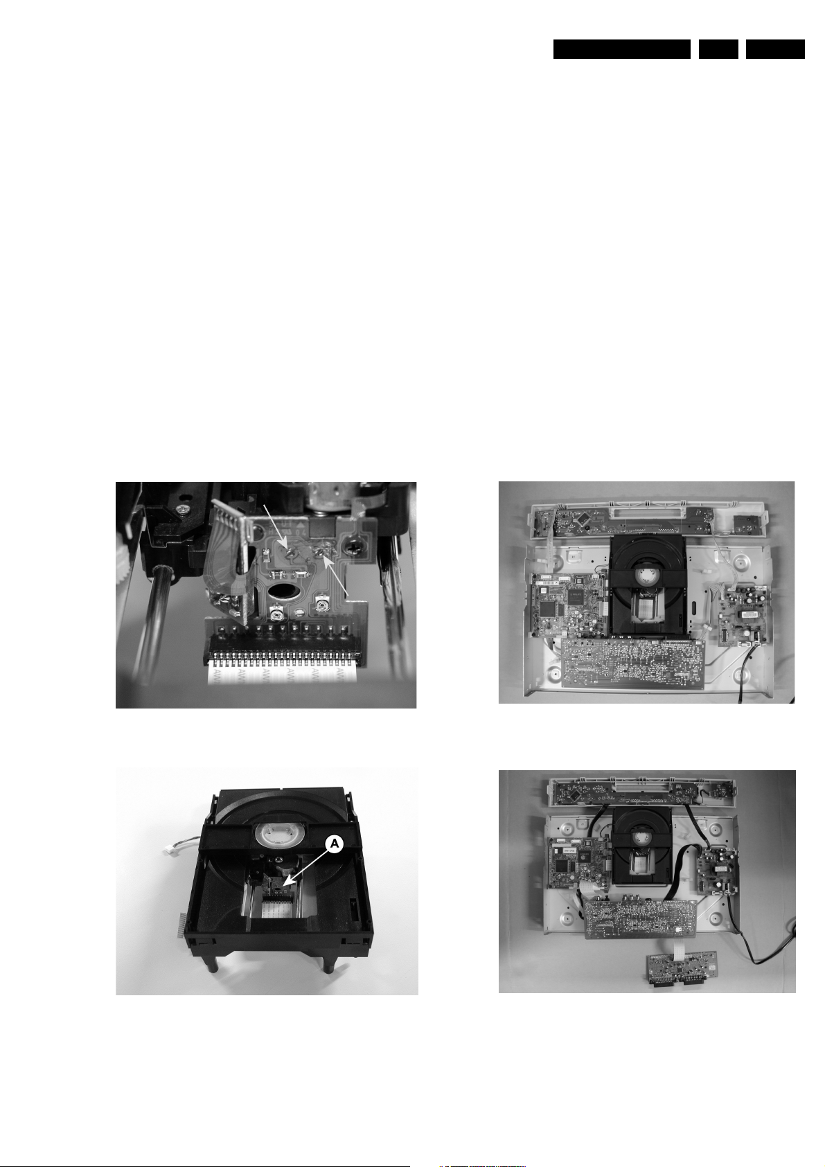
Note: When replacing with a new VAL6013/01, two solder
joints have to be removed after connecting the OPU flex foil
to the mono board.
The solder joints, which shortcircuits the laser diodes to
ground, are for protection against ESD. Refer to figures 25 and 2-6 for location of solder joints.
2. The mono board has to be repaired down to component
level. Repair handling of the monoboard requires a
workshop with sophisticated desoldering tools.
VAL6013/01 Solder Joints
2.3.3 ComPair
For assistance with the repair process of the monoboard an
electronic fault finding guidance has been developed. This
program is called ComPair.
This ComPair program is available on CDROM.
The version of the CDROM for repair of the monoboard is V1.3
or higher and can be ordered with codenumber 4822 727
21637. This is an update CDROM, so when the ComPair
CDROM is used for the first time, one has to install the ComPair
Engine CDROM V1.2 first.
The V1.2 CDROM can be ordered with code number 4822 727
21634 and has to registered after instalation. The procedure for
registration is explained in the help file of the program and in
the CDROM booklet.
The cable to connect the monoboard with a PC can be ordered
with codenumber: 3122 785 90017.
All the hardware and software requirements of the systems,
necessary for working with ComPair, are described on the
CDROM.
2.3.4 Service Positions
Refer to dismantling instructions for dismounting of the board.
Figures 2-7 to 2-8 shows the service position that are
recommended during repair of the boards.
DVD723/0X1 model
Figure 2-5
VAL6013/01 Solder Joints
Figure 2-6
Figure 2-7
DVD743/0X1 model
Figure 2-8
EN 6 DVD 723-7433.
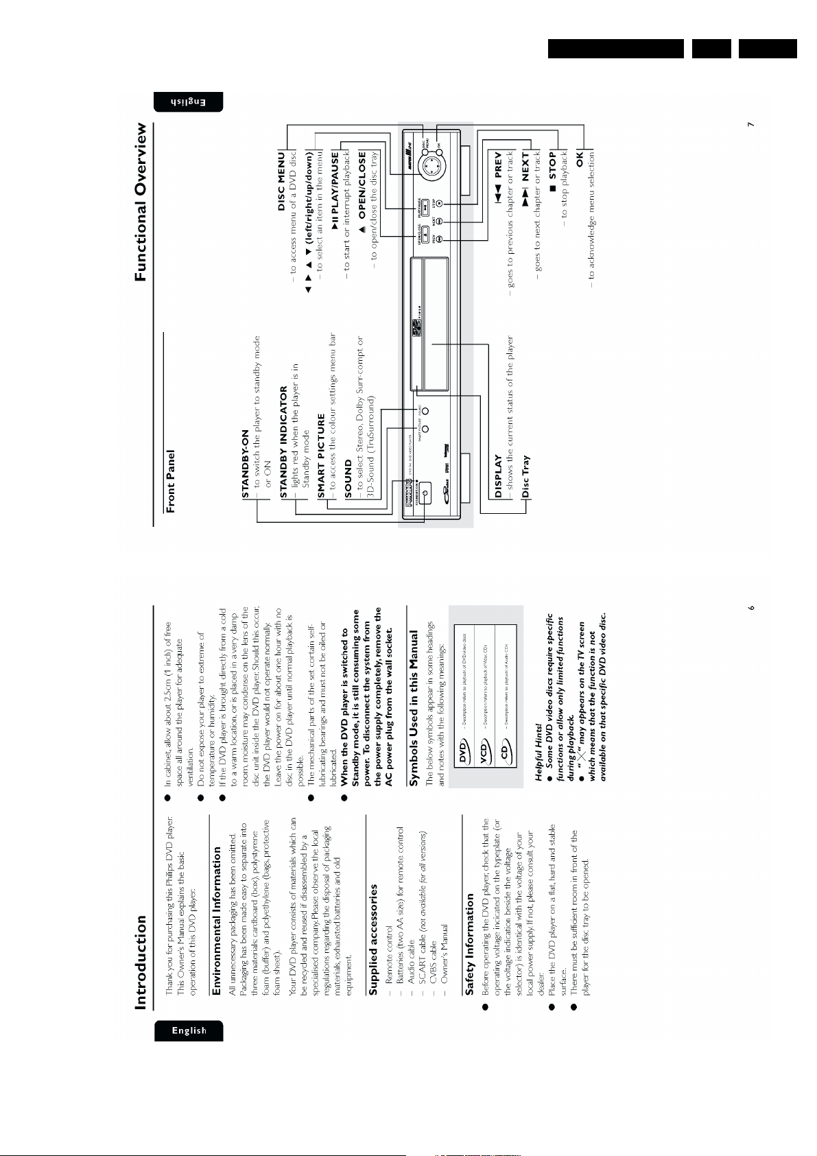
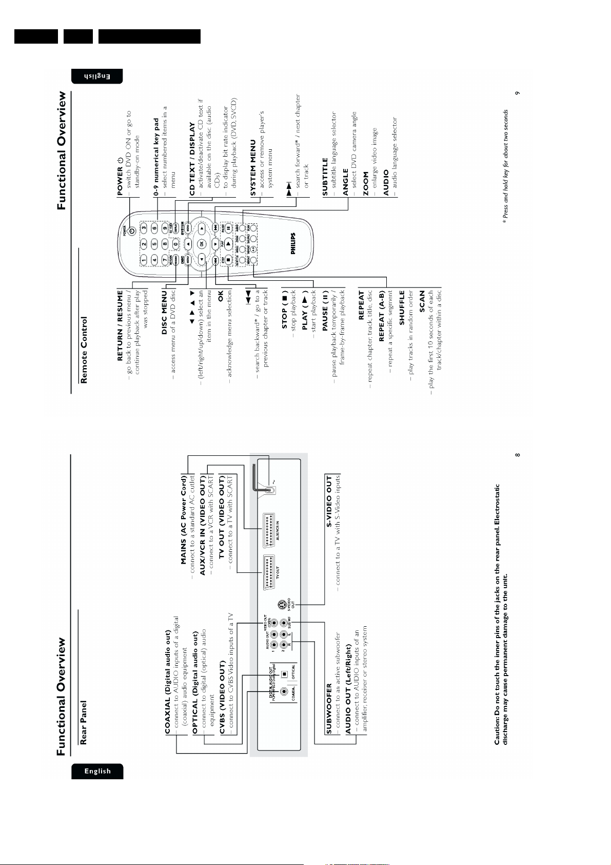
3. Directions for Use
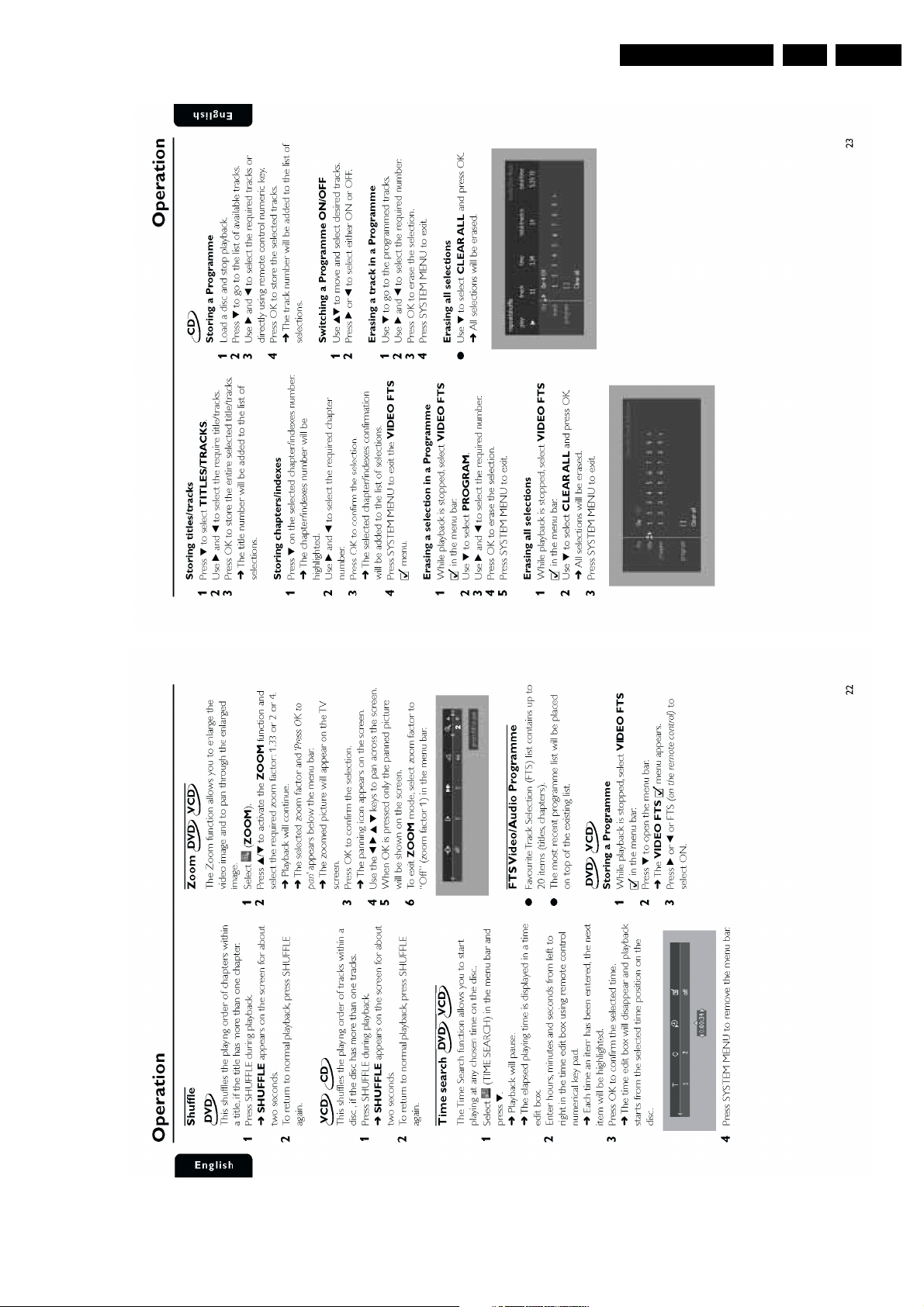
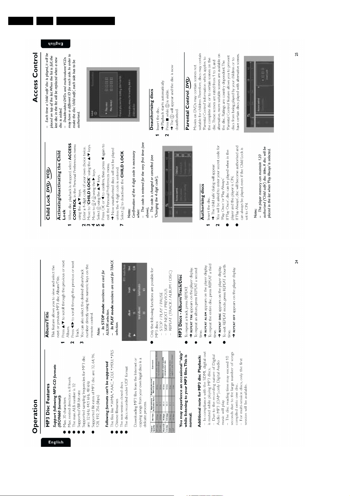
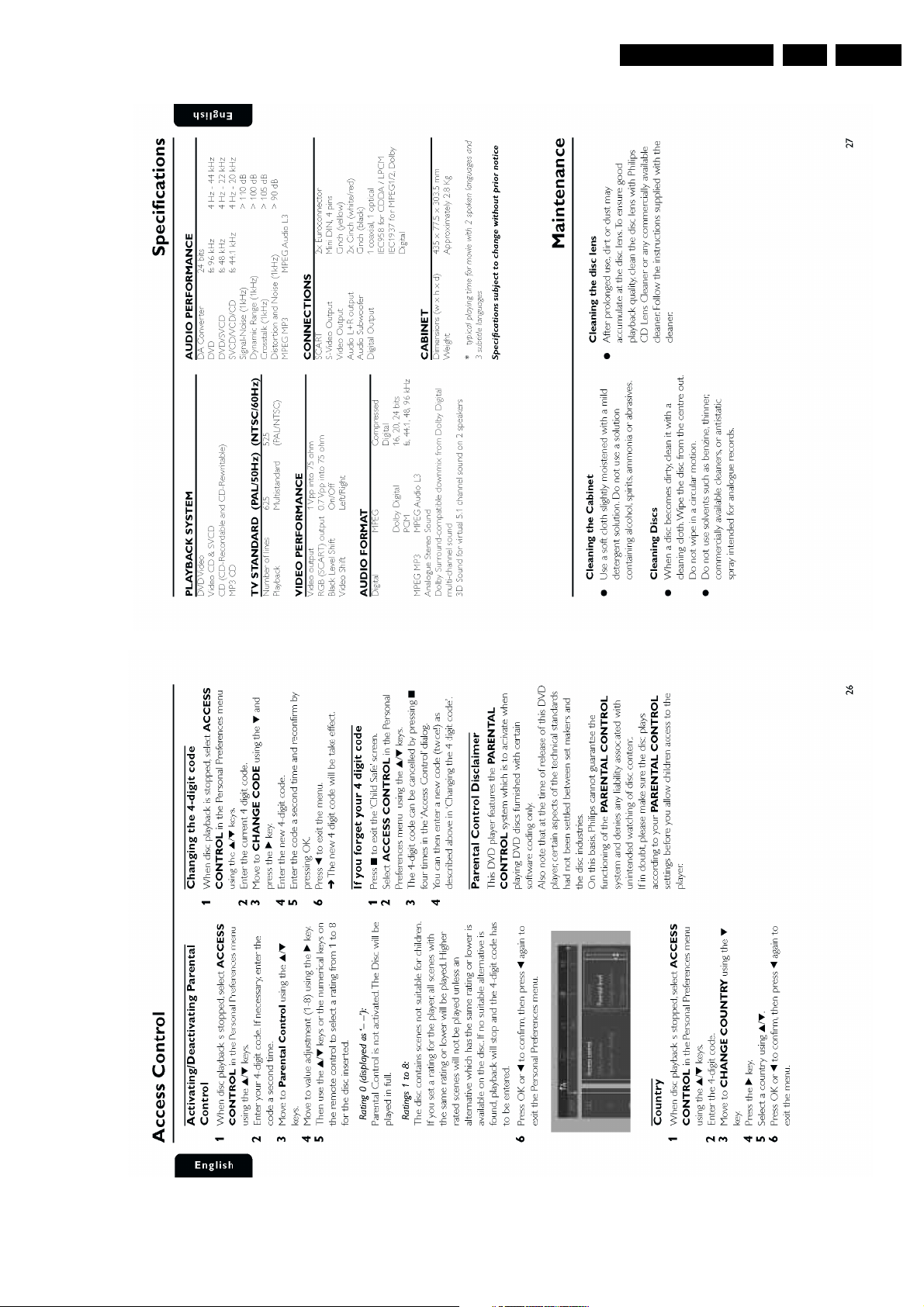
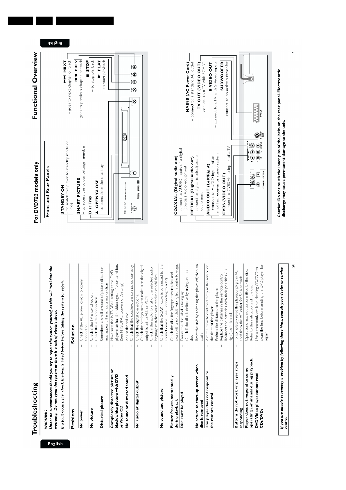
Directions for Use
Directions for Use
EN 7DVD 723-743 3.
EN 8 DVD 723-7433.
Directions for Use
Directions for Use
EN 9DVD 723-743 3.
EN 10 DVD 723-7433.
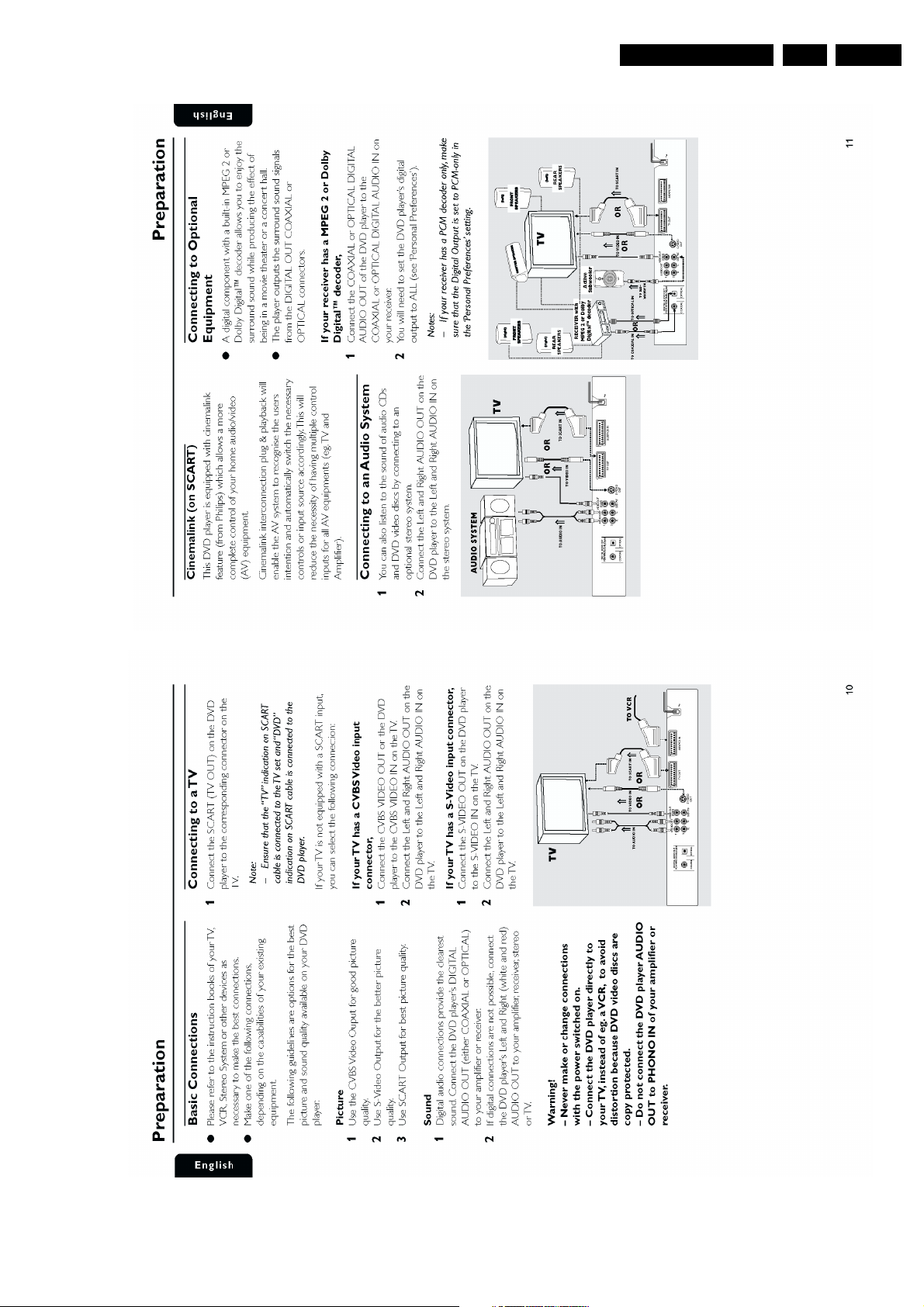
Directions for Use
Directions for Use
EN 11DVD 723-743 3.
EN 12 DVD 723-7433.
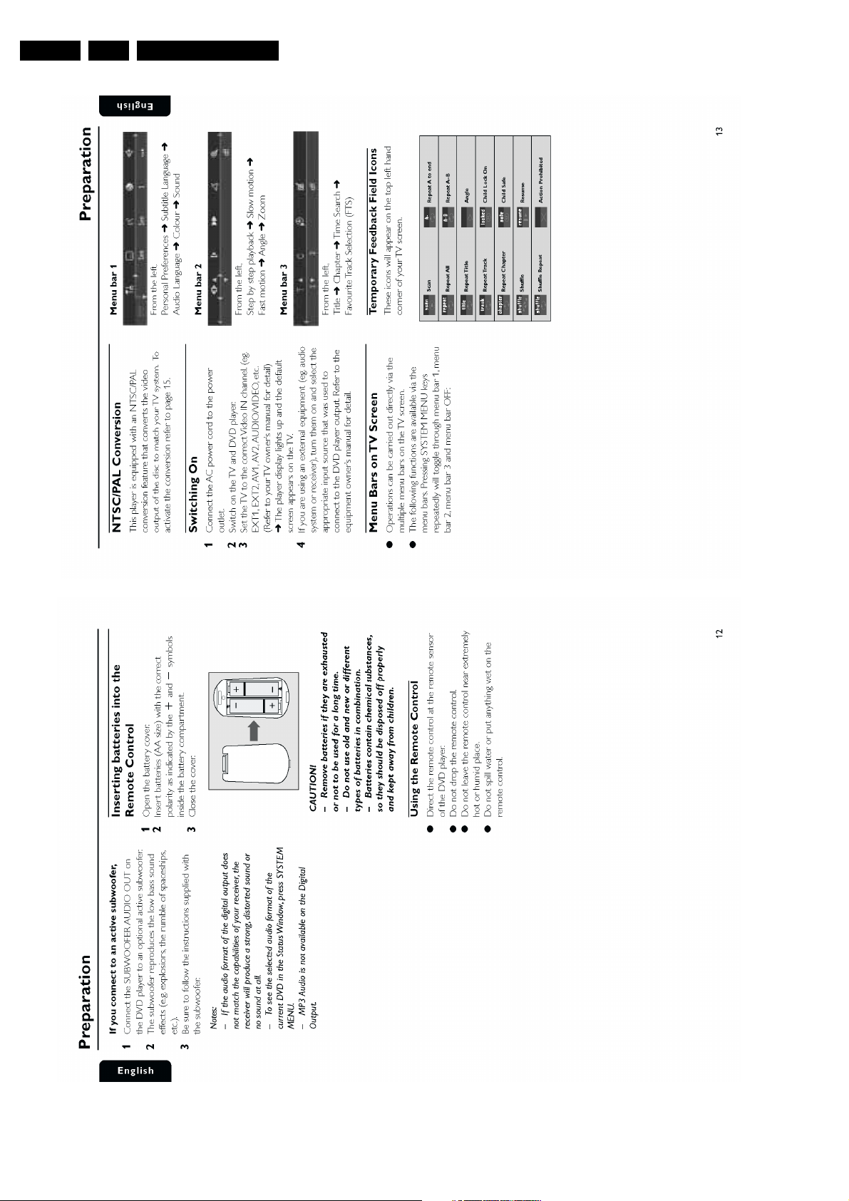
Directions for Use
Directions for Use
EN 13DVD 723-743 3.
EN 14 DVD 723-7433.
Directions for Use
Directions for Use
EN 15DVD 723-743 3.
EN 16 DVD 723-7433.
Directions for Use
Directions for Use
EN 17DVD 723-743 3.
EN 18 DVD 723-7433.
Directions for Use
Mechanical- and Dismantling Instructions
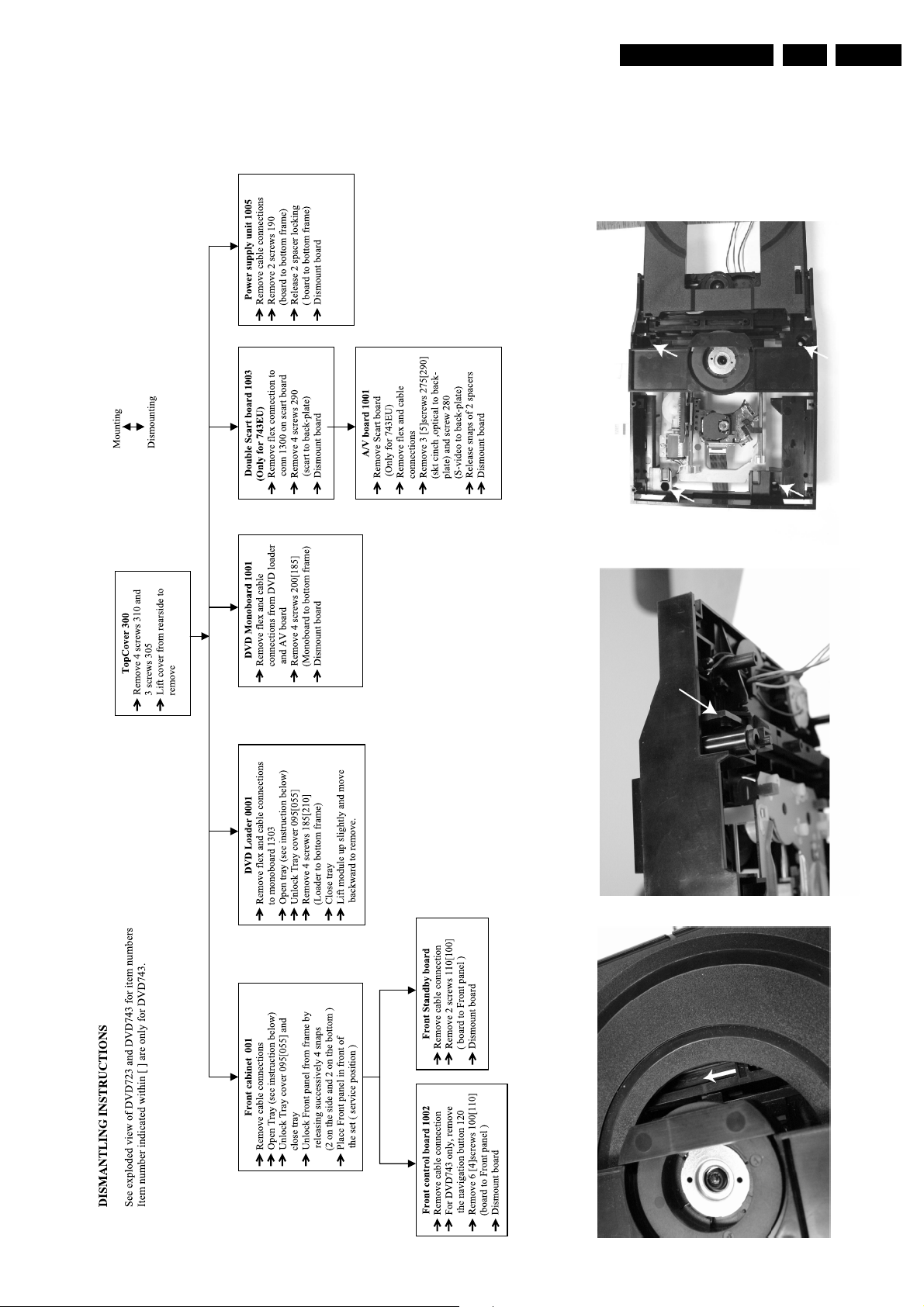
4. Mechanical- and Dismantling Instructions
Dismantling Instructions
EN 19DVD 723-743 4.
260302
Remove 4 screws to remove loader.
CL 26532039-015.eps
When a disc is loaded, unlock the tray by pushing the slide inwards with
a screwdriver and pull tray outwards.
When it is not possible to open the tray with the EJECT button,
the tray can manually be opened.
When no disc is loaded, unlock the tray by moving the slide from left
Manually opening of tray
to right and pull tray outwards.
EN 20 DVD 723-7434.
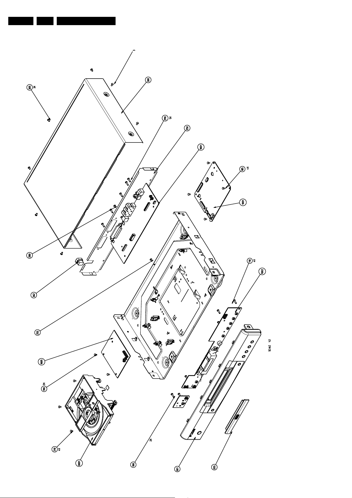
Exploded View DVD723/0X1
Mechanical- and Dismantling Instructions
260302
CL 26532039_010.eps
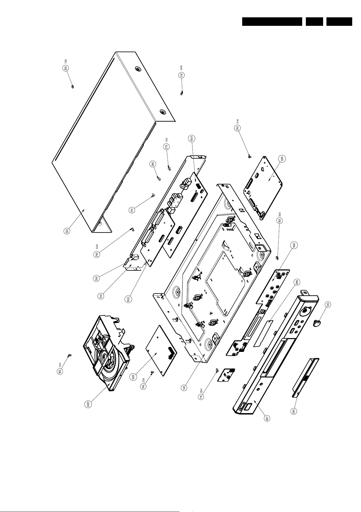
Exploded View DVD743/0X1
Mechanical- and Dismantling Instructions
EN 21DVD 723-743 4.
260302
CL 26532039_011.eps
EN 22 DVD 723-7435.
Diagnostic Software, Trouble Shooting and Test Instructions
5. Diagnostic Software, Trouble Shooting and Test Instructions
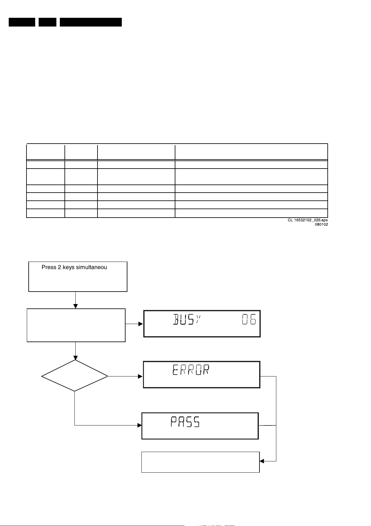
5.1 Dealerscript
5.1.1 Purpose of Dealer Script
The dealer script can give a diagnosis on a standalone DVD
player, no other equipment is needed to perform a number of
hardware tests to check if the DVD player is faulty. The
diagnosis is simply a "error" or "pass" message. No indication
is given of faulty hardware modules. Only tests within the scope
of the diagnostic software will be executed hence only faults
within this scope can be detected.
Nucleus
Display Nucleus Nucleus Description
Countdown Number Name
6 6 PapChksFl Calculate and verify checksum of FLASH memory
5 12 PapI2cDisp
4 13 PapS2bEcho Checks the I2C interface to the basic engine
3 11 PapI2cNvram Checks the I2C interface with the NVRAM
2 15 PapNvramWrR Pattern test of all locations in the NVRAM
1 16 CompSdramWrR Pattern test of all locations in the SDRAM(s)
5.1.2 Contents of Dealer Script
The dealer script executes all diagnostic nuclei that do not
need any user interaction and are meaningful on a standalone
DVD player.
The nuclei called in the dealer script are the following (the
number after each nucleus name corresponds with the number
being on the local display when the nucleus is executed during
the dealer script):
Checks the I2C interface with the slave processor on
the display board
CL 16532162_026.eps
Figure 5-1
080102
Dealer Script
Press 2 keys simultaneously
<OPEN/CLOSE> + <PLAY>
Connect to mains.
During the test, the following display
is shown: the counter counts down
from the number of nuclei to be run
before the test finishes. Example:
SET O.K.?
NO
YES
To exit DEALER SCRIPT, disconnect from mains
CL 16532162_027.eps
Figure 5-2
090102
Diagnostic Software, Trouble Shooting and Test Instructions
s
EN 23DVD 723-743 5.
5.2 Player Script
5.2.1 Purpose of Player Script
The Player script will give the opportunity to perform a test that
will determine which of the DVD player's modules are faulty, to
read the error log and error bits and to perform an endurance
loop test. To successfully perform the tests, the DVD player
must be connected to a TV set to check the output of a number
of nuclei. For DVDv2b a multi-channel amplifier, a set of 6
speakers and an external video source are necessary to test.
To be able to check results of certain nuclei, the player script
expects some interaction of the user (i.e. to approve a test
picture or a test sound). Some nuclei (e.g. nuclei that test
functionality of the Basic Engine module) require that the DVD
player itself is opened, to enable the user to observe moving
parts and approve their movement visually. Only tests within
the scope of the diagnostic software will be executed hence
only faults within this scope can be detected.
5.2.2 Contents of Player Script
The player script contains all nuclei that are useful on a DVD
player that is connected to a TV set and help to determine
which module of the DVD player is faulty, as well as to read out
the contents of the error logs.
5.2.3 Structure of Player Script
The player script consists of a set of nuclei testing the three
hardware modules in the DVD player: the Display PWB, the
Digital PWB, and the Basic Engine.
Nuclei run by the player test need some user interaction. In the
next paragraph this interaction is described. The player test is
done in two phases:
1. Interactive tests: this part of the player test depends
strongly on user interaction and input to determine nucleus
results and to progress through the full test. Reading the
error log and error bits information can be useful to
determine any errors that occurred recently during normal
operation of the DVD player.
2. The loop test: this part of the player test will loop through
the list of nuclei indefinitely, till the player is reset. The list
of nuclei is as follows:
• PapChksFlash
• PapI2cNvram
• CompSdramWrR
• PapS2bEcho
• PapI2cDisp
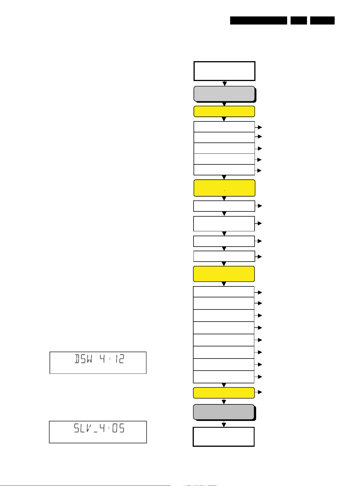
At the beginning of the tests, the DSW version number will be
indicated on the local display of the DVD.
The display will look like the following:
Press the OPEN/CLOSE key to proceed to the next test.
5.2.4 Survey
Press 2 keys simultaneously
<OPEN/CLOSE> + <STOP>
Connect to main
INTERACTIVE TESTS
DISPLAY PCB
DISPLAY TEST
LED TEST
KEYBOARD TEST
REMOTE CONTROL
P50 LOOP BACK TEST
DispDisplay (30a)
DispLed (29)
DispKeyb (27)
DispRc (28)
DispP50 (60)
MONO PCB
DIGITAL PART
PICTURE TEST
SOUND 1 TEST
SCART DVD TEST
SCART LOOP TEST
SOUND 2 TEST
VideoColDencOn (23a)
AudioPinkNoiseOn (20a)
VideoScartSwDvd (55a)
VideoScartSwPass (55b)
AudioSineOn (21a)
MONO PCB(SERVO)
& BASIC ENGINE
VERSION NUMBER
TRAY TEST
SLEDGE TEST
DISC MOTOR TEST
FOCUS TEST
RADIAL TEST
BeVer (37)
BeTrayOut/In (43a/b)
BeSledgeOut/In (41a/b)
BeDiscMotorOn (39a/b)
BeFocusOn (38a/b)
BeRadialOn (40a/b)
JUMP TEST
Figure 5-3
CL 16532162_028.eps
080102
TRAY TEST
ERROR LOG & BITS
Pressing the PLAY key will proceed to the slave S/W version
display, which is shown on the local display of the DVD player.
The display will look like the following:
CL 16532162_029.eps
080102
Figure 5-4
LOOP TEST
To exit player test,
disconnect from mains
BeGroovesIn/Mid/Out (42a/b/c)
BeTrayOut/In (43a/b)
LogReadErr (31)
LogReadbits (32)
= Dealer script exclusive of test2
CL 16532162_030.eps
Figure 5-5
090102
EN 24 DVD 723-7435.
Y
5.3 Display PCB
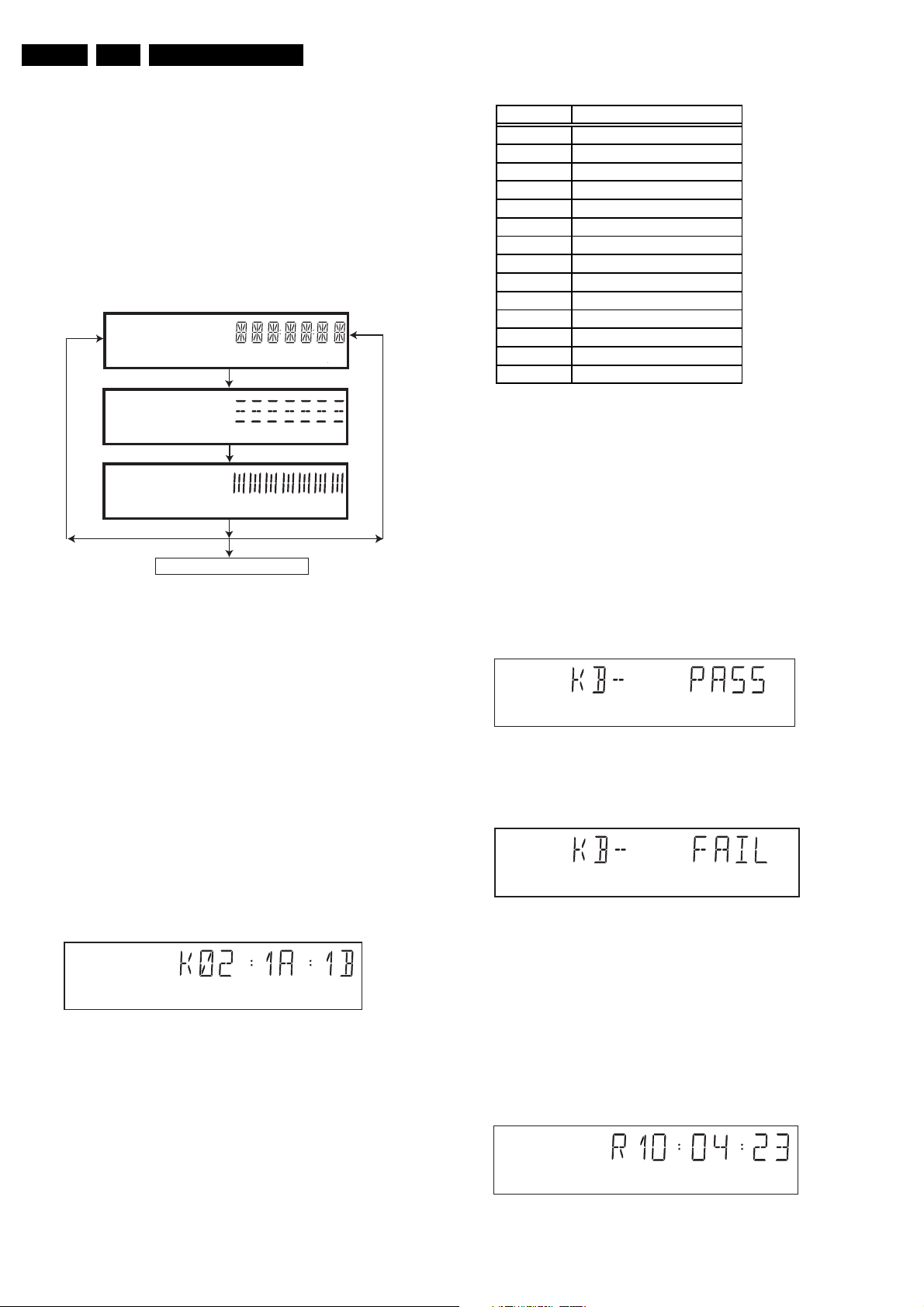
5.3.1 Display Test
The display test is performed by nucleus DispDisplay. By
putting a serie of test patterns on the local display, the local
display is tested. To step through all different patterns, the user
must either press OPEN/CLOSE (pattern is ok) or STOP
(pattern was incorrect) to proceed to the next pattern. The
display of patterns is continued in a cyclic manner, shown in
Fig. 5-6, until the user presses PLAY. If the user presses PLAY
before all display patterns are tested, the DispDisplay nucleus
will return FALSE (display test unsuccessful).
If OK, press OPEN/CLOSE
If NOK, press STOP
Diagnostic Software, Trouble Shooting and Test Instructions
KEY ID KE
0 PLAY/PAUSE
1 STOP
2 OPEN/CLOSE
3 STANDBY
4 NEXT
5 PREVIOUS
7 SMART PICTURE
8 NAVIGATION -UP
9 NAVIGATION -DOWN
A NAVIGATION - LEFT
B NAVIGATION - RIGHT
C DISC MENU
DOK
E SOUND
CL 26532039_027.eps
203020
If OK, press OPEN/CLOSE
If OK, press OPEN/CLOSE
press PLAY to continue
If NOK, press STOP
If NOK, press STOP
CL 16532162_031.eps
Figure 5-6
5.3.2 LED Test
The LED(s) on the DVD player is (are) tested by nucleus
DispLed. The user must check if the LED(s) is (are) lighted; if it
is, press OPEN/CLOSE, if it is not, press STOP. By pressing
PLAY the script will proceed to the next test. If the user presses
PLAY before OPEN/CLOSE or STOP, the DispLed nucleus will
return TRUE (LED test successful).
5.3.3 Keyboard Test
The keyboard of the DVD player is tested by nucleus
DispKeyb. The user is expected to press all keys on the local
keyboard once. The code of the key pressed is shown on the
local display (1 hexadecimal digit) immediately followed by a
(hexadecimal) number indicating how many times that key has
been pressed. Example of the local display during this test:
080102
Figure 5-8
If any keys are detected more than once (due to hardware
error), the key-code is displayed twice (or more), with the
second digit increased by 1.
If the user does not press all keys minimally once (in any order),
the DispKeys nucleus will return FALSE and cause an error in
the overall result of the player script.
The user can leave the keyboard test by pressing the PLAY key
on the local display of the DVD player for at least one full
second.
The result of the keyboard test is shown on local display as
follows:
CL 16532162_033.eps
080102
Figure 5-9
Or
CL 16532162_034.eps
080102
Figure 5-10
Figure 5-7
The key-codes displayed on the local display will scroll from
right to left when the display gets full, the text "K" will remain
on display.
CL 196532162_032.eps
080102
Pressing PLAY on the local keyboard again will proceed to the
next text.
5.3.4 Remote Control Test
The remote control of the DVD player is tested by nucleus
DispRc. The user must press any key on the remote control just
once. The codes of the key pressed will be shown on the local
display in hexadecimal format. Example:
Figure 5-11
CL 16532162_035.eps
140102
 Loading...