

Philips DVD-580-M Service manual
DVD-Video Player DVD580M
DVD580M /691 /001
Contents Page
1 Technical Specs and Connection Facilities 2
2 Safety Instructions, Warnings, Notes, and Service
Hints 3
3 Directions for Use 4
4 Mechanical- and Dismantling Instructions 13
5 Diagnostic Software, Trouble Shooting and Test
Instructions(Not Applicable) 17
6 Wiring-, Block Diagrams
Block Diagram 29
Wiring Diagram 30
7 Electrical Diagrams and Print-Layouts Diagram PWB
Power Board 31 32
Front Board 33 34
Decoder Board: Processor and Memory 35 37-38
Decoder Board: Audio Interface 36 37-38
AV Board (NON-EU) 39 40
AV Scart Board (EU) 41 42
Karaoke Board 43 43
8 Alignments(Not Applicable) 45
9 Circuit Descriptions 45
10 Spare Parts List 53
CL 26532085_000.eps
180702
©
Copyright 2002 Philips Consumer Electronics B.V. Eindhoven, The Netherlands.
All rights reserved. No part of this publication may be reproduced, stored in a
retrieval system or transmitted, in any form or by any means, electronic,
mechanical, photocopying, or otherwise without the prior permission of Philips.
Published by MW 0267 Service PaCE Printed in the Netherlands Subject to modification EN 3122 785 12290
EN 2 DVD580M1.
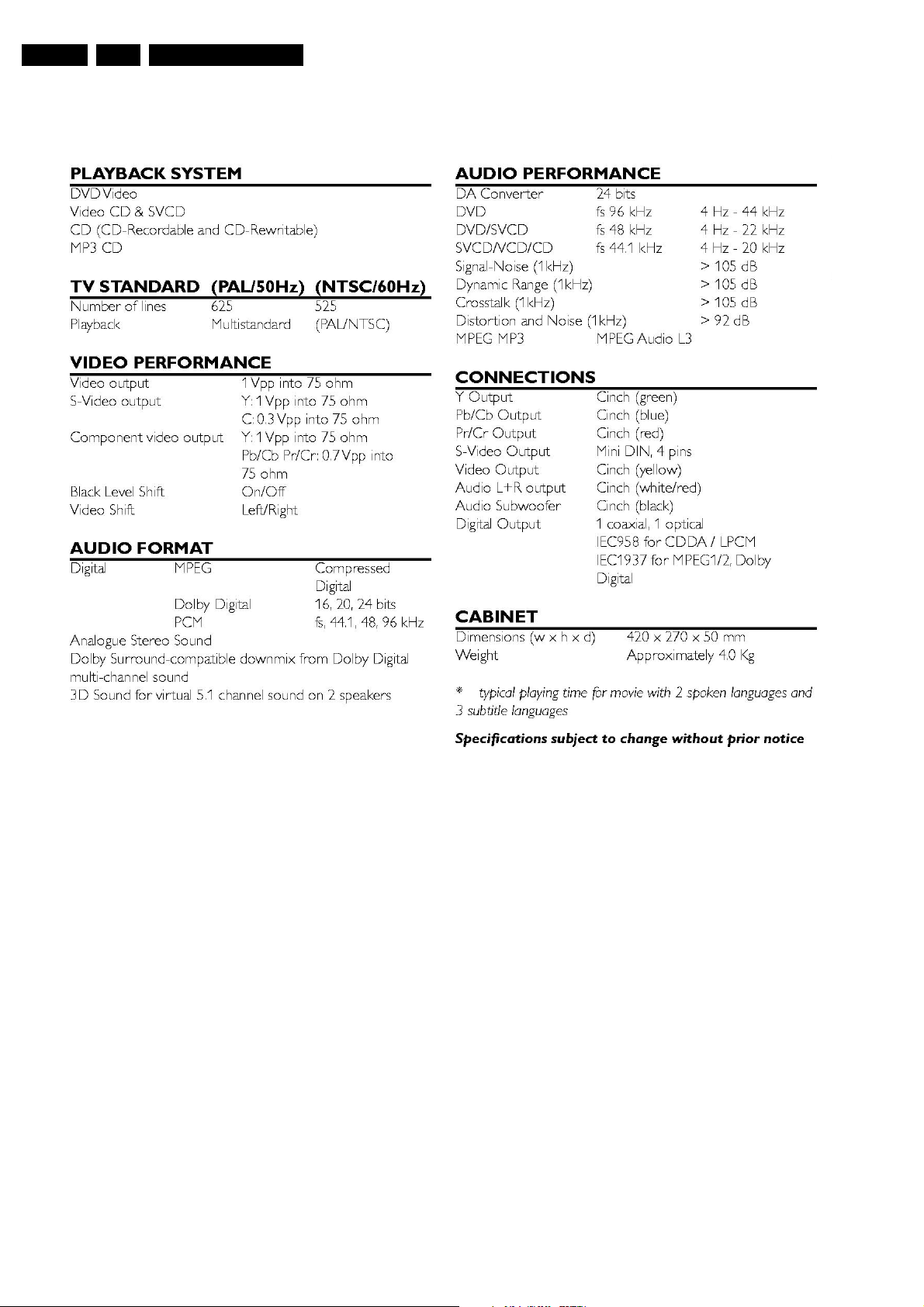
Technical Specifications
1. Technical Specifications
CL 26532085_073.eps
180702
Safety Instructions, Warnings, Notes, and Service Hints
2. Safety Instructions, Warnings, Notes, and Service Hints
EN 3DVD580M 2.
2.1 Safety Instructions
2.1.1 General Safety
Safety regulations require that during a repair:
• Connect the unit to the mains via an isolation transformer.
• Replace safety components, indicated by the symbol ,
only by components identical to the original ones. Any
other component substitution (other than original type) may
increase risk of fire or electrical shock hazard.
Safety regulations require that after a repair, you must return
the unit in its original condition. Pay, in particular, attention to
the following points:
• Route the wires/cables correctly, and fix them with the
mounted cable clamps.
• Check the insulation of the mains lead for external
damage.
• Check the electrical DC resistance between the mains plug
and the secondary side:
1. Unplug the mains cord, and connect a wire between
the two pins of the mains plug.
2. Set the mains switch to the 'on' position (keep the
mains cord unplugged!).
3. Measure the resistance value between the mains plug
and the front panel, controls, and chassis bottom.
4. Repair or correct unit when the resistance
measurement is less than 1 MΩ.
5. Verify this, before you return the unit to the customer/
user (ref. UL-standard no. 1492).
6. Switch the unit ‘off’, and remove the wire between the
two pins of the mains plug.
2.1.2 Laser Safety
This unit employs a laser. Only qualified service personnel may
remove the cover, or attempt to service this device (due to
possible eye injury).
2.2 Warnings
2.2.1 General
• All ICs and many other semiconductors are susceptible to
electrostatic discharges (ESD, "). Careless handling
during repair can reduce life drastically. Make sure that,
during repair, you are at the same potential as the mass of
the set by a wristband with resistance. Keep components
and tools at this same potential. Available ESD protection
equipment:
– Complete kit ESD3 (small tablemat, wristband,
connection box, extension cable and earth cable) 4822
310 10671.
– Wristband tester 4822 344 13999.
• Be careful during measurements in the live voltage section.
The primary side of the power supply (pos. 1005), including
the heatsink, carries live mains voltage when you connect
the player to the mains (even when the player is 'off'!). It is
possible to touch copper tracks and/or components in this
unshielded primary area, when you service the player.
Service personnel must take precautions to prevent
touching this area or components in this area. A 'lightning
stroke' and a stripe-marked printing on the printed wiring
board, indicate the primary side of the power supply.
• Never replace modules, or components, while the unit is
‘on’.
2.2.2 Laser
• The use of optical instruments with this product, will
increase eye hazard.
• Only qualified service personnel may remove the cover or
attempt to service this device, due to possible eye injury.
• Repair handling should take place as much as possible
with a disc loaded inside the player.
• Text below is placed inside the unit, on the laser cover
shield:
Laser Device Unit
Type : Semiconductor laser
GaAlAs
Wavelength : 650 nm (DVD)
: 780 nm (VCD/CD)
Output Power : 20 mW (DVD+RW
writing)
:0.8 mW (DVD
reading)
: 0.3 mW (VCD/CD
reading)
Beam divergence : 60 degree
Figure 2-1
Note: Use of controls or adjustments or performance of
procedure other than those specified herein, may result in
hazardous radiation exposure. Avoid direct exposure to beam.
CAUTION VISIBLE AND INVISIBLE LASER RADIATION WHEN OPEN AVOID EXPOSURE TO BEAM
ADVARSEL SYNLIG OG USYNLIG LASERSTRÅLING VED ÅBNING UNDGÅ UDSÆTTELSE FOR STRÅLING
ADVARSEL SYNLIG OG USYNLIG LASERSTRÅLING NÅR DEKSEL ÅPNES UNNGÅ EKSPONERING FOR STRÅLEN
VARNING SYNLIG OCH OSYNLIG LASERSTRÅLNING NÄR DENNA DEL ÄR ÖPPNAD BETRAKTA EJ STRÅLEN
VARO! AVATTAESSA OLET ALTTIINA NÄKYVÄLLE JA NÄKYMÄTTÖMÄLLE LASER SÄTEILYLLE. ÄLÄ KATSO SÄTEESEEN
VORSICHT SICHTBARE UND UNSICHTBARE LASERSTRAHLUNG WENN ABDECKUNG GEÖFFNET NICHT DEM STRAHL AUSSETSEN
DANGER VISIBLE AND INVISIBLE LASER RADIATION WHEN OPEN AVOID DIRECT EXPOSURE TO BEAM
ATTENTION RAYONNE MENT LASER VISIBLE ET INVISIBLE EN CAS D'OUVERTURE EXPOSITION DANGEREUSE AU FAISCEAU
!
Figure 2-2
2.2.3 Notes
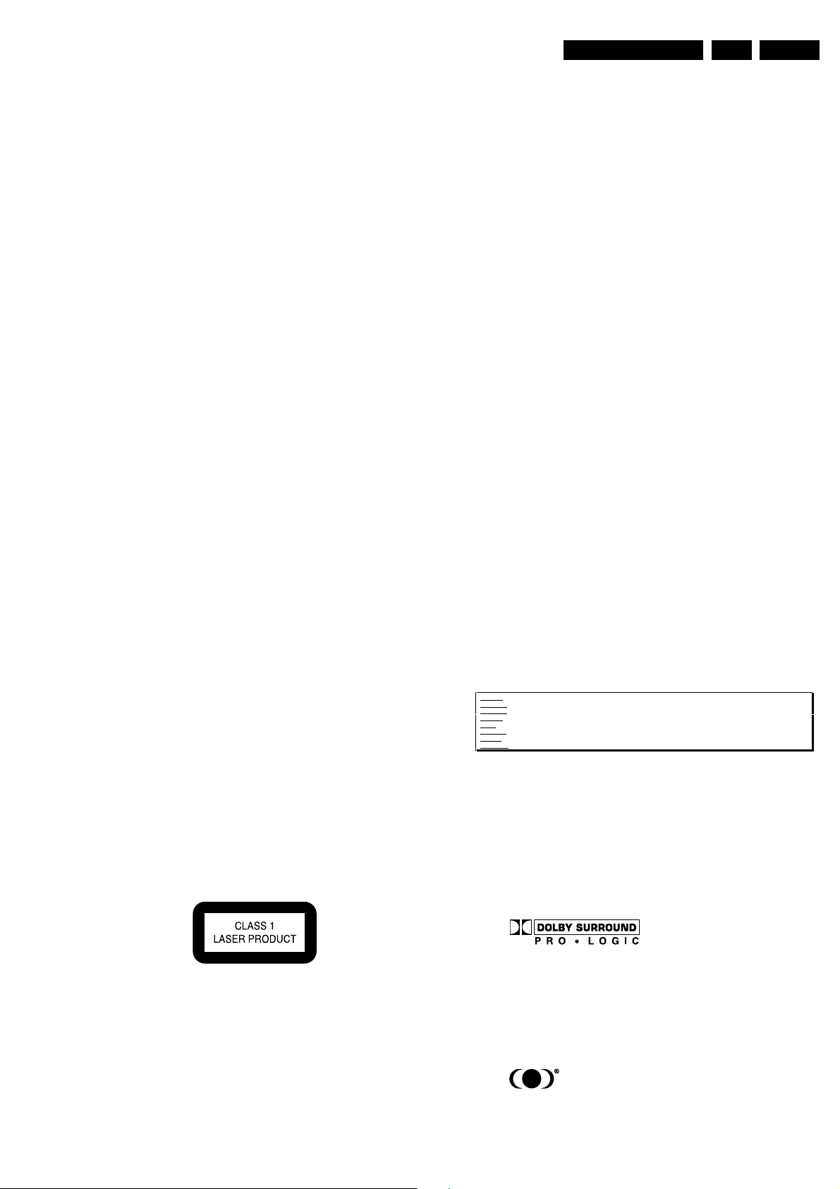
Dolby
Manufactered under licence from Dolby Laboratories. “Dolby”,
“Pro Logic” and the double-D symbol are trademarks of Dolby
Laboratories. Confidential Unpublished Works. ©1992-1997
Dolby Laboratories, Inc. All rights reserved.
Figure 2-3
Trusurround
TRUSURROUND, SRS and symbol (fig 2-4) are trademarks of
SRS Labs, Inc. TRUSURROUND technology is manufactured
under licence frm SRS labs, Inc.
Figure 2-4
EN 4 DVD580M3.
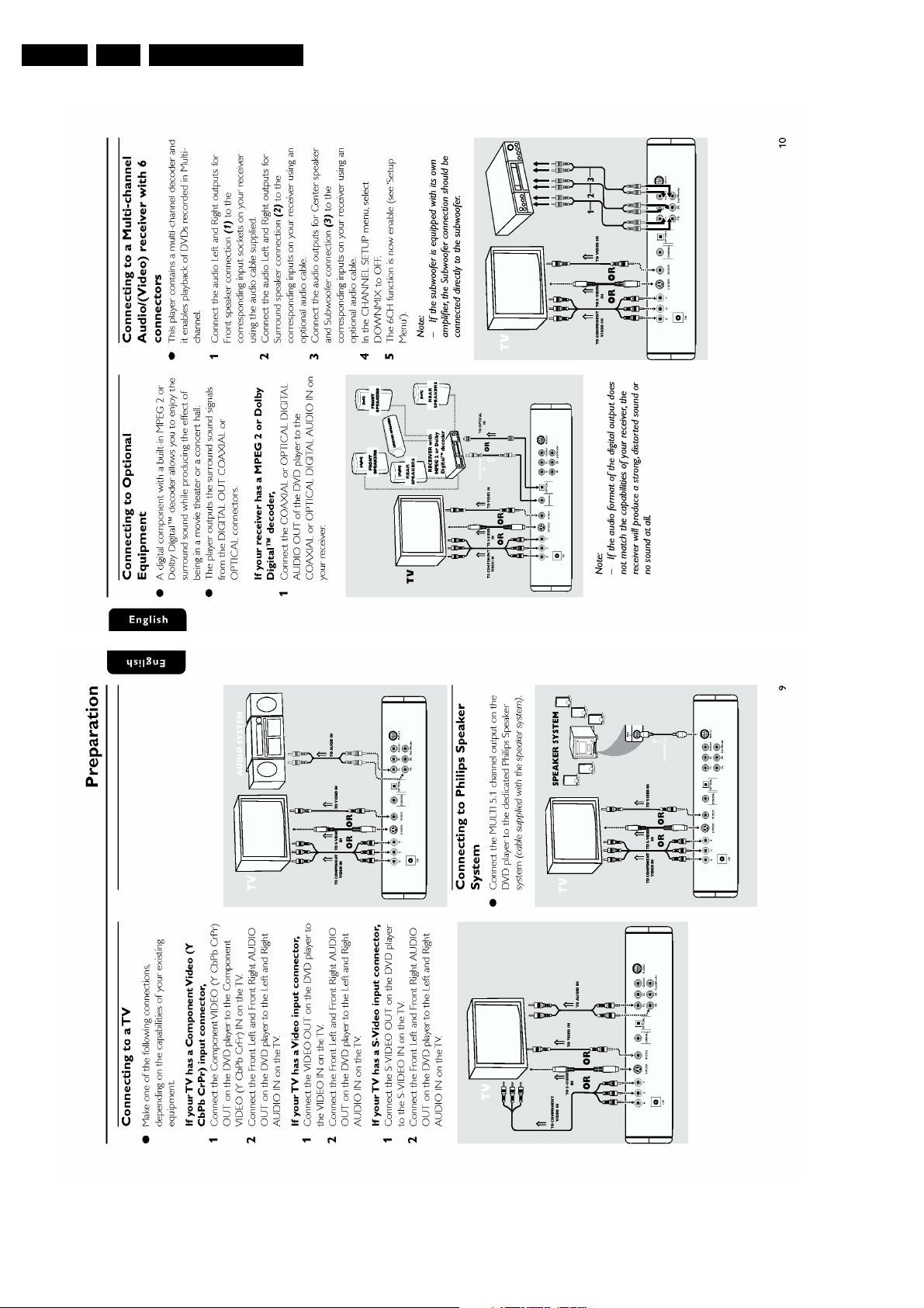
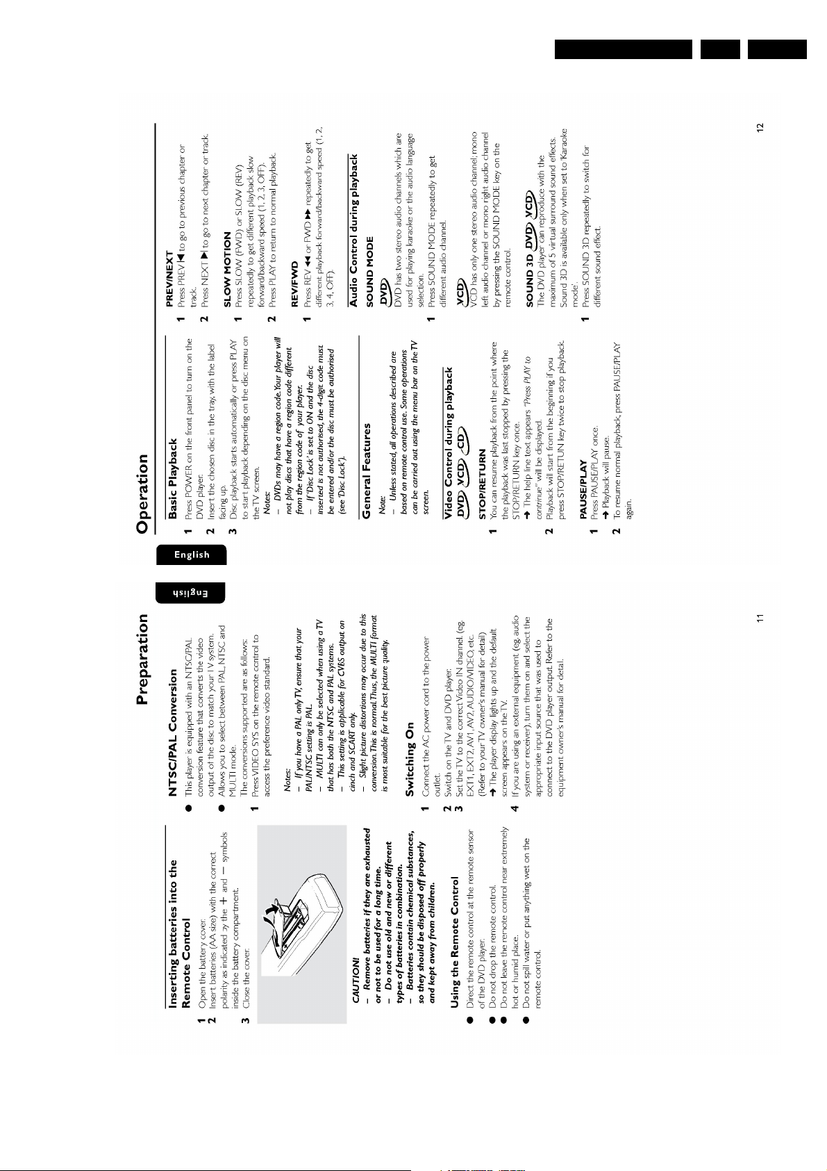
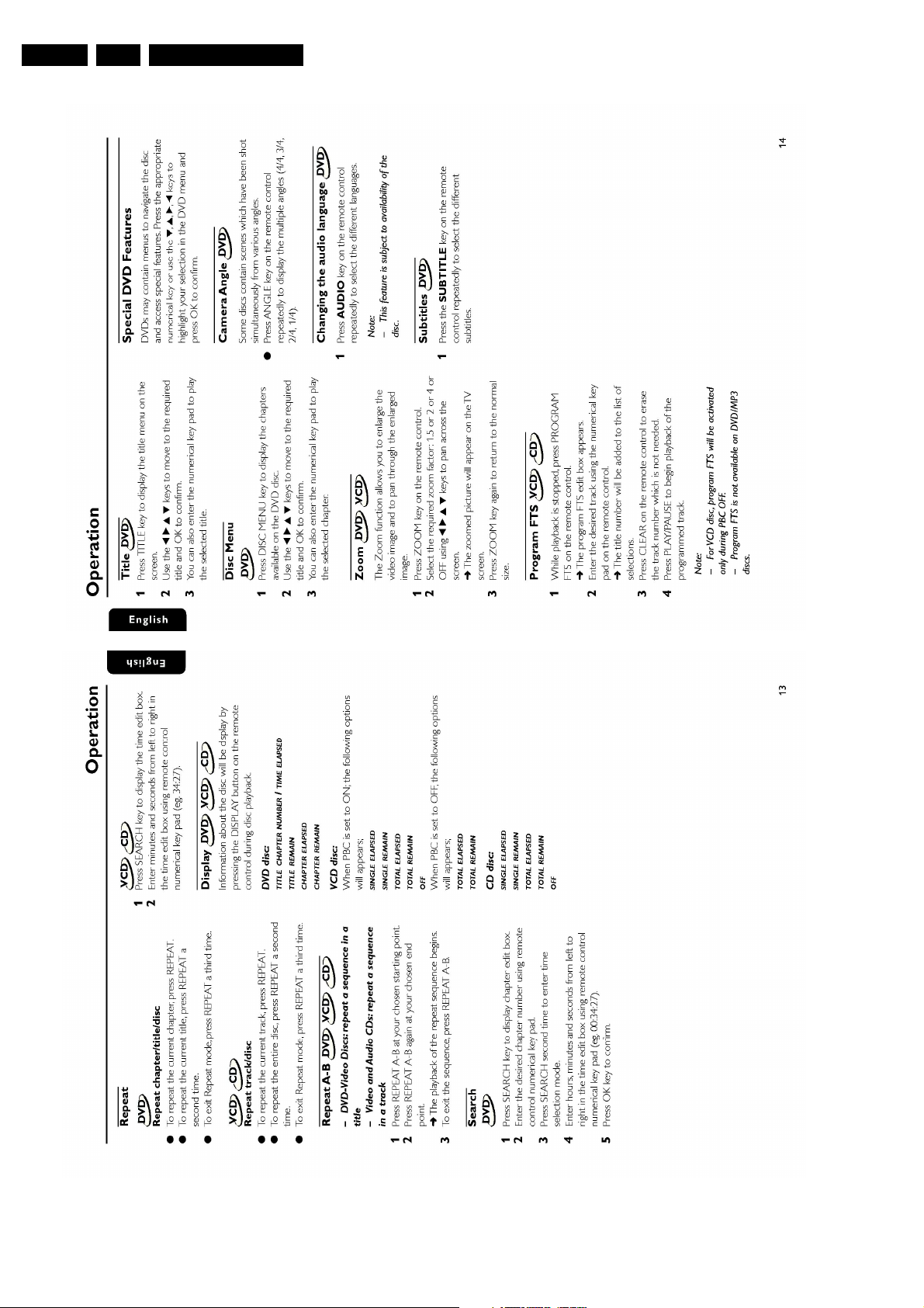
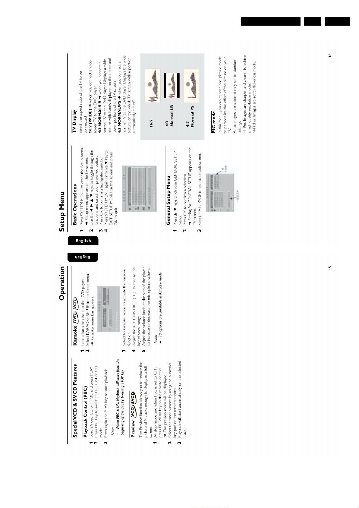
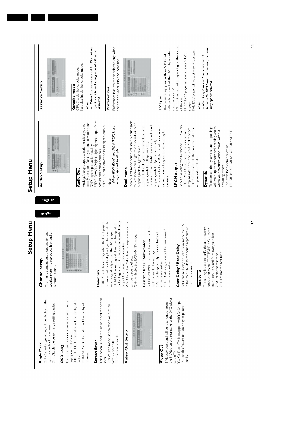
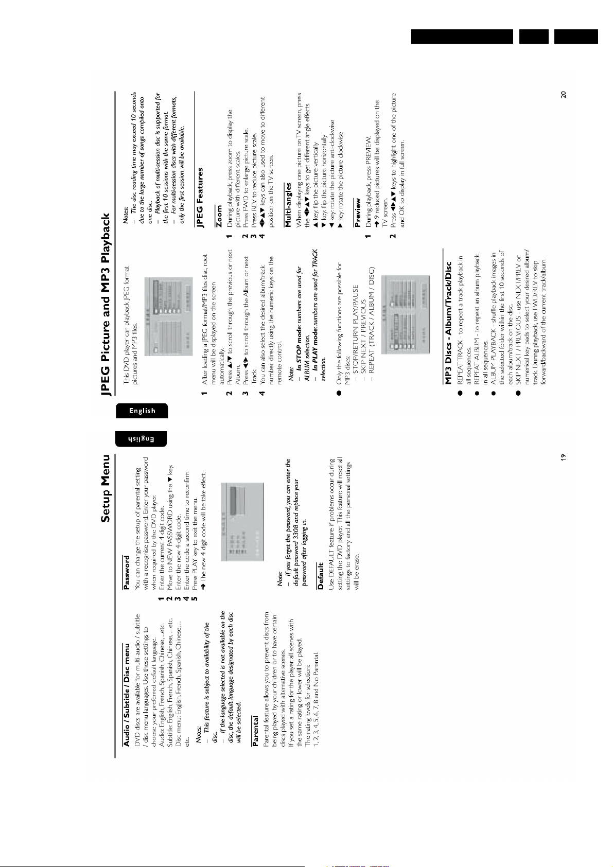
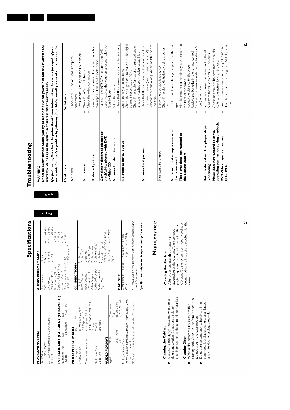
3. Directions for Use
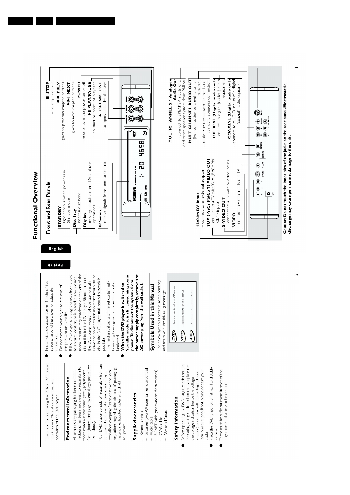
Directions for Use

Directions for Use
EN 5DVD580M 3.
EN 6 DVD580M3.
Directions for Use
Directions for Use
EN 7DVD580M 3.
EN 8 DVD580M3.
Directions for Use
Directions for Use
EN 9DVD580M 3.
EN 10 DVD580M3.
Directions for Use
Directions for Use
EN 11DVD580M 3.
EN 12 DVD580M3.
Directions for Use
Mechanical- and Dismantling Instructions
4. Mechanical- and Dismantling Instructions
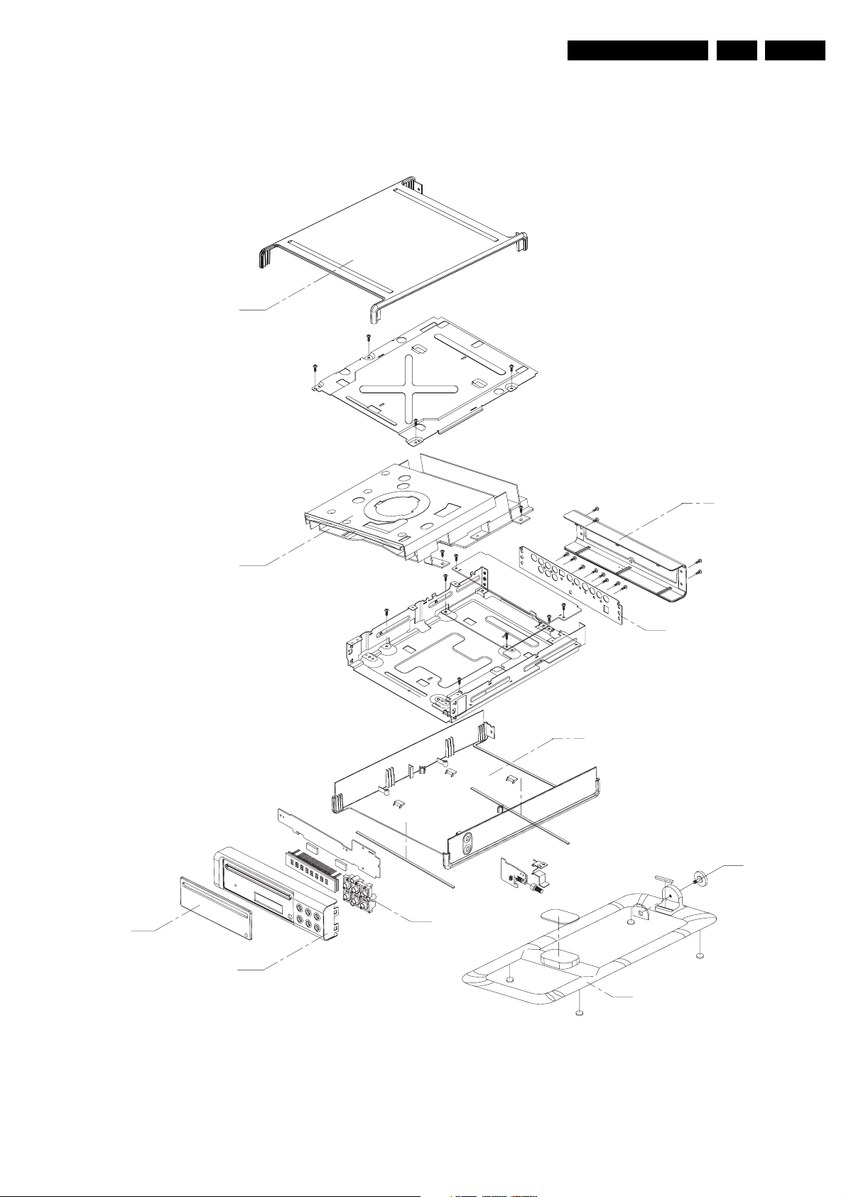
1014
CAB. UPPER
EN 13DVD580M 4.
1003
LOADER TD-S202
1011
CAB. BACK
1037
BACKPLATE
1013 CAB. LOWER
1040
LOCKNUT
1016
LENS
1012
FRONT PANEL
1015
FUNCTION KEY
Figure 4-1 Exploded View
1038
STAND
CL 26532085_058.eps
160702
EN 14 DVD580M4.
Mechanical- and Dismantling Instructions
4.1 Dismantling Instruction
In this paragraph some tips are given to dismantle the
DVD580M player. For item number, refer to the exploded view.
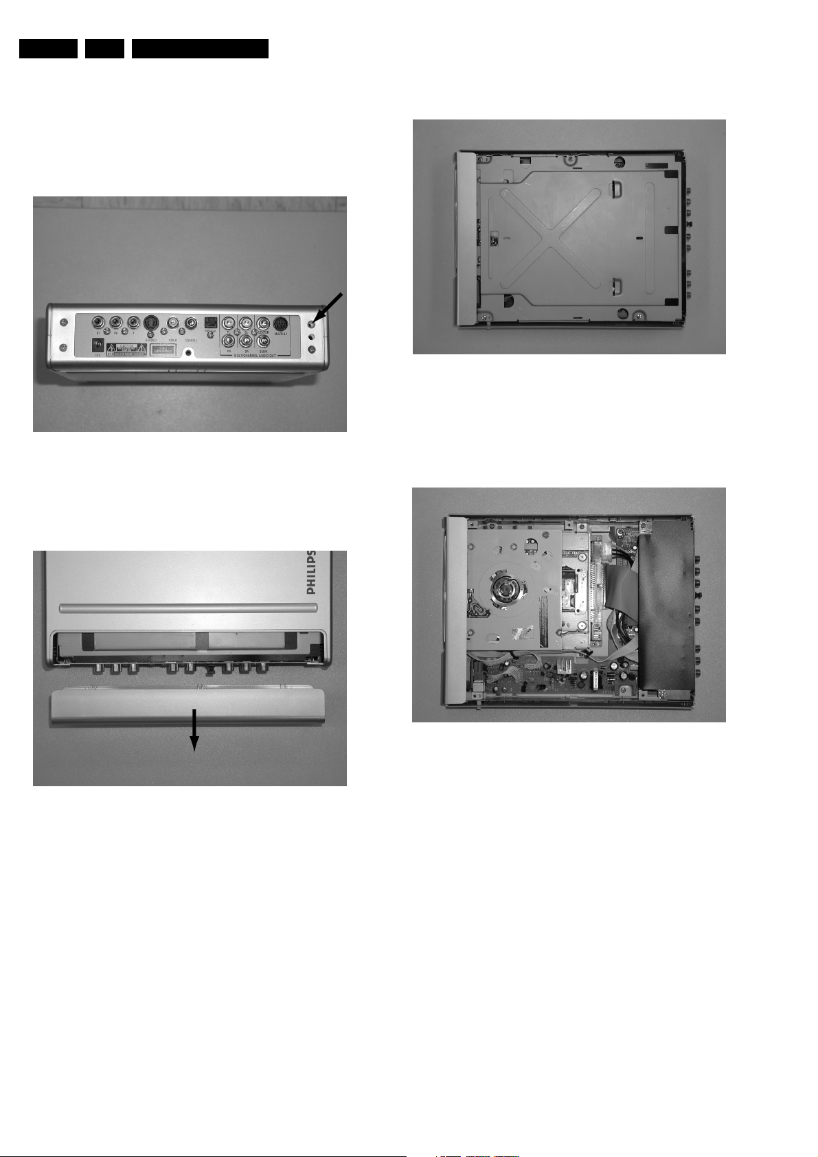
4.1.1 Remove 4 screws at the rear cover (1011)
CL 26532085_020.eps
180702
4.1.3 Inner metal plate will be seen after removing the top cover.
CL 26532085_009.eps
100702
Figure 4-4 Remove Top Cover
4.1.4 Remove the metal plate, the loader (1003) and other modules will be visable.
Figure 4-2 Back View
4.1.2 Push the top cover(1014) toward the rear.
CL 26532085_021.eps
Figure 4-3 Back Panel Detached
180702
Figure 4-5 Remove Inter Top
CL 26532085_017.eps
100702
Mechanical- and Dismantling Instructions
EN 15DVD580M 4.
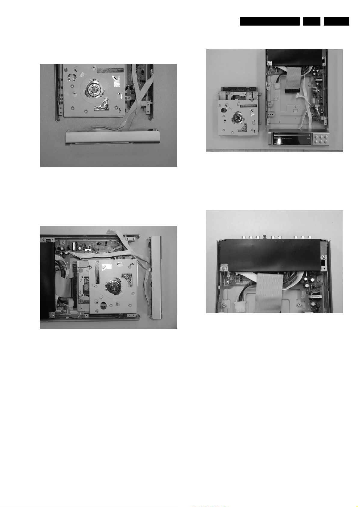
4.1.5 Use a small flat tip screw driver to release the snaps on the
front panel (1012) and gently pull the panel out from the
set.
CL 26532085_018.eps
100702
Figure 4-6 Remove Front Panel
4.1.6 Remove 4 screws at both sides of the loader (1003) and disconnect 2 wire connections.
Now the loader(1003) is removed.
CL 26532085_014.eps
100702
Figure 4-8 LP Separate
4.1.7 Remove the AV board by removing 2 screws and the cover plate (1037).
Figure 4-7 Remove Loader
CL 26532085_015.eps
100702
CL 26532085_012.eps
Figure 4-9 Output Board Top View
100702
EN 16 DVD580M4.
Mechanical- and Dismantling Instructions
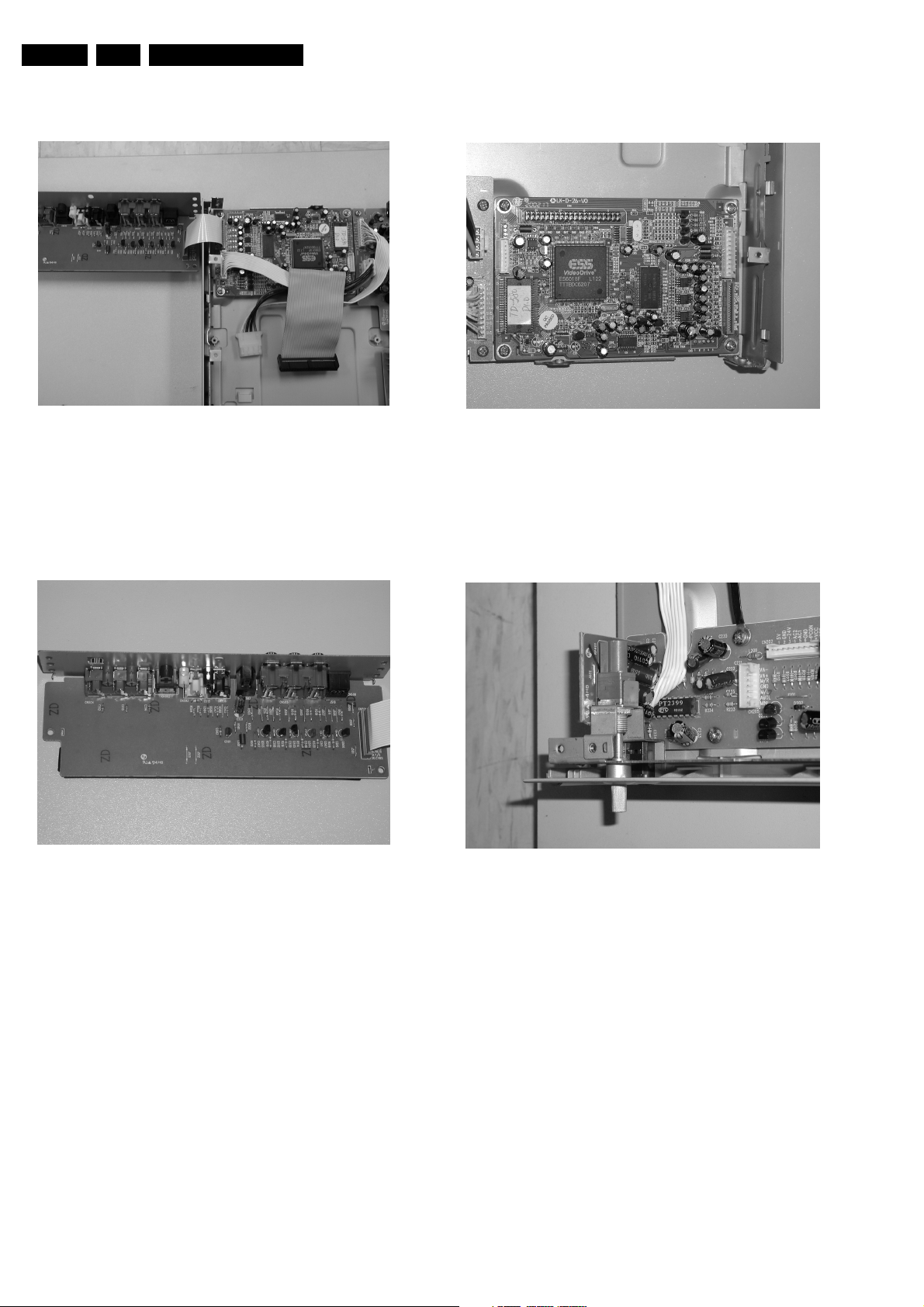
When the AV board is removed, the decoder board will be
visable.
Figure 4-10 Output PCB open
4.1.8 Pictures below view on the modules.
AV board
CL 26532085_011.eps
100702
Decoder board
Figure 4-12 Decoder Board
Karaoke
CL 26532085_019.eps
100702
Figure 4-11 Video Board
CL 26532085_008.eps
100702
Figure 4-13 Karaoke Board
CL 26532085_016.eps
100702

Diagnostic Software, Trouble Shooting and Test Instructions
5. Diagnostic Software, Trouble Shooting and Test Instructions
EN 17DVD580M 5.
5.1 Service Hints
5.1.1 Repair Tips
DVD Engine
The DVD Engine is a non-repairable unit and in case of failure,
it has to be replaced with a complete Engine.
Encoder, Switched Mode Power Supply, Karaoke, and Front Display Board
All the boards have to be repaired down to component level.
5.1.2 Change of Region Code
The region code can be change according to the following
procedure:
1. Press button on the front of the player.
2. Enter the 4-digit code <1> <3> <5 <6> on the remote
control.
3. Enter one of the keys below to change the software setting.
REGION CODE:
– USA ==> 1
– EUROPE ==> 2
– AP ==> 3
– LATAM ==> 4
– INDIA / RUSSIA ==> 5
– CHINA ==> 6
4. Press button on the remote control for 5 times.
5. The change should effect immediately with information
indicated on TV screen.
5.1.3 Software Upgrade via Download Disc
5.1.5 ComPair
There is no ComPair available for DVD580M player
5.2 Trouble Shooting
In this paragraph some troubleshooting tips are given to
diagnos the DVD580M player. For detailed diagnostics, check
the faulting tree since no built-in diagnostic software is
available in the player.
5.2.1 DVD Engine
The DVD engine is a non-repairable component. Hence, it is
necessary to determine if any fault condition of the player is
caused by the DVD engine before replacing it.
The engine is a stand-alone system, an integrated unit of Slot
loader and servo board, which does not need to be connected
to the decoder board to perform it basic operations. Once a
stable voltage is supplied to the engine,some mechanical
movement will be observed. Hence, to determine whether the
engine is faulty, remove the 40 pins flex cable and observe the
mechanical movement. If no mechanical movement is
observed, the engine should be faulty and it should be
reconfirmed with a working engine.
The Slot Loader has an optical unit consisting of two lasers,
one for CD with a wavelength of 780 nm, and one for, DVD with
a wavelength of 650 nm. If any one type of disc (DVD or VCD /
CD) cannot be identified by the player, it can be sure that the
fault is due to the engine.
The application software can be flashed into the DVD player by
means
of a CD-ROM disc. The CD-ROM disc has to be made with a
CD writer.
Note: Ensure the filename used for making the CDR must be
identical to the application software file name as display in the
player.
Application Software
1. Insert the DOWNLOAD DISC into the player.
2. The upgrading operation will start automatically.
3. Once the DOWNLOAD DISC is recognized, the player will
display the filename on the TV screen.
4. The word will flash on the TV screen indicates the
progress.
5. Once when the upgrading is completed, the word will
display momentary on the TV screen.
6. The TV screen will become BLUE and the player will goes
into standby mode.
5.1.4 Verify Setting
To check that the setting has change successfully.
1. Press button on the front of the player.
2. Press button on the remote control while display shown
EJECT.
3. Two lines text will appear on the TV screen. That is how it
looks like.
– TD580A.00B
– TDDVD580V02-ES
4. In the text, the following numbers refer to:
– TD580A.00B ==> refer to application software
filename.
– TDDVD580V02-ES ==> refer to application software
version.
EN 18 DVD580M5.
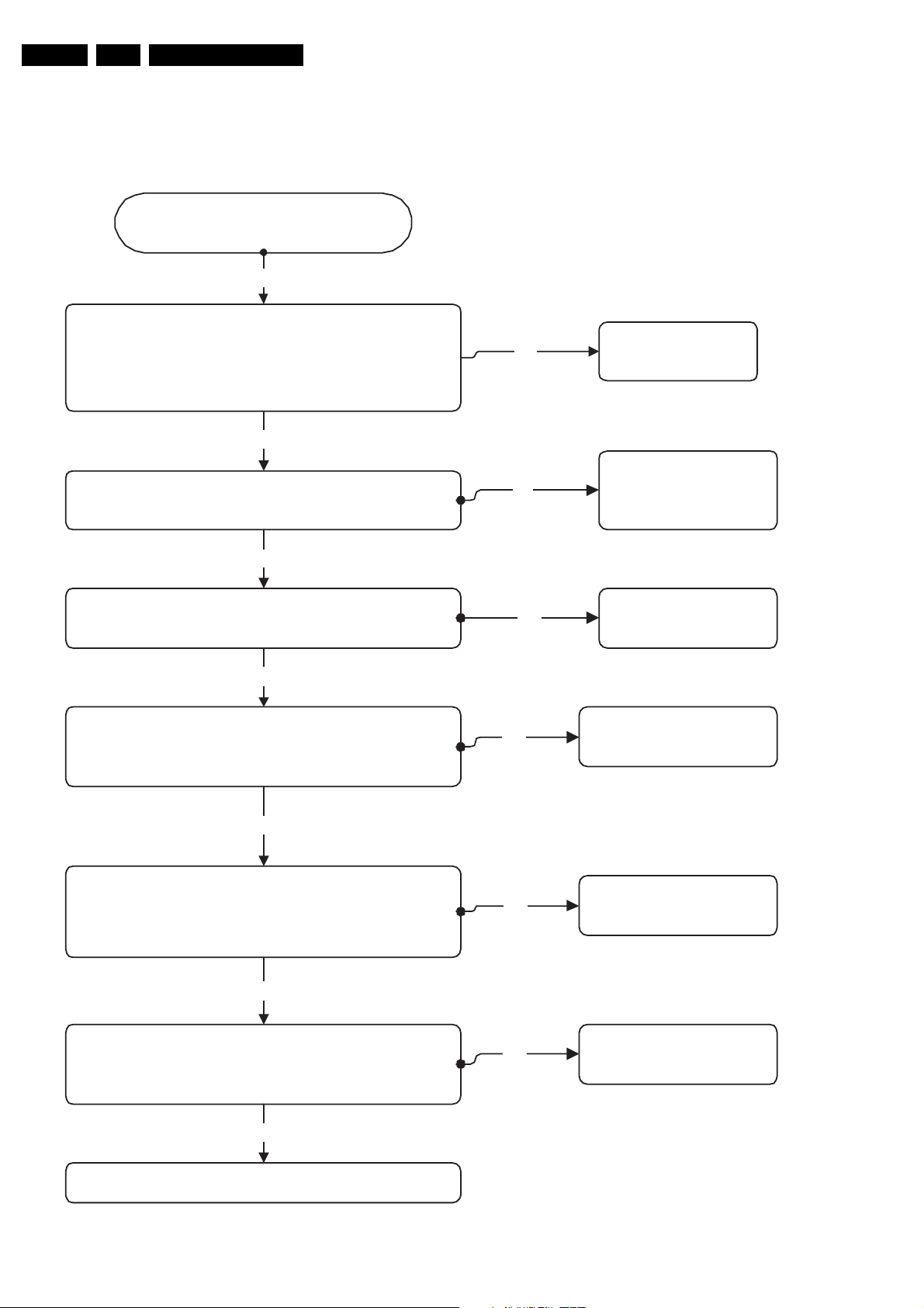
5.3 Fault Finding Trees
5.3.1 No Operation
Standby LED does not light,
The player does not operates
Check point :
The output voltage of VCC is 5 V + / - 5 %.
Observe:
If the LED can be lighted up again when the R314 on front panel
board is short circuit manually.
Go
No
Diagnostic Software, Trouble Shooting and Test Instructions
Ye s
Solution:
Replace the R314
Check point :
The 11V at the output of IC U201 pin number 3.
Observe : N/A
Ye s
Check point :
The input side of R201 is over 11V.
Observe : N/A
No
Check point :
Short circuit the terminals of L 203.
Observe :
The operation can be restored.
No
Check point :
Short circuit the pin number 3 and 4 of the L 201.
Observe :
The operation can be restored.
Ye s
Ye s
No
Ye s
Solution :
Replace the IC U201
Solution :
Replace the resistor R201
Solution :
Replace the coil L203
Solution :
Replace the coil L201
Check point :
Check the FUSE 2 01
Observe :
FUSE is burn
No
No
Replace the External PSU
Figure 5-1
Ye s
Solution :
Replace the FUSE
CL 26532085-060.eps
180702
 Loading...