

Philips DUS804C-UP Installation Manual
DUS804C-UP
Ceiling Mount Universal Sensor Installation Manual
This unit is for indoor use only. This unit is designed for installation in a 64mm diameter hole where the ceiling void is at
least 40mm deep. Select an appropriate indoor mounting location, as detailed in the location guidelines on the following
The DUS804C-UP is a low profile mount 360º ceiling mount sensor that combines motion detection via
both Ultrasonic (UP) & passive inferred (PIR), infra red remote control reception (IR) and ambient light
level detection (PE) in the one device.
In applications such as office buildings, lecture theatres, and homes, the DUS804C-UP universal sensor
can be utilised to detect motion and switch on the lights automatically when motion is detected. When
rooms have been unoccupied for a certain amount of time, lights can be automatically dimmed or switched
off to provide energy savings.
The unit also incorporates a segmented click-up bezel surrounding the motion sensor element. This
enables a portion of the sensing field to be readily masked to prevent nuisance detection from adjacent
doorways or corridors. The same sensor provides IR control reception to enable full remote control over
lights, audio-visual equipment and blinds. A range of hand held infra-red transmitters to complement
DUS804 series universal sensors are available.
In situations where it is critical to maintain precise lighting control for individual workspaces, such as an
office workstation or even air traffic control centers, the DUS804C-UP facilitates light compensation. The
DUS804C-UP can also perform multiple functions at the same time so that automatically going to “Daylight
Harvesting” mode once motion has been detected for additional energy savings.
instructions
2 DUS804C-UP Installation Manual Rev D.docx
pages. Note that the product has two functions, and the optimum mounting location for each individual function may
conflict with each other, and may require use of multiple sensors.
DUS804C NETWORK CONNECTIONS
:
Motion detection installation steps
• An ultrasonic sensor should never be located within 17.5 meters of another ultrasonic sensor.
• Chose a location where it may face doorways etc which could cause false triggering.
• Position the sensor so it is between 2.1 and 4.0m from the floor. Optimum height is 2.4m
• Position the sensor so it is at least 1m away from electrical lighting such as neon and fluorescent lights
• Position the sensor as to avoid exposing it to direct sunlight. Sensor should be at least 2.5m from horizontal or
vertical air ducts
• Position the sensor where pedestrian traffic is likely to walk across the detection zones
• Fix the sensor to a firm section of ceiling. Sensor can be surface mounted using ring provided.
• Note that for the DUS804C-UP coverage area is rectangular (see Motion Detector coverage diagram)
• When terminated and power there are three indicating LED‟s for the following information
o Blue = Low network voltage. The sensor must receive minimum of 12VDC from the Dynet network. If
the right network voltage is not present at the sensor terminals when the whole system is powered,
then additional network power supplies (DDNP1501) will be required.
o Green = Ultrasonic detection activity
o Red = PIR detection activity
• When terminated correctly and powered from the Dynet network the sensors LED‟s will flash for 5 min every time a
Dynet push button is pressed. This is so the installer can confirm the sensor is terminated correctly with other network
devices.
• Only after all network devices are confirmed to be terminated correctly can the commissioning of the system begin.
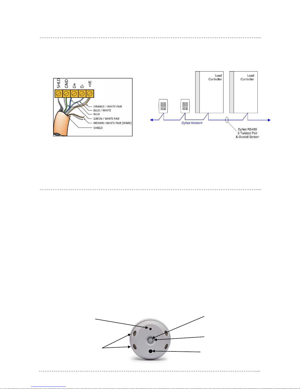
PIR sensor
Network sign
on button & IR
window
Ultrasonic
sensors
Recommended Cable Types
Belden: 9503
Garland: MCP3S
Hartland: HCK603
M&M Cable: B2003CS
Dynalite: DYNET-STP-CABLE
STANDARD CABLE CONNECTION
Recommended Cable Colours
Green/White Pair paralleled for GND
Orange/White Pair paralleled for +VE
Blue/White Pair Blue for DATA +
White for DATA -
Light level sensor
Indicating LED’s
 Loading...