

Page 1

LUXEON Rebel ES
Superior efficacy
Leading lumen output
Ultimate design flexibility
Technical Datasheet DS61
LUXEON® Rebel ES
Leading efficacy and light output, maximum design flexibility.
Introduction
LUXEON
Tested and binned at 700 mA, confidently design LUXEON Rebel ES into high lumen
applications or create more energy efficient devices using the same emitter. Luminaire
manufacturers and designers count on LUXEON Rebel ES for quality, reliability and
in-device performance.
• Broad portfolio of emitters for indoor and outdoor applications
• CCT and CRI combinations to support a wide range of applications
• Highest lumens per watt and lumens per dollar
• Lowest forward voltage
• Industry Standard ANSI color binning
• Superior >125lm/W efficacy enables efficient and sustainable applications
• Industry leading lumen maintenance
®
Rebel ES gives you the flexibility you need for designing luminaires and lamps.
• Complete design resources available to support your application development
Page 2

Table of Contents
General Product Information .................................................................................................................................... 3
Product Nomenclature ........................................................................................................................................ 3
Average Lumen Maintenance Characteristics ................................................................................................. 3
Environmental Compliance ................................................................................................................................. 3
Product Selection
Product Selection for LUXEON Rebel ES.......................................................................................................4
Optical Characteristics
Electrical Characteristics
Absolute Maximum Ratings ................................................................................................................................ 7
JEDEC Moisture Sensitivity ................................................................................................................................. 7
Reflow Soldering Characteristics
Mechanical Dimensions
Pad Configuration .............................................................................................................................................. 10
Solder Pad Design ...............................................................................................................................................10
Relative Spectral Distribution vs. Wavelength Characteristics
Typical Light Output Characteristics
Typical Forward Current Characteristics
Typical Luminous Efficacy
Current Derating Curves
Typical Radiation Patterns
Emitter Pocket Tape Packaging
......................................................................................................................................................... 4
............................................................................................................................................... 5
............................................................................................................................................ 6
............................................................................................................................. 8
.............................................................................................................................................. 9
........................................................................11
.....................................................................................................................15
.............................................................................................................16
......................................................................................................................................... 17
......................................................................................................................................... 19
........................................................................................................................................21
................................................................................................................................22
Emitter Reel Packaging
Product Binning and Labeling
Luminous Flux Bins
4100K Neutral-White Bin Structure .............................................................................................................. 26
5650K Cool-White Bin Structure ................................................................................................................... 27
LUXEON Rebel ES ANSI 1/4th Quadrant Color Bin Structure
ANSI 1/4th quadrant color bin structure for LXW9-PW27, LXW9-PW30, LXW8-PW35,
LXW8-PW40 and LXW8-PW50 emitters ....................................................................................................29
LUXEON Rebel ES ANSI 1/4th Quadrant Bin Structure
ANSI 1/4th quadrant bin structure for LXH7-PW40 emitter ..................................................................32
Forward Voltage Bins
LUXEON Rebel ES Datasheet DS61 20110511 2
............................................................................................................................................. 23
..................................................................................................................................24
....................................................................................................................................................25
..................................................................... 29
................................................................................. 32
.................................................................................................................................................34
Page 3

General Product Information
Product Nomenclature
LUXEON Rebel ES is tested and binned at 700 mA, with current pulse duration of 20 ms. All characteristic charts where the thermal pad is kept
at constant temperature (25ºC typically) are measured with current pulse duration of 20 ms. Under these conditions, junction temperature and
thermal pad temperature are the same.
The LUXEON Rebel ES family of emitters contain a series of LEDs designed for Illumination applications.
The part number designation for the LXML series is explained as follows: L X M L - A B C B
Where:
A — designates radiation pattern (value P for Lambertian)
B — designates color (W for White)
C — designates color variant (C for Cool-White, N for Neutral-White)
D — designates test current (value 2 for 700 mA)
The part number designation for the LXW8 series is explained as follows: L X W A - B C D E
Where:
A — designates minimum CRI performance (value 8 = 80 minimum and 9 = 90 minimum)
B — designates radiation pattern (value P for Lambertian)
C — designates color (value W = White)
D & E — designates nominal ANSI CCT (value 27 = 2700K, 30 = 3000K, 35 = 3500K, 40 = 4000K and 50 = 5000K)
The part number designation for the LXH7 series is explained as follows: L X H A - B C D E
Where:
A — designates minimum CRI performance (value 7 = 70 minimum)
B — designates radiation pattern (value P for Lambertian)
C — designates color (value W = White)
D & E — designates nominal ANSI CCT (value 40 = 4000K)
Therefore products tested and binned at 700 mA follow the part numbering scheme: L X M L - P W x 2, L X W x - P W x x and L X H 7 - P W x x
Average Lumen Maintenance Characteristics
Lumen maintenance for solid state lighting devices (LEDs) is typically defined in terms of the percentage of initial light output remaining after a
specified period of time. Philips Lumileds projects that LUXEON Rebel ES products will deliver, on average, 70% lumen maintenance (L70) at 50,000
hours of operation at a forward current of 1000 mA. This projection is based on constant current operation with junction temperature maintained
at or below 135°C. This performance is based on independent test data, Philips Lumileds historical data from tests run on similar material systems,
and internal LUXEON reliability testing. Observation of design limits included in this data sheet is required in order to achieve this projected lumen
maintenance.
Environmental Compliance
Philips Lumileds is committed to providing environmentally friendly products to the solid-state lighting market. LUXEON Rebel ES is compliant to
the European Union directives on the restriction of hazardous substances in electronic equipment, namely the RoHS and REACH directives. Philips
Lumileds will not intentionally add the following restricted materials to the LUXEON Rebel ES: lead, mercury, cadmium, hexavalent chromium,
polybrominated biphenyls (PBB) or polybrominated diphenyl ethers (PBDE).
LUXEON Rebel ES Datasheet DS61 20110511 3
Page 4

Product Selection
Product Selection for LUXEON Rebel ES
Thermal Pad Temperature = 25°C
Table 1.
Performance at Test Current
Minimum Luminous
Nominal CCT/ Flux Test Current
Color Part Number Minimum CRI Typical CRI (lm)
4100K Neutral-White LXML-PWN2 60 65 200 700
5650K Cool-White LXML-PWC2 60 70 200 700
2700K LXW9-PW27 90 95 120 700
3000K LXW9-PW30 90 95 120 700
3500K LXW8-PW35 80 85 160 700
4000K LXH7-PW40 70 75 180 700
4000K LXW8-PW40 80 85 170 700
5000K LXW8-PW50 80 85 180 700
Notes for Table 1:
1. Minimum luminous flux performance within published operating conditions. Philips Lumileds maintains a tolerance of ± 6.5% on luminous flux
measurements.
[1] [2]
(mA)
Typical Luminous Flux Characteristics at 350 mA, 700 mA and 1000 mA
for LUXEON Rebel ES, Thermal Pad Temperature = 25ºC
Table 2.
Typical Luminous Typical Luminous Typical Luminous
Flux (lm) Flux (lm) Flux (lm)
Nominal CCT/ Part @ 350 mA @ 700 mA @ 1000 mA
Color Number Forward Current Forward Current Forward Current
4100K Neutral-White LXML-PWN2 130 230 310
5650K Cool-White LXML-PWC2 135 235 320
2700K LXW9-PW27 75 135 184
3000K LXW9-PW30 81 145 197
3500K LXW8-PW35 103 185 252
4000K LXH7-PW40 114 205 279
4000K LXW8-PW40 106 190 258
5000K LXW8-PW50 111 200 272
LUXEON Rebel ES Datasheet DS61 20110511 4
Page 5

Optical Characteristics
LUXEON Rebel ES at Test Current
[1]
Thermal Pad Temperature = 25°C
Table 3.
Typical Total Typical
Color Temperature
CCT Angle
Nominal CCT/ Part (degrees) (degrees)
Color Number Minimum Typical Maximum u
4100K Neutral-White LXML-PWN2 3500 K 4100 K 4500 K 160 120
5650K Cool-White LXML-PWC2 4500 K 5650 K 10000 K 160 120
2700K LXW9-PW27 2580 K 2725 K 2870 K 160 120
3000K LXW9-PW30 2870 K 3045 K 3220 K 160 120
3500K LXW8-PW35 3220 K 3465 K 3710 K 160 120
4000K LXH7-PW40 3710 K 3985 K 4260 K 160 120
4000K LXW8-PW40 3710 K 3985 K 4260 K 160 120
5000K LXW8-PW50 4745 K 5028 K 5311 K 160 120
Notes for Table 3:
1. Test current is 700 mA for all LXML-PWx2, LXWx-PWxx and LXH7-PWxx emitters.
2. CCT ±5% tester tolerance.
3. Total angle at which 90% of total luminous flux is captured.
4. Viewing angle is the off axis angle from lamp centerline where the luminous intensity is ½ of the peak value.
[2]
Included Viewing
[3]
Angle
2u 1/2
0.90V
[4]
LUXEON Rebel ES Datasheet DS61 20110511 5
Page 6

Electrical Characteristics
Electrical Characteristics at 700 mA for LUXEON Rebel ES
Thermal Pad Temperature = 25ºC
Table 4.
Typical Temperature Typical
Coefficient of Thermal
Forward Resistance
Forward Voltage Vf
[1]
Voltage
Nominal CCT/ Part (V) (mV/°C) Thermal Pad (°C/W)
Color Number Min. Typ. Max. DVF / DTJ Ru
4100K Neutral-White LXML-PWN2 2.5 3.0 3.5 -2.0 to -4.0 6
5650K Cool-White LXML-PWC2 2.5 3.0 3.5 -2.0 to -4.0 6
2700K LXW9-PW27 2.5 3.0 3.5 -2.0 to -4.0 6
3000K LXW9-PW30 2.5 3.0 3.5 -2.0 to -4.0 6
3500K LXW8-PW35 2.5 3.0 3.5 -2.0 to -4.0 6
4000K LXH7-PW40 2.5 3.0 3.5 -2.0 to -4.0 6
4000K LXW8-PW40 2.5 3.0 3.5 -2.0 to -4.0 6
5000K LXW8-PW50 2.5 3.0 3.5 -2.0 to -4.0 6
Notes for Table 4:
1. Philips Lumileds maintains a tolerance of ±0.06V on forward voltage measurements.
2. Measured between 25°C = TJ = 110°C at If = 700 mA.
[2]
Junction to
J-C
Typical Electrical Characteristics at 350 mA, 700 mA and 1000 mA for
LUXEON Rebel ES, Thermal Pad Temperature = 25ºC
Table 5.
Typical Forward Typical Forward Typical Forward
Voltage Vf (V) Voltage V
Nominal CCT/ Part @ 350 mA @ 700 mA @ 1000 mA
Color Number Forward Current Forward Current Forward Current
4100K Neutral-White LXML-PWN2 2.85 3.00 3.10
5650K Cool-White LXML-PWC2 2.85 3.00 3.10
2700K LXW9-PW27 2.85 3.00 3.10
3000K LXW9-PW30 2.85 3.00 3.10
3500K LXW8-PW35 2.85 3.00 3.10
4000K LXH7-PW40 2.85 3.00 3.10
4000K LXW8-PW40 2.85 3.00 3.10
5000K LXW8-PW50 2.85 3.00 3.10
Note for Table 5:
- Philips Lumileds maintains a tolerance of ±0.06V on forward voltage measurements.
LUXEON Rebel ES Datasheet DS61 20110511 6
(V)
f
Voltage V
(V)
f
Page 7

Absolute Maximum Ratings
Table 6.
Parameter 4100K Neutral-White, 5650K Cool-White,
2700K, 3000K, 3500K, 4000K and 5000K
DC Forward Current (mA) 1000 mA
Peak Pulsed Forward Current (mA)
Average Forward Current (mA) 1000 mA
ESD Sensitivity < 8000V Human Body Model (HBM)
Class 3A JESD22-A114-E
LED Junction Temperature
Operating Case Temperature at 700 mA -40°C - 135°C
Storage Temperature -40°C - 135°C
Soldering Temperature JEDEC 020c 260°C
Allowable Reflow Cycles 3
Autoclave Conditions 121°C at 2 ATM
100% Relative Humidity for 96 Hours Maximum
Reverse Voltage (Vr) LUXEON Rebel ES LEDs are not designed to be driven in reverse bias
Notes for Table 6:
1. Proper current derating must be observed to maintain junction temperature below the maximum.
2. Maximum Rating of 1200 mA Peak Pulsed Forward Current can be applied for device operation not to exceed 60 seconds (cumulative time).
[2]
1200 mA
[1]
150°C
JEDEC Moisture Sensitivity
Table 7.
Soak Requirements
Level Floor Life Standard
Time Conditions Time Conditions
1 unlimited [ 30°C / 168h 85°C / 85%
85% RH + 5 / -0 RH
LUXEON Rebel ES Datasheet DS61 20110511 7
Page 8
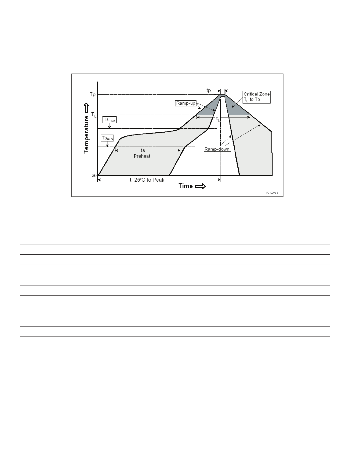
Reflow Soldering Characteristics
JEDEC 020c
Temperature Profile for Table 8.
Table 8.
Profile Feature Lead Free Assembly
Average Ramp-Up Rate (Ts
Preheat Temperature Min (Ts
Preheat Temperature Max (Ts
Preheat Time (ts
min
Temperature (TL) 217°C
Time Maintained Above Temperature (TL) 60 - 150 seconds
Peak / Classification Temperature (TP) 260°C
Time Within 5°C of Actual Peak Temperature (tP) 20 - 40 seconds
Ramp - Down Rate 6°C / second max
Time 25°C to Peak Temperature 8 minutes max
to Tp) 3°C / second max
max
) 150°C
min
) 200°C
max
to ts
) 60 - 180 seconds
max
Notes for Table 8:
- All temperatures refer to the application Printed Circuit Board (PCB), measured on the surface adjacent to the package body.
- For additional information on thermal measurement guidelines please refer to Application Brief AB33.
LUXEON Rebel ES Datasheet DS61 20110511 8
Page 9

Mechanical Dimensions
Figure 1. Package outline drawing.
Notes for Figure 1:
- Do not handle the device by the lens—care must be taken to avoid damage to the lens or the interior of the device that can be damaged by
excessive force to the lens.
- Drawings not to scale.
- All dimensions are in millimeters.
- The thermal pad is electrically isolated from the anode and cathode contact pads.
LUXEON Rebel ES Datasheet DS61 20110511 9
Page 10

Pad Configuration
PAD
3
1 2
TOP
Note for Figure 2:
- The Thermal Pad is electrically isolated from the Anode and Cathode contact pads.
3
2 1
BOTTOM
Figure 2. Pad configuration.
Solder Pad Design
1
2
3
FUNCTION
CATHODE
ANODE
THERMAL
Figure 3. Solder pad layout.
Note for Figure 3:
- The photograph shows the recommended LUXEON Rebel ES layout on Printed Circuit Board (PCB). This design easily achieves
a thermal resistance of 7K/W.
- Application Brief AB32 provides extensive details for this layout. Printed Circuit Board layout files (.dwg) are available at
www.philipslumileds.com and www.philipslumileds.cn.com.
LUXEON Rebel ES Datasheet DS61 20110511 10
Page 11

Relative Spectral Distribution vs. Wavelength
Characteristics
LXML-PWN2 (4100K) Neutral-White at Test Current,
Thermal Pad Temperature = 25°C
1
1
1
1
ibution
0.8
0.8
0.8
0.8
0.6
0.6
0.6
pectral Power Distribution
0.4
0.4
0.4
0.2
0.2
Relative Spectral Power Distribution
Relative Spectral Power Distribution
0
0
350 400 450 500 550 600 650 700 750 800
350 400 450 500 550 600 650 700 750 800
Wavelength nm
Figure 4. Color spectrum of LXML-PWN2 emitter, integrated measurement.
LXML-PWC2 (5650K) Cool-White at Test Current,
Thermal Pad Temperature = 25°C
1
1
1
1
0.8
0.8
0.8
0.8
tribution
0.6
0.6
0.6
0.4
0.4
0.4
Spectral Power Distribution
0.2
0.2
Relative Spectral Power Distribution
Relative Spectral Power Distribution
0
0
350 400 450 500 550 600 650 700 750 800
350 400 450 500 550 600 650 700 750 800
Wavelength nm
Figure 5. Color spectrum of LXML-PWC2 emitter, integrated measurement.
LUXEON Rebel ES Datasheet DS61 20110511 11
Page 12

t
e
e
e
1
o
t
a
350
400
450
500
550
600
650
700
750
800
LXW9-PW27 (2700K) at Test Current, Thermal Pad Temperature = 25°C
0.8
n
0.6
Distributi
0.4
ral Power
0.2
tive Spec
Rel
0
Wavelength (nm)
Figure 6. Color spectrum of LXW9-PW27 emitter, integrated measurement.
LXW9-PW30 (3000K) at Test Current, Thermal Pad Temperature = 25°C
1
0.8
ion
0.6
r Distribu
0.4
ctral Pow
0.2
lative Sp
R
0
350 400 450 500 550 600 650 700 750 800
Wavelength (nm)
Figure 7. Color spectrum of LXW9-PW30 emitter, integrated measurement.
LUXEON Rebel ES Datasheet DS61 20110511 12
Page 13

i
c
l
350
400
450
500
550
600
650
700
750
800
o
S
LXW8-PW35 (3500K) at Test Current, Thermal Pad Temperature = 25°C
1
0.8
bution
0.6
wer Distri
0.4
pectral P
0.2
Relative
0
350 400 450 500 550 600 650 700 750 800
Wavelength (nm)
Figure 8. Color spectrum of LXW8-PW35 emitter, integrated measurement.
LXH7-PW40 (4000K) at Test Current, Thermal Pad Temperature = 25°C
1
0.8
on
0.6
r Distribut
0.4
tral Powe
0.2
ative Spe
Re
0
Wavelength (nm)
Figure 9. Color spectrum of LXH7-PW40 emitter, integrated measurement.
LUXEON Rebel ES Datasheet DS61 20110511 13
Page 14

u
w
e
e
r
o
S
LXW8-PW40 (4000K) at Test Current, Thermal Pad Temperature = 25°C
1
0.8
tion
0.6
er Distrib
0.4
ctral Po
0.2
lative Sp
R
0
350 400 450 500 550 600 650 700 750 800
Wavelength (nm)
Figure 10. Color spectrum of LXW8-PW40 emitter, integrated measurement.
LXW8-PW50 (5000K) at Test Current, Thermal Pad Temperature = 25°C
1
0.8
ibution
0.6
wer Dist
0.4
pectral P
0.2
Relative
0
350 400 450 500 550 600 650 700 750 800
Wavelength (nm)
Figure 11. Color spectrum of LXW8-PW50 emitter, integrated measurement.
LUXEON Rebel ES Datasheet DS61 20110511 14
Page 15

Typical Light Output Characteristics
Typical Relative Luminous Flux Vs Temperature for 4100K Neutral-White,
5650K Cool-White, 2700K, 3000K, 3500K, 4000K and 5000K Emitters
at Test Current
1.2
1.2
1.2
1.2
1
1
1
1
lux
0.8
0.8
0.8
0.6
elative Luminous Flux
Relative Luminous Flux
Relative Luminous Flux
0.6
0.6
0.4
0.4
2700K, 3000K, 3500K,
4000K, 4100K, 5000K
4100K Neutral-White
4100K Neutral-White
5650K Cool-White
5650K Cool-White
5650K Cool-White
0.2
0.2
0
0
-20 0 20 40 60 80 100 120 140
Thermal Pad Temperature °C
Figure 12. Relative light output vs. thermal pad temperature.
LUXEON Rebel ES Datasheet DS61 20110511 15
Page 16

Typical Forward Current Characteristics
r
200
0
4100K Neutral-White, 5650K Cool-White, 2700K, 3000K, 3500K,
4000K and 5000K at Test Current, Thermal Pad Temperature = 25°C
1200
1000
800
rent mA
600
rward Cu
400
Fo
2.6 2.7 2.8 2.9 3 3.1 3.2
Forward Voltage V
Figure 13. Forward current vs. forward voltage.
LUXEON Rebel ES Datasheet DS61 20110511 16
Page 17

Typical Luminous Efficacy
m
v
Typical Luminous Efficacy Characteristic vs. Forward Current for 4100K
Neutral-White, 5650K Cool-White, 2700K, 3000K, 3500K, 4000K and
5000K Emitters
1.6
1.4
1.2
1
0.8
0.6
alized Luminous Efficacy
0.4
Nor
0.2
0
0 200 400 600 800 1000 1200
Forward Current mA
Figure 14. Typical luminous efficacy characteristic vs. forward current, thermal pad temperature = 25ºC.
Typical Relative Luminous Flux vs. Forward Current for 4100K NeutralWhite, 5650K Cool-White, 2700K, 3000K, 3500K, 4000K and 5000K
Emitters. Thermal Pad Temperature = 25°C
1.6
1.4
1.2
1
0.8
0.6
e Luminous Flux
0.4
Relati
0.2
0
0 200 400 600 800 1000 1200
Forward Current [mA]
Figure 15. Typical relative luminous flux vs. forward current, thermal pad temperature = 25ºC.
LUXEON Rebel ES Datasheet DS61 20110511 17
Page 18

Typical Relative Luminous Efficacy vs. Temperature
1.2
1.2
1.2
1.2
1
1
1
1
0.8
0.8
0.8
0.6
0.6
0.6
d Luminous Efficacy
0.4
0.4
Normalized Luminous Efficacy
Normalized Luminous Efficacy
0.2
0.2
0
0
-20 0 20 40 60 80 100 120 140
2700K, 3000K, 3500K,
4100K Neutral-White
4100K Neutral-White
4000K, 4100K, 5000K
5650K Cool-White
5650K Cool-White
Thermal Pad Temperature °C
Figure 16. Relative luminous efficacy vs. thermal pad temperature, test current 700 mA.
LUXEON Rebel ES Datasheet DS61 20110511 18
Page 19

Current Derating Curves
Current Derating Curves at 350 mA Forward Current Operation for
4100K Neutral-White, 5650K Cool-White, 2700K, 3000K, 3500K, 4000K
and 5000K Emitters
400
400
400
400
400
350
350
350
350
300
300
300
300
250
250
250
250
Current mA
200
200
200
150
150
150
- Forward Current mA
- Forward Current mA
- Forward Current mA
F
F
F
I
I
I
100
100
100
°
15°C/W
15°C/W
15°C/W
25°C/W
25°C/W
25°C/W
35°C/W
35°C/W
35°C/W
45°C/W
45°C/W
45°C/W
50
50
0
0
0 25 50 75 100 125 150 175
0 25 50 75 100 125 150 175
TA- Ambient Temperature °C
TA- Ambient Temperature °C
Figure 17. Maximum forward current vs. ambient temperature, based on T
JMAX
= 150ºC.
Current Derating Curves at 700mA Forward Current Operation for
4100K Neutral-White, 5650K Cool-White, 2700K, 3000K, 3500K, 4000K
and 5000K Emitters
800
800
800
800
800
700
700
700
700
600
600
600
600
500
500
500
500
urrent mA
15°C/W
15°C/W
400
400
400
300
300
300
- Forward Current mA
- Forward Current mA
- Forward Current mA
F
F
F
I
I
I
200
200
200
15°C/W
25°C/W
25°C/W
25°C/W
35°C/W
35°C/W
35°C/W
100
100
0
0
0 25 50 75 100 125 150 175
0 25 50 75 100 125 150 175
TA- Ambient Temperature °C
TA- Ambient Temperature °C
Figure 18. Maximum forward current vs. ambient temperature, based on T
LUXEON Rebel ES Datasheet DS61 20110511 19
= 150ºC.
JMAX
Page 20

Current Derating Curves at 1000 mA Forward Current Operation for
4100K Neutral-White, 5650K Cool-White, 2700K, 3000K, 3500K, 4000K
and 5000K Emitters
1200
1200
1200
1200
1000
1000
1000
800
800
800
600
rd Current mA
600
600
15°C/W
- Forward Current mA
- Forward Current mA
F
F
I
I
400
400
200
200
0
0 25 50 75 100 125 150 175
15°C/W
25°C/W
25°C/W
TA- Ambient Temperature °C
Figure 19. Maximum forward current vs. ambient temperature, based on T
JMAX
= 150ºC.
LUXEON Rebel ES Datasheet DS61 20110511 20
Page 21

Typical Radiation Patterns
Typical Spatial Radiation Pattern for 4100K Neutral-White,
5650K Cool-White, 2700K, 3000K, 3500K, 4000K and 5000K Emitters
100%
100%
100%
100%
90%
90%
90%
90%
80%
80%
80%
80%
70%
70%
70%
60%
60%
60%
50%
50%
50%
tive Intensity
40%
40%
Relative Intensity
Relative Intensity
30%
30%
20%
20%
10%
10%
0%
-90 -75 -60 -45 -30 -15 0 15 30 45 60 75 90
Angular Displacement (degrees)
Figure 20. Typical representative spatial radiation pattern for 4100K neutral-white,
5650K cool-white, 2700K, 3000K 3500K, 4000K and 5000K lambertian.
LUXEON Rebel ES Datasheet DS61 20110511 21
Page 22

Emitter Pocket Tape Packaging
20
1000
50
LUXEON Rebel ES Datasheet DS61 20110511 22
Page 23

Emitter Reel Packaging
LUXEON Rebel ES Datasheet DS61 20110511 23
Page 24

Product Binning and Labeling
Purpose of Product Binning
In the manufacturing of semiconductor products, there is a variation of performance around the average values given in the technical data sheets.
For this reason, Philips Lumileds bins the LED components for luminous flux, color and forward voltage (Vf ).
Decoding Product Bin Labeling
LUXEON Rebel ES emitters are labeled using a four digit alphanumeric code (CAT code) depicting the bin values for emitters packaged on a single
reel. All emitters packaged within a reel are of the same 3-variable bin combination. Using these codes, it is possible to determine optimum mixing
and matching of products for consistency in a given application.
Reels of LUXEON Rebel ES emitters are labeled with a four digit alphanumeric CAT code following the format below.
ABCD
A = Flux bin (P, Q, R, S etc.)
B and C = Color bin (W0, V0, U0 etc. for LXML-PWx2 series. 7A, 7B, 7C and 7D for LXWx-PWxx series.
5W, 5X, 5Y and 5Z for LXH7-PW40 emitter)
D = Vf bin (P, R, S and T)
LUXEON Rebel ES Datasheet DS61 20110511 24
Page 25

Luminous Flux Bins
Table 9 lists the standard photometric luminous flux bins for LUXEON Rebel ES emitters (tested and binned at 700 mA).
Although several bins are outlined, product availability in a particular bin varies by production run and by product performance.
Not all bins are available in all colors.
Table 9.
Flux Bins
Minimum Photometric Flux Maximum Photometric Flux
Bin Code (lm) (lm)
P 120 140
Q 140 160
R 160
S 180 200
T 200 220
U 220 240
V 240 260
W 260 280
X 280 300
*
170 lm for LXW8-PW40
*
180
LUXEON Rebel ES Datasheet DS61 20110511 25
Page 26

4100K Neutral-White Bin Structure
4100K Neutral-White LUXEON Rebel ES emitters are tested and binned by x,y coordinates. 12 Color Bins, CCT Range 3,500K to 4,500K.
0.44
0.42
4100K
3500K
3800K
RM
0.40
0.38
4500K
TM
TN
y
T0
0.36
TP
0.34
0.32
0.33 0.35 0.37 0.39 0.41 0.43
SP
SM
SN
S0
RN
blackbody locus
R0
RP
x
Figure 21. 4100K Neutral-White bin structure.
Table 10.
4100K Neutral-White Bin Coordinates
Typical CCT Typical CCT
Bin Code X Y (K) Bin Code X Y (K)
0.367294 0.400290 0.378264 0.382458
TM 0.385953 0.412995 4300 S0 0.392368 0.390932 3950
0.381106 0.393747 0.387071 0.373899
0.364212 0.382878 0.374075 0.365822
0.364212 0.382878 0.374075 0.365822
TN 0.381106 0.393747 4300 SP 0.387071 0.373899 3950
0.378264 0.382458 0.382598 0.359515
0.362219 0.371616 0.370582 0.351953
0.362219 0.371616 0.402270 0.422776
T0 0.378264 0.382458 4300 RM 0.420940 0.432618 3650
0.374075 0.365822 0.414776 0.416097
0.359401 0.355699 0.396279 0.403508
0.359401 0.355699 0.396279 0.403508
TP 0.374075 0.365822 4300 RN 0.414776 0.416097 3650
0.370582 0.351953 0.408593 0.399525
0.357079 0.342581 0.392368 0.390932
0.385953 0.412995 0.392368 0.390932
SM 0.402270 0.422776 3950 R0 0.408593 0.399525 3650
0.396279 0.403508 0.402113 0.382156
0.381106 0.393747 0.387071 0.373899
0.381106 0.393747 0.387071 0.373899
SN 0.396279 0.403508 3950 RP 0.402113 0.382156 3650
0.392368 0.390932 0.396564 0.367284
0.378264 0.382458 0.382598 0.359515
Note for Table 10:
- Philips Lumileds maintains a tester tolerence of ± 0.005 on x, y color coordinates.
LUXEON Rebel ES Datasheet DS61 20110511 26
Page 27

5650K Cool-White Bin Structure
0.41
0.39
5000K
4500K
UM
5650K
0.37
6300K
X0
WM
WN
W0
WP
WQ
XP
0.35
7000K
XM
0.33
XN
y
0.31
0.29
0.27
10000K
Y0
YA
VM
VN
V0
VP
UP
U0
UN
blackbody locus
0.25
0.25
0.27 0.29 0.31 0.33 0.35 0.37 0.39
x
Figure 22. 5650K Cool-White bin structure.
LUXEON Rebel ES Datasheet DS61 20110511 27
Page 28

5650K Cool-White LUXEON Rebel ES emitters are tested and binned by x,y coordinates. 19 Color Bins, CCT Range 4,500K to 10,000K.
Table 11.
5650K Cool-White Bin Coordinates
Typical CCT Typical CCT
Bin Code X Y (K) Bin Code X Y (K)
0.274238 0.300667 0.318606 0.310201
Y0 0.303051 0.332708 8000 WQ 0.329393 0.320211 6000
0.307553 0.310778 0.329544 0.310495
0.282968 0.283772 0.319597 0.301303
0.282968 0.283772 0.328636 0.368952
YA 0.307553 0.310778 8000 VM 0.348147 0.385629 5300
0.311163 0.293192 0.346904 0.371742
0.289922 0.270316 0.328823 0.356917
0.301093 0.342244 0.328823 0.356917
XM 0.313617 0.354992 6700 VN 0.346904 0.371742 5300
0.314792 0.344438 0.345781 0.359190
0.303051 0.332708 0.329006 0.345092
0.303051 0.332708 0.329006 0.345092
XN 0.314792 0.344438 6700 V0 0.345781 0.359190 5300
0.316042 0.333222 0.344443 0.344232
0.305170 0.322386 0.329220 0.331331
0.305170 0.322386 0.329220 0.331331
X0 0.316042 0.333222 6700 VP 0.344443 0.344232 5300
0.317466 0.320438 0.343352 0.332034
0.307553 0.310778 0.329393 0.320211
0.307553 0.310778 0.348147 0.385629
XP 0.317466 0.320438 6700 UM 0.367294 0.400290 4750
0.319597 0.301303 0.364212 0.382878
0.311163 0.293192 0.346904 0.371742
0.313617 0.354992 0.346904 0.371742
WM 0.328636 0.368952 6000 UN 0.364212 0.382878 4750
0.328823 0.356917 0.362219 0.371616
0.314792 0.344438 0.345781 0.359190
0.314792 0.344438 0.345781 0.359190
WN 0.328823 0.356917 6000 U0 0.362219 0.371616 4750
0.329006 0.345092 0.359401 0.355699
0.316042 0.333222 0.344443 0.344232
0.316042 0.333222 0.344443 0.344232
W0 0.329006 0.345092 6000 UP 0.359401 0.355699 4750
0.329220 0.331331 0.357079 0.342581
0.317466 0.320438 0.343352 0.332034
0.317466 0.320438
WP 0.329220 0.331331 6000
0.329393 0.320211
0.318606 0.310201
Note for Table 11:
- Philips Lumileds maintains a tester tolerence of ± 0.005 on x, y color coordinates.
LUXEON Rebel ES Datasheet DS61 20110511 28
Page 29

LUXEON Rebel ES ANSI 1/4th Quadrant Color
Bin Structure
ANSI 1/4th quadrant color bin structure for LXW9-PW27, LXW9-PW30,
LXW8-PW35, LXW8-PW40 and LXW8-PW50 emitters
Figure 23. LUXEON Rebel ES ANSI 1/4th quadrant color bin structure.
LUXEON Rebel ES Datasheet DS61 20110511 29
Page 30

LUXEON Rebel ES ANSI 1/4th Quadrant
Bin Coordinates, Continued
LUXEON Rebel ES emitters are tested and binned by x,y coordinates.
32 Color Bins, CCT Range 2580K to 7040K
Table 12.
LUXEON Rebel ES ANSI 1/4th quadrant Bin Coordinates
Nominal CCT Bin Code x y Nominal CCT Bin Code x y
0.458614 0.410315 0.408216 0.392153
8A 0.446470 0.407117 6A 0.394131 0.384815
0.437300 0.389300 0.388900 0.369000
0.448286 0.391847 0.401706 0.375155
0.468732 0.428946 0.414622 0.408937
8B 0.456200 0.426000 6B 0.399600 0.401500
0.446470 0.407117 0.394131 0.384815
0.458614 0.410315 0.408216 0.392153
2700K
0.481300 0.431900 0.429900 0.416500
8C 0.468732 0.428946 6C 0.414622 0.408937
0.458614 0.410315 0.408216 0.392153
0.469954 0.412602 0.422071 0.398417
0.469954 0.412602 0.422071 0.398417
8D 0.458614 0.410315 6D 0.408216 0.392153
0.448286 0.391847 0.401706 0.375155
0.459300 0.394400 0.414700 0.381400
0.434392 0.403186 0.381883 0.377641
7A 0.422071 0.398417 5A 0.369655 0.369740
0.414700 0.381400 0.367000 0.357800
0.425959 0.385336 0.378297 0.364637
0.442994 0.421230 0.386955 0.395809
7B 0.429900 0.416500 5B 0.373600 0.387400
0.422071 0.398417 0.369655 0.369740
0.434392 0.403186 0.381883 0.377641
3000K
0.456200 0.426000 0.400600 0.404400
7C 0.442994 0.421230 5C 0.386955 0.395809
0.434392 0.403186 0.381883 0.377641
0.446470 0.407117 0.394131 0.384815
0.446470 0.407117 0.394131 0.384815
7D 0.434392 0.403186 5D 0.381883 0.377641
0.425959 0.385336 0.378297 0.364637
0.437300 0.389300 0.389800 0.371600
3500K
4000K
LUXEON Rebel ES Datasheet DS61 20110511 30
Page 31

LUXEON Rebel ES ANSI 1/4th Quadrant
Bin Coordinates, Continued
LUXEON Rebel ES emitters are tested and binned by x,y coordinates.
32 Color Bins, CCT Range 2580K to 7040K
Table 12, Continued.
LUXEON Rebel ES ANSI 1/4th quadrant color bin coordinates
Nominal CCT Bin Code x y
0.344719 0.351301
3A 0.336916 0.344873
0.336600 0.336900
0.343985 0.342749
0.346260 0.368726
3B 0.337600 0.361600
0.336916 0.344873
0.344719 0.351301
5000K
0.355100 0.376000
3C 0.346260 0.368726
0.344719 0.351301
0.352638 0.357500
0.352638 0.357500
3D 0.344719 0.351301
0.343985 0.342749
0.351500 0.348700
Notes for Table 12:
- Philips Lumileds maintains a tester tolerence of ± 0.005 on x, y color coordinates.
- Applicable for LXW9-PW27, LXW9-PW30, LXW8-PW35, LXW8-PW40 and LXW8-PW50 emitters.
LUXEON Rebel ES Datasheet DS61 20110511 31
Page 32

LUXEON Rebel ES ANSI 1/4th Quadrant
Bin Structure
ANSI 1/4th quadrant bin structure for LXH7-PW40 emitter
0.41
0.40
4000K
0.39
5X
0.38
y
5Z
0.37
0.36
0.35
0.35 0.37 0.38 0.39 0.40 0.410.36 0.42
5W
3985K
±275K
5Y
blackbody locus
x
Figure 24. LUXEON Rebel ES ANSI 1/4th quadrant bin structure (LXH7-PW40 emitter only).
LUXEON Rebel ES Datasheet DS61 20110511 32
Page 33

LUXEON Rebel ES ANSI 1/4th Quadrant
Bin Coordinates for LXH7-PW40 emitter
LUXEON Rebel ES emitters are tested and binned by x,y coordinates.
4 Color Bins, CCT Range 3710K to 4260K
Table 13.
LUXEON Rebel ES ANSI 1/4th quadrant Bin Coordinates for LXH7-PW40 emitter
Nominal CCT Bin Code x y
0.382750 0.380300
5W 0.370300 0.372600
0.367000 0.357800
0.378400 0.364700
0.382750 0.380300
5X 0.387100 0.395900
0.373600 0.387400
0.370300 0.372600
0.382750 0.380300
5Y 0.395200 0.388000
0.400600 0.404400
0.387100 0.395900
0.382750 0.380300
5Z 0.378400 0.364700
0.389800 0.371600
0.395200 0.388000
4000K
LUXEON Rebel ES Datasheet DS61 20110511 33
Page 34

Forward Voltage Bins
Table 14 lists minimum and maximum Vf bin values per emitter (tested and binned at 700 mA). Although several bins are outlined, product availability
in a particular bin varies by production run and by product performance.
Table 14.
Vf Bins
Minimum Forward Voltage Maximum Forward Voltage
Bin Code (V) (V)
P 2.50 2.75
R 2.75 3.00
S 3.00 3.25
T 3.25 3.50
LUXEON Rebel ES Datasheet DS61 20110511 34
Page 35

Company Information
Philips Lumileds is a leading provider of power LEDs for everyday lighting applications. The company’s records for light output,
efficacy and thermal management are direct results of the ongoing commitment to advancing solid-state lighting technology
and enabling lighting solutions that are more environmentally friendly, help reduce CO
power plant expansion. Philips Lumileds LUXEON
®
LEDs are enabling never before possible applications in outdoor lighting,
emissions and reduce the need for
2
shop lighting, home lighting, digital imaging, display and automotive lighting.
Philips Lumileds is a fully integrated supplier, producing core LED material in all three base colors, (red, green, blue) and
white. Philips Lumileds has R&D centers in San Jose, California and in the Netherlands, and production capabilities in
San Jose, Singapore and Penang, Malaysia. Founded in 1999, Philips Lumileds is the high flux LED technology leader and is
dedicated to bridging the gap between solid-state technology and the lighting world. More information about the company’s
LUXEON LED products and solid-state lighting technologies can be found at www.philipslumileds.com.
©2011 Philips Lumileds Lighting Company. All rights reserved.
Product specifications are subject to change without notice.
LUXEON is a registered trademark of the Philips Lumileds
Lighting Company in the United States and other countries.
www.philipslumileds.com
www.philipslumileds.cn.com
www.futurelightingsolutions.com
For technical assistance or the
location of your nearest sales
office contact any of the
following:
North America:
1 888 589 3662
americas@futurelightingsolutions.com
Europe:
00 800 443 88 873
europe@futurelightingsolutions.com
Asia Pacific:
800 5864 5337
asia@futurelightingsolutions.com
Japan:
800 5864 5337
japan@futurelightingsolutions.com
 Loading...