

Page 1
Instructions for Use
English
DigitalDiagnost C90
Version 1.1
4512 987 46122 AA/712 * MAR 2020 - en-US
Page 2

DigitalDiagnost C90
Version 1.1
DigitalDiagnost C90
Version 1.1
4512 987 46122 AA - en-US
4512 987 46122 AA - en-US
DigitalDiagnost C90
Version 1.1
4512 987 46122 AA - en-US
Page 3

DigitalDiagnost C90
Version 1.1
DigitalDiagnost C90
Version 1.1
4512 987 46122 AA - en-US
4512 987 46122 AA - en-US
DigitalDiagnost C90
Version 1.1
DigitalDiagnost C90
Version 1.1
4512 987 46122 AA - en-US
4512 987 46122 AA - en-US
DigitalDiagnost C90
Version 1.1
4512 987 46122 AA - en-US
Page 4

Contents of this folder
InstructionsforUse
DigitalDiagnostC90V.1.1
ElevaWorkspotforDigitalDiagnostC90V.1.1
Philips
DigitalDiagnostC90V.1.1 451298746122AA/712/2020‐03
Page 5

DigitalDiagnost C90
Instructions for Use
Version 1.1
Philips 4512 987 46122 AA/712 * MAR 2020
Page 6

www.philips.com/healthcare
Philips Medical Systems DMC GmbH
Röntgenstraße 24
22335 Hamburg
Germany
0123
© 2020 Koninklijke Philips N.V.
All rights are reserved. Reproduction or transmission in whole or in part, in any form or by any means, electronic, mechanical or otherwise, is prohibited without the prior written consent of the copyright owner.
Printed in Germany
4512 987 46122 AA/712 * MAR 2020 - en-US
Page 7

Table of contents
Table of contents
1 Worth Knowing...................................................................................................................................... 11
Publication Details.......................................................................................................................................... 11
Compliance..................................................................................................................................................... 11
About These Instructions for Use................................................................................................................... 12
Intended Use................................................................................................................................................... 13
Indications for Use.......................................................................................................................................... 13
Intended Operator Profile.............................................................................................................................. 13
Contraindications............................................................................................................................................ 14
Target Population........................................................................................................................................... 14
Clinical Benefits............................................................................................................................................... 15
Prohibited Use................................................................................................................................................ 15
Compatibility................................................................................................................................................... 16
Prescription Device Statement....................................................................................................................... 16
Training........................................................................................................................................................... 16
Conformity...................................................................................................................................................... 17
Dangerous Substances....................................................................................................................... 17
Mercury (USA Only)........................................................................................................................... 17
Perchlorate........................................................................................................................................ 17
Reader Manufacturer's Address..................................................................................................................... 17
2 Safety and Requirements........................................................................................................................ 19
Warnings and Cautions................................................................................................................................... 19
Electrical Safety............................................................................................................................................... 21
Mechanical Safety........................................................................................................................................... 23
Special Mechanical Safety............................................................................................................................... 24
Explosion Safety.............................................................................................................................................. 27
Fire Safety....................................................................................................................................................... 28
Damage as a Result of Incorrect Cassette Insertion....................................................................................... 28
Electrostatic Discharge (ESD).......................................................................................................................... 28
Electromagnetic Compatibility........................................................................................................................ 29
Radiation Protection....................................................................................................................................... 32
Radiation Dose Management......................................................................................................................... 33
Laser Light Source........................................................................................................................................... 37
In the Event of Power Outage......................................................................................................................... 37
Error Messages............................................................................................................................................... 37
Philips 4512 987 46122 AA/712 * MAR 2020
DigitalDiagnost C90 Version 1.1 3
Page 8

Table of contents
At the Geometry................................................................................................................................ 37
At the Eleva Workspot....................................................................................................................... 38
At the UPS (Optional)........................................................................................................................ 40
3 System Description................................................................................................................................. 43
System............................................................................................................................................................. 43
System Components....................................................................................................................................... 44
Eleva Workspot.................................................................................................................................. 44
UPS for Eleva Workspot (Optional).................................................................................................... 45
Ceiling Suspension CSM3................................................................................................................... 49
Remote Control for the Ceiling Suspension CSM3............................................................................ 50
Eleva Tube Head................................................................................................................................ 53
Display of the Eleva Tube Head......................................................................................................... 55
Vertical Stand 2.................................................................................................................................. 57
DigitalDiagnost VM............................................................................................................................ 64
DigitalDiagnost TH2........................................................................................................................... 70
Single-Sided Table TH-S..................................................................................................................... 73
Fixed Detector................................................................................................................................... 75
SkyPlate Detector.............................................................................................................................. 76
PCR S Plus Cassette Reader............................................................................................................... 86
4 Switching the System On/Off.................................................................................................................. 91
Switching On................................................................................................................................................... 91
Logging In........................................................................................................................................................ 92
Quick Logout................................................................................................................................................... 93
Switching Off................................................................................................................................................... 94
Aborting the System....................................................................................................................................... 94
Restarting the System..................................................................................................................................... 95
Emergency Access to the System.................................................................................................................... 95
The PCR S Plus Plate Reader........................................................................................................................... 97
UPS for Eleva Workspot (Optional)............................................................................................................... 100
Installation....................................................................................................................................... 100
Switching the System Off (Only for Service Reasons)...................................................................... 100
Switching the System On................................................................................................................. 101
In the Event of a Power Outage....................................................................................................... 102
5 Operation............................................................................................................................................. 103
Safety Awareness.......................................................................................................................................... 103
Workflow...................................................................................................................................................... 103
Quick Way to Great Exposures........................................................................................................ 103
If You Do not Follow the Usual Workflow....................................................................................... 104
System Components..................................................................................................................................... 104
Ceiling Suspension CSM3................................................................................................................. 104
4 DigitalDiagnost C90 Version 1.1
Philips 4512 987 46122 AA/712 * MAR 2020
Page 9

Table of contents
Vertical Stand 2................................................................................................................................ 131
DigitalDiagnost VM.......................................................................................................................... 137
DigitalDiagnost TH2......................................................................................................................... 145
Single-Sided Table TH-S................................................................................................................... 151
Fixed Detector................................................................................................................................. 156
SkyPlate Detector............................................................................................................................ 163
PCR S Plus Plate Reader................................................................................................................... 212
Examinations................................................................................................................................................. 222
Stitching (Optional).......................................................................................................................... 222
Preparation at the Eleva Workspot................................................................................................. 222
Positioning the System and the Patient........................................................................................... 223
Releasing an Exposure..................................................................................................................... 227
Postprocessing at the Eleva Workspot............................................................................................ 229
6 Functions.............................................................................................................................................. 231
Defined Exposure Positions.......................................................................................................................... 231
PCR Integration............................................................................................................................................. 231
7 Maintenance, Cleaning, and Disposal.................................................................................................... 233
Maintenance................................................................................................................................................. 233
Planned Maintenance...................................................................................................................... 233
Repairs............................................................................................................................................. 233
Recording Results............................................................................................................................ 234
User Routine Checks..................................................................................................................................... 234
Obligations of the User.................................................................................................................... 234
Tests and Checks by the User.......................................................................................................... 234
Safety Checks According to the Medical Device Directive............................................................... 235
Checking the AEC Function.............................................................................................................. 236
Checking the Dose Area Product Indication.................................................................................... 237
Performance Check of the Automatic Collimator............................................................................ 237
Cleaning and Disinfecting.............................................................................................................................. 238
Rules and Instructions..................................................................................................................... 238
Types of Disinfectants...................................................................................................................... 241
Restrictions for Certain Types of Disinfectants................................................................................ 244
Special Instructions for Certain Components.................................................................................. 245
Product Disposal........................................................................................................................................... 253
Passing the Product on to Another User....................................................................................................... 254
REACH Requirements.................................................................................................................................... 255
8 Technical Data...................................................................................................................................... 257
System.......................................................................................................................................................... 257
Ambient Conditions......................................................................................................................... 257
Eleva Workspot............................................................................................................................................. 257
Generator...................................................................................................................................................... 257
Philips 4512 987 46122 AA/712 * MAR 2020
DigitalDiagnost C90 Version 1.1 5
Page 10

Table of contents
Electrical Data.................................................................................................................................. 257
Exposure Techniques....................................................................................................................... 258
AEC Supervision (Fail Safe AEC)....................................................................................................... 258
Setting Ranges................................................................................................................................. 259
Ambient Conditions......................................................................................................................... 259
Accuracy of the Operating Data, Tolerances................................................................................... 260
X-ray Tube Compatibility................................................................................................................. 261
Methods of Measurement.............................................................................................................. 261
Labels............................................................................................................................................... 262
Ceiling Suspension CSM3.............................................................................................................................. 262
Equipment Data............................................................................................................................... 262
Compatibility................................................................................................................................... 263
Labels............................................................................................................................................... 265
Vertical Stand 2............................................................................................................................................. 267
Equipment Data............................................................................................................................... 267
Compatibility................................................................................................................................... 267
Options............................................................................................................................................ 267
Labels Vertical Stand 2..................................................................................................................... 268
DigitalDiagnost VM....................................................................................................................................... 269
Equipment Data............................................................................................................................... 269
Compatibility................................................................................................................................... 270
Labels............................................................................................................................................... 270
DigitalDiagnost TH2...................................................................................................................................... 272
Equipment Data............................................................................................................................... 272
Compatibility................................................................................................................................... 272
Labels............................................................................................................................................... 273
Single Sided Table TH-S................................................................................................................................. 274
Equipment Data............................................................................................................................... 274
Compatibility................................................................................................................................... 274
Labels............................................................................................................................................... 276
Fixed Detector............................................................................................................................................... 276
SkyPlate Detector......................................................................................................................................... 277
Ambient Conditions......................................................................................................................... 277
Equipment Data............................................................................................................................... 277
Small SkyPlate in Incubator............................................................................................................. 279
Labels............................................................................................................................................... 280
Typical IQ Performance................................................................................................................................. 285
Ambient Conditions of the Measuring Chamber.......................................................................................... 285
Grids for the Bucky Unit................................................................................................................................ 286
Changeable Grids and Usable SIDs for the Bucky Unit.................................................................... 286
Grids for the SkyPlate................................................................................................................................... 288
Changeable Grid Frames and Usable SIDs....................................................................................... 288
Technical Data................................................................................................................................. 289
6 DigitalDiagnost C90 Version 1.1
Philips 4512 987 46122 AA/712 * MAR 2020
Page 11

Table of contents
Patient Dose Calculation............................................................................................................................... 289
Electromagnetic Compatibility (EMC) Data.................................................................................................. 290
Guidance and Manufacturer’s Declaration..................................................................................... 290
WiFi.................................................................................................................................................. 294
PCR S Plus Cassette Reader........................................................................................................................... 295
Equipment Data............................................................................................................................... 295
Ambient Conditions......................................................................................................................... 297
Labels............................................................................................................................................... 298
9 Accessories........................................................................................................................................... 299
For Your Safety.............................................................................................................................................. 299
Parking Frame for Accessories...................................................................................................................... 299
Hand Grips.................................................................................................................................................... 300
Normal Use...................................................................................................................................... 300
Legend............................................................................................................................................. 300
Installing.......................................................................................................................................... 301
Dismantling...................................................................................................................................... 301
Compatibility................................................................................................................................... 301
Technical Data................................................................................................................................. 302
Labels............................................................................................................................................... 302
Lead Apron for Vertical Stand 2.................................................................................................................... 302
Normal Use...................................................................................................................................... 302
Prohibited Use................................................................................................................................. 302
Legend............................................................................................................................................. 303
Operation........................................................................................................................................ 303
Compatibility................................................................................................................................... 304
Labels............................................................................................................................................... 304
Side Bar......................................................................................................................................................... 304
Normal Use...................................................................................................................................... 304
Prohibited Use................................................................................................................................. 305
Legend............................................................................................................................................. 305
Installing.......................................................................................................................................... 305
Dismantling...................................................................................................................................... 306
Technical Data................................................................................................................................. 307
Compatibility................................................................................................................................... 307
Labels............................................................................................................................................... 307
Adjustable Straps.......................................................................................................................................... 307
Normal Use...................................................................................................................................... 307
Prohibited Use................................................................................................................................. 307
Legend............................................................................................................................................. 308
Installing.......................................................................................................................................... 308
Dismantling...................................................................................................................................... 309
Operation........................................................................................................................................ 309
Detaching the Belt........................................................................................................................... 309
Philips 4512 987 46122 AA/712 * MAR 2020
Attaching the Belt............................................................................................................................ 310
DigitalDiagnost C90 Version 1.1 7
Page 12

Table of contents
Technical Data................................................................................................................................. 310
Compatibility................................................................................................................................... 310
Labels............................................................................................................................................... 311
Compression Belt.......................................................................................................................................... 311
Safety Instructions........................................................................................................................... 311
Normal Use...................................................................................................................................... 311
Installing.......................................................................................................................................... 311
Dismantling...................................................................................................................................... 313
Compatibility................................................................................................................................... 313
Technical Data................................................................................................................................. 313
Labels............................................................................................................................................... 314
Infusion Bottle Holder................................................................................................................................... 314
Normal Use...................................................................................................................................... 314
Prohibited Use................................................................................................................................. 314
Legend............................................................................................................................................. 315
Installing.......................................................................................................................................... 315
Dismantling...................................................................................................................................... 316
Technical Data................................................................................................................................. 316
Compatibility................................................................................................................................... 316
Labels............................................................................................................................................... 316
Paper Roll Holder.......................................................................................................................................... 317
Normal Use...................................................................................................................................... 317
Prohibited Use................................................................................................................................. 317
Legend............................................................................................................................................. 317
Installing.......................................................................................................................................... 318
Dismantling...................................................................................................................................... 319
Technical Data................................................................................................................................. 320
Compatibility................................................................................................................................... 320
Labels............................................................................................................................................... 320
Support for CPR (Cardio Pulmonary Resuscitation)...................................................................................... 320
Normal Use...................................................................................................................................... 320
Prohibited Use................................................................................................................................. 321
Legend............................................................................................................................................. 321
Operation........................................................................................................................................ 321
Technical Data................................................................................................................................. 322
Compatibility................................................................................................................................... 322
Labels............................................................................................................................................... 322
Babix Holder.................................................................................................................................................. 322
Normal Use...................................................................................................................................... 322
Prohibited Use................................................................................................................................. 322
Legend............................................................................................................................................. 323
Installing.......................................................................................................................................... 323
Operating......................................................................................................................................... 323
Technical Data................................................................................................................................. 324
Labels............................................................................................................................................... 324
Philips 4512 987 46122 AA/712 * MAR 2020
8 DigitalDiagnost C90 Version 1.1
Page 13

Table of contents
Stretch Grip................................................................................................................................................... 325
Normal Use...................................................................................................................................... 325
Prohibited Use................................................................................................................................. 325
Installing/Dismantling...................................................................................................................... 325
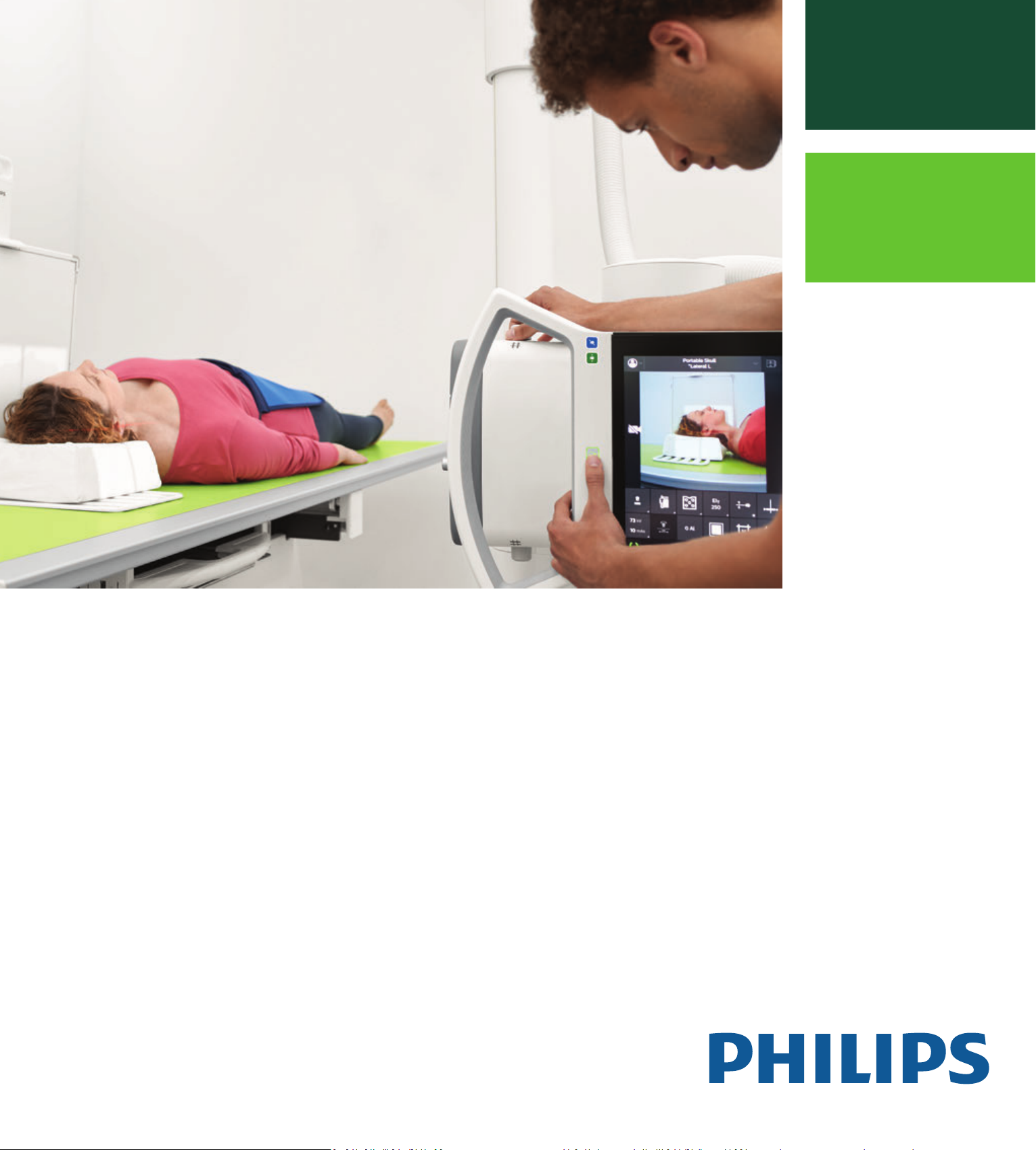
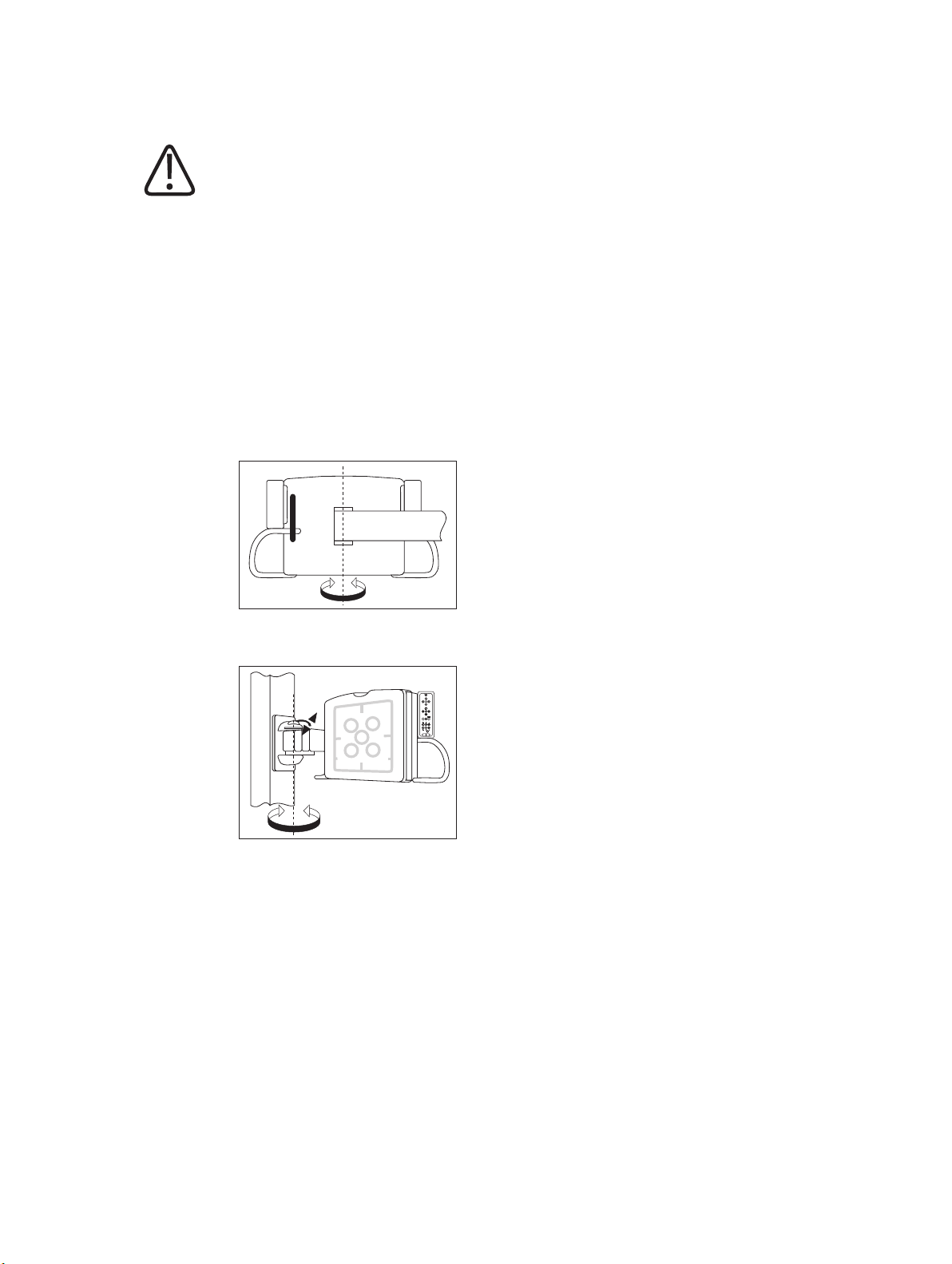
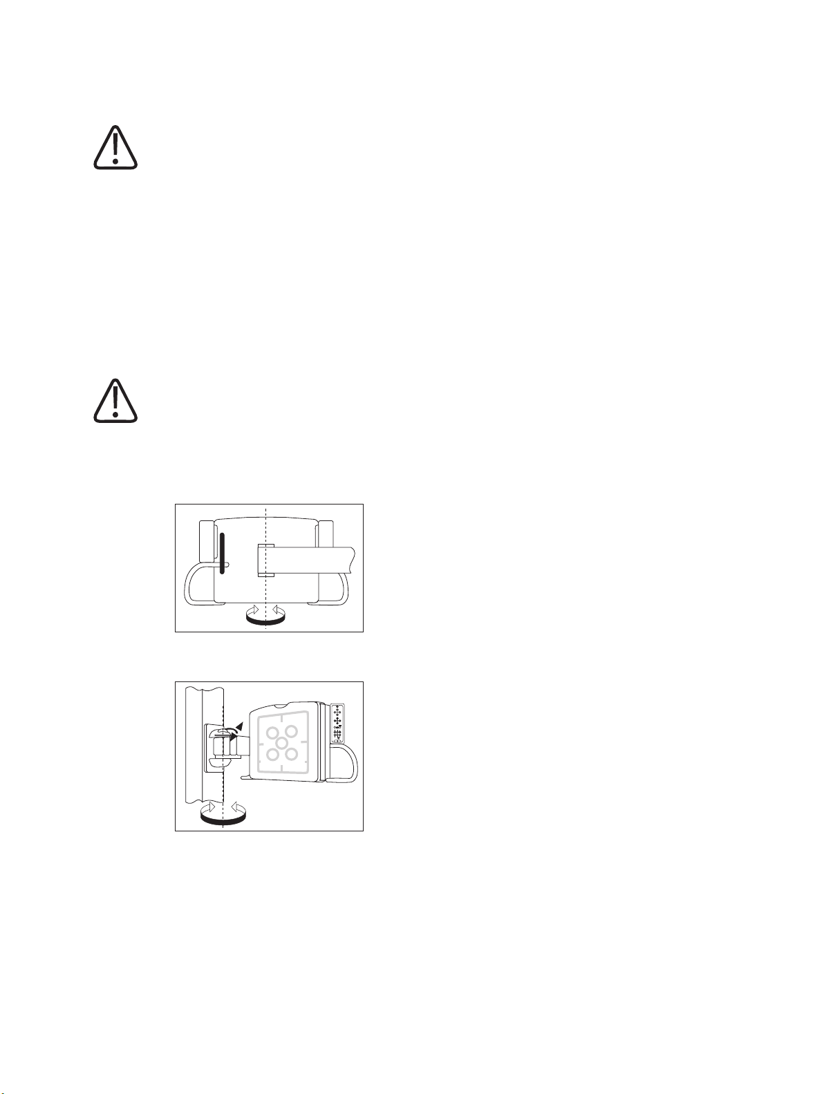
Swiveling the Stretch Grip............................................................................................................... 326
Technical Data................................................................................................................................. 327
Compatibility................................................................................................................................... 327
Labels............................................................................................................................................... 327
Accessories for the SkyPlate Detector.......................................................................................................... 328
Detector Handle.............................................................................................................................. 328
Mobile Detector Holder................................................................................................................... 331
Detector Holder Patient Bed........................................................................................................... 338
Portable Panel Protector................................................................................................................. 346
WPD Hygienic Bags.......................................................................................................................... 348
10 Appendix.............................................................................................................................................. 351
Messages at the Eleva Tube Head................................................................................................................ 351
Messages at the UPS (Optional)................................................................................................................... 366
Prompts........................................................................................................................................... 366
Warnings.......................................................................................................................................... 367
Faults............................................................................................................................................... 367
Troubleshooting UPS Issues.......................................................................................................................... 369
List of Symbols.............................................................................................................................................. 371
Glossary........................................................................................................................................................ 375
Index.................................................................................................................................................... 377
Philips 4512 987 46122 AA/712 * MAR 2020
DigitalDiagnost C90 Version 1.1 9
Page 14

Table of contents
10 DigitalDiagnost C90 Version 1.1
Philips 4512 987 46122 AA/712 * MAR 2020
Page 15

Publication Details Worth Knowing
0123
Worth Knowing
1
Publication Details
Published by Philips Medical Systems DMC GmbH
Philips Medical Systems DMC GmbH reserves the right to make changes to both these Instructions for Use and to the product they describe. Product specifications are subject to change
without notice. Nothing contained within these Instructions for Use is intended as any offer,
warranty, promise or contractual condition, and must not be taken as such.
Compliance
This Medical Device meets the provisions of the European Medical Device Regulations.
The wireless portable detector meets the provisions of the Radio Equipment Directive
2014/53/EU.
This Medical Device complies with the following standards:
• IEC 62304 Medical device software – Software life cycle processes
• IEC 62366 Application of usability engineering to medical devices
• ISO 14971 Application of risk management to medical devices
• IEC 60601-1 Medical Electrical Equipment – Part 1: General Requirements For Basic Safety
And Essential Performance
• IEC 60601-1-2 Medical Electrical Equipment - Part 1–2: General Requirements For Basic
Safety And Essential Performance – Collateral Standard: Electromagnetic Compatibility - Requirements And Tests
• IEC 60601-1-3 Medical Electrical Equipment – Part 1–3: General Requirements For Basic
Safety And Essential Performance – Collateral Standard: Radiation Protection In Diagnostic
X-Ray Equipment
• IEC 60601-1-6 Medical Electrical Equipment – Part 1–6: General Requirements For Basic
Safety And Essential Performance – Collateral Standard: Usability
• IEC 60601-2-54 Medical Electrical Equipment – Part 2–54: Particular Requirements For The
Basic Safety And Essential Performance Of X-Ray Equipment For Radiography And Radioscopy
• NEMA PS 3.1 - 3.20 Digital Imaging And Communications In Medicine (DICOM) Set
• ISO 10993-1 Biological Evaluation Of Medical Devices – Part 1: Evaluation And Testing Within A Risk Management Process
If you have further questions regarding the applicable national or international standards,
please address them to:
Philips 4512 987 46122 AA/712 * MAR 2020
DigitalDiagnost C90 Version 1.1 11
Page 16

Worth Knowing About These Instructions for Use
Philips Medical Systems DMC GmbH
Quality Department
Röntgenstraße 24
22335 Hamburg
Germany
About These Instructions for Use
These Instructions for Use are intended to assist users in the safe and effective operation of the
product described. Before attempting to operate the product, you must read these Instructions
for Use, noting and strictly observing all WARNING and CAUTION notices. Pay special attention
to all the information given and procedures described in the “Safety” section.
These Instructions for Use are part of the system. They shall be kept in the immediate vicinity of
the system so that they are accessible at any time.
WARNING
A WARNING alerts you to a potential serious outcome, adverse event or safety hazard. Fail‐
ure to observe a warning may result in death or serious injury to the user or patient.
CAUTION
A CAUTION alerts you to where special care is necessary for the safe and effective use of the
product. Failure to observe a caution may result in minor or moderate personal injury or
damage to the product or other property, and possibly in a remote risk of more serious in‐
jury, and/or cause environmental pollution.
NOTICE
A NOTICE is used to identify special advice, for example to assist the operator or to improve an
operating sequence.
Condition for operation
⊳
► Single step in an action
⇨ Result produced by a step
These Instructions for Use describe the most extensive configuration of the product, with the
maximum number of options and accessories. Not every function described may be available
on your product.
12 DigitalDiagnost C90 Version 1.1
Philips 4512 987 46122 AA/712 * MAR 2020
Page 17

Intended Use Worth Knowing
Depending on the configuration, other Instructions for Use may be delivered with the system,
and these should be consulted for safety instructions, calibration, test procedures and maintenance.
For installation, see the system's service documentation.
These Instructions for Use were originally drafted, approved and supplied by Philips in the English language.
Intended Use
The DigitalDiagnost C90 is intended to acquire, process, store, display and export digital radiographic images. The DigitalDiagnost C90 is suitable for all routine radiography examinations, including specialist areas like intensive care, trauma or pediatric work, excluding fluoroscopy, angiography and mammography.
Indications for Use
The system is suitable for all routine radiographic examinations, including specialist areas such
as intensive care, trauma, or pediatric work. Also advanced applications such as Bone Suppression shall be performed with the system.
Standard radiography procedures are, for example:
• X-ray examinations of the skeleton including skull, chest, spine, pelvis, upper extremities,
lower extremities, etc.
• X-ray examinations of the lungs
• X-ray examinations of soft tissue such as abdomen
• Overview image of the whole spine in vertical and horizontal patient position
• Overview image of the complete leg in vertical and horizontal patient position
The user has the following exposure techniques available:
• Detector exposure with a vertical, horizontal and/or oblique radiation beam
• Free exposure technique for free SkyPlate detector
• Free exposure technique for CR systems of Philips or other vendors and film cassettes
• Manual exposure techniques: kV-mA-ms; kV-mAs; kV-mAs-ms
• Automatic exposure technique: AEC-kV-mA, AEC-kV with falling load
Intended Operator Profile
The system is used with different configurations. It is to be operated by radiographers (technologists). In some cases or countries it is to be operated by especially trained nurses or doctors
when no radiographer is available. Radiographers mostly schedule, prepare, perform, and final-
Philips 4512 987 46122 AA/712 * MAR 2020
DigitalDiagnost C90 Version 1.1 13
Page 18

Worth Knowing Contraindications
ize X-ray examinations and are responsible for the administrative work as well. The operator
must be able to physically operate the system. This includes sufficient capabilities in hearing,
vision, and mobility.
Minimum skills:
• Knowledge in westernized Arabic numerals
• Knowledge in general radiographic positioning and procedures
• Knowledge in anatomy
• Knowledge in radiation protection
• Knowledge in hygiene and basic infection control
The detailed qualifications required to operate an X-ray system are defined by local legal regulations.
Contraindications
No absolute contraindications are given for standard radiology. Due to the nature of X-ray procedures, the patient is exposed to radiation. Adverse health effects exist and are well known.
Therefore, the responsible radiologist must assess risks and benefits. The radiologist must identify relative contraindications, depending, for example, on available alternative diagnosis technologies.
Target Population
The DigitalDiagnost system is intended to support examinations on any kind of patient group
(all patients that enter the facility). Patients might be handicapped, immobile or frightened.
There are situations when it is indicated to avoid any unnecessary movement of the patient (for
example, multiple traumas). Typically, the patients are ill or suspected to be ill.
Patients can be:
• Very young or very old (from newborn to >100 years)
• Heavily injured (fractures, brain lesion, bleeding)
• Unconscious
• Deranged
• Handicapped or disabled
• Under influence of drugs
Their physical appearance might be:
• Up to 2.20 m tall (86.6 in)
• Very small (for example, babies)
• Heavy (up to 375 kg [827 lb])
Immobile or handicapped patients might come by:
14 DigitalDiagnost C90 Version 1.1
Philips 4512 987 46122 AA/712 * MAR 2020
Page 19

Clinical Benefits Worth Knowing
• Wheelchair
• Stretcher
• Bed
Clinical Benefits
Plain radiography can provide detailed information to diagnose, plan treatment and evaluate
many conditions in adults and children. The DigitalDiagnost C90 system allows convenient and
reliable handling of standard radiographic examinations. In combination with state of the art
flat panel detectors and software, the system significantly minimizes the radiation exposure of
patients and personnel due to low dose exposure techniques. The detailed images provided by
X-ray imaging may eliminate the need for exploratory surgery. Furthermore, a software program tracks the patient doses for effective dose management in each clinic. The implemented
Bone Suppression feature improves the detection of abnormalities in chest radiographs (for
adult patients in erect position) and can increase the diagnostic value of the examination.
Stitching
Stitching of X-ray images is of interest in case of disease patterns like scoliosis or asymmetries in
the structure of leg bones. Under circumstances like these, a measurement of the leg or spine
as a whole is necessary.
SkyFlow
Scatter correction algorithm: It reduces the effect of scattered radiation for bedside chest examinations without grid. It saves time with grid-less workflow and benefits from automatic
image contrast enhancement.
UNIQUE 2
Philips has redesigned the image processing algorithm (UNIQUE) for X-ray projection images.
UNIQUE is a multiscale enhancement algorithm, which decomposes a radiograph into separate
channels representing structures of different sizes (“scales”). At each scale, the contrast of the
structures may be enhanced individually, which allows to achieve a good representation of all
clinically relevant image details in the resulting image. Compared to its predecessor, the redesigned version (UNIQUE 2) features several technical improvements, such as an improved global contrast enhancement and a more sophisticated noise suppression.
Prohibited Use
The display of the Eleva Tube Head and the monitor of the Eleva Workspot are not suitable for
routine diagnostic image reading.
The cassette reader is not allowed to work with cassettes and imaging plates other than specified.
Philips 4512 987 46122 AA/712 * MAR 2020
DigitalDiagnost C90 Version 1.1 15
Page 20

Worth Knowing Compatibility
Compatibility
CAUTION
Do not use the product in combination with other products or components unless such oth‐
er products or components are expressly recognized as compatible by Philips.
A list of such products and components is available from the manufacturer.
Changes and/or additions to the product should only be carried out by Philips or by third parties expressly authorized by Philips to do so. Such changes and/or additions must comply with
all applicable laws and regulations that have the force of law within the jurisdictions concerned,
and with best engineering practice.
WARNING
Changes and/or additions to the product that are carried out by persons without the appro‐
priate training, and/or using unapproved spare parts, may lead to the Philips warranty being
voided. As with all complex technical products, maintenance by persons not appropriately
qualified and/or using unapproved spare parts carries serious risks of damage to the product
and of personal injury.
Prescription Device Statement
CAUTION
Federal law restricts this medical equipment to sale by or on the order of a physician. (Unit‐
ed States only)
Training
Users of this product must have received adequate training on its safe and effective use before
attempting to operate the product described in these Instructions for Use. Training requirements for this type of device will vary from country to country. Users must make sure they receive adequate training in accordance with local laws or regulations. If you require further information about training in the use of this product, please contact your local Philips representative or
Philips Medical Systems DMC GmbH
Röntgenstraße 24
22335 Hamburg
Germany
16 DigitalDiagnost C90 Version 1.1
Philips 4512 987 46122 AA/712 * MAR 2020
Page 21

Conformity Worth Knowing
Lamps in display
contain mercury dispose properly
WARNING
Risk of misdiagnosis
The incorrect use of image processing functions can give rise to false information in the
image. Image information of relevance to diagnosis may be suppressed or misrepresented.
You must have expert knowledge of digital image processing to change processing protocol
settings.
Conformity
Dangerous Substances
This product may contain substances of very high concern (SVHCs).
According to EU requirements (REACH) Philips provides detailed information at
www.philips.com/about/sustainability/reach
This information will be regularly updated.
Mercury (USA Only)
This product consists of devices that may contain mercury, which must be recycled or disposed
of in accordance with local, state, or federal laws. (Within this system, the backlight lamps in
the monitor display contain mercury.)
Perchlorate
The product meets the provisions and statutes effective in California. It contains perchlorate.
For further information please visit
www.dtsc.ca.gov/hazardouswaste/perchlorate
Reader Manufacturer's Address
FUJIFILM Corporation
26-30, Nishiazabu 2-Chome, Minato-ku
Tokyo 106-8620, Japan
Philips 4512 987 46122 AA/712 * MAR 2020
DigitalDiagnost C90 Version 1.1 17
Page 22

Worth Knowing Reader Manufacturer's Address
18 DigitalDiagnost C90 Version 1.1
Philips 4512 987 46122 AA/712 * MAR 2020
Page 23

Warnings and Cautions Safety and Requirements
Safety and Requirements
2
Warnings and Cautions
WARNING
Maintenance and faults
Do not use the product for any application until you are sure that the user routine‐checks
have been satisfactorily completed, and that the periodic maintenance of the product is up
to date. If any part of the product is known (or suspected) to be defective or wrongly adjust‐
ed, do not use the product until a repair has been made. Operation of the product with de‐
fective or wrongly adjusted components could expose the user or the patient to radiation or
other safety hazards. This could lead to fatal or other serious personal injury, clinical mis‐
diagnosis or clinical mistreatment.
Safety awareness
Do not use the product for any application until you have read, understood and know all the
safety information, safety procedures and emergency procedures contained in this Safety
section. Operation of the product without a proper awareness of how to use it safely could
lead to fatal or other serious personal injury. It could also lead to clinical misdiagnosis or
clinical mistreatment.
Never attempt to remove, modify, override or obstruct any part of the product. Product
changes by unauthorized personnel could lead to fatal or other serious personal injury.
Adequate training
Do not use the product for any application until you have received adequate and proper
training in its safe and effective operation. If you are unsure of your ability to operate this
product safely and effectively do not use it. Operation of this product without proper and
adequate training could lead to fatal or other serious personal injury. It could also lead to
clinical misdiagnosis or clinical mistreatment.
Do not operate the product with patients unless you have an adequate understanding of its
capabilities and functions. Using this product without such an understanding may compro‐
mise its effectiveness and/or reduce the safety of the patient, you and others.
Safety devices
Never attempt to remove, modify, override or obstruct any safety device on the product.
Interfering with safety devices could lead to fatal or other serious personal injury.
Intended use and compatibility
Do not use the product for any purposes other than those for which it is intended. Do not
use the product with any product other than that which Philips recognizes as compatible.
Operation of the product for unintended purposes, or with an incompatible product, could
lead to fatal or other serious injury. It could also lead to clinical misdiagnosis or clinical mis‐
Philips 4512 987 46122 AA/712 * MAR 2020
DigitalDiagnost C90 Version 1.1 19
Page 24

Safety and Requirements Warnings and Cautions
treatment.
You may use this medical equipment only in compliance with the safety instructions in these
Instructions for Use and not for purposes other than those for which it is intended.
The user is always responsible for conforming to the regulations that apply to the setup and
operation of medical equipment.
WARNING
• Philips accepts responsibility for the safety features of its products only if maintenance,
repairs, and modifications are performed by Philips or persons explicitly authorized to do
so by Philips.
• As with any technical appliance, this medical equipment also calls for proper operation
and regular competent maintenance and care, which are described in the section “Main‐
tenance, Cleaning and Disposal.”
• In the event of incorrect operation or maintenance of medical equipment, Philips cannot
be held liable for any resulting faults, damage, or injuries.
• Even if no error message appears, but the medical equipment does not function as usual
(first signs of a defect), customer service must be informed.
• Safety circuits may not be removed or modified in any way.
• You must not use this medical equipment if it has any electrical or mechanical defects.
This applies, particularly, to faults in indicators, displays, warnings, and alarms.
WARNING
Only especially trained and authorized technicians are allowed to service the Bucky unit.
CAUTION
Do not exceed the ambient conditions.
NOTICE
No part of the system shall be serviced or maintained while in use with a patient.
Philips 4512 987 46122 AA/712 * MAR 2020
20 DigitalDiagnost C90 Version 1.1
Page 25

Electrical Safety Safety and Requirements
NOTICE
Any serious incident that has occurred in relation to the device should be reported to the
manufacturer and the competent authority of the Member State in which the user and/or patient is established.
“Serious incident” means any incident that directly or indirectly led, might have led or might
lead to any of the following:
• The death of a patient, user or other person
• The temporary or permanent serious deterioration of a patient's, user's or other person's
state of health
• A serious public health threat
Electrical Safety
According to IEC 60601-1 this medical equipment is classified as Class I ME equipment and applied parts are classified as Type B applied parts.
WARNING
Do not remove covers or cables from this product unless expressly instructed to do so in
these Instructions for Use.
CAUTION
Do not operate the system adjacent to or stacked with other equipment.
If you connect parts of a system to a power strip, contact Philips service first. Connect only
parts of the same system to one power strip. Safeguard unused sockets of the power strip.
This medical equipment may be operated only in medical rooms which meet IEC requirements.
Protection Against Entering of Liquids
This medical equipment meets class IPX0 according to IEC 60529 (no special protection). According to IEC 60601-1 sub-clause 7.2.9, no label and no note is required.
WARNING
The medical equipment is not protected against entering of liquids. Do not allow liquids to
enter the medical equipment described.
Philips 4512 987 46122 AA/712 * MAR 2020
DigitalDiagnost C90 Version 1.1 21
Page 26

Safety and Requirements Electrical Safety
Protection Against Entering of Liquids ‐ Wireless Portable Detector
The large wireless portable detector meets Class IP41 according to IEC 60529 (resistant against
dripping water).
The small wireless portable detector meets Class IP43 according to IEC 60529 (resistant against
spraying water).
NOTICE
Fluids may get under the rim, but not inside the wireless portable detector. To protect the
wireless portable detector from contamination with dirt or germs you may use protective
bags.
Protection Against Entering of Liquids ‐ Foot Switch TH‐S
The foot switch meets the class IPX7 according to IEC 60529 and is resistant against immersion
up to 1 m.
Uninterruptable Power Supply (UPS)
The optional uninterruptable power supply (UPS) protects the Eleva Workspot from power outages.
CAUTION
After System Off, Emergency Off, Room Off, or Power down: If the UPS is installed, the Eleva
Workspot will be under power even when the power is turned off.
NOTICE
Loss of images
Do not switch off the UPS directly after you have made an X-ray exposure. The image may not
yet have been transferred from the detector to the Eleva Workspot.
Applied parts according to IEC 60601‐1
Component Applied part
DigitalDiagnost VM • Front cover
• Grips
• Stretch grip (accessory)
22 DigitalDiagnost C90 Version 1.1
Philips 4512 987 46122 AA/712 * MAR 2020
Page 27

Mechanical Safety Safety and Requirements
Vertical Stand 2 • Front cover
• Grips
• Stretch grip (accessory)
DigitalDiagnost TH2 • Table top
• Compression belt (accessory)
• Lateral cassette holder (accessory)
Single-Sided Table TH-S • Table top
• Adjustable straps (accessory)
• Side bar (accessory)
Wireless portable detector Front cover
Ceiling Suspension CSM3 not applicable
Bucky units not applicable
Patient Support not applicable
Mechanical Safety
WARNING
• Do not remove covers or cables from this medical equipment unless expressly instructed
to do so in these Instructions for Use.
• Be sure to keep all body parts or clothing free of the equipment to avoid getting caught
or trapped within the moving components of this medical equipment.
• Remove all objects from the medical equipment’s radius of movement.
• Always be sure that audible and visual communication between the operator and patient
are established throughout the entire examination. If necessary, communication must be
maintained through technical means, for instance, an intercom.
• Make sure that ceiling‐mounted components you are not using (monitor suspension, X‐
ray tube) are positioned in such a way that neither staff nor patients can be injured by
them.
• Observe that components used above the patient (for example ceiling suspension) may
cause hazards due to loose or defective parts, or accessories not used as prescribed. For
details, see chapter Maintenance.
• You may not transport this medical equipment while it is in operation. Shut down the
medical equipment before transportation and ensure that all peripheral parts of the sys‐
tem (monitor, mouse, keyboard, cables, etc.) are disconnected and transported safely.
Philips 4512 987 46122 AA/712 * MAR 2020
DigitalDiagnost C90 Version 1.1 23
Page 28

Safety and Requirements Special Mechanical Safety
Only non-allergenic materials are used.
Special Mechanical Safety
CAUTION
Risk of trapping fingers
To avoid injury always be careful during manual or motorized movements.
CAUTION
Patient may get caught between the table and the ceiling suspension
• When moving the table top upwards and when the X‐ray tube assembly is very low, be
sure the patient is not trapped between the table and the X‐ray tube assembly.
• When moving the table top horizontally, be sure the patient is not trapped between the
table and the vertically tilted X‐ray tube assembly beside the table.
• When moving the table top downwards and tracking is active, be sure the patient is not
trapped between the table and the X‐ray tube assembly.
• When moving the ceiling suspension downwards, be sure the patient is not trapped be‐
tween the table and the X‐ray tube assembly.
24 DigitalDiagnost C90 Version 1.1
Philips 4512 987 46122 AA/712 * MAR 2020
Page 29
Special Mechanical Safety Safety and Requirements
CAUTION
Patient may get caught between the table and the detector unit of the wall stand
• When you move the detector of the wall stand upward underneath the table, be sure the
patient is not trapped between the table and the detector.
• When you tilt the detector of the wall stand, be sure the patient is not trapped between
the table and the detector.
• When the detector of the wall stand is in horizontal position under the table and if the
table deflects due to a very heavy load, the patient’s hands may get caught between the
table and the detector.
• When moving the wall stand manually horizontally towards the table, be sure the patient
is not trapped between the table and the vertically tilted detector unit.
• When swiveling the detector unit of the wall stand VM manually, be sure the patient is
not trapped between the table and the vertically tilted detector unit.
• When swiveling the detector arm of the wall stand VM manually, be sure the patient is
not trapped between the table and the vertically tilted detector unit.
• When moving the table top manually horizontally towards the wall stand, be sure the pa‐
tient is not trapped between the table and the vertically tilted detector unit.
Philips 4512 987 46122 AA/712 * MAR 2020
DigitalDiagnost C90 Version 1.1 25
Page 30
Safety and Requirements Special Mechanical Safety
CAUTION
Patient may get caught between the ceiling suspension and the detector of the wall stand
• When tilting the detector unit, be sure the patient is not trapped between the ceiling sus‐
pension and the detector unit.
• When moving the vertical stand manually horizontally towards the ceiling suspension, be
sure the patient is not trapped between the ceiling suspension and the vertically tilted
detector unit.
• When rotating the detector unit of the VM manually along the column height axis, be
sure the patient is not trapped between the ceiling suspension and the vertically tilted
detector unit.
CAUTION
Patient may get caught between the wall and the detector of the wall stand
• When moving the vertical stand manually horizontally towards the wall, be sure the pa‐
tient is not trapped between the vertically tilted detector unit and the wall.
• When swiveling the detector unit of the wall stand VM manually, be sure the patient is
not trapped between the wall and the vertically tilted detector unit.
• When swiveling the detector arm of the wall stand VM manually, be sure the patient is
not trapped between the wall and the vertically tilted detector unit.
26 DigitalDiagnost C90 Version 1.1
Philips 4512 987 46122 AA/712 * MAR 2020
Page 31

Explosion Safety Safety and Requirements
CAUTION
Risk of injury
• When moving the detector downward, be sure that the patient is not trapped between
the detector and the floor.
• Be sure the patient's hands are not in the range of the detector movement of the patient
table TH2.
• When the patient gets off of the table, be sure he or she is not caught in the patient grips
of the detector unit.
• When the grid is only partly removed from the detector unit, be sure the patient does
not collide with it during automatic movements of the wall stand or the patient table
TH2.
NOTICE
In addition to the special mechanical safety notes in this chapter, also observe all safety instructions in the following chapters.
Explosion Safety
WARNING
Do not use this product in the presence of explosive gases or vapors. Do not use this product
in the presence of an oxygen‐rich environment or an inflammable anesthetic mixture with
air, oxygen or nitrous oxide. Using this product in an environment for which it was not de‐
signed can lead to fire or explosion.
This medical equipment is not AP or APG equipment (anaesthetic‐proof or anaesthetic‐proof
category G [gas]).
WARNING
Detergents and disinfectants, including those used on patients, may create explosive mix‐
tures of gases. Please observe the relevant regulations.
WARNING
Do not use flammable or potentially explosive disinfecting sprays. Such sprays create va‐
pors, which can ignite, causing fatal or other serious personal injury.
Philips 4512 987 46122 AA/712 * MAR 2020
DigitalDiagnost C90 Version 1.1 27
Page 32

Safety and Requirements Fire Safety
Fire Safety
WARNING
• You must never operate this medical equipment in areas where there is a risk of fire.
• If it is safe to do so, isolate the product from electrical and other supplies before at‐
tempting to fight a fire. This will reduce the risk of electric shocks.
WARNING
Ventilation apertures must not be covered while the equipment is switched on.
WARNING
On electrical or chemical fires use only extinguishers which are specifically labelled for those
purposes. Using water or other liquids on an electrical fire can lead to fatal or other serious
personal injury.
WARNING
This medical equipment is not AP or APG equipment (anaesthetic‐proof or anaesthetic‐proof
category G [gas]).
Damage as a Result of Incorrect Cassette Insertion
Always slide the cassettes into the cassette compartment of the reader with care. Incorrect insertion of a cassette, for instance if it is at an angle, can damage the reader. Please observe the
instructions in chapter “Operation.”
Electrostatic Discharge (ESD)
CAUTION
Always use proper static procedures, protection, and products prior to opening and during
handling of this product. This product contains components that are electrostatic sensitive.
Failure to use ESD procedures may cause damage to these components. Such damage to
components is not covered by Philips warranties.
28 DigitalDiagnost C90 Version 1.1
Philips 4512 987 46122 AA/712 * MAR 2020
Page 33

Electromagnetic Compatibility Safety and Requirements
Connections to sensitive parts are identified by the ESD warning symbol as shown.
Electrostatic discharge (ESD) can amount to a significant voltage, which may cause damage to
Printed Circuit Boards (PCB) or other systems.
ESD damage is cumulative and may not be apparent at first, as indicated by a hard failure, but
can cause degraded performance. Therefore, always use proper ESD handling procedures. ESD
can result from low humidity condition or use of electrical equipment on carpeting, linens, and
clothing.
Electromagnetic Compatibility
WARNING
Medical electrical equipment needs special precautions regarding EMC and needs to be in‐
stalled and put into service according to the EMC information provided in the accompanying
documents.
In accordance with its purpose, this device fulfills the regulations of the EMC legislation
which govern the permissible emission of electromagnetic fields from electrically operated
equipment and the immunity to be fulfilled.
Despite this, it cannot be excluded with absolute certainty that radio signals from high‐fre‐
quency transmitters, such as mobile phones or similar mobile radio equipment, which also
satisfy the EMC regulations will not influence the proper functioning of electro medical
equipment when these are operated in direct proximity with relatively high transmitting
power. The operation of such radio equipment should, therefore, be avoided in close prox‐
imity to electronically regulated or controlled medical products in the face of possible func‐
tional interference.
Philips 4512 987 46122 AA/712 * MAR 2020
DigitalDiagnost C90 Version 1.1 29
Explanation
Electronic equipment which conforms to the EMC regulations is configured in such a way, that
under normal circumstances, malfunctions caused by electromagnetic interference can be excluded. However, with regard to radio signals from high-frequency transmitters with a relatively
high transmitting power, which are operated in close proximity to electronic devices, the occurrence of possible electromagnetic incompatibility with the electronic device cannot be completely ruled out.
With unusual configurations, this could result in unintentional operating sequences being initiated in the device and, under certain circumstances, undesirable risks for patient or operator.
Therefore, the activation of any transmission from mobile radio equipment – this also applies to
equipment in standby mode – is to be avoided.
Mobile phones must be switched off in marked problem areas.
Page 34

Safety and Requirements Electromagnetic Compatibility
For further information see chapter “Technical Data.”
WiFi Connectivity of the Wireless Portable Detector
The detector uses standard WiFi technology for data transfer to the workstation. This technology is proven to be safe in combination with current pacemakers. However it can not be completely excluded that an older pacemaker or other EMC sensitive life-supporting device be influenced by the WiFi emission if operated in close proximity to the detector.
WARNING
WiFi technology is used by the wireless portable detector for data transfer. Due to the WiFi
emission, special care must be taken when using the wireless portable detector close to life‐
supporting devices. In this respect observe the following rules:
• The life‐supporting device should be certified according to IEC 60601‐1‐2. This standard
defines the minimum distance for a given maximum emission power, corresponding to a
maximum instantaneous electrical field of 10 V/m. Customers have to take into account,
on their own responsibility, that older life‐supporting devices do not necessarily satisfy
the IEC 60601‐1‐2 criteria.
• Make sure that you keep the minimum distance to a life‐supporting device. Take into
consideration that a strict compliance with IEC 60601‐1‐2 requires the following distances
at the given emission power:
SkyPlate Detectors
WiFi component Emission frequency
Wireless portable SkyPlate
detector
2.4 GHz 17 mW 30 cm (11.8 in)
5 GHz 13 mW 26 cm (10.2 in)
1
Maximum WiFi emission
power
Minimum distance to life
supporting devices
SkyPlate E Detector
WiFi component Emission frequency
Wireless portable SkyPlate
E detector
1)
The WiFi connection of the internal network can be configured for 2.4 GHz or 5 GHz bands. It
2.4 GHz 15.27 mW 29 cm (11.4 in)
5 GHz 38.02 mW 45 cm (17.7 in)
1
Maximum WiFi emission
power
Minimum distance to life
supporting devices
is recommended to use the 5 GHz band since this can be expected to show less EMC effects.
30 DigitalDiagnost C90 Version 1.1
Philips 4512 987 46122 AA/712 * MAR 2020
Page 35

Electromagnetic Compatibility Safety and Requirements
WARNING
Special consideration for pacemakers
WiFi technology is proven to be safe in combination with current pacemakers. However it
cannot be completely excluded that an older pacemaker or other EMC sensitive life‐support‐
ing device be influenced by the WiFi emission if operated in close proximity to the wireless
detector.
• If you suspect that there will be an EMC interaction between the detector and a pace‐
maker or life‐supporting device, switch off the WiFi connection and use the cable connec‐
tion.
WARNING
The SkyPlate E detector uses NFC technology to attach the grid. Due to the magnetic field
emission from the NFC, special care must be taken when using the SkyPlate E detector close
to life supporting devices.
Keep a minimum distance of 1.6 cm between the NFC module (in detector and grid) and the
patient wearing a pacemaker.
If you observe any unusual symptoms on the pacemaker, remove all devices with an NFC
module from the direct patient surrounding.
Philips 4512 987 46122 AA/712 * MAR 2020
DigitalDiagnost C90 Version 1.1 31
Page 36

Safety and Requirements Radiation Protection
Radiation Protection
CAUTION
This product may contain radioactive material or generate ionizing radiation.
Ensure that before each X‐ray exposure all the necessary radiation protection measures
have been taken.
When using X‐radiation the personnel in the examination room must comply with the valid
radiation protection regulations. In this respect please observe the following rules:
• Distance is the most effective radiation protection. Keep as large a distance as possible
from the object exposed and the X‐ray tube assembly.
• Avoid working in the direct beam of radiation. If this is inevitable, protect yourself. Wear
radiation protection gloves.
• Select as short an examination time as possible. This will reduce total radiation dose con‐
siderably.
• Move the region of interest as close as possible to the image intensifier/film cassette/
detector. Apart from reducing exposure to radiation you will also optimize the exposure.
• Always be aware that any material brought into the path of radiation between the pa‐
tient and the image receptor will have a negative influence on the image quality as well
as on the patient dose.
• Safety circuits which may prevent X‐radiation from being switched on under certain con‐
ditions may be neither removed nor modified.
CAUTION
To protect the patient against radiation always use radiation protection accessories in addi‐
tion to devices which are fitted to the X‐ray equipment.
CAUTION
Wear protective clothing. Radiation protection aprons with a lead equivalent of 0.35 mm at‐
tenuate X‐radiation at 50 kV by 99.84%, and at 100 kV by 91.2%.
CAUTION
Always use the smallest X‐ray field collimation. Scattered radiation is largely dependent on
the volume of the object being exposed.
32 DigitalDiagnost C90 Version 1.1
Philips 4512 987 46122 AA/712 * MAR 2020
Page 37

Radiation Dose Management Safety and Requirements
CAUTION
Always make sure that the X‐ray field collimation completely covers the selected measuring
field.
CAUTION
Always select a focal spot to skin distance as large as possible to keep the absorbed dose for
the patient as low as reasonably possible.
CAUTION
To avoid unwanted or excessive radiation, always be sure that the path of radiation corre‐
sponds with the selected registration device. Example: If the table detector is selected at the
Eleva Workspot, do not expose on the detector of the wall stand.
Philips 4512 987 46122 AA/712 * MAR 2020
CAUTION
There should be no persons other than the patient in the examination room during X‐ray
exposure. If circumstances require another person to enter the room while X‐ray exposures
are planned or possible, that person should wear a lead apron in accordance with accepted
radiation protection practices.
NOTICE
Unwanted or excessive radiation
Always select the correct measuring field for the examination. Make sure that the measuring
field always corresponds with the region of interest and is fully covered by the body. Otherwise you may cause unwanted or excessive radiation.
Radiation Dose Management
This system supports different means of quantitative and qualitative dose management:
Clinical Protocols
A set of default clinical protocols is available on the system. These examination protocols are
recommendations for adequate operation of the equipment according to its intended use. The
protocols contain parameters for image generation, image processing, and display. They provide reasonable image quality at sufficiently low dose levels according to the ALARA principle
(As Low As Reasonably Achievable). The EPX validation and administration tool allows the advanced user to manage the examination protocols. Default protocols can be complemented
with more specific ones. Protocol parameters can be displayed, exported, and printed.
DigitalDiagnost C90 Version 1.1 33
Page 38

Safety and Requirements Radiation Dose Management
Dose Area Product Indication
With the dose area product (DAP), the radiation dose applied to the patient is reported. The
DAP for each image is displayed under each image. The cumulated DAP is displayed in the generator area. The value is the product of the average dose and the irradiated area. Therefore, it
is independent of the distance from the X-ray source.
Detector Dose Indication
The radiation dose at the image receptor is indicated by the exposure index EI_s. Deviations
from the target dose at the image receptor are visualized in the user interface.
Quality Assurance Tool
The Quality Assurance Tool (QA Tool) provides several, configurable overviews of the examination parameters and the radiation dose when using digital detectors. It can be used for a statistical analysis of radiographic exposures in regard to quality sensitive parameters. It provides
analyses for internal quality control, for workflow improvements, and for reports to public authorities. The QA tool offers predefined analyses on important QA parameters, for example, on
the dose information provided by the EI_s
values and on the DAP level. You may select the parameters to be analyzed. The QA tool is optional for the Eleva Workspot. The corresponding
license must be installed.
Quantitative Dose Estimation
The expected radiation quantity for each examination can be calculated from the X-ray parameter presets contained in the EPX database, but the exact amount of radiation dose applied to
patients depends on the specific exposure settings. It can be simulated by exposing water
equivalent phantoms according to IEC 60601-2-54. Diagnostic reference levels can be used for
orientation and comparison purposes, see ICRP, 2017. Diagnostic reference levels in medical
imaging. ICRP Publication 135. Ann. ICRP 46(1).
Examples of diagnostic reference levels publish-
ed by national and international organizations are:
• IPEM/NRPB/RCR/CoR/BIR Diagnostic Reference Levels Working Party (United Kingdom)
• ACR Practice Guideline for Diagnostic Reference Levels in Medical X-Ray Imaging (USA)
• Code 35: Safety Procedures for the Installation, Use and Control of X-ray Equipment in Large
Medical Radiological Facilities - Section A 3.5 Diagnostic Reference Levels (Canada)
• Bundesamt für Strahlenschutz: Bekanntmachung der aktualisierten diagnostischen Referenzwerte für diagnostische und interventionelle Röntgenuntersuchungen (Germany)
In general, the typical patient dose remains considerably below those diagnostic reference levels. The following table states mean values of dose area product and the associated range of
variation caused by differences in, for example, patient type or by specific preferences regarding exposure settings and protocols. These values are based on a sample of 93122 exposures
taken in 11 European and US hospitals (compare Radiation Protection Dosimetry, Vol. 114, Nos
1-3, pp. 131-134, 2005).
34 DigitalDiagnost C90 Version 1.1
Philips 4512 987 46122 AA/712 * MAR 2020
Page 39

Radiation Dose Management Safety and Requirements
Body part Dose area product [µGym²]
Mean value Range of variation
From To
Pelvis ap 84,0 47,3 248,8
L-spine ap 82,6 44,7 157,2
L-spine lat 128,3 69,6 276,9
Skull lat 19,0 6,1 31,3
Skull ap/pa 24,8 13,7 37,0
Chest pa 7,5 5,3 20,9
Chest lat 24,9 15,3 59,4
Radiation Dose and System Imaging Performance
The European Commission Radiation Protection N° 162 report “Criteria for Acceptability of
Medical Radiological Equipment” (RP162) defines a set of quality criteria and suspension levels
for diagnostic radiology equipment.
The document “Leitlinien der Bundesärztekammer zur Qualitätssicherung in der Röntgendiagnostik” (“X-ray diagnostics guidelines for quality assurance by the federal medical association,
Germany”) relates criteria for acceptability according to RP162 to the intended use as follows:
Intended use Radiation dose level System imaging performance
Radiography examinations with digi-
tal radiation detectors
Peripheral Skeleton ≤ 10 µGy ≥ 2,8 Lp/mm
Trunk ≤ 5 µGy ≥ 2,4 Lp/mm
Position control
Pediatric examinations
Detector dose Limiting spatial resolution
≤ 2,5 µGy ≥ 2,0 Lp/mm
This equipment complies with the criteria shown in the table as well as with further, systemrelated metrics of imaging performance defined in RP162 and the referenced documents.
Typical Patient Entrance Dose Values for Pediatric Extremities
The following table shows typical values of the patient entrance dose for exposures on the wall
stand with an SID of 100 cm (39.4 in) and no added filter. The dose values are calculated from
the typical yield of the X-ray tube.
For further information, see the Philips White Paper “Optimizing image quality and dose in digital radiography of pediatric extremities”.
Philips 4512 987 46122 AA/712 * MAR 2020
DigitalDiagnost C90 Version 1.1 35
Page 40

Safety and Requirements Radiation Dose Management
Body part Patient
type
kV mAs (R20) Typical pa‐
EI_T: 500 EI_T: 250
kV mAs (R20) Typical pa‐
tient en‐
trance
dose [μGy]
tient en‐
trance
dose [μGy]
Hand ap Newborn 50 2.5 52 40 5.0 55
Baby 50 2.8 58 40 5.6 62
Child 50 3.1 65 40 6.3 69
Hand lat Newborn 50 2.8 58 40 5.6 62
Baby 50 3.1 65 40 6.3 69
Child 50 3.5 73 40 7.1 78
Wrist ap Newborn 50 3.1 65 40 6.3 69
Baby 50 3.5 73 40 7.1 78
Child 50 4.0 83 40 8.0 88
Wrist lat Newborn 50 4.5 94 40 11.2 123
Baby 50 5.0 104 40 12.5 138
Child 52 5.0 116 40 14.0 154
Foot
ap/obl
Newborn 50 4.0 83 40 9.0 99
Baby 50 4.5 94 40 10.0 110
Child 50 5.6 117 40 12.5 138
Foot lat Newborn 50 4.0 83 40 9.0 99
Baby 50 5.0 104 40 11.2 123
Child 50 6.3 131 40 14.0 154
Ankle ap Newborn 50 5.6 117 40 12.5 138
Baby 50 7.1 148 40 16.0 176
Child 55 6.3 168 40 20.0 220
Ankle lat Newborn 50 5.0 104 40 11.2 123
Baby 50 5.6 117 40 14.0 154
Child 55 5.0 133 40 18.0 198
36 DigitalDiagnost C90 Version 1.1
Philips 4512 987 46122 AA/712 * MAR 2020
Page 41

Laser Light Source Safety and Requirements
Laser Light Source
WARNING
Laser radiation
Some components of the system may contain laser light sources of Class 2 or lower. Make
sure that no one looks directly into the light beam.
With Class 2 lasers, the eye is protected by the eyelid closure reflex in the event of acciden‐
tal, brief glances into the laser beam. Therefore, Class 2 lasers may be used without taking
any further precautions, if one of the following applies:
• It is not necessary to look into the beam intentionally for longer than 0.25 s.
• It is not necessary to look repeatedly into the laser beam or into the directly reflected
beam.
For continuous‐duty Class 2 lasers, the maximum limit for accessible radiation is 1 mW.
In the Event of Power Outage
In the event of a power outage exposures are not possible.
Please note:
• Patients may be positioned only when the system is ready for operation again.
• Patients lying on the table top should remain there until the system is ready for operation
again.
If that is impossible, do the following:
– Move the table top on one side to the stops.
– Hold the table top steady when the patient is leaving it.
(Without power the table top is freely movable. Therefore, in small rooms the table top
could block, for example, a passage for a trolley or the door of a cubicle).
Error Messages
At the Geometry
If an error is detected, a message appears in the display of the X-ray tube assembly.
► Write down the message and call customer service.
Philips 4512 987 46122 AA/712 * MAR 2020
DigitalDiagnost C90 Version 1.1 37
► Restart the system. If the message does not appear again, continue working with the sys-
tem as usual.
Page 42

Safety and Requirements Error Messages
1
2
ERROR - .........................................................
.........................................................................
.........................................................................
OK
WARNING
Even if no error message appears, but the equipment does not function as usual (first signs
of a defect), call customer service immediately.
At the Eleva Workspot
When an error has occurred in the system or in any part of it, an error message appears at the
Eleva Workspot with instructions on how to correct it:
Legend Function Meaning What to do
1 Error message
All messages are listed in the In-
structions for Use for the Eleva
Workspot, chapter Appendix.
2
System status display
Blue: Everything OK
Yellow: Attention needed
Red: Fatal error
Click the status display: More infor-
mation appears.
► Click on status display.
Philips 4512 987 46122 AA/712 * MAR 2020
38 DigitalDiagnost C90 Version 1.1
Page 43

Error Messages Safety and Requirements
⇨ The device status is displayed. Example:
The following symbols may appear:
Symbol Meaning
Green circle:
Everything OK
Yellow triangle:
Attention needed
for example, printer needs attention
Red X:
Fatal error
Philips 4512 987 46122 AA/712 * MAR 2020
WARNING
Even if no error message appears, but the equipment does not function as usual (first signs
of a defect), call customer service immediately.
Making Screenshots
When a message appears, you can save a screenshot of the message for customer service.
► Press SHIFT + F11.
⇨ This window appears:
► Enter a file name and press OK.
⇨ The screenshot is saved on the Eleva Workspot computer and can be accessed by author-
ized Philips Service engineers.
DigitalDiagnost C90 Version 1.1 39
Page 44

Safety and Requirements Error Messages
8
At the UPS (Optional)
The following symptoms indicate that an error has occurred at the UPS (uninterruptable power
supply):
• The fault indicator lights up.
• An audible alarm sounds.
No. Description
1 Fault indicator
2 to 7 Indicators for operating modes and programmable outlets
8 LCD panel
Indicator and LCD
In addition to the fault indicator, the LCD will display the fault. For the list of faults see the Appendix.
NOTICE
When an error occurs at the UPS, the LCD backlight starts flashing as an alert after 2 minutes.
Press any button to exit the alert mode.
If you do not correct the fault, the LCD backlight will flash again until the fault is corrected.
Audible Alarm
An audible alarm will sound in conjunction with the visual indicators to indicate a change in the
operating status of the UPS. The audible alarm will sound as described in the following table.
40 DigitalDiagnost C90 Version 1.1
Philips 4512 987 46122 AA/712 * MAR 2020
Page 45

Error Messages Safety and Requirements
Alarm Description
Continuous UPS fault, no power to load
Continuous Battery loss
Continuous Wiring problem (loss of proper grounding for UPS)
Half-second beep every half-second Overload
1-second beep every 4 seconds UPS fault, load on bypass
Two half-second beeps every 5 seconds Low battery
Half-second beep every 10 seconds Battery discharge
1-second beep every 60 seconds Bypass reminder
2-second beep every 2 minutes Battery replacement
Philips 4512 987 46122 AA/712 * MAR 2020
DigitalDiagnost C90 Version 1.1 41
Page 46

Safety and Requirements Error Messages
42 DigitalDiagnost C90 Version 1.1
Philips 4512 987 46122 AA/712 * MAR 2020
Page 47

System System Description
4
5
3
1
2
3
4
5
3
System Description
System
The system consists of several components that can be combined in various configurations to
form X-ray systems.
Fig. 1: Eleva Workspot and two examples of configurations
1 Eleva Workspot with integrated generator control, PC (not shown), keyboard (not shown), and
touch screen
2 Hand switch for exposure release
3 Ceiling suspension CSM3
4 Wall stand:
• DigitalDiagnost VM with fixed detector (middle picture)
• Vertical Stand 2 with fixed detector or Bucky tray for the SkyPlate detector (right picture)
5 Patient table:
• DigitalDiagnost TH2 with fixed detector or Bucky tray for the SkyPlate detector (right picture)
• Single-sided table TH-S (middle picture)
Not shown Generator
SkyPlate wireless portable detector
SkyPlate E wireless portable detector
Patient Support (for stitching examinations) with accessories
Remote control for ceiling suspension CSM3
Philips 4512 987 46122 AA/712 * MAR 2020
DigitalDiagnost C90 Version 1.1 43
Remote control for DigitalDiagnost VM
Remote control for Vertical Stand 2
Radiographic accessories
The Philips PCR S Plus reader is not sold any longer. Should a PCR S Plus reader be available at
your facility, you can integrate it into your Philips DigitalDiagnost C90 system (optional).
Page 48

System Description System Components
1 2
The individual components are described in the following sections.
System Components
Eleva Workspot
Monitor Buttons
No. Function
1 – Switch on the Eleva Workspot and all other components.
– Restart the running Eleva Workspot by pressing the button for 4 s.
2 Switch off the Eleva Workspot and all other components.
44 DigitalDiagnost C90 Version 1.1
Philips 4512 987 46122 AA/712 * MAR 2020
Page 49

System Components System Description
1 2 3 4 5
Operator’s Console
You can select the sections using the main selector buttons (1‐5). When a section is selected
the corresponding button turns yellow.
You can do the following in the sections:
No. Function Meaning
1 Patient list Enter patient and examination data (manually or via RIS connec-
tion) and select patient.
2 Examination Select the examination, set exposure data for generator and re-
lease X-ray.
3 Review Check and, if necessary, modify the image. You will find an over-
view of the patient's images and advanced image processing tools
here. You can export images to an archive.
4 Print You will find the printing tools here (optional).
5 System Log out of the system, perform calibration in the QA mode, create a
problem report, start the remote service access and remote service
assistance.
Administrator only: change customization.
UPS for Eleva Workspot (Optional)
About the UPS
Fig. 2: UPS (uninterruptable power supply)
Philips 4512 987 46122 AA/712 * MAR 2020
DigitalDiagnost C90 Version 1.1 45
Page 50

System Description System Components
The UPS (uninterruptable power supply) protects the Eleva Workspot from power outages. In
the event of a power outage, the UPS will power the Eleva Workspot for approximately 100
minutes.
In case the UPS develops a problem, see the information on troubleshooting in the Appendix.
Operation and Display Panel
Fig. 3: Operation and display panel
No. Indicator/button Color Description
1 Fault indicator Red An error has occurred at the UPS.
2 Inverter indicator Green The inverter is supplying power.
3 Battery indicator Yellow Load is supplied by the battery.
4 Bypass indicator Yellow Load is supplied by the mains through automatic
or manual bypass.
5 Programmable-outlet 1 indicator Green Programmable outlet 1 is on.
6 Programmable-outlet 2 indicator Green Programmable outlet 2 is on.
7 ECO mode indicator Green UPS is in ECO mode.
8 Enter button – Enter the next level menu or confirm the parame-
ter setting value.
9 Down button – Move the cursor down or decrease the value dis-
played in the input data field.
When a menu is displayed on several screens,
press the button to scroll down.
46 DigitalDiagnost C90 Version 1.1
Philips 4512 987 46122 AA/712 * MAR 2020
Page 51

System Components System Description
No. Indicator/button Color Description
10 Up button – Move the cursor up or increase the value displayed
in the input data field.
When a menu is displayed on several screens,
press the button to scroll up.
11 Escape button – Return to the previous menu or abort any change
in the input data field before confirming.
12 LCD panel – The LCD panel shows the UPS status and enables
changes to the UPS.
Default Screen
In the default screen, the LCD shows the following information:
• UPS model
• Output parameters
• Input parameters
• Battery capacity with run time estimate
• Load percentage
The LCD will enter the screen-saver mode (backlight switches off) if no control button (ESC, Up,
Down, Enter) is pressed for 2 minutes. Pressing any control button will switch the backlight on.
If the UPS does not display the default screen, you can move to the according menu level by
pressing the Escape button.
Operating Modes
The UPS has the following operating modes:
Mains Mode
The mains mode is the default mode of the UPS. In this mode the power is provided by the
mains. When the UPS is supplied with constant power, the batteries of the UPS remain fully
charged.
Battery Mode
The UPS enters the battery mode when a power outage occurs or the UPS is not supplied with
enough power. The battery ensures that the connected load is supplied with power. The battery indicator lights up when the UPS enters the battery mode.
Battery Recharge Mode
During the battery recharge mode, the UPS recharges the batteries that have previously been
discharged. This occurs as soon as the UPS is connected to the mains power again.
Philips 4512 987 46122 AA/712 * MAR 2020
DigitalDiagnost C90 Version 1.1 47
Page 52

System Description System Components
Bypass Mode
When the UPS is in bypass mode, the mains power bypasses the inverter. This means that the
UPS provides the energy directly to the connected load.
The UPS enters the bypass mode automatically when, for example, the inverter is faulty or the
UPS overheats. Consequently, the UPS still supplies the connected load with power directly
from the mains.
The bypass mode is indicated through an audible alarm and the yellow bypass indicator on the
operation and display panel.
ECO Mode
The ECO mode can be applied to increase efficiency and to reduce, for example, costs for electricity. In this mode, the connected equipment is powered through the bypass path. The ECO
mode is switched off by default.
Performing a Manual Battery Test
► Select Main menu/Control/Batt Test/Start.
► Confirm with Yes.
⇨ A user guidance indicates that the UPS performs the battery test.
or
⇨ The UPS displays the test result as either Passed
Failed.
► If the test result shows Failed, make sure that the UPS is supplied with power from the
mains and wait for the UPS to recharge the batteries (24 hours).
► Retest the batteries after 24 hours of charging.
► If the test result still shows Failed, contact customer service.
48 DigitalDiagnost C90 Version 1.1
Philips 4512 987 46122 AA/712 * MAR 2020
Page 53

System Components System Description
4
1
2
3
Ceiling Suspension CSM3
Main Components
1 Ceiling suspension unit
2 Tube assembly
3 Collimator
4 Control grip
Philips 4512 987 46122 AA/712 * MAR 2020
DigitalDiagnost C90 Version 1.1 49
Page 54

System Description System Components
1
2
3
4
5
6
Function
The Ceiling Suspension CSM3 can be freely moved longitudinally and transversely. The telescoping column allows the tube assembly, collimator
and control grip to move vertically up
and down.
The directions of linear movements are color‐coded. You will find the colors on the corresponding buttons at the control grip and on the ceiling suspension unit.
They are as follows:
1 Green Movement along the table top
2 Blue Movement at right angles to the table top
3 Yellow Raise/lower
4 White Tilt of tube assembly
5 White Rotation of the tube assembly
6 none Rotation of the collimator around the radiation beam axis
Remote Control for the Ceiling Suspension CSM3
The CSM remote control is available for systems that support automatic positioning of the ceiling suspension:
Philips 4512 987 46122 AA/712 * MAR 2020
50 DigitalDiagnost C90 Version 1.1
Page 55

System Components System Description
1
2
3
9
5
4
6 7 8
10
11
No. Symbol Meaning
1 Infrared transmitter: must be in line of sight with the infrared receiver in the ceiling suspension
2
3
4
5
Move to position: moves the system components to the defined position for the selected exposure
1
(view)
Tracking: activates tracking mode: the tube assembly height is automatically adjusted to maintain the set
SID (for table exposures) or the set detector alignment (for wall stand exposures)
Dead man's switch: press this switch and keep it pressed while you press the Move to position button
1
Open the radiation field transversely.
Close the radiation field transversely.
Philips 4512 987 46122 AA/712 * MAR 2020
DigitalDiagnost C90 Version 1.1 51
Page 56

System Description System Components
Memory
No. Symbol Meaning
Open the radiation field longitudinally.
Close the radiation field longitudinally.
Turn on the light field.
6
Collimator toggle function
• Last value set manually
• Automatic preset
7 Toggle the radiation field between portrait and landscape format.
8/9
(only with tracking);
Press once: The current collimation position is displayed.
Press again: Switch to the next collimation position: Top – Center – Bottom – Top ....
The LED for the corresponding collimation position lights up on the remote control and the tube height is
adjusted accordingly.
Top collimation (radiation field at top of detector field)
The top edge is fixed.
Centered collimation
The center is fixed.
Bottom collimation (radiation field at bottom of detector field)
The bottom edge is fixed.
10 Charge indicator
LED Battery status Remote control
Philips 4512 987 46122 AA/712 * MAR 2020
52 DigitalDiagnost C90 Version 1.1
Page 57

System Components System Description
1
2
3
4
5
679
12
13
14
15
16
17
810
11
11
No. Symbol Meaning
Off Battery is charged In charger / Out of charger
Flashes quickly Battery is charging In charger
Flashes slowly Low battery capacity,
charging necessary
11 Storage and charging unit for the remote control
1
“Dead man's principle” – the unit only moves only when the Dead man's switch and the func-
tion button (Move to position) are both pressed and held down.
Eleva Tube Head
Out of charger
Philips 4512 987 46122 AA/712 * MAR 2020
DigitalDiagnost C90 Version 1.1 53
Page 58

System Description System Components
1 Control Handle Display
2 Enable the rotation of the tube assembly round the stand axis.
3 Enable the angulation of the tube assembly round its transverse axis.
4 Enable the vertical movement of the tube assembly.
5 Control Handle Bar
6 Tape measure for measuring the SID
7 Central laser
8 Slider for covering the SID laser and the central laser
9 SID laser (optional)
10 Live camera (optional)
11 Collimator rails for filters and accessories.
12 Touch sensor to enable the following movements:
• Tube assembly longitudinally and
• Tube assembly transversely and
• Raise or lower the tube assembly
13 Knobs for setting the collimation field size
14 Collimator
15 Switch on the light field indicator and both lasers.
The lasers switch off automatically.
16 Enable the transverse movement of the tube assembly.
17 Enable the longitudinal movement of the tube assembly.
54 DigitalDiagnost C90 Version 1.1
Philips 4512 987 46122 AA/712 * MAR 2020
Page 59

System Components System Description
1 2
6
7
141618
22
17
3 4 5
8
9
10
11
12
13
15
19
20
21
Display of the Eleva Tube Head
Philips 4512 987 46122 AA/712 * MAR 2020
No. Description
1 Show or hide the patient data
2 Show or hide the list of examinations and associated views
3 Display the currently taken images of the selected patient
(The button is only active if there are current images of the patient available.)
4 Select the registration device
5 Select the patient type
6 Select the exposure settings
7 Test run for stitching (without radiation, only visible with the stitching license)
Stitching with table
DigitalDiagnost C90 Version 1.1 55
Page 60

System Description System Components
No. Description
Stitching with wall stand
8 Settings for automatic exposure control
9 Select the target exposure index (EI_T)
10 Select an added filter
11 Select the focal spot
12 Switch tracking on or off
13 Alignment of the detector to the central X-ray beam
14 Enable or disable the collimation restriction (rights can be configured by the Advanced User only)
15 Collimation memory function
• Sets the collimator to the last value that was set manually.
• Sets the collimator to the value that is preset by the APR program.
16 Settings of the Eleva Tube Head display
• Brightness
• Test images (only for customer service)
17 Angulation of X-ray tube assembly (transverse axis)
18 SID (cm or in)
19 Radiation field size (cm × cm or in × in)
20 Grid status
21 Ready for exposure
When the icon is green, you can release exposures.
When the icon shows a red cross, you cannot release any exposures. Click the icon to display the sys-
tem messages.
22 In this area the following can be displayed:
• Scheduled examinations and views for the selected patient (shown in the example)
The drop-down list must be opened (position 2 in the image above).
• Preview image (on the entire screen, not shown in the example)
• Currently taken images of the selected patient (on the entire screen, not shown in the example)
The review button must be selected (position 3 in the image above).
• Image from the live camera (not shown in the example, only visible with license)
• Symbol for live camera on/off (not shown in the example, only visible with license):
Switch on the live camera
56 DigitalDiagnost C90 Version 1.1
Philips 4512 987 46122 AA/712 * MAR 2020
Page 61

System Components System Description
6
7
2 2
1 1
3 4
5
5
5
5
No. Description
Switch off the live camera
Problem with the live camera
Restart the system when this symbol appears. If restart is not successful, contact cus-
tomer service.
You can use the touch screen on the Eleva Tube Head with medical gloves.
NOTICE
Switching the preview image on or off
The preview image appears for 30 seconds at the Eleva Tube Head (default setting). You can
switch off the preview image for the current patient in the Examination section of the Eleva
Workspot (see the Instructions for Use Eleva Workspot).
Additionally, customer service or the application specialists can change the settings to one of
the following:
• Different time interval for the preview image (5 seconds to 1 minute)
• Switch off the preview image permanently
Vertical Stand 2
These Instructions for Use describe the unit assuming operation from the left-hand side. A
right-handed unit must be operated accordingly. A stretch grip is an available option, which can
be fixed above the detector or wireless tray.
Components
Philips 4512 987 46122 AA/712 * MAR 2020
DigitalDiagnost C90 Version 1.1 57
1 Column
2 Control panel (on both sides of the detector)
Page 62

System Description System Components
1
3
4
5
6
7
Memory
Tracking
Memory
3
2
4
8
6
5
3 Fixed detector with
• Collision guard
• Display of the position of the automatic exposure control measuring fields
• Chin rest
4 Wireless tray with
• Collision guard
• Display of the position of the automatic exposure control measuring fields
• Chin rest
5 Patient grips (right and left)
6 Remote control
7 Charging station for the remote control
Control Panel and Remote Control
Fig. 4: Control panel (on the left) and remote control (on the right)
Philips 4512 987 46122 AA/712 * MAR 2020
58 DigitalDiagnost C90 Version 1.1
Page 63

System Components System Description
Tracking
No. Symbol Meaning
1 Registration device selected
Select the registration device. Tracking is on. Press again to switch tracking off.
LED lit: tracking on.
2
Select the measuring field group.
The exposure measuring chamber has 5 measuring fields. With these buttons, you can select three of
them as shown on the buttons. Alternatively, you can select the measuring fields at the Eleva Workspot in
the generator area. The LEDs indicate which measuring fields are active.
•
The top edge of the front panel is defined by the chin rest.
• Orientation of the measuring fields to the top or bottom refers to the chin rest.
3
Switch on the light field indicator.
Open the radiation field transversely.
Close the radiation field transversely.
Philips 4512 987 46122 AA/712 * MAR 2020
DigitalDiagnost C90 Version 1.1 59
Open the radiation field longitudinally.
Close the radiation field longitudinally.
Page 64

System Description System Components
No. Symbol Meaning
4 (only with tracking);
At the remote control:
Press once: The current status is displayed.
Press again: Switch between centered and off-center collimation.
At the control panel:
Press: Switch between centered and off-center collimation.
After a button is pressed, the LEDs on the remote control light up constantly.
Top off-center collimation (radiation field lies at top of detector field)
The top edge is fixed.
Centered collimation
The center is fixed.
Bottom off-center collimation (radiation field lies at bottom of detec-
tor field)
The bottom edge is fixed.
5 Raise the Bucky unit slowly (motorized)
Raise the Bucky unit quickly (motorized)
Lower the Bucky unit slowly (motorized)
Lower the Bucky unit quickly (motorized)
Move to position
1
1
1
1
60 DigitalDiagnost C90 Version 1.1
Philips 4512 987 46122 AA/712 * MAR 2020
Page 65

System Components System Description
No. Symbol Meaning
Bucky unit automatically moves into the top vertical position (example: chest position)
Bucky unit automatically moves upward to −20° (example: skull position)
Bucky unit automatically moves into the bottom vertical position (example: standing knee position)
Bucky unit automatically moves into the horizontal position (example: hand position)
Optional
6
Tilt the Bucky unit into the horizontal position (motorized)
1
Tilt the Bucky unit into the vertical position (motorized)
Bucky unit automatically moves into the horizontal position.
Detector not vertical: detector moves into the vertical position. The height remains the same.
Detector vertical: detector moves to −20°. The height remains the same.
7 Charging indicator
LED Battery status Remote control
Off Battery is charged Out of charger
Off Battery is charged In charger
Flashes quickly Battery charges In charger
Flashes slowly Low battery capacity,
1
Out of charger
charging necessary
8
Out of a lock: Manually move the detector up/down/longitudinal/lateral. Overriding collision is possible.
For your safety: If locked and a Chest PA view is selected, only up/down is possible.
Philips 4512 987 46122 AA/712 * MAR 2020
1
“Dead man's principle” – the unit moves only if a button is pressed and held down.
DigitalDiagnost C90 Version 1.1 61
Page 66

System Description System Components
NOTICE
Simultaneous operation of two remote controls
If you simultaneously operate the remote control of the CSM and the remote control of the
wall stand VS or VM, the movement will immediately stop. To continue, press any button on
one of the remote controls.
Wall Stand with Fixed Detector
1
2
3
4
5
No. Description Function
1 Grid opening For inserting the grid
2 Flap of grid shelf For parking a grid
3 LED for grid status ON – grid correctly in place
OFF – no grid inserted
Flashing – grid carriage is moving or error (e.g. grid jam)
4 Button for loading/
unloading grid
5 Release lever (not
visible in this picture)
62 DigitalDiagnost C90 Version 1.1
Press to bring the grid carriage into load/unload position or back into working
position
Press to remove the grid from its carriage
Philips 4512 987 46122 AA/712 * MAR 2020
Page 67

System Components System Description
1
2
3
4/5
6
Wall Stand with Wireless Tray
No. Description Function
1 Grid opening For inserting the grid
2 Tray grip For opening/closing the tray
3 LED for detector sta-
tus
ON – detector inserted correctly
OFF – no detector inserted
Flashing – detector inserted incorrectly
4 LED for grid status ON – grid inserted
OFF – no grid inserted
Flashing – grid carriage is moving or error (e.g. grid jam)
5 Button for loading/
unloading grid
Press here to bring the grid carriage into load/unload position or back into
working position
6 Release lever Press here to remove the grid from its carriage
Stretch Grip (Optional)
Philips 4512 987 46122 AA/712 * MAR 2020
DigitalDiagnost C90 Version 1.1 63
Page 68

System Description System Components
1
9
10 10
9
11
3
4
5
7
8
4
6
2
12
NOTICE
If the stretch grip is mounted, you can no longer tilt the detector and no motorized movements are possible.
DigitalDiagnost VM
64 DigitalDiagnost C90 Version 1.1
These Instructions for Use describe the unit with the operation of the detector from the righthand side. A left-handed unit must be operated accordingly.
1 Ceiling rail
2 Position marker (in combination with DigitalDiagnost TH2 or single sided table TH-S)
3 Column
4 Control panel (on both sides of the detector)
5 Release/block the detector arm.
6 Grip with a switch to swivel the detector (on the rear, not visible in the figure)
7 Detector arm
Philips 4512 987 46122 AA/712 * MAR 2020
Page 69

System Components System Description
Tracking
Memory
6
2
8
5
3
4
6
Memory
1
3
4
5
7
Tracking
8 Detector with
• Collision guard
• Chin rest.
9 Grips with switches to manually move the column
10 Patient grips
11 Floor rail
12 Electric motor for horizontal column movement
Control Panel and Remote Control
No. Symbol Meaning
1 Registration device selected
2 Switch on the light field indicator.
Philips 4512 987 46122 AA/712 * MAR 2020
DigitalDiagnost C90 Version 1.1 65
“Dead man's principle” – the unit only moves only if a button is pressed and held down.
Select the registration device. Tracking is on. Press again to switch tracking off.
LED lit: tracking on.
Page 70

System Description System Components
Memory
No. Symbol Meaning
Open the radiation field transversely.
Close the radiation field transversely.
Open the radiation field longitudinally.
Close the radiation field longitudinally.
3 Select the measuring field group:
The exposure measuring chamber has 5 measuring fields. With these buttons, you can select three of
them as shown on the buttons. Alternatively, you can select the measuring fields at the Eleva Workspot in
the generator area. The LEDs indicate which measuring fields are active.
4
Collimator toggle function
• last value set manually
• automatic preset
Toggle between portrait and landscape format.
(only with tracking);
At the remote control:
Press once: The current status is displayed.
Press again: Switch between centered and off-center collimation.
At the control panel:
Press: Switch between centered and off-center collimation.
After a button is pressed, the LEDs on the remote control light up constantly.
Philips 4512 987 46122 AA/712 * MAR 2020
66 DigitalDiagnost C90 Version 1.1
Page 71

System Components System Description
No. Symbol Meaning
Top off-center collimation (radiation field lies at top of detector field)
The top edged is fixed.
Centered collimation
The center is fixed.
Bottom off-center collimation (radiation field lies at bottom of detec-
tor field)
The bottom edge is fixed.
5
Move the column to the right (motorized)
Raise the Bucky unit (motorized)
1
Move the column to the left (motorized)
Lower the Bucky unit (motorized)
1
1
1
Move to position
Bucky unit automatically moves into the top vertical position (example: chest position)
Bucky unit automatically moves behind table (example: horizontal beam, lateral spine position)
Philips 4512 987 46122 AA/712 * MAR 2020
DigitalDiagnost C90 Version 1.1 67
Page 72

System Description System Components
No. Symbol Meaning
Bucky unit automatically moves into the bottom horizontal position (example: hand)
Bucky unit automatically moves into the bottom horizontal position (example: abdomen on table)
Optional
6 Tilt the Bucky unit into the horizontal position (motorized)
1
Tilt the Bucky unit into the vertical position (motorized)
Bucky unit automatically moves into the horizontal position
Detector not vertical: detector moves into the vertical position. The height remains the same.
Detector vertical: detector moves to −20°. The height remains the same.
7 Charging indicator
LED Battery status Remote control
Off Battery is charged Out of charger
Off Battery is charged In charger
Flashes quickly Battery charges In charger
Flashes slowly Low battery capacity,
8
Out of a lock: Manually move the detector up/down/longitudinal/lateral. Overriding collision is possible.
For your safety: If locked and a Chest PA view is selected, only up/down is possible.
1
Out of charger
charging necessary
Out of a lock: Manually move the detector up/down/longitudinal/lateral.
Overriding collision is possible.
For your safety: If locked and a Chest PA view is selected, only up/down is possible.
1
“Dead man's principle” – the unit only moves only if a button is pressed and held down.
68 DigitalDiagnost C90 Version 1.1
Philips 4512 987 46122 AA/712 * MAR 2020
Page 73

System Components System Description
NOTICE
Simultaneous operation of two remote controls
If you simultaneously operate the remote control of the CSM and the remote control of the
wall stand VS or VM, the movement will immediately stop. To continue, press any button on
one of the remote controls.
Detector
1
2
3
4
5
No. Description Function
1 Grid opening For inserting the grid
2 Flap of grid shelf For parking a grid
3 LED for grid status ON – grid correctly in place
OFF – no grid inserted
Flashing – grid carriage is moving or error (for example, grid jam)
4 Button for loading/
unloading grid
5 Release lever (not
visible in this picture)
Philips 4512 987 46122 AA/712 * MAR 2020
DigitalDiagnost C90 Version 1.1 69
Bring the grid carriage into load/unload position or back into working position
Press here to remove the grid from its carriage
Page 74

System Description System Components
Stretch Grip (Optional)
NOTICE
If the stretch grip is mounted, you can no longer tilt the detector and no motorized movements are possible.
DigitalDiagnost TH2
The DigitalDiagnost TH2 has a height-adjustable, floating table top.
Longitudinal and transverse movements of the table top are manual; upward and downward
movements are motorized.
The table has a Bucky unit, which can be moved longitudinally by hand. It is braked electrically.
You can order this table with the following functions:
• SID tracking (optional)
• Image receptor position tracking (optional)
Philips 4512 987 46122 AA/712 * MAR 2020
70 DigitalDiagnost C90 Version 1.1
Page 75

System Components System Description
1
6
2
5
3
4
87 9 7
Legend
1 Floating table top with rails for accessories
2 Disable the foot switches; the button is lit when the function is selected
3 Fixed detector (servo assist) or wireless detector (not shown)
4 Center indicator
5 Potential equalization terminal
6 Second table control (optional; can be installed anywhere on the rail, including the rear)
Left button Lower the table top (motorized)
Middle button • Enable the longitudinal and transverse movement of the
table top (floating table top)
• Turn on the light field indicator
Right button Raise the table top (motorized)
7 • Enable the longitudinal and transverse movement of the table top (floating table top)
• Turn on the light field indicator
8 Lower the table top (motorized)
9 Raise the table top (motorized)
Philips 4512 987 46122 AA/712 * MAR 2020
DigitalDiagnost C90 Version 1.1 71
Page 76

System Description System Components
Fixed Detector
1
3
42
5 6
No. Description Function
1 Grid opening For inserting the grid
2 Grid status ON – grid correctly in place
OFF – no grid inserted
Flashing – grid carriage is moving or error (e.g. grid jam)
3 Load/unload grid To bring the grid carriage into load/unload position or back
into working position
4 Release lever Press to the right for removing the grid from its carriage
5 Parking position for a grid For parking a grid
6 Detector plane indication For manual SID measurements
72 DigitalDiagnost C90 Version 1.1
Philips 4512 987 46122 AA/712 * MAR 2020
Page 77

System Components System Description
1 2 3 4 5/6 7
Wireless Detector
No. Description Function
1 Grid opening For inserting the grid
2 Tray grip For opening/closing the tray
3 Center indicator For aligning the the central X-ray beam to the detector.
4 LED for detector sta-
tus
5 LED for grid status ON – grid inserted correctly
6 Button for loading/
unloading grid
7 Release lever Press to remove the grid from its carriage
Single‐Sided Table TH‐S
ON – detector inserted correctly
OFF – no detector inserted
Flashing – detector inserted incorrectly
OFF – no grid inserted
Flashing – grid carriage is moving or error (e.g. grid jam)
Press to bring the grid carriage into load/unload position or back into working
position
This patient table is designed for usage with the wall stand VM.
The table top
• is supported on a single side, thus offering you easy access to the patient,
• is radiolucent, except in the area marked white,
• can be raised and lowered by motorized movement,
• can be moved manually in a horizontal direction (“floating table top”).
The table
• can be swiveled by 90° to allow X-ray tube assembly movement to the floor,
• has an potential equalization terminal.
You can disable the foot switches of the table.
Philips 4512 987 46122 AA/712 * MAR 2020
DigitalDiagnost C90 Version 1.1 73
Page 78

System Description System Components
6
1
3
4
5
7
2
8
2
1 Floating table top.
The white marking on the table top indicates the area that is not radiolucent. (In the image this
area is highlighted.)
2 Enable or disable the foot switches.
Enable movement in the event of a collision.
The buttons are lit when the foot switches are disabled.
The buttons flash in the following cases:
• The table top is swiveled.
• A collision has been detected.
3 Potential equalization terminal
A potential equalization terminal (earth) connection point is provided and located on TH-S. Use
this connection in areas, where it is required for meeting local safety standards. The IEC
60601-1 also gives guidance about a potential equalization terminal connection point. The com-
bination of the DigitalDiagnost and the equipment connected must comply with the require-
ments for medical electrical systems of IEC 60601-1.
4 Column
5 Enable the table swiveling.
6 Lower the table top (motorized).
7 Enable the longitudinal and transverse movement of the floating table top.
8 Raise the table top (motorized).
74 DigitalDiagnost C90 Version 1.1
Philips 4512 987 46122 AA/712 * MAR 2020
Page 79

System Components System Description
Fixed Detector
Description
5
6
7
8
9
Fig. 5: Fixed detector at a wall stand
Legend Description Function
1 Detector top Can be used as a patient’s chin rest
2 Active detector area This outlines the effective imaging area of the detector (43 cm × 43 cm [17 in ×
17 in]).
For radiation protection reasons the radiation field should never exceed this
area.
1 2
3
4
3 4 center marks For checking if the X-ray source assembly is correctly centered on the detector.
4 5 AMPLIMAT fields These are the sensitive areas for automatic exposure control, if used. Cham-
bers can be individually selected or deselected. Deselect any chambers that are
not covered by the radiation field or would receive direct radiation.
5 Grid status ON – grid correctly in place
OFF – no grid inserted
Flashing – grid carriage is moving, or grid error (for example, grid jam)
6 Load/unload grid Press to bring the grid carriage into load/unload position or back into working
position
7 Detector plane indi-
cation
8 Grid opening with
metal flap
9 Release lever Press to remove the grid from its carriage
Philips 4512 987 46122 AA/712 * MAR 2020
DigitalDiagnost C90 Version 1.1 75
For manual SID measurements
For insertion of the grid
Page 80

System Description System Components
1
5 6
Fig. 6: Fixed detector below the table
No. Description Function
1 Grid opening For insertion of the grid
2 Grid status ON – grid correctly in place
3 Load/unload grid Press to bring the grid carriage into load/unload position or
4 Release lever Press to the right to remove the grid from its carriage
3
OFF – no grid inserted
Flashing – grid carriage is moving, or grid error (for example,
grid jam)
back into working position
42
5 Parking position for a grid For parking a grid
6 Detector plane indication For manual SID measurements
The fixed detector is equipped with 5 AMPLIMAT ionization chambers for automatic exposure
control (AEC), with a Bucky grid holder and exchangeable anti-scatter grids.
SkyPlate Detector
Overview
Fig. 7: SkyPlate detector small and large, SkyPlate E detector and battery charger (from left to right)
The SkyPlate is a cassette-sized wireless portable detector and comes with a battery charger.
76 DigitalDiagnost C90 Version 1.1
Philips 4512 987 46122 AA/712 * MAR 2020
Page 81

System Components System Description
SkyPlate
2
3
1
100kg/220lbs
9
4
5
6
7
8
100kg/220lbs
SkyPlate
SkyPlate
Philips 4512 987 46122 AA/712 * MAR 2020
Fig. 8: Front view 35 cm × 43 cm (14 in × 17 in) format and 24 cm × 30 cm (10 in × 12 in) format
No. Description Function
1 Corner marking This indicates the top left of the detector.
2 Sensitive area This delineates the effective imaging area of the detector. For radiation protec-
3 Center marks For checking if the X-ray tube assembly is correctly centered on the detector.
4 LED
tion purposes, the radiation field should never exceed this area.
Detector status
SkyPlate
Detector status
SkyPlate E
green = ready for exposure
flashing green = sleep mode
red = not ready for exposure
green = ready for exposure
flashing green = sleep mode
DigitalDiagnost C90 Version 1.1 77
Page 82

System Description System Components
No. Description Function
red = not ready for exposure
no light = switched off
flashing red = error state
flashing rapidly red = switching on
5 Connector For connecting the backup cable. The backup cable delivers data to the Eleva
Workspot.
6 LED WiFi status
(connection for data
transfer to the work-
station)
SkyPlate and
SkyPlate E
7 Switch on/off
SkyPlate
To switch off the detector, press the button for 5 seconds. After 5 seconds, the
LED of the detector status changes to flashing red. Release the button. All LEDs
turn off.
Switch off the detector before removing the battery. The detector switches on
automatically as soon as the battery is inserted.
If the image has not yet been transferred to the Eleva Workspot, you cannot
switch off the detector.
Switch on/off
SkyPlate E
To switch on the detector, insert the battery.
To switch off the detector, remove the battery.
The SkyPlate E does not have the ON/OFF button
8 LED
Battery status
SkyPlate and
SkyPlate E
green = WiFi connection ready (detector con-
nected to an access point)
red = WiFi connection not ready (detector not
connected to an access point)
no light = WiFi off
green = OK
red = power low
flashing red = not enough power to create an
image
no light = no battery or detector is switching
on
9 Infrared sensor For connecting the detector to the system.
78 DigitalDiagnost C90 Version 1.1
Philips 4512 987 46122 AA/712 * MAR 2020
Page 83

System Components System Description
1 1
NOTICE
• The SkyPlate changes to sleep mode in the following cases:
− You are in the Patient list section.
− The SkyPlate is not selected as a registration device.
− The SkyPlate is not attached.
− The system is shut down.
− The SkyPlate is out of the WiFi range. Then the SkyPlate enters the sleep mode within 1
minute.
• When you move the detector (applicable only to Skyplate E) or when you change to the
Examination section, the detector is ready for exposure again. The LED of the detector status changes to green.
• When you switch off the system or detach the SkyPlate, the SkyPlate switches off automatically after 20 minutes.
Fig. 9: Rear view 35 cm × 43 cm (14 in × 17 in) format and 24 cm × 30 cm (10 in × 12 in) format
No. Description
1 Battery
Switching the SkyPlate E Detector On and Off
To switch off the SkyPlate E detector, remove the battery (see chapter “Changing the Batteries”
190
on page
).
To switch on the detector, insert the charged battery (see chapter “Changing the Batteries” on
page 190).
The SkyPlate E detector does not have the switch off button.
•
Philips 4512 987 46122 AA/712 * MAR 2020
DigitalDiagnost C90 Version 1.1 79
Page 84

System Description System Components
• The detector goes into standby state when the Eleva Workspot is not in the Examination
section. The LED on the detector starts blinking green.
• The detector stays in standby state for another 30 minutes and then switches off.
• To switch on the detector, either tap or move the detector.
NOTICE
The SkyPlate E detector does not have the switch off button. It switches off when the battery
is removed or by complete discharge of battery or after 30 minutes of standby.
80 DigitalDiagnost C90 Version 1.1
Philips 4512 987 46122 AA/712 * MAR 2020
Page 85

System Components System Description
3
4
5 5
6
7 7
1 2
9
8
Detector Tray
At the Patient Table
Philips 4512 987 46122 AA/712 * MAR 2020
No. Meaning
1
Green detector indicator lamp:
LED Bucky unit detector status
Off No detector inserted
On Detector inserted correctly
Blinking Detector not inserted correctly
2
Yellow grid indicator lamp:
3 Guiding bar for positioning and clamping the detector
LED Bucky unit grid status
Off No grid inserted
On Grid inserted correctly
Blinking Grid jam
DigitalDiagnost C90 Version 1.1 81
Page 86

System Description System Components
No. Meaning
4 Centering lines for correct positioning
5 Pins for size sensing and holding the detector in place
6 Opening for grasping the detector
7 Clamping tabs
8 Lever for opening and closing the Bucky tray
9 Mark for centering the tube assembly to the detector
82 DigitalDiagnost C90 Version 1.1
Philips 4512 987 46122 AA/712 * MAR 2020
Page 87

System Components System Description
1
2
3
4
5
5
6
7
7
8
9
At the Wall Stand
Philips 4512 987 46122 AA/712 * MAR 2020
No. Meaning
1
Green detector indicator lamp:
LED Bucky unit detector status
Off No detector inserted
On Detector inserted correctly
Blinking Detector not inserted correctly
2
Yellow grid indicator lamp:
LED Bucky unit grid status
Off No grid inserted
On Grid inserted correctly
Blinking Grid jam
3 Guiding bar for positioning and clamping the detector
4 Centering lines for correct positioning
DigitalDiagnost C90 Version 1.1 83
Page 88

System Description System Components
1
2
3
5
4
No. Meaning
5 Pins for size sensing and holding the detector in place
6 Opening for grasping the detector
7 Clamping tabs
8 Lever for opening and closing the Bucky tray
9 Mark for centering the tube assembly to the detector
Battery Charger
No. Description
1 Battery slot
2 Connector to battery
3 Power supply connection and LED
4 Mark for alignment with battery
5 Status LED
84 DigitalDiagnost C90 Version 1.1
Philips 4512 987 46122 AA/712 * MAR 2020
Page 89

System Components System Description
NOTICE
Do not place the battery charger within the patient environment.
Do not touch the battery connector pins.
Symbol
LED Orange Flashing green Flashing green Flashing green Flashing green Green
Charging level Error signal 0%–25% 25%–50% 50%–75% 75%–100% 100%
Charging Status
Error Types
LED What it indicates What to do
Orange status LED lights up The battery has not been inserted cor-
rectly into the charger.
The battery has overheated. Remove the battery and reinsert after it
No green power LED No power from power supply. Check that the power supply is on.
No LEDs light up The battery has not been inserted cor-
rectly into the charger.
Remove battery and reinsert. If the prob-
lem remains, the battery might be defec-
tive.
has cooled down.
Remove the battery and reinsert. If the
problem remains, check whether the
connectors are damaged or the battery is
defective.
Storing the Grids and Detectors
WARNING
Risk of damage
Use the detector and grid storage only for storing detectors and grids. Do not lean on the
detector and grid storage.
CAUTION
Do not place unused detectors next to the infrared adapter.
Philips 4512 987 46122 AA/712 * MAR 2020
DigitalDiagnost C90 Version 1.1 85
Page 90

System Description System Components
Fig. 10: Detector and grid storage
You can store either a grid, a detector, or a grid with installed detector. There are two slots for
storing.
PCR S Plus Cassette Reader
10
13
12
2
3
11
4
1
6
5 7
9
8
The cassette reader reads out the exposed imaging plates. The imaging plates are contained in
the cassettes.
86 DigitalDiagnost C90 Version 1.1
Philips 4512 987 46122 AA/712 * MAR 2020
Page 91

System Components System Description
No. Meaning
1 Monitor (see below)
2 Buttons for selecting mode
With these buttons, you can select the modes assigned on screen.
3 Pilot lamp
Lights up green when the main switch is in position “I” (on).
4 Sleep mode indicator
If the light is flashing, the monitor is in sleep mode (i.e. saving energy).
5 Ready indicator
If it is lit (green), the plate reader is ready for operation.
6 Status display for cassette processing
Lights up (green): the cassette was inserted correctly.
Flashes (green): processing complete.
Unlit: the imaging plate is in the cassette again.
7 Unload lamp
Flashes blue when the cassette can be removed. After the cassette has been removed, the lamp goes
out.
8 Message indicator
When it lights up (yellow), a window with special instructions appears on the monitor of the operator’s
console. You should follow these instructions. When an error message appears, an audible warning sig-
nal is given additionally.
9 Power switch
Switches on the plate reader if the main switch is in position “I” (on).
10 Cassette compartment with dust filter
For exposure of a cassette with an imaging plate.
11 Main switch
Is always left in position “I” (on). Switching off is only advisable for prolonged stoppages.
12 Mains connection
13 Socket for connecting external devices.
Philips 4512 987 46122 AA/712 * MAR 2020
DigitalDiagnost C90 Version 1.1 87
Page 92

System Description System Components
2
3
4
5
6
1
Start Screen
No. Meaning
1 Text box
The name of the selected menu appears here.
2 Field for system messages
3 - User instructions
- Status display
4 Progress indicator
It displays the status of cassette processing (see below).
5 Function data annotation
6 Network connection status
88 DigitalDiagnost C90 Version 1.1
Philips 4512 987 46122 AA/712 * MAR 2020
Page 93

System Components System Description
Progress Indicator
No cassette inserted
Cassette inserted, starting readout
Image plate readout
Deleting
Deleting finished
Readout finished, removing cassette
lights
lights
lights
lights
flashes
flashes
Philips 4512 987 46122 AA/712 * MAR 2020
DigitalDiagnost C90 Version 1.1 89
Page 94

System Description System Components
90 DigitalDiagnost C90 Version 1.1
Philips 4512 987 46122 AA/712 * MAR 2020
Page 95

Switching On Switching the System On/Off
Switching the System On/Off
4
Switching On
NOTICE
To ensure a proper startup of the system do not touch and do not move any components during the startup. Otherwise, the components may not start up properly and you may have to
restart the system.
The startup is finished when the system shows the following:
• The Eleva Workspot displays the patient list.
• The display of the Eleva Tube Head displays the lock screen.
Philips recommends the following sequence:
► Press this monitor button for approx. 1 second.
Philips 4512 987 46122 AA/712 * MAR 2020
DigitalDiagnost C90 Version 1.1 91
⇨ The Eleva Workspot and all other components switch on.
► Log on to the decryption screen.
• Enter the user name.
• Enter the password.
Page 96

Switching the System On/Off Logging In
NOTICE
For systems without disk decryption
If your system is not decrypted, you will get the login screen instead of the decryption screen.
The login screen is described in the following sections.
Logging In
► Log in to the program.
• Enter the user name.
• Enter the password.
NOTICE
The default user name is “user”, the default password is “user”. The administrator and customer service can change the user accounts.
Philips 4512 987 46122 AA/712 * MAR 2020
92 DigitalDiagnost C90 Version 1.1
Page 97

Quick Logout Switching the System On/Off
DigitalDiagnost C90
Philips 4512 987 46122 AA/712 * MAR 2020
Quick Logout
You can log out at any time.
► Click there.
⇨ The log-on screen appears.
DigitalDiagnost C90 Version 1.1 93
Page 98

Switching the System On/Off Switching Off
Switching Off
NOTICE
The Eleva Workspot is designed for continuous operation. Therefore, it is necessary to switch
off all components only in the event of prolonged stoppages.
NOTICE
It is recommended to restart the Eleva Workspot and all other components once a week.
► Press this monitor button to switch off the Eleva Workspot and all other components
NOTICE
It can take several seconds for the system to shut down.
NOTICE
Do not keep the button pressed.
If you keep the button pressed for more than 4 seconds, the system is aborted. This might
harm the system.
Aborting the System
⊳ The system is not responding and cannot be shut down properly
► Press this monitor button for approx. 4 s.
⇨ The Eleva Workspot and all other components shut down.
.
.
NOTICE
Abort the system only if necessary. It might harm the system.
94 DigitalDiagnost C90 Version 1.1
Philips 4512 987 46122 AA/712 * MAR 2020
Page 99

Restarting the System Switching the System On/Off
Restarting the System
► Press this for 4 s.
⇨ The Eleva Workspot is restarted. All other components are not effected by the restart.
Emergency Access to the System
NOTICE
Unless the disk encryption has been specifically disabled, the disk encryption is enabled by default. On systems where the disk encryption is active, the emergency access is available only
when the encrypted disk is unlocked.
You need to unlock the disk at each system startup (decryption login). The disk remains unlocked until shutdown and reboot.
Without entering the decryption password, not only access to the encrypted data is restricted,
but the system cannot be used in its entirety.
If the system needs to operate in an emergency mode without decryption password, disk encryption needs to be disabled, even though not recommended for security and privacy reasons. When you have decided to disable disk encryption, this can be only reverted through a
new system installation by the customer service.
Philips 4512 987 46122 AA/712 * MAR 2020
NOTICE
Define an emergency access process in case the emergency's login is not available, because
the encrypted disk is locked at system startup and an initial authentication is required to get
the system operable.
The emergency mode permits access to the system without a user name and password. When
you use the emergency access to the system, the system enforces restrictions to prevent access
to all other (non-emergency) patient data.
DigitalDiagnost C90 Version 1.1 95
Page 100

Switching the System On/Off Emergency Access to the System
DigitalDiagnost C90
In the Emergency mode the following applies:
• Only the “Emergency” worklist is available; it contains only patient data with an emergency
status.
The picture shows a patient with emergency status (symbol in the left column).
• All patients added here are given emergency status.
• You cannot access other patients (for example from RIS).
• RIS query is not possible.
To cancel the emergency status of the patient data:
► Log in as a registered user.
96 DigitalDiagnost C90 Version 1.1
Philips 4512 987 46122 AA/712 * MAR 2020
 Loading...