

Page 1

Diamond
Diamond Line 2 Amplifier
Contents
Equipment Description ................................................................................................................................................31
Model Numbers (module only)...............................................................................................................................32
Configuration Numbers (module + housing)..................................................................................................33
Functional Description...................................................................................................................................................34
Forward RFSignalFlow....................................................................................................................................................35
Before Main & Secondary Paths Split...............................................................................................35
Main Path (after it splits from secondary path)..........................................................................36
Secondary Path (after it splits from main path).........................................................................37
Return RF Signal Flow........................................................................................................................................................38
Before the Return Legs Combine......................................................................................................38
After the Return Legs Combine.........................................................................................................38
Amplifier Powering..............................................................................................................................................................39
Controls and Connectors ..........................................................................................................................................40
Plug-In Circuits....................................................................................................................................................................42
Specifications.......................................................................................................................................................................44
Diamond Line 2 Amplifier With 12.5 dB Tilt......................................................................................................44
Figures
Figure 8. Diamond Line 2 Amplifier, Front View....................................................................................... 31
Figure 9. Diamond Line 2 Amplifier, Model Numbers........................................................................... 32
Figure 10. Diamond Line 2 Amp, Configuration Numbers.................................................................... 33
Figure 11. Diamond Line 2 Amp, Functional Block Diagram................................................................. 34
Figure 12. Diamond Line 2 Amp, Controls & Connectors..................................................................... 40
Figure 13. Diamond Line 2 Amp, User-Changeable Plug-Ins................................................................ 42
Diamond Line Amplifiers 10 July 2000 29
Page 2

30 10 July 2000 Diamond Line Amplifiers
Page 3
Diamond
Equipment Description
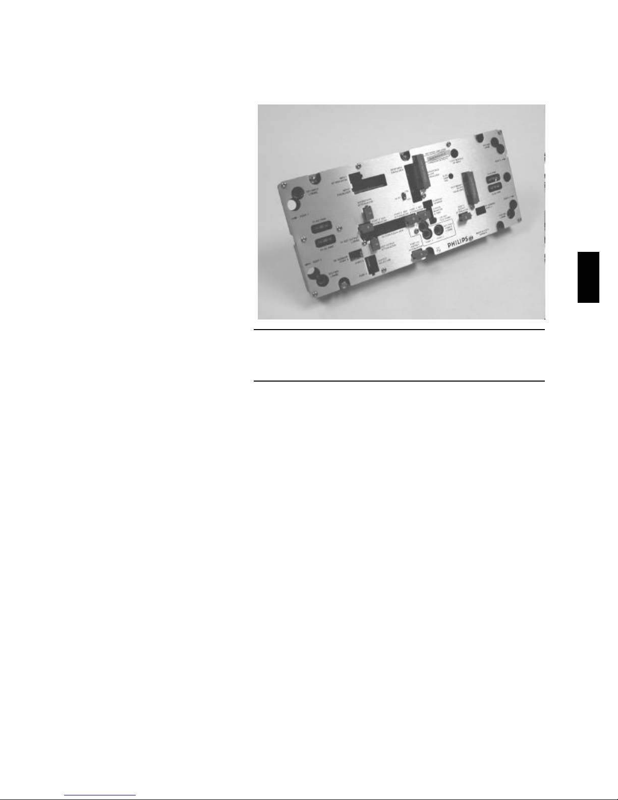
Figure 8. Diamond Line 2 Amplifier, Front View
The Diamond Line2 amplifier is a distribution amplifier, similar in
function to Philips’ GNA series global network amplifiers.
Diamond Line2 amplifiers have two equal, or three unequal,
high-level RF distribution outputs. They use two
post-amplifier hybrids, one for the main output and one for
the secondary outputs. A plug-in output port selector allows
you to use one or both secondary outputs by using a plug-in
jumper or directional coupler.
Diamond Line Amplifiers 10 July 2000 31
Page 4

Model Numbers (module only)
6 – G3A29_ /_ _– 42/54 – 4 _ _ – _ _ _
Power Doubling™
Technology
Same for Diamond
Line 2 & 3 Amplifiers
2 Output Hybrids
(Diamond Line 2
Amplifier)
Series 9
(1 GHz platform)
Highest Forward
Frequency—
7 = 750 MHz
8 = 870 MHz
Station Gain
37 dB
40 dB
(incl. losses from
ALSC and 1dB loss
from input equalizer)
42/54 Bandsplit (diplex filter)
5–42 MHz, return
54 MHz and up, forward
ALSC Pilot Frequency—
for example
427 = 427.25 MHz
433 = 433.25 MHz
499 = 499.25 MHz
Station Output Tilt
(over the forward
bandwidth)—
080 = 8.0 dB
125 = 12.5 dB
110 = 11.0 dB
100 = 10.0 dB
147 = 14.7 dB
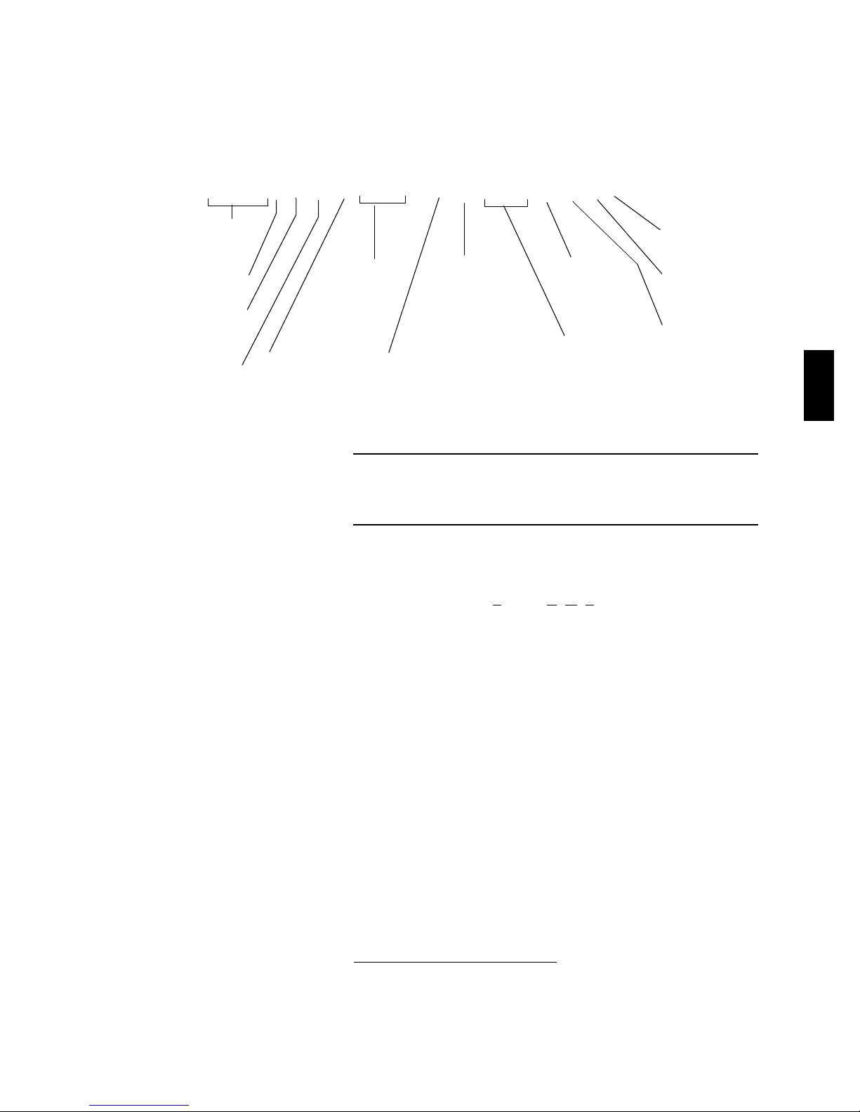
Figure 9. Diamond Line 2 Amplifier, Model Numbers
The Diamond Line2 amplifier modules vary in highest forward
frequency, ALSC pilot frequency, and station output tilt.
Diamond Line2 amplifier models vary in three ways: highest
forward frequency, automatic level and slope control (ALSC)
pilot frequency, and station output tilt. For example, model
6-G3A298
/37–42/54–433–100 (variableelements
underlined) specifies the following:
32 10 July 2000 Diamond Line Amplifiers
• a highest forward frequency of 870 MHz,
• a 433.25 MHz ALSC pilot frequency, and
• 10 dB station output tilt over the forward bandwidth.
Page 5
Diamond
Configuration Numbers (module + housing)
G3A62 _ D_ _– C_ L _ 9 _C1
Same for Diamond
Line 2 & 3 Amplifiers
Power Doubling™
Technology
2 Output Hybrids
(Diamond Line 2
Amplifier)
Highest Forward
Frequency—
7 = 750 MHz
8 = 870 MHz
42/54 Bandsplit
ElementManagement
(EMS) Capable
Station Gain
37 dB
40 dB
(incl. losses from
ALSC and 1dB
loss from input
equalizer)
Powering—
90 VAC,
3A power
supply
Housing—
A = None
B = 9-NHD-15/I/PED
K = 9-NH15
L = 9-NH15/CA
M = 9-NH15/I
R = 9-NH15/I/PED/CA
V = 9-NHD-15
(Also compatible with
9-BH15 series housings)
Plug-In Return
Amp Hybrid
ALSC Pilot
Frequency—
LD = 423.25 MHz
LE =426.25 MHz
LF = 427.25 MHz
LG = 433.25 MHz
LJ = 499.25 MHz
Surge
Protection—
90V Crowbar
Station Output
Tilt (athighest
frequency)—
2 = 12.5 dB
3 = 11.0 dB
4 = 10.0 dB
5 = 14.7 dB
Figure 10. Diamond Line 2 Amp, Configuration Numbers
A Diamond Line2 amplifier configuration combines a particular
amplifier module with a particular housing.
Diamond Line2 amplifier configuration numbers tell which
amplifier module is installed in which housing. Forexample,
configuration G3A628
D37-CVLG94C1 (variableelements
underlined) specifies the following:
• a Diamond Line2 amplifier module like the example given
on page32 (highest forward frequency of 870MHz, ALSC
pilot frequency of 433.25 MHz, and 10dB station output
tilt athighest frequency) and
• a 9-NHD-15 housing (9-NH15 series housing with deep
lid, as required for element management). For more on
9-NH housing model numbers, see page49.
1. Diamond Line series amplifiers can also be housed in 9-BH15 series bypass
housings. See “9-BH15 Series Amplifier Housing,” starting on page57.
Diamond Line Amplifiers 10 July 2000 33
1
Page 6
Functional Description
For details on the forward
RFsignal flow, see page35.
Fordetails on the return
RFsignal flow, see page38.
For a description of amplifier
powering, see page39.
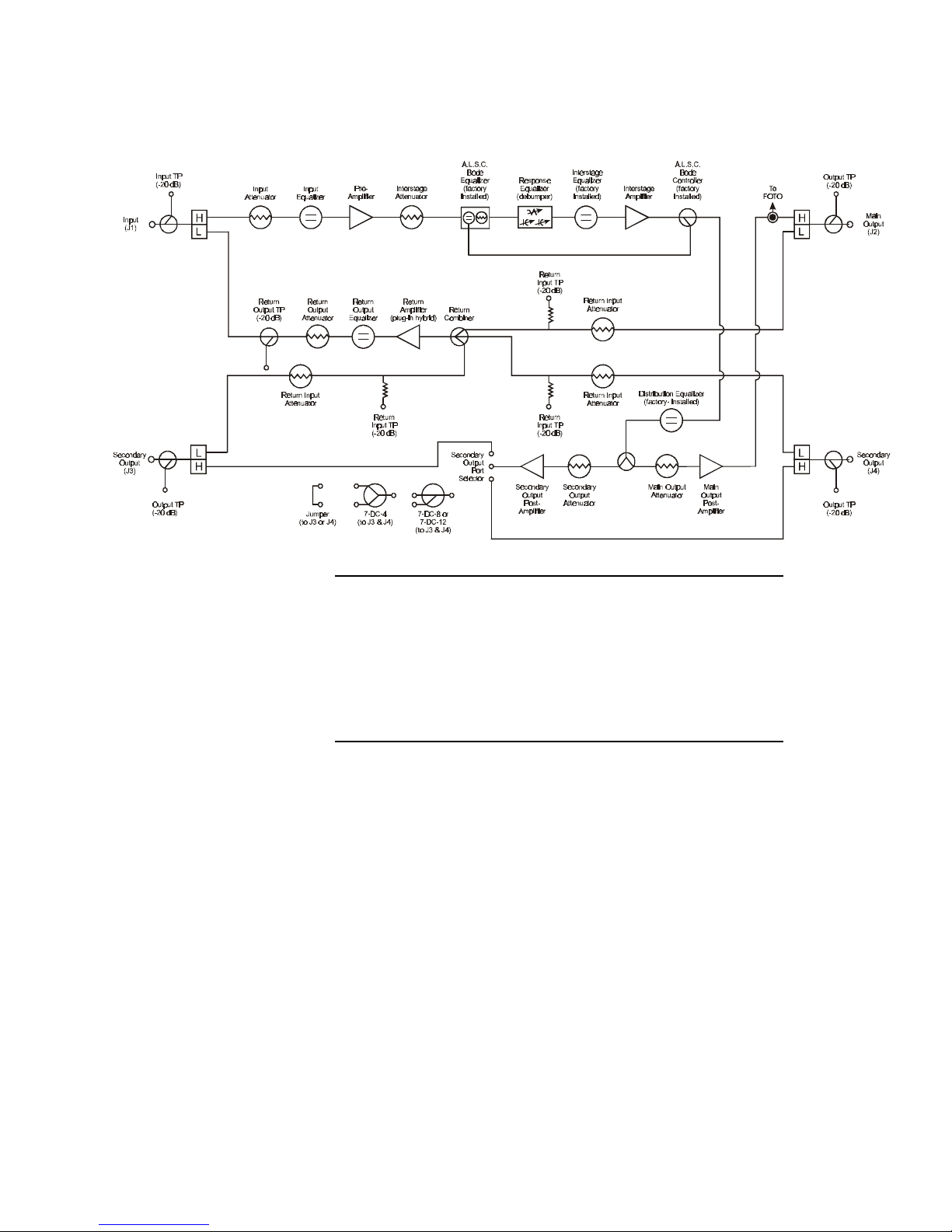
Figure 11. Diamond Line 2 Amp, Functional Block Diagram
The Diamond Line2 amplifier can have two equal, or three
unequal, high-level RF distribution outputs. It uses two
post-amplifier hybrids, one for the main output and one for the
two secondary outputs. A plug-in output port selector lets you
use one or both secondary outputs by using a plug-in jumper or
directional coupler.
In summary, forward RF signals enter the Diamond Line2
amplifier module through the input port, J1, and are amplified
by the pre-amplifier. The main output signals are amplified
twice more before exiting through the main output port, J2.
The secondary-output signals are also amplified twice more
before exiting through the two distribution (secondary)
output ports, J3 and/or J4.
The return RF signal flow is the same for all three of the
Diamond Line2 amplifier’s return legs, from ports J2, J3,
and/or J4 to portJ1.
34 10 July 2000 Diamond Line Amplifiers
Page 7

Diamond
Forward RFSignalFlow Before Main & Secondary Paths Split
Input Port (J1). The input port, J1, routes forward incoming
signal to the amplifier. (This port also routes outgoing return
signal to the main cable.)
Refer to Figure11 as you
read the descriptions in this
section.
Amplifiers are shipped with
the input attenuator and
input equalizer positions
empty; you must plug both
circuits in for the amplifier to
work.
Input Test Point. The input test point is a -20 dB directional
coupler. Accessible through a cut-out in the module cover,
this test point lets you verify the forward signals at the
forward input port(J1) without interrupting the amplifier’s
operation. (Return signal cannot be measured here.)
Input Diplex Filter. A diplex filter consists of a pair of filters, a
high-pass and a low-pass, isolating forward and return bands.
The high-pass filter passes forward signals but blocks return
signals and AC. The low-pass filter passes return signals but
blocks forwardsignals.
Input Attenuator. A 9-A-WC or 10-A-WC series plug-in
attenuator reduces RF levels at the pre-amp input to meet
design specifications. Amplifiers are shipped with the input
attenuator position empty. Select and install the appropriate
value based on the amplifier’s location in your network.
Input Equalizer. The 7-2E-WC series plug-in equalizer
compensates for the effects of cable precedingthe amplifier
module. Amplifiers are shipped with the input equalizer
position empty. Select and install the appropriate value based
on the amplifier’s location in your network.
Pre-Amplifier. A push-pull input hybrid provides gain. This
pre-amplifier sets the amplifier’s noise figure.
Interstage Attenuator. A 9-A-WC or 10-A-WC series
interstage attenuator reduces overall amplifier gain. A “zero”
attenuator is shipped in this slot for circuit continuity.
ALSC Bode Equalizer (factory-installed). The ALSC Bode
equalizer works with the ALSC Bode controller to maintain a
constant RF output level, compensating for the effects of
outside temperature changes on cable.
Response Equalizer. An EDB series response equalizer
(debumper) flattens the forward response of cascaded
amplifiers, compensating for system signature imperfections.
A jumper is shipped in this slot for circuit continuity.
Diamond Line Amplifiers 10 July 2000 35
Page 8

Forward RFSignalFlow
(Cont.)
Interstage Equalizer (factory-installed). The 7-2E-WC series
equalizer is factory-installed to optimize the distortion
characteristic of the amplifier and provide the desired main
output slope at the specified bandwidth. Normally you will
not change this plug-in. However, if you need to change the
tilt of the amplifier’s outputs from the factory-set value, see
the procedure under “Interstage & Distribution Equalizers”
on page160.
Interstage Amplifier. The RF from this hybrid, which uses
push-pull technology, goes to the two post-amplifiers.
ALSC Bode Controller (factory-installed). The automatic level
and slope control (ALSC) Bode controller works with the
ALSC Bode equalizer to maintain a constant RF output level,
compensating for the effects of outside temperature changes
on cable. A directional coupler taps a small portion of the
main output power and converts it to a DC signal that
controls the Bode equalizer.
Distribution Equalizer (factory-installed). The 7-2E-WC series
distribution equalizer provides additional slope to all outputs.
The interstage and distribution equalizers are factory-installed
to set the tilt of the output signals according to the customer
order. A “zero” equalizer may be shipped in the distribution
equalizer position for circuit continuity if no additional slope is
needed. Normally you will not change this plug-in. However,
if you need to change the tilt of the amplifier’s outputs from
the factory-set value, see the procedure under “Interstage &
Distribution Equalizers” on page160.
36 10 July 2000 Diamond Line Amplifiers
Main Path (after it splits from secondary path)
Main Output Attenuator. Accessible through a cut-out in the
module cover, this 9-A-WC or 10-A-WC attenuator reduces
signal levels at the main output. A “zero” attenuator is
shipped in this slot for circuit continuity.
Main Output Post-Amplifier. The RF from this hybrid, which
uses Power Doubling technology, goes to the main output
port, J2.
Main Output Diplex Filter. See “Input Diplex Filter” on
page35.
Page 9

Diamond
The main output test point
allows access to the return
band as well. You can’t
measure return signal here,
but you can inject return test
signals.
Main Output Test Point. The main output test point is a
-20dB directional coupler, which isolates the measured
forward signal from the effects of reflections in the cable.
Accessible through a cut-out in the module cover, this test
point lets you verify the forward signals at the main output
port (J2) without interrupting the amplifier’s operation.
Main Output Port (J2). The main output port, J2, routes
forward outgoing signal to a distribution cable. (This port also
routes incoming return signal to the amplifier.)
Secondary Path (after it splits from main path)
Secondary Output Attenuator. A 9-A-WC or 10-A-WC series
attenuator reduces signal levels at the secondary output port
(J3 or J4). A “zero” attenuator is shipped in this slot for circuit
continuity.
A secondary output test point
allows access to the return
band as well. You can’t
measure return signal here,
but you can inject return test
signals.
Secondary Output Post-Amplifier. The RF from this hybrid,
which uses Power Doubling technology, goes to the
secondary output port(s).
Secondary Output Port Selector. Accessible through a cut-out
in the module cover, the output port selector directs signal to
the secondary output port(s): J3 only, J4 only, or both J3 and
J4. A jumper, or “zero” attenuator, is used when directing
signal to only one port. When using both ports, this location
accepts a DC4-WC, DC8-WC, or DC12-WC directional
coupler plug-in.
Secondary Output Diplex Filter. See “Input Diplex Filter” on
page35.
Secondary Output Test Point. A secondary output test point is
a -20 dB directional coupler, which isolates the measured
forward signal from the effects of reflections in the cable.
Accessible through a cut-out in the module cover, this test
point lets you verify the forward signals at the secondary
output port (J3 or J4) without interrupting the amplifier’s
operation.
Diamond Line Amplifiers 10 July 2000 37
Secondary Output Port (J3 or J4). A secondary output port
routes forward outgoing signal to a distribution cable. (This
port also routes incoming return signal to the amplifier.)
Page 10

Return RF Signal Flow Before the Return Legs Combine
Return Input Port (J2, J3, or J4). A return input port routes
The signal flow is the same
for all three of the Diamond
incoming return signal to the amplifier. (This port also routes
forward outgoing signal to distribution cables.)
Line2 amplifier’s return legs.
Return Test Signal Injection Point (Output Test Point). Since the
Refer to Figure11 as you
read the descriptions in this
section. See also “Accurate
forward output test point allows access to the return band,
you can inject return test signals here (although you can’t
measure return signal).
return setup” on page10 for
a discussion of return-path
features and benefits.
Return Input Diplex Filter. See “Input Diplex Filter” on
page35.
Return Input Attenuator. A 9-A-WC or 10-A-WC series
plug-in attenuator is used in this position primarily for ingress
isolation. (See page163.) A “zero” attenuator is shipped in
this slot for circuit continuity.
Return Input Test Point. Accessible through a cut-out in the
module cover, this -20 dB resistive test point lets you verify
the return signals at the return hybrid input. It is
approximately -15dB from the test point’s position in the
circuit.
Amplifiers are shipped with
the return output equalizer
and return output attenuator
positions empty; you must
plug both circuits in for the
amplifier to work.
Return Combiner. Return signals from J2, J3, and J4 are
combined into a single feed for the return amplifier. This
three-way combiner has equal (5dB) loss in each leg.
After the Return Legs Combine
Return Amplifier. This hybrid, which amplifies the combined
return signal, features an improved compression point and bit
error rate (BER) for digital-loaded traffic over a discrete
amplifier design.
Return Output Equalizer. Accessible through a cut-out in the
module cover, the 7-REF-WC series equalizer provides an
output tilt at the return amplifier that will provide a flat input
at the next return amplifier. Amplifiers are shipped with the
return output equalizer position empty. Select and install the
appropriate value based on the amplifier’s location in your
network.
A return EDB plug-in may be installed instead of the
7-REF-WC series equalizer to flatten circuitry response
anomalies.
38 10 July 2000 Diamond Line Amplifiers
Page 11

Diamond
Return Output Attenuator. A 9-A-WC or 10-A-WC series
attenuator reduces signal levels at the return output port (J1).
Amplifiers are shipped with a “zero” return output
attenuator. You may need to select and install the appropriate
value based on the amplifier’s location in your network.
Return Output Test Point. This -20 dB directional coupler test
point is used to measure the combined return signal as it will
be sent to the return output port, J1. (Note that the test
point at J1 is for forward input only; combined return signal
cannot be measured at that point.)
Return Output Diplex Filter. See “Input Diplex Filter” on
page35.
Return Output Port (J1). The return output port routes
outgoing return signal via the cable system back to the
previous amplifier. (This port also routes incoming forward
signal to the amplifier.)
Amplifier Powering AC power may enter the housing at any of the RF ports.
ACand RF separation is fixed. An AC bypass path provides
high impedance to RF signals.
The amplifier’s 3-ampere power supply receives the incoming
AC power and converts it into DC power. For details on the
power-director fuses, see Figure45.
Diamond Line Amplifiers 10 July 2000 39
Page 12
Controls and Connectors
4. Input Test
Point,TP1
9. Fuses:
F1
F3
7. Return Output
TestPoint
5. Output Test
Point,TP3
10. ALSC
On/Off Switch
14. Location for
Port 3 RF Sensor
(DD-EMS Kit)
12. EMS & Power
Connector
6. Return Input
TestPoints
(forports 2, 3, & 4)
13. Location for
EMS Current
Sensor
15. EMS Module
RFInput
Connector
14. Location for
Port 4 RF Sensor
(DD-EMS Kit)
11. ALSC
Gain Control
5. Output Test
Point,TP2
9. Fuses:
F2
F4
8. +24 VDC
TestPoint
5. Output Test
Point,TP4
3. Secondary Output/
ReturnInput Jack,J3
1. Forward Input/
ReturnOutput Jack, J1
3. Secondary Output/
ReturnInput Jack,J4
2. Main Output/
ReturnInput Jack,J2
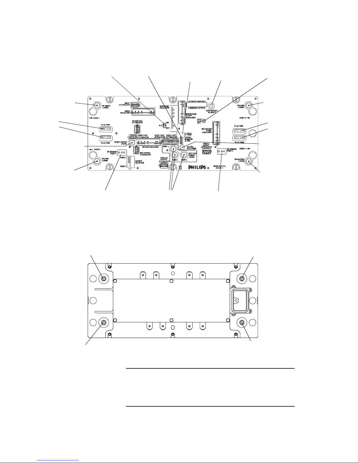
Figure 12. Diamond Line 2 Amp, Controls & Connectors
This illustration shows the Diamond Line2 amplifier module’s
controls and points of connection. Callouts are defined in the
following table. For locations of plug-in circuits, see page42.
40 10 July 2000 Diamond Line Amplifiers
Page 13

Diamond
Designation Description
1. Forward Input/ReturnOutput
Jack, J1
G-type female connector. Routes forward input to the amplifier. Also
routes return output via the cable system back to the previous amplifier.
AC can be received through any of the four ports (J1, J2, J3, or J4) to a
3-amp power supply.
2. Main Output/
ReturnInputJack, J2
G-type female connector. Routes forward output to the main cable. Also
routes return input to the amplifier. AC can be received through any of the
four ports (J1, J2, J3, or J4) to a 3-amp power supply.
3. Secondary Output/
ReturnInputJacks, J3 & J4
G-type female connectors. Route forward output to distribution cables.
Also route return input to the amplifier. AC can be received through any of
the four ports (J1, J2, J3, or J4) to a 3-amp power supply.
4. Input Test Point, TP1 -20 dB directional coupler test point. Used to measure the forward input
signal at J1 without interrupting the amplifier’s operation. Return output
signal cannot be measured here.
5. Output Test Points: TP2,TP3,
TP4
-20 dB directional coupler test points. Used to measure the forward
output signals at J2, J3, and J4, respectively, without interrupting the
amplifier’s operation. Directional coupler test points isolate the measured
forward output signal from the effects of reflections in the cable. The
output test points allow access to the return band as well. You can’t
measure return signal here, but you can inject return test signals.
6. Return Input Test Points (for
ports 2, 3, & 4)
-20 dB resistive test points. Used to measure the return signals before they
are combined, without interrupting the amplifier’s operation. Diamond
Line2 amplifiers, which combine return signals from multiple legs, use
resistive return input test points to minimize noise.
7. Return Output Test Point -20 dB directional coupler test point. Used to measure the combined
return signal as it will be sent to the return output port, J1.
8. +24 VDC Test Point Used to check the DC voltage.
9. Fuses: F1, F2, F3, F4 25-amp fuses. Direct AC power to ports J1, J2, J3, and J4, respectively.
10. ALSC On/Off Switch Switch located on ALSC circuit board. Turns automatic level and slope
control on (automatic mode) or off (manual mode).
11. ALSC Gain Control Potentiometer located on ALSC circuit board. Controls the gain set point
in automatic mode (ALSC on).
12. EMS & Power Connector Used to connect amplifier module to element-management
equipment in
lid of housing (deep-lid model required).
13. Location for EMS Current
Sensor
14. Locations for Secondary Port
Used with element management system to monitor the current draw in
the amplifier module.
Used with element management.
RF Sensors (DD-EMS Kit)
15. EMS Module RF Input
Connector
Used to connect amplifier module to element-management equipment in
lid of housing (deep-lid model required).
Diamond Line Amplifiers 10 July 2000 41
Page 14
Plug-In Circuits
9-A-WC
or
10-A-WC
Interstage
Attenuator
9-A-WC
or
10-A-WC
Return
Output
Attenuator
9-A-WC or
10-A-WC
Input
Attenuator
7-2E-WC
Input
Equalizer
EDB
Response Equalizer
(debumper)
7-2E-WC
Interstage
Slope
Equalizer
9-A-WC or
10-A-WC
Return Input
Attenuators
9-A0 or 7-DC-862
Secondary Output
Port Selector
7-REF-WC
Return Output
Equalizer or
EDB Response
Equalizer
9-A-WC or
10-A-WC
Secondary
Output
Attenuator
9-A-WC or
10-A-WC
Main Output
Attenuator
7-2E-WC
Secondary
Slope
Equalizer
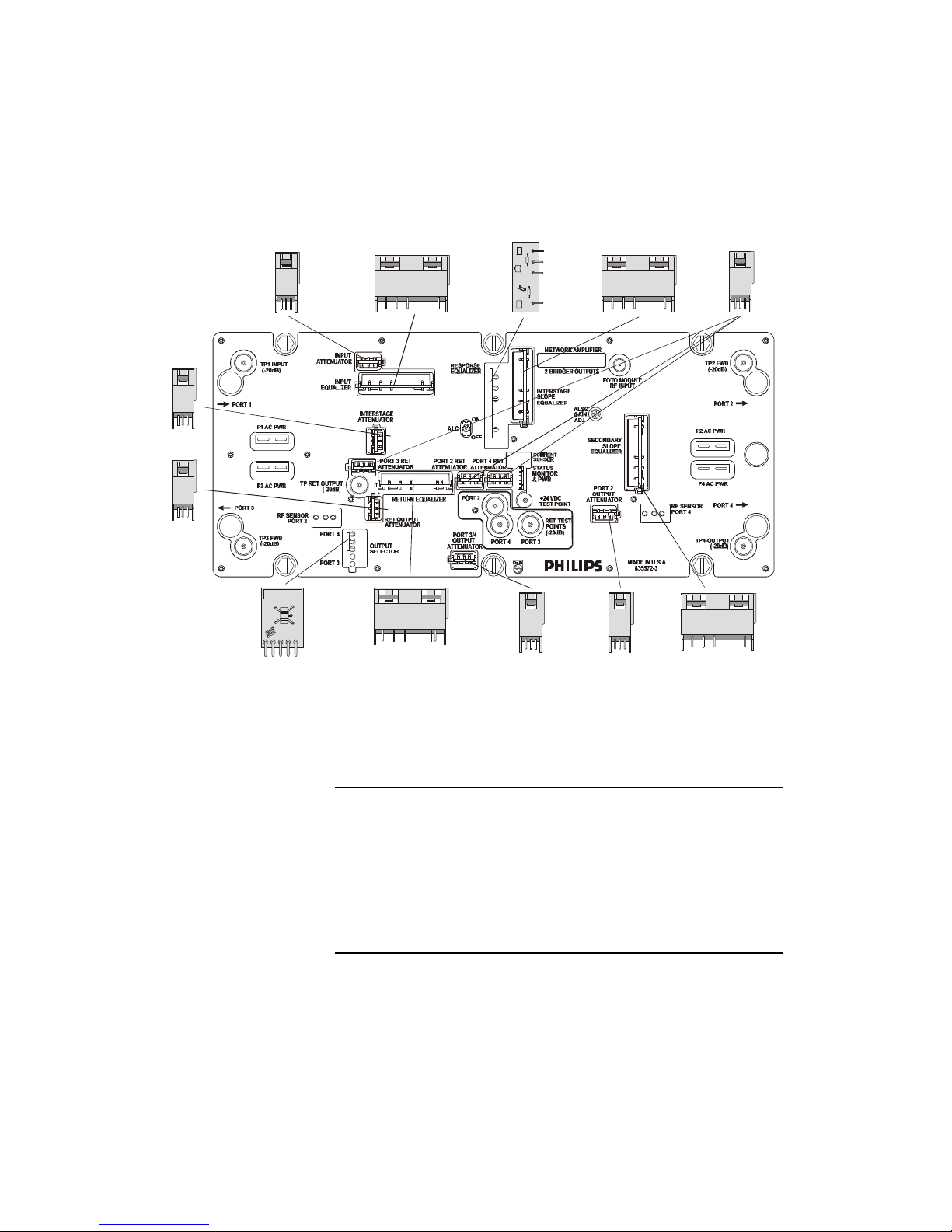
Figure 13. Diamond Line 2 Amp, User-Changeable Plug-Ins
These user-changeable plug-in circuits, accessible through
cut-outs in the amplifier cover, let you customize the Diamond
Line2 amplifier. “WC” series equalizers and attenuators come
with guides that simplify their installation and plastic covers that
protect their components. (The “WC” in the part number stands
for “with cover.”)
42 10 July 2000 Diamond Line Amplifiers
Page 15

Diamond
The illustration to the left shows what each user-changeable
plug-in looks like and where it goes in a Diamond Line 2
amplifier. For related information in this manual, see below:
Other information about these plug-ins Page
Which plug-ins are factory-installed, which required, which optional 43
How signal flows through the plug-ins & how they act on the signal 34
List of procedures related to each plug-in (in Index) 169
Plug-ins for a Diamond Line 2 Amplifier Plug-in Series
u Factory-Installed Plug-Ins
Circuits or jumpers are factory-installed in these positions for optimum performance according to customer or
product requirements. (The factory-installed plug-ins are shown in Figure13 only if they can be changed by the user.)
Automatic Level and Slope Control, ALSC (under cover, not user-changeable) 6-ALSC
Interstage Slope Equalizer* 7-2E-WC u
Distribution (Secondary) Slope Equalizer* 7-2E-WC u
Required Plug-Ins
•
These positions are shipped empty. For the amplifier to work, you must select and install the appropriate value
based on the amplifier’s location in your network. (The required plug-ins are all shown in Figure13.)
Input Attenuator 9-A-WC
or 10-A-WC
Input Equalizer 7-2E-WC
Return Output Equalizer 7-REF-WC
¢ Optional Plug-Ins
Jumpers, or “zero” value circuits, are shipped in these positions for circuit continuity. You may need to plug in different
values based on your system design and performance. (The optional plug-ins are all shown in Figure13.)
Interstage Attenuator 9-A-WC
or 10-A-WC ¢
Forward Response Equalizer (debumper) EDB ¢
Main Output Attenuator 9-A-WC ¢
or 10-A-WC ¢
Secondary Output Attenuator 9-A-WC ¢
or 10-A-WC ¢
Secondary Output Port Selector
If using one secondary output only (J3 or J4)
If using both secondary outputs (J3 & J4)
Return Input Attenuators (three locations) 9-A-WC ¢
Return Output Attenuator 9-A-WC ¢
Return Response Equalizer (debumper) EDB ¢
7-DC-862 ¢
or 10-A-WC ¢
or 10-A-WC ¢
u
9-A0
•
•
•
•
¢
¢
* Normally you will not change these equalizers. However, they are accessible through cut-outs in the module cover so that,
ifnecessary, you could change the tilt of the amplifier’s outputs from the factory-set value. See “Interstage & Distribution
Equalizers” on page160.
Diamond Line Amplifiers 10 July 2000 43
Page 16

Specifications
Diamond Line 2 Amplifier With 12.5 dB Tilt
Notes 6-G3A298/37-42/54-***-125 Units
Bandwidth
Forward
Return
Forward Minimum Full Gain @ 870 MHz
(incl. losses from ALSC) 38 +0.5/-0 dB
Forward Operating Gain @ 870 MHz
(incl. losses from ALSC and 1dB loss from input EQ) 37 +0.5/-0 dB
Return Operating Gain, minimum @ 40 MHz (incl. 1 dB loss from EQ) 17 dB
Response Flatness (forward and return)
Ports J2, J3 & J4 ±0.75 dB
Return Loss (75 ohm, all ports)
5–42 MHz
54–870 MHz
Test Points (forward and return) -20 ±0.5 dB
Forward Bandwidth
Referenced Output Level
at 870 / 750 / 650 / 550 / 54 MHz 48 / 46.5 / 45 / 43.5 / 35.5 dBmV
Channel Loading (analog, NTSC) a,b
Composite Triple Beat, typical -65 -70 -74 dBc
Cross Modulation, typical -66 -71 -74 dBc
Composite Second Order, typical
Vc + 0.75 & 1.25MHz only -65 -71 -74 dBc
Noise Figure, maximum (incl. 1 dB loss from EQ) 10 dB
Hum Modulation, typical
@ 12 amps
@ 15 amps
Return Bandwidth
Distortions at Referenced Output @ +25
Composite Triple Beat, typical -71 dBc
Cross Modulation, typical -66 dBc
Composite Second Order, typical -81 dBc
1 dB Compression Point, typical +69.5 dBmV
Noise Figure (worst case) 11 dB
Hum Modulation, typical
@ 12 amps (5–10 MHz / 11–42 MHz) 65 / 70 dBc
@ 15 amps (5–10 MHz / 11–42 MHz) 55 / 65 dBc
AC Bypass Current (continuous) 15 A
AC Power Consumption (worst case, @ 1.727 ADC) 48 W
Operating Ambient Temperature
Dimensions (length x width x height)
Weight 4.55 (2.0) lb (kg)
All specifications are subject to change without notice.
a. Distortion specifications are typical for individual module performance.
b. For performance using other channel spacing and loading schemes, refer to the Philips product catalog page RF-Amplifiers.
°C a,b 6 ch + 39 dBmV flat out
1
54–870
5–42
112 channels 96 channels 79 channels
-40 to 140
-40 to +60
12.8 x 5.6 x 3.6
32.5 x 14.2 x 9.1
16
16
-70
-65
MHz
MHz
dB
dB
dBc
dBc
°C
cm
°F
in.
1. See the Appendix for the following specifications, which apply to all Diamond Line amplifiers:
“Power Supply Specifications” on page151,
“Relative Chroma Delay Specifications, 42/54 Split (NTSCSystem M)” on page152,
“Relative Group Delay Characteristics forReturnSignals, 42/54 Split” on page152, and
“Automatic Level & Slope Control (ALSC) Specifications” on page154.
44 10 July 2000 Diamond Line Amplifiers
 Loading...