

Philips DDL193LAGCG/97, DDL193LAFGG/97, DDL193LAGGG/97, DDL193LAFCG/97, DDL193LAGBG/97 User guide
...Page 1
Page 2

Page 3

Contents
1 Important Information 02
Safety
Warning
Disposal of used products
and batteries
2 EasyKey Installation 03
Packing List
Exploded Views
Pre-install Instruction
Installation Steps
3 Get to know your
EasyKey 08
Outside Escutcheon
Inside Escutcheon
4 How to set up your
EasyKey 09
-Pre-setup Instruction
-Modify Master PIN Code
-User Settings
-Delete a user record
-System Settings
-Extended Functions
-System Query
-Local Query
-Bluetooth Settings
5 How to use EasyKey 15
Unlock
Unlock from Outside
-With a PIN Code
-With a Fingerprint
-With a Key Tag/Card
Unlock from Inside
-With a Rotator y Knob
-With a Functional Button
-With an Infrared Sensor
Lock
-Auto/Manual Mode
-Lock from Outside
-Lock from Inside
Indoor Deadlock
Mechanical Key Opening
6 Other Functions 18
Indoor Infrared Sensor Unlock
Restore to Default Sett ings
Mute Button
Outside Forced Lock
7 The Use and Meanings of
Indicators 20
Door Lock Status Indicator
Low Battery Voltage Indicator
Outside Forced Lock Indicator
Mute Indicator
Inside Deadlock Indicator
System Lock-up Indicator
[OPEN/CLOSE] Indicator
Indoor Infrared Sensor Unlock
Indicator
8 Troubleshooting 22
Alarm Types and Methods
How to use an Emergency Power
Supply
How to Replace Batteries
1
Page 4

1 Important information
Safety
◆Before using Philips EasyKey,
please read and understand all
instructions. Damage caused by noncompliance with the instructions
will not be covered by warranty.
◆Use only the manufacturerspecied accessories/components.
◆Use only the alkaline batteries
the product is equipped with,
or use the same specification
type of alkaline batter ies.
◆Do not forcibly disassemble
this product to avoid triggering an
alarm or damaging the product.
◆Do not scrape the ngerpr int
sensor with sharp objects, otherwise
it may cause permanent damage.
◆Do not expose products to
environments where there is
water leakage or splashing.
◆Do not expose the product to
corrosive substances to prevent
damaging the protective cover.
◆Do not hang objects on the
handle, in case it might aect
the normal use of the lock.
◆Pleae clean the product
with a soft cloth.
◆Do not remove the battery during
sett ing up and operating.
◆Please let a professional technician
to install the door lock and follow the
installation guidelines provided.Do not
disassemble the lock by yourself. Keep the
relevant sealed stickers properly. Do not
easily disclose the password informat ion.
◆Please modify the default master
PIN code immediately af ter nishing
installing and debugging, and keep
the mechanical key properly.
◆Please replace all the batteries
immediately if there is a low
battery alarm. Plea se make sure
to correctly match the poles (+/-)
when installing the batteries.
2
Caution
◆Do not place the battery near
re sources to avoid explosion.
◆Do not use any emergency power
supply that does not meet the safety
requirement s to power up the product.
◆Do not connect the 2 poles of the
batteries with metals to avoid shor t
circuit which may lead to an explosion.
◆Please make sure any component
replacement is executed by Philips,
Philips authorized service center
or professional technicians.
◆Do not use accessories or parts
that have been produced by other
manufacturers or have not been
specically recommended by Philips.
The use of such accessories and
parts may void your warrant y.
Disposal of used products
and batteries
◆You can have your locks reclaimed at
Philips authorized service centers. You
will receive corresponding compensation
if your products meet our conditions.
◆Please familiarize yourself with the
local electronic product collection system.
◆Please follow local regulations
and do not discard used products
into ordinary household waste.
◆Proper disposal of used products can
help to avoid potent ial negative impacts
on the env ironment and human health.
◆Batter ies must not be disposed of
with ordinary household waste.
◆Please familiarize yourself with the local
regulations on batteries classicat ion
recycling. Disposing of batter ies properly
can help avoid a negative impact on
the environment and human health.
Page 5
2 Easykey Installation
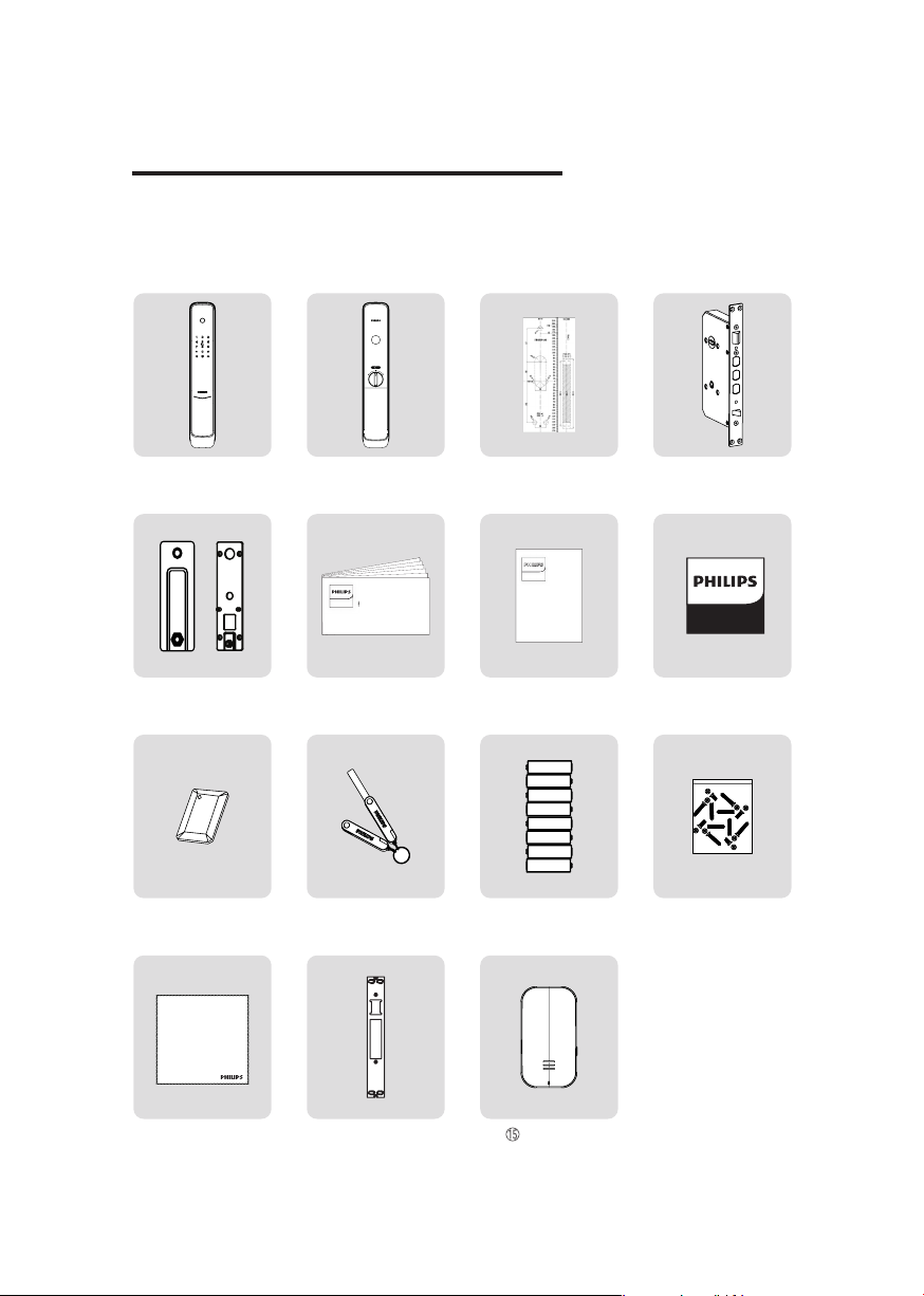
Packing List
This packing list is for reference only. Please refer to the actual pack ing items.
① Outside Escutcheon
with Silicone Pad
⑤ Mounting Plate
⑨ Key Tag X 2
② Inside
Escutcheon with
Silicone Pad
EasyKey易锁
Quick Start
Guide
⑥ Quick Start Guide
⑩ Mechanical
Key X 2
③ Drilling Templ ate
EasyKey
Warranty
Card
⑦ Warranty Card
⑪ Batteries
④ Mortise
EasyKey
⑧ Certicate of
Conformity
⑫ Installation kit
⑬ Cleaning Pad
⑭ Strike
Gateway
3
Page 6
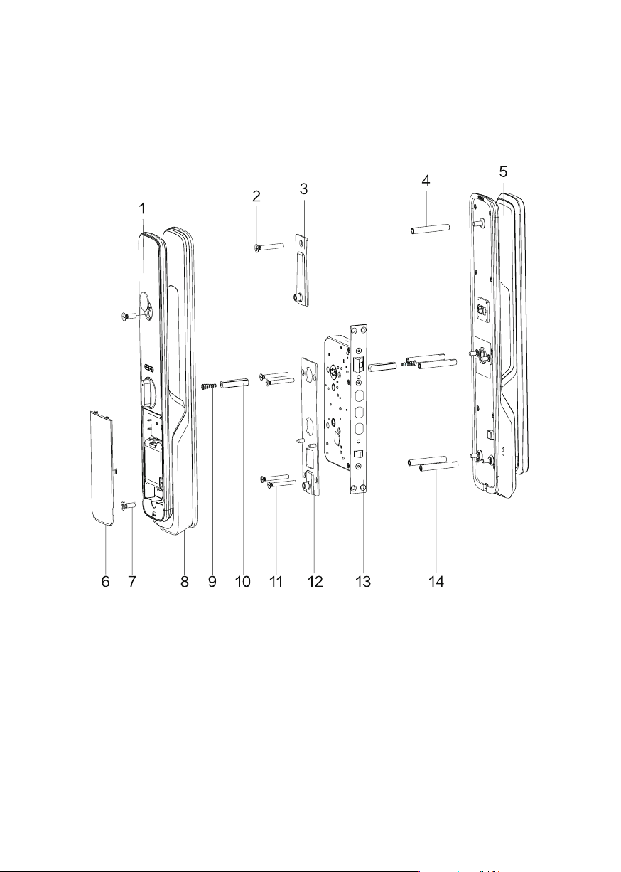
Exploded Views
1. Deco Cover
2. M6 Connect ing Screw
(X1)
3. Upper Mounting
Plate Set (X1)
4. M6 Connect ing Screw
Tub e ( X 1)
5. Outside Escutcheon
(X1)
4
6. Battery Cover
7. M6 Anchor Screw (X 2)
8. Inside Escutcheon
(X1)
9. Compressed Spring
(X2)
10. Square Shaf t (X2)
11. M5 Connecting Screw
(X4)
12. Mount ing Plate (X1)
13. Mortise (X1)
14. M5 Connecting
Screw Tube (X4)
Page 7
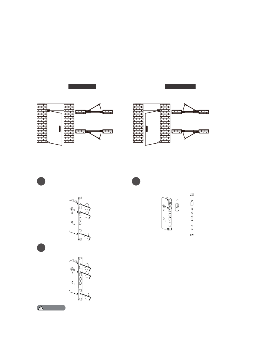
Pre-install Instruction
Step 1 | Check the door opening direction
This product can be installed on 4 types of opening direct ions: left-out pull,
right-in push, r ight-out pull and left-in push
Left-o pen Ri ght-op en
Indoor Indoor
Left-in
Outdoor
Indoor Indoor
Outdoor Outdoor
push
Leftout pull
Step 2 | Latch bolt direction change
Loosen the screws by turning
1
them clockwise with Allen
wrench and remove the mortise
plate.
guide plate
Allen wrench
Mount the mortise plate and
3
fasten it with screws.
guide plate
Allen wrench
Take out the latch bolt and
2
rotate it to 180°, then put it
back.
Oblique
tongue
Outdoor
Ri ghtin push
Ri ghtout pull
Attention
1. Plea se choose pr oper i nsta lla tion kit a s per the door t hickness .
2. The default inst all ation kit i s appl icab le for a do or thi ckness of 38- 60mm, if you r door thickn ess
does no t wit hin thi s rang e, please fe el free to cont act us .
5
Page 8
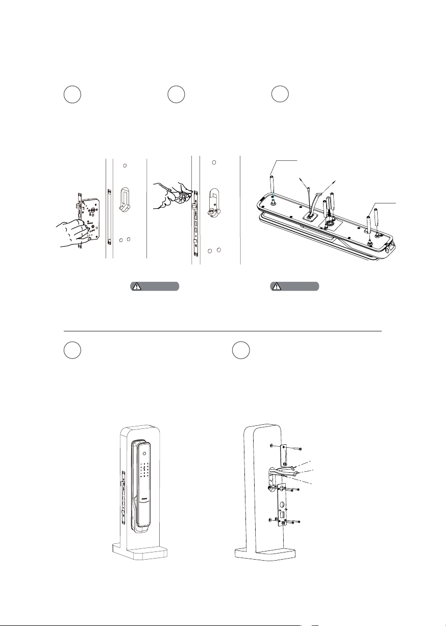
Installation Steps
To drill the needed
1
holes in the door
as per the drilling
template,then mount
the mor tise on the
door frame.
The la tch bol t can’t be poped
up during installation.
2
Attention Attention
Fasten the 4 anchor
screws in the
mortise.
To install the connect ing
3
screw tubes on the outside
escutcheon, and put the
compressed spring and
square shaf t accordingly
into the square shaft
holes.
M6 Conn ect ing
Sc re w Tu be
Front Bluetooth
Connecting Cable
Please use the appropr iate
square shaf t and connec ti ng
tubes w ith p rope r leng th.
Escutcheon
Connecting Cable
M5 Conn ect ing
Sc re w Tu be
Pass the connect ing cable through
4
the hole above the door. Align
the square shaft of the outside
escutcheon w ith the two rotar y
holes on the mor tise, then
inser t the square shaf t into the
rotary holes, so that the outside
escutcheon is close t in the outside
door.
First x the mounting plate
5
against the inner surface of the
door, and fasten it with 4 M5
connecting screws, and then x the
upper mounting plate with M6
connecting screws.
Mortise Connecting
Cable
Escutcheon
Connecting Cable
Front Bluetooth
Connecting Cable
6
Page 9
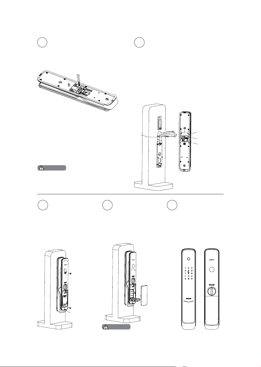
Put the compressed spring and
6
square shaf t into the square shaf t
hole of the inside escutcheon
accordingly.
Insert the outside escutcheon
7
connection cable and the motor
cable into the corresponding
sockets on the inside escutcheon,
and then connect the front and
rear Bluetooth connecting cables,
and then align the square shaft
of the ins ide escutcheon with the
two rot ary holes on the mortise,
then insert the square shaft into
the rotary holes, so that the inside
escutcheon is close t in the ins ide
door.
Attention
Be sure to hide th e ext ra mor ti se and t he
escut cheon connecting cables in t he door hole,
and al so hid e the ex tra B lueto oth con necting
cable in the inside escutcheon.
Unscrew the deco
8
cover by turning it
counterclock wise, and
press the bat tery cover
button to remove the
battery cover. Then
the two M6 mounting
screws can be installed
Turn clockwise to
9
install the deco cover,
install the battery, put
the bat ter y cover back,
and af ter at tach the
strike, the installation
of the sma rt lock is
complete.
to fasten the inside
escutcheon.
Front Bluetooth
Connecting Cable
To check whether
10
if the rot ary knob,
mechanical keys,
and all other
components could
be used normally.
Mortise Connecting
Cable Socket
Escutcheon Connecting
Cable Socket
Rear Bluetooth
Connecting Cable
Batt ery cover
button
Attention
Afte r compl eting the in sta llat ion
of the strike,please check whether
the sma rt lo ck can b e used
normally.
7
Page 10
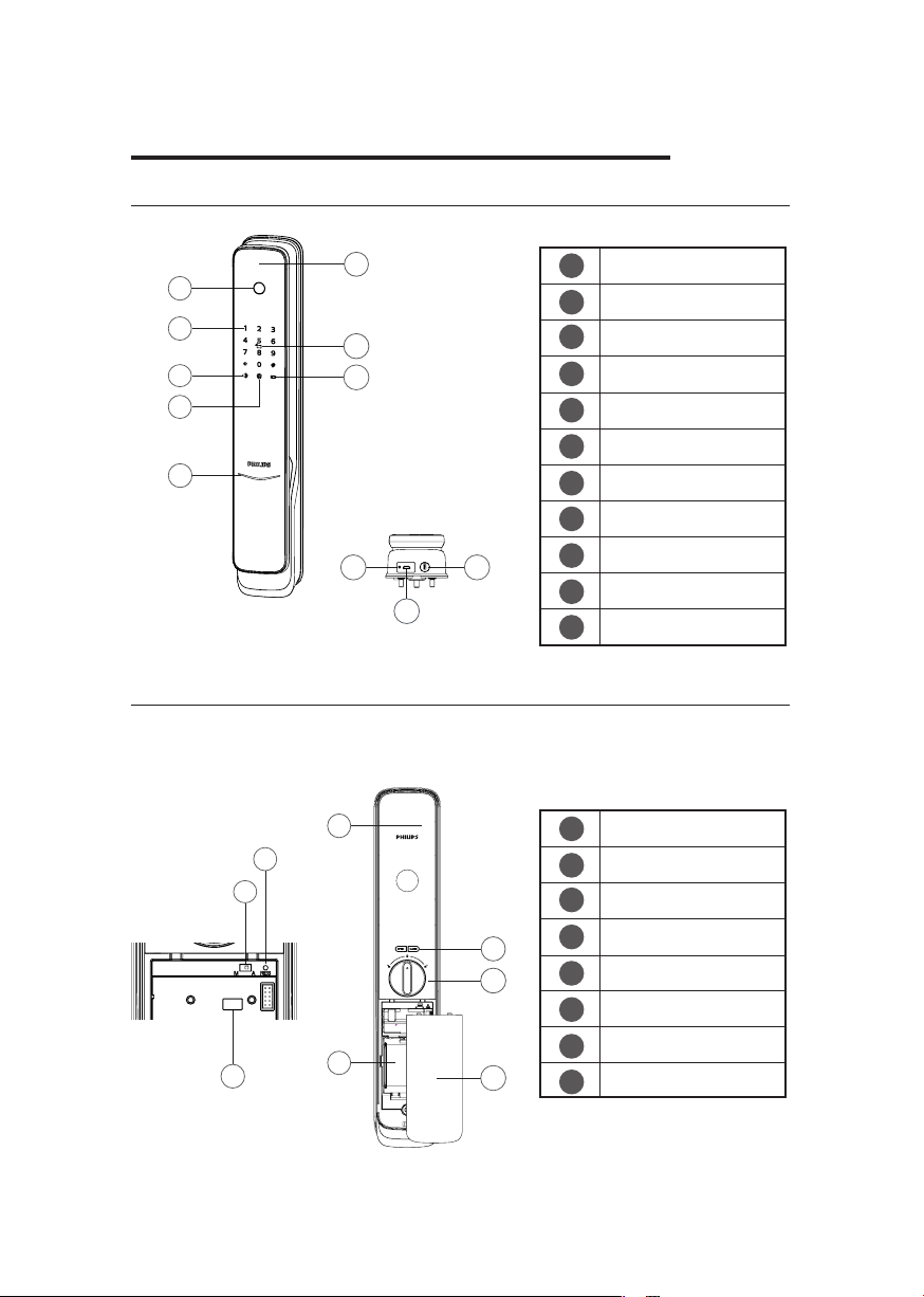
3 Get to know Your EasyKey
Outside Escutcheon
6
1
2
3
4
5
7
8
9 10
Inside Escutcheon
1
4
3
5
2
1
Fingerprint Sensor
Keypad
2
3
Mute Button
Outside Forced Lock
4
Button
5
Lock Status Indicator
6
Handle
Card Reader
7
Low Battery Voltage
8
Indicator
Reboot
9
Mechanical Key
11
6
7
8
10
Emergency power
11
supply port
Handle
1
2
Battery Cover
Auto/Manual Mode
3
Switch
4
RESET
Network Communicat
5
-ion Module Interface
6
OPEN/CLOSE Button
7
Rotary Knob
Battery Cover
8
8
Page 11
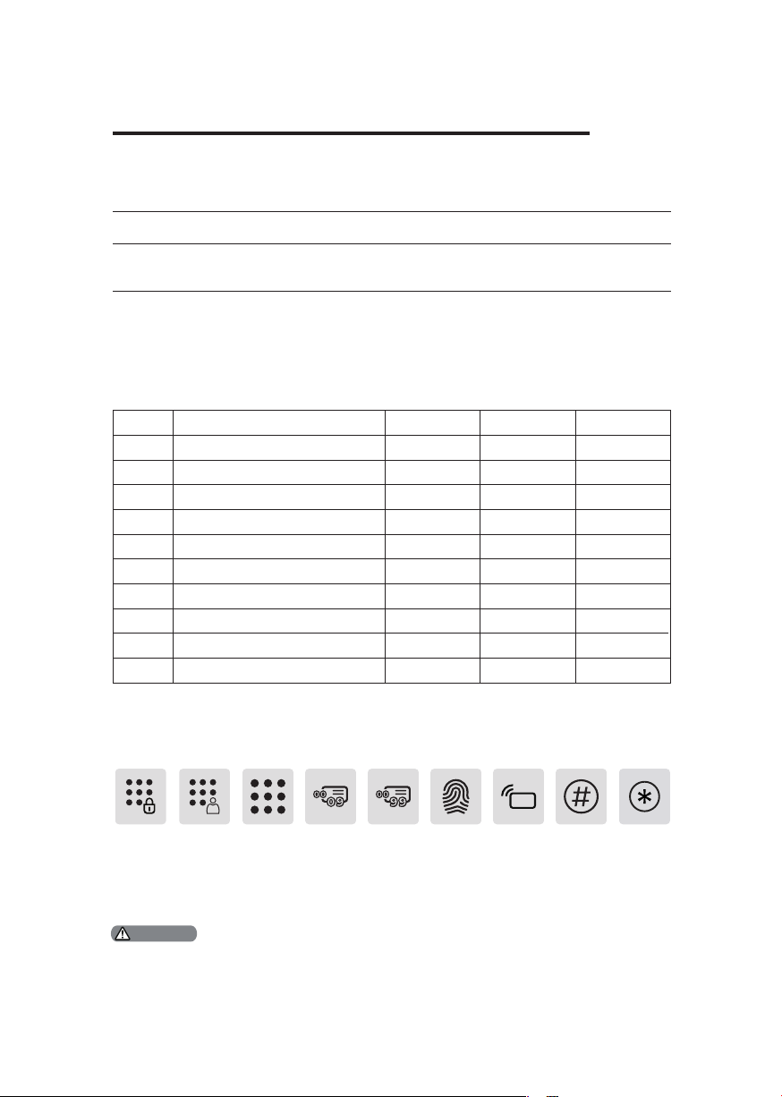
4 How to set up your EasyKey
Pre-install Instruction
◆There are two modes for the EasyKey System: general mode and dual ver ication
mode.
General Mode Dual Verication Mode
Unlock w ith any of the
registered identif y methods
◆User Code
When you want to delete one single user record, you could delete it in the system by
delet ing its user code.
◆You could ll in the below bl ank sheet with the user informat ion in case you might
need to check or review in the future.
00
01
02
03
04
05
06
07
08
09
Unlock w ith any two of the reg istered identify
methods among PIN code, Key Tag, and
Fingerprint
CardPIN CodeFingerprintNameNumber
◆Icon annotation
Master
PIN code
1.Press [*] key t o retur n to the p revious me nu.
2.The def ault ma ste r PIN code is 12345678 .
One-t ime
user PIN
Attention
code
User PIN
code
User
code
00-09
User
code
00-99
Finger
print
Ke y Ta g /
Card
#
*
9
Page 12
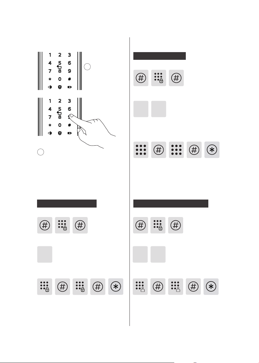
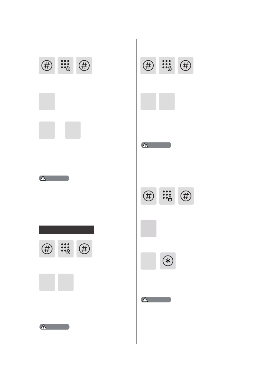
◆How to enter into Master Mode
1
Light up the
keypad.
User settings
Add a user PIN code
Enter [#], then enter master PIN code
and conrm with [#].
2
Press [#] before inputt ing any other
numbers. Af ter hear ing a voice prompt
of "Enter master PIN code", enter your
master PIN code and conrm with [#].
Then you are in ma ster mode.
Modif y master PIN code
Enter [#], enter master PIN code and
conrm w ith [#].
1
Enter [1] to modify master PIN code.
2
Enter [2] to add a user record, then enter
[1] to add a new user PIN code, and the
system will automatically number it and
generate a voice prompt.
Enter a user PIN code of 6 to 12 digits
and conrm with [#]. Then re-enter the
user PIN code and conrm w ith [#]. After
hear ing a voice prompt of “Succeeded”,
press [*] until you exit master mode.
Add a one-time User PIN Code
Enter [#], enter master PIN code and
conrm w ith [#].
1
2 2
Enter [2] to enter into user setting, then
enter [2] again to add a one-time user PIN
code.
Enter the new master PIN code and
conrm w ith [#] again. Re-enter
the same master PIN code and
conrm w ith [#]. After hear ing a
voice prompt of “Succeeded”, press
[*] to return to previous menu until
you nally exit master mode.
10
Enter a one-time user PIN code of 6 to
12 digits and conrm with [#]. Then reenter the one-time user PIN code and
conrm w ith [#]. After hear ing a voice
prompt of “Succeeded”, press [*] until
you exit master mode.
Page 13
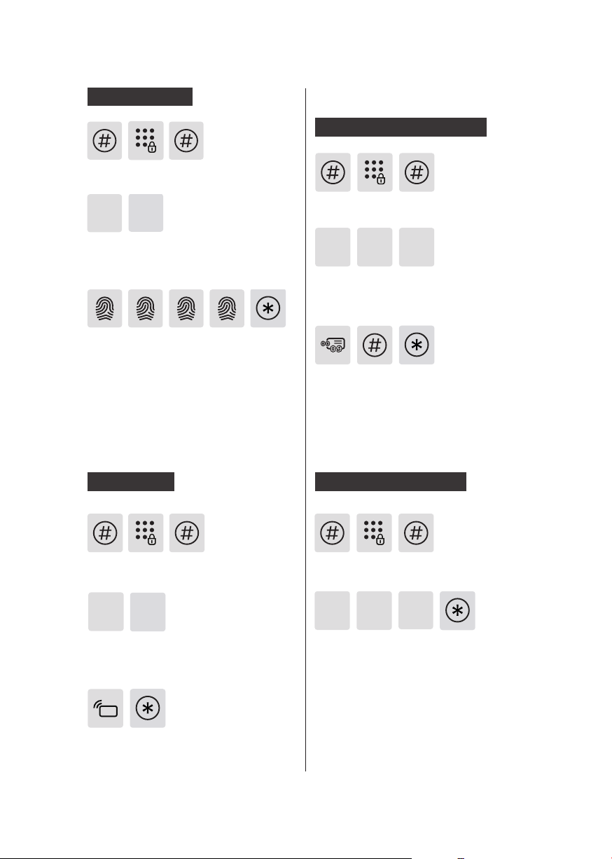
Add a Fingerprint
Enter [#], enter master PIN code and
conrm w ith [#].
2
Enter [2] to add a user record, then enter
[3] to add a user ngerpr int, and the
system will automatically number it and
generate a voice prompt.
Place your nger against the sensor.
After hear ing a voice prompt of “Take
away your nger and enroll again”,
please take away your nger and replace it against the sensor. After hear ing
a voice prompt of “Succeeded”, press [*]
until you exit master mode.
3
Delete a User Record
Delete a single User PIN Code
Enter [#], enter master PIN code and
conrm w ith [#].
1 13
Enter [3] to delete a user record, then
enter [1] to delete a user PIN code, and
then enter [1] to delete a single user PIN
code.
Enter a user code (code: 00-09) of 2
digits and conrm with[#]. After hearing
a voice prompt of “Succeeded”, press [*]
until you exit the master mode.
Add a Key Tag
Enter [#], enter master PIN code and
conrm w ith [#].
2
4
Enter [2] to add a user record, then
enter [4] to add a user key tag, and the
system will automatically number it and
generate a voice prompt.
Place the key ta g against the card reader
until you hear a beep. After hear ing a
voice prompt of “Succeeded”, press [*]
until you exit the master mode.
Delete All User PIN Codes
Enter [#], enter master PIN code and
conrm w ith [#].
3
Enter [3] to delete a user record, then
enter [1] to delete a user PIN code, and
then enter [2] to delete all user PIN
codes. After hearing a voice prompt of
"Succeeded", press [*] until you exit the
master mode.
1
2
11
Page 14
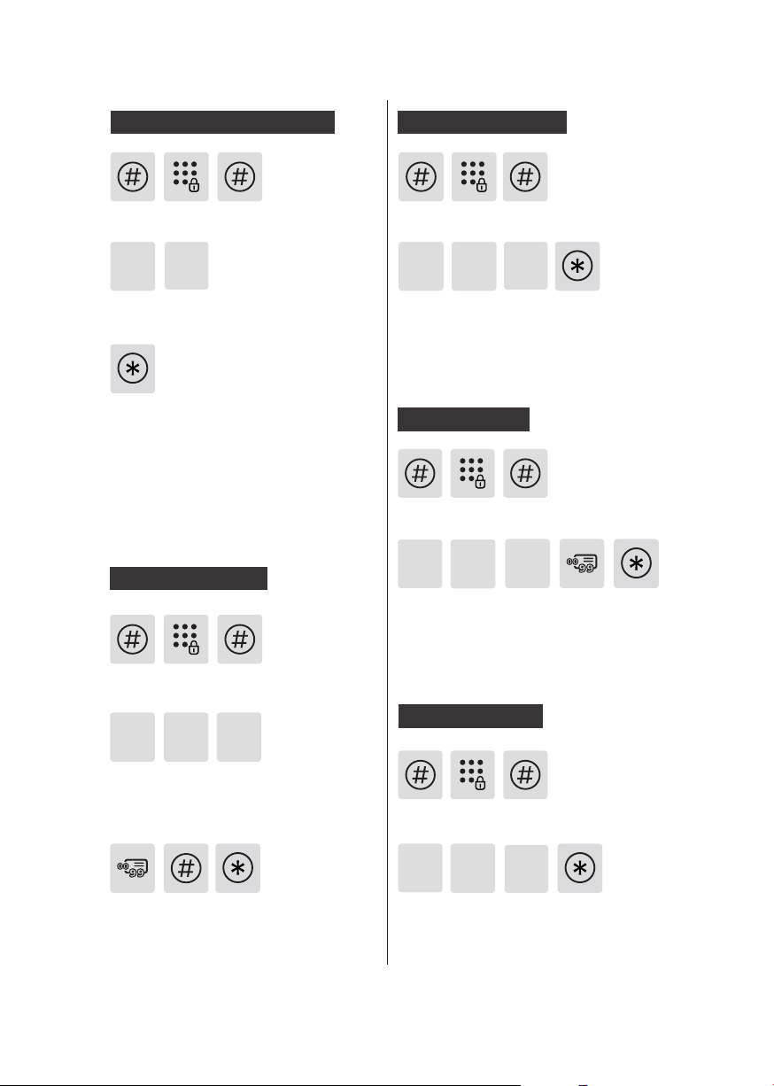
Delete all One-time PIN Codes
Delete All Fingerprints
Enter [#], enter master PIN code and
conrm w ith [#].
3
Enter [3] to delete a user record, then
enter [2] to delete all one-time user PIN
code.
After hear ing a voice prompt of
“Succeeded”, press [*] until you exit the
master mode.
Delete a Fingerprint
Enter [#], enter master PIN code and
conrm w ith [#].
2
Enter [#], enter master PIN code and
conrm w ith [#].
3 3
Enter [3] to delete a user record, then
enter [3] to delete ngerprint record, and
then enter [2] to delete all ngerpr int
records. After hearing a voice prompt of
"Succeeded", press [*] until you exit the
master mode.
Delete a Key Tag
Enter [#], enter master PIN code and
conrm w ith [#].
3
4
Enter [3] to delete a user record, then
enter [4] to delete key t ag record, a nd
then enter [1] to delete one single key
tag record. After hear ing a voice prompt
of “Succeeded”, press [*] until you exit
the master mode.
Delete All Key Tags
2
1
3 3
Enter [3] to delete a user record, then
enter [3] to delete ngerprint record,
and then enter [1] to delete one single
ngerprint record.
Enter the 2-dig it [user number] (00-99)
of the ngerpr int that is to be deleted
and conrm with [#]. After hearing a
voice prompt of “Succeeded”, press [*]
until you exit the master mode.
12
1
Enter [#], enter master PIN code and
conrm w ith [#].
3
4
Enter [3] to delete a user record, then
enter [4] to delete key t ag record, a nd
then enter [2] to delete all key tag
records. After hearing a voice prompt of
"Succeeded", press [*] until you exit the
master mode.
2
Page 15
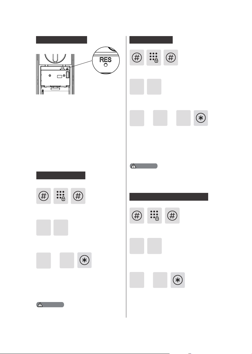
System Initialization
Remove the battery cover, then double
press the [RES] hole w ith a sharp
object, af ter hearing a voice prompt of
“Restoring to default set tings”, all user
information will be emptied.
Volume Settings
Enter [#], then enter master PIN code
and conrm with [#].
24
Enter [4] to get into system settings, then
enter [2] to enter into volume settings.
or or
1
Choose the volume as needed: For
high volume, press [1]; for low volume,
press [ 2]; for mute mode, press [3]. After
hear ing a voice prompt of “Succeeded”,
press [*] until you exit the master mode.
2
3
System Settings
Language Settings
Enter [#], enter master PIN code and
conrm w ith [#].
4
Enter [4] to get into system settings,
then enter [1] to get into l anguage
settings.
1
Choose the la ngua ge as needed: For
Chinese, press [1]; for English, press
[2]. After hearing a voice prompt of
“Succeeded”, press [*] until you exit the
master mode.
The default language is English.
1
or
Attention
2
Attention
The default volume is “high volume”.
Switch to Dual Verication Mode
Enter [#], then enter master PIN code
and conrm with [#].
4
Enter [4] to get into system settings,
then enter [3] to enter into ident ify
verication methods portfolio.
For single ver ication method, press
[1]; for dual ver ic ation method, press
[2]. After hearing a voice prompt of
“Succeeded”, press [*] until you exit the
master mode.
1
or
3
2
13
Page 16
Extended Functions
Local Query
Enter [#], enter master PIN code and
conrm w ith [#].
5
Enter [5] to get into extended funct ions.
or
1
To join a network, press [1]. To exit a
network, press [2]. Before sett ing up the
extended funct ions, please download
and open Philips EasyKey (APP) from
App Stores via your phone.
Attention
The extended functions are optional.
System Query
Secur ity Code Query
Enter [#], enter master PIN code and
conrm w ith [#].
6
Enter [6] to get into system query, then
enter [1] to get into securit y code query,
the system will broadcast the product
series number automatically.
Attention
Directly input 40 0# coul d enter i nto system
que ry.
2
1
Enter [#], enter master PIN code and
conrm w ith [#].
6
Enter [6] to get into system query,
then enter [2] to get into product
soft ware version query, the system will
broadcast the product soft ware version
automatically.
Directly input 11 4# could enter into local query.
2
Attention
Bluetooth Settings
Enter [#], then enter master PIN code
and conrm with [#].
7
Enter [7] to get into Bluetooth sett ings
menu.
3
To disable Bluetooth, please press [3].
After hear ing a voice prompt of “Settings
succeeded”, press [*] unt il you exit the
master mode.
Attention
1.Directly input 403# to enable Bluetooth , and
input 4 04# to d isable Bluetooth.
2.When t he Bluetooth is o, plea se press [1] t o
enable Bluetooth.
3. When using the new ly updated Ea syKey App
to bind w ith the smart loc k, use rs cou ld foll ow
up the ch apter of “Add a dev ice” to nish th e
binding process.
14
Page 17
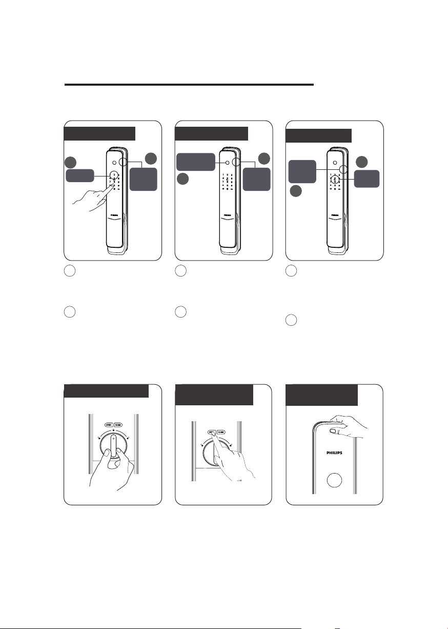
5.How to use your EasyKey
Unlock | Unlock from outside
With a PIN code
1
Keypad
1
Touch and wake up
the keypad, then enter a
registered user PIN code
and conrm with [#].
2
After hear ing a voice
prompt of “Door opened”,
push or pull the handle to
open the door.
Push or
pull to
unlock
With a ngerpr int
2
Fingerprint
sensor
1
1
Place the nger of
which the ngerprint has
been registered against
the sensor.
2
After hear ing a voice
prompt of “Door opened”,
push or pull the handle to
open the door.
Push or
pull to
unlock
Unlock | Unlock from Inside
With a Rot ary Knob
With a Functional
Button
With a Key Tag
2
Push or
pull to
unlock
2
1
Place the key ta g/
card that has been
successfully registered
properly against the card
reader.
2
After hear ing a voice
prompt of “Door opened”,
push or pull the handle to
open the door.
With an Infrared
Sensor
1
Card
reader
Philips EasyKey employs
indoor fast opening
mort ise. You can unlock
from inside by rotat ing
the rotary knob.
Double press the [OPEN/
CLOSE] functional but ton
within one second, then
push or pull to unlock.
Features with an infrared
sensor on the handle, when
the sensor is triggered, hold
the handle’s sensor modules
on both the front and rea r
side simultaneously,you
could ea sily unlock the door.
15
Page 18
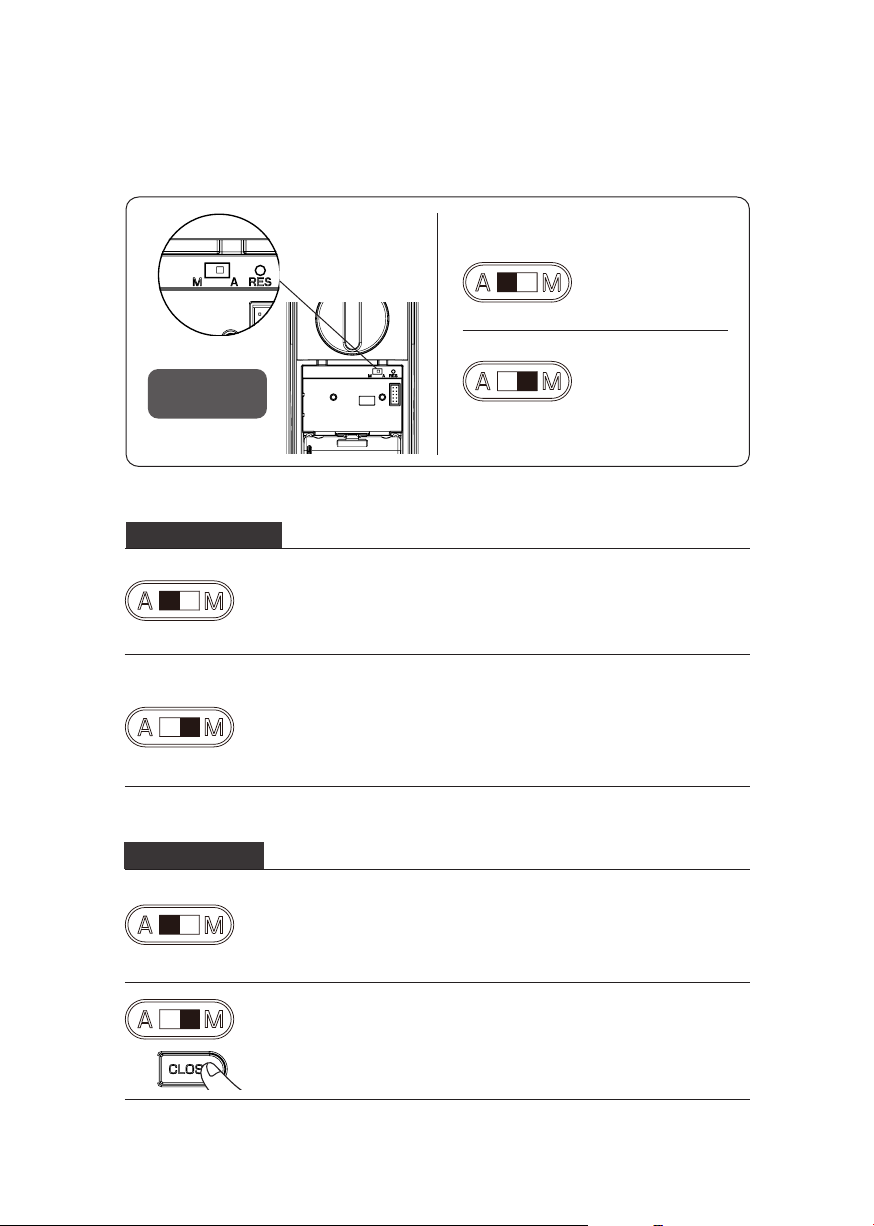
Lock | Auto/Manual Mode
Lock | Auto/
Manual switch
Lock from Outside
When the door is under auto mode, the l atch bolt will be popped
up after closing the door, and there w ill be a voice prompt of “Door
Close”.
When the door is under manual mode, the latch bolt won’t pop
up after closing the door. Only after a successful verication
among a ny of the registered ident ity methods (PIN Code/Key Tag/
Fingerprint), the l atch bolt will pop up, and there will be a voice
prompt of “Door Close”. When it is under manual mode and the door
is closed, wak ing up the out side escutcheon a nd unlock the system
could directly open the door.
[A] indicates auto
mode, after closing
the door, the latch
bolt will pop up, and
the door is lock.
[M] indicates manual
mode, after closing
the door, the latch
bolt will not pop up,
and the door is open.
Lock from Inside
16
When the door is under auto mode, the l atch bolt will be popped
up after closing the door, and there w ill be a voice prompt of “Door
Close”.
When the door is under manual mode, the latch bolt won’t be
popped up after closing the door. Click on [CLOSE] and the latch
bolt will be popped up. After successfully locking the door, the
system will generate a voice prompt of “Door Close”.
Page 19
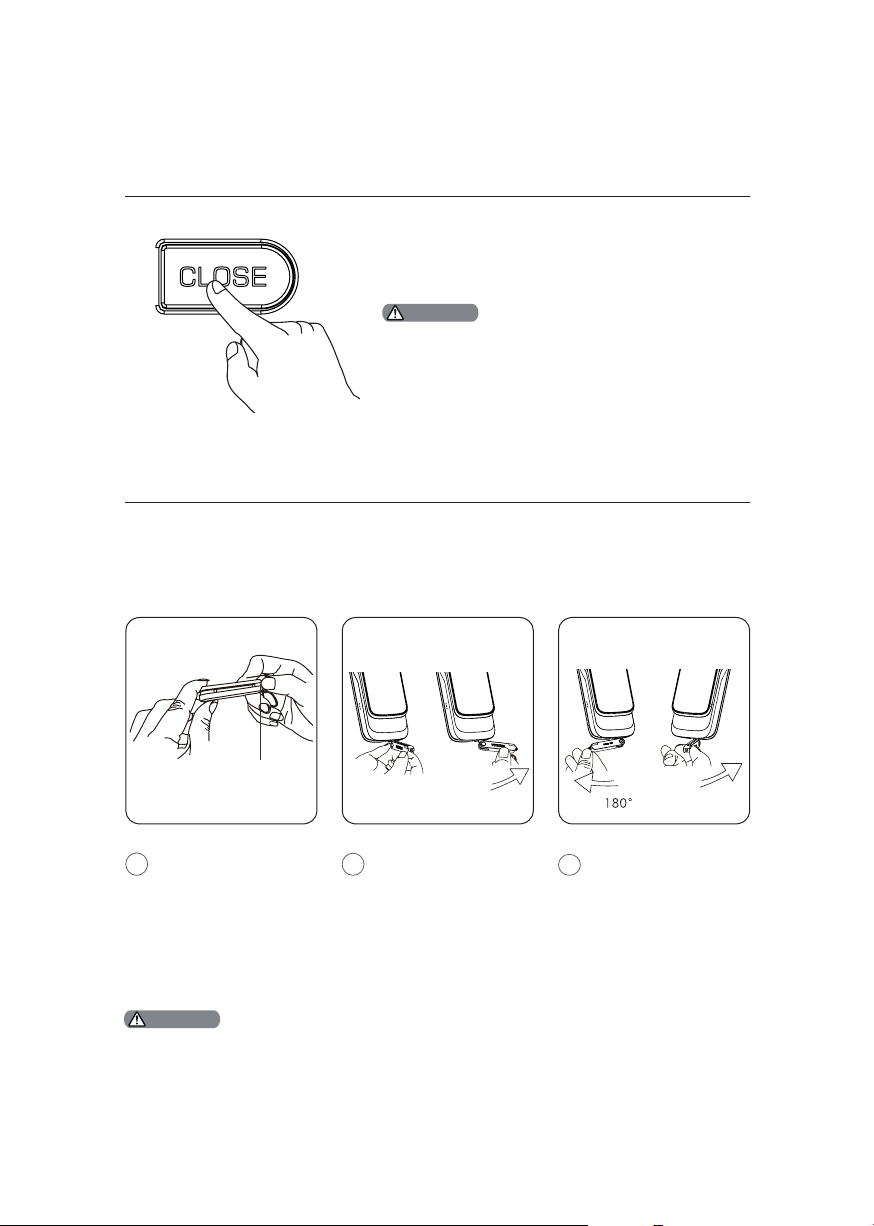
Inside Deadlock
When the EasyKey is locked, long-press the
[CLOSE] button, after the indicator ashes once
in red, and there will be a voice prompt of “Inside
deadlock enabled”.
Attention
Under i nsid e dead lock mo de, all func ti ons of th e
outs ide es cutch eon w ill be locked . If you tr y to wa ke
up the system m anua lly, the keypad area w ill display
the combinat ion of “ 15937(X)” and th ere w ill be a voice
prompt of “Ins ide de adlock enabled” r eminding yo u
that th e door h as been deadlocke d from i nsid e. Under
deadl ock mode, al l oper ations of the outs ide es cutch eon
are disabled. Ma ster PIN code v eri cat ion or mecha nica l
key open ing is re quir ed to releas e the do or from deadlock
mode.
Mechanical Key Opening
Push Button
Cut the box and take
1
out the mechanical
keys. Push the cover
aside and reveal the
key itself.
Attention
It is suggeste d you not t o use the mecha nical key for d aily unlock ing. Use the key f or eme rgencies
only, in ca se the battery i s dead , forge t the PIN code, or the system fails to work pr oper ly.
Inser t the key into
2
the keyhole and keep
the key and key shell
vert ical to each other.
Rotate the key shell
towards the handle for
90°unt il it closes to
the door surface.
Rotate the key shell
3
downwards for 180° to
make it parallel to the
ground. Then rotate it
horizontally towards
the handle to unlock
the door.
17
Page 20
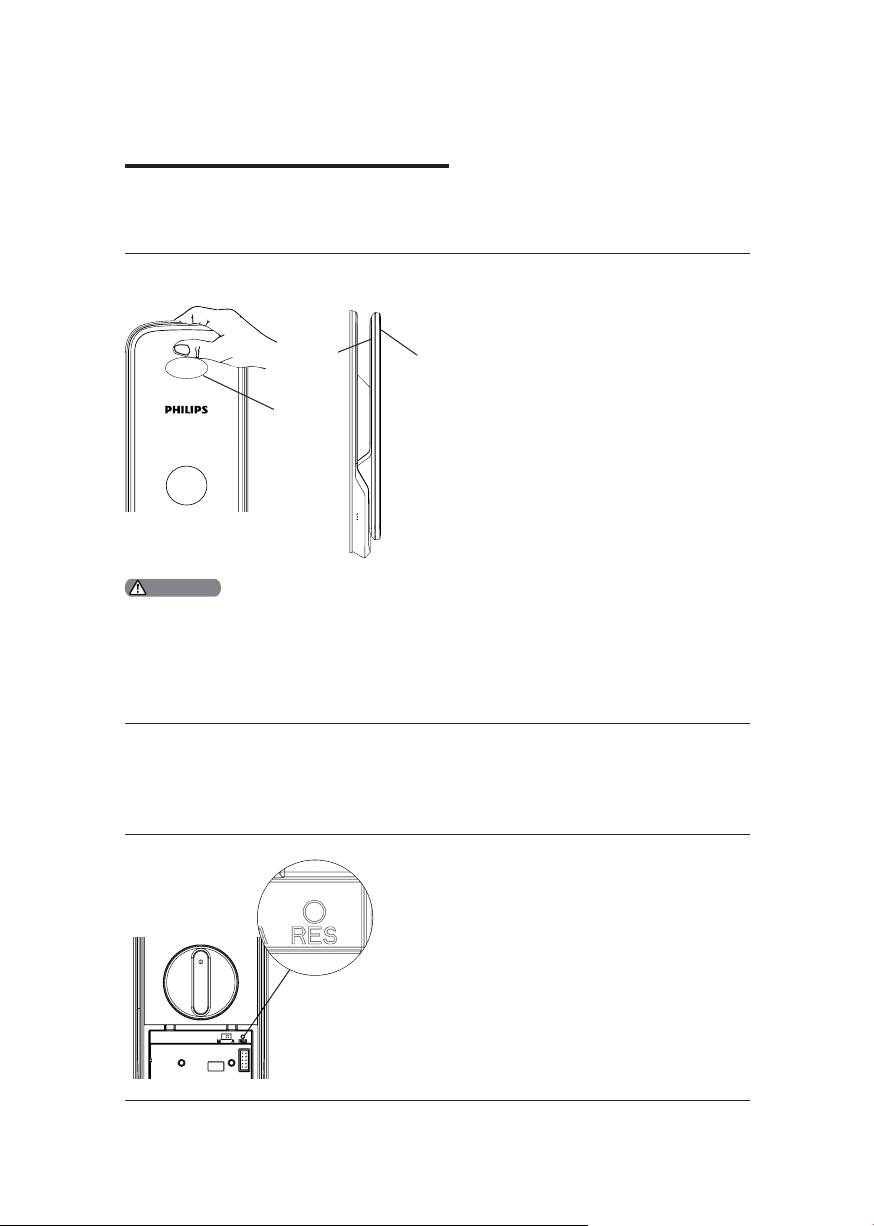
6 Other Functions
Indoor Infrared Sensor Unlocking
Function:
With indoor infrared sensor
Rear
inductive
position
Infrared
Sensor
Attention
When the infra red sensor unlock ing is
disabled, the indoor induct ive unlocking is
inactive. When you touch the front and rea r
of the induct ive position on the handle, the
red light will light up to remind you that the
indoor induc tive unlocking is o.
Front
inductive
position
unlock ing, you could easily
unlock the door from inside.
How to use:
Features with the infrared sensor
on the handle, when the sensor is
triggered, hold the handle’s sensor
modules on both the front and rear
inductive position simultaneously,
you could easily unlock the door.
Enable/Disable:
When the infra red sensor unlock ing
is disabled, long-press the [OPEN]
/ [CLOSE] button at the same t ime
to turn on the function, and the
green light will a sh quickly;
When the infra red sensor unlock ing
is enabled, long-press the [OPEN]
/ [CLOSE] button at the same t ime
to turn o the function and the red
light will ash quickly.
Restore to Default Settings
Functions:
Emptying all user records and restore to default
settings.
How to use:
Double press the [RES] with a sharp object, and
all user records in the system will be emptied, and
the system will restore to default settings.
18
Page 21
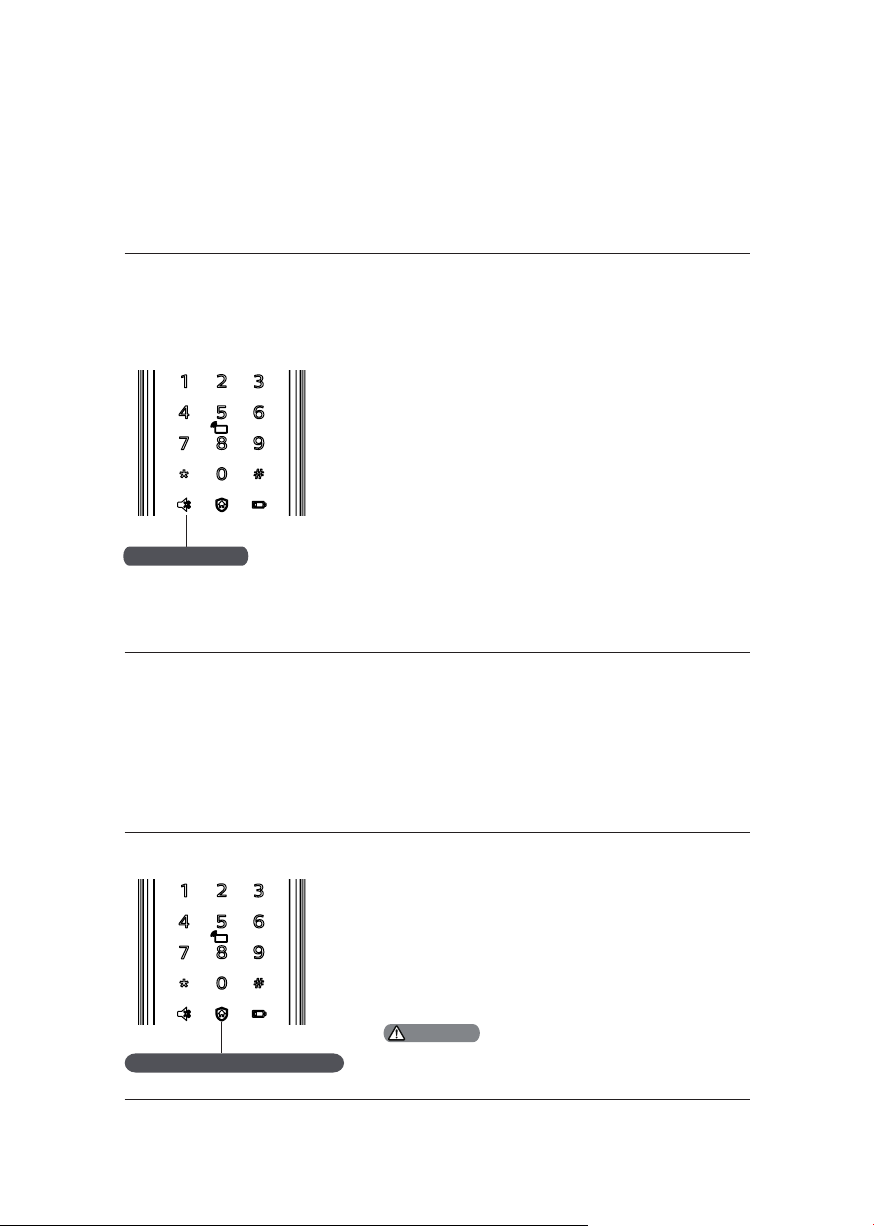
Mute Mode
Functions:
Use only one button to mute the lock by
turning o the voice guide. Applicable to the
scenes where you don’t want to disturb your
famil y.
How to use:
1.Mute:When the system is awake, long-
press the [Mute] button for 2 seconds to
enter one-time mute mode. The button w ill
glow green.
Mute button
2.Unmute:When the system is awake, long-
press the [Mute] button for 2 seconds to
restore the voice guide. The button will glow
white.
Outside Forced Lock
Functions:
Unlock ing from inside will tr igger an al arm.
How to use:
After the door is successfully locked, long-press
the but ton for 2 seconds to enter the outside
forced lock mode.。
Outside forced lock button
Enabl ing the outs ide forced lock func ti on
will n ot aect unlocki ng from outs ide.
Attention
19
Page 22
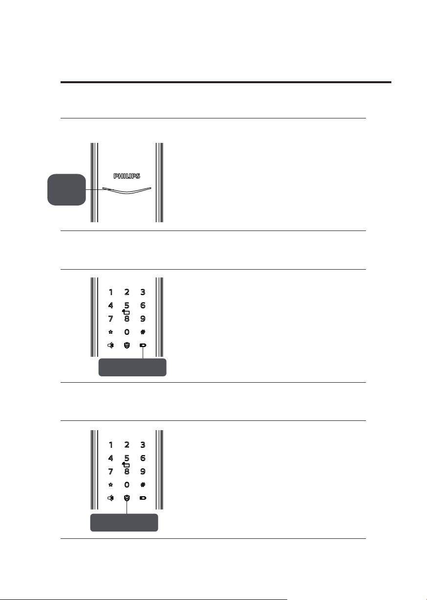
7 The use and meanings of indicators
Lock Status Indicator
The meanings of dierent light colors
Blue: When the system wakes up, the light
will glow blue, indicating that you can
operate the lock.
Lock
status
indicator
Low Battery Voltage Indicator
Low Bat tery
Voltage Indicator
Green: When the door is unlocked, the light
will glow green, indicat ing that the door is
open.
Red: When the door is locked, the light w ill
glow red, indicating that the door is close.
The meanings of dierent light colors
Red:After wak ing up, the system w ill run
an automatic examinat ion of the bat tery
voltage. If the volta ge is too low, the light
will ash in red and there will be a voice
prompt of “Low batter y volt age. Please
replace all batteries”.
Outside Forced Lock Indicator
The meanings of dierent light colors
White:
1.When the door is locked, it will glow in
white, indicating that you can enable the
outside forced lock ing.
2.If you have enabled the outs ide forced
locking, when the system wakes up, the light
will glow in white, indicat ing this function
is in use.
20
Outside forced
lock indicator
Page 23
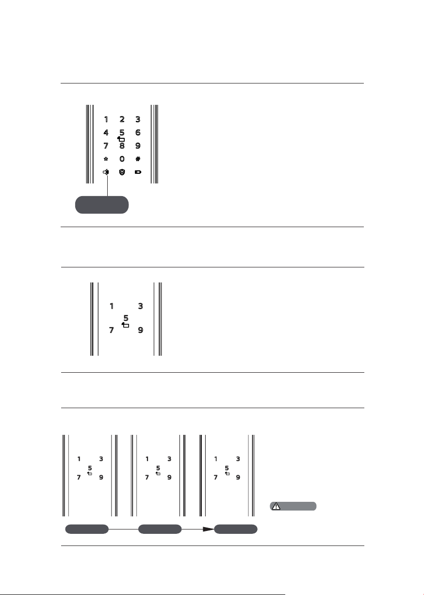
Mute mode indicator
The meanings of dierent light colors
1. White: Indicates the mute mode is o.
2. Green:Indicates the mute mode is on.
Mute mode
indicator
Inside Deadlock Indicator
When the door is under inside deadlocking, the
digital funct ions of the outside escutcheon will
be locked.
If the system wakes up manually, the keypad will
show the combination of “15937 (X)” with a voice
prompt of “ins ide deadlocking enabled”.
System Locked Indicator
3 ashes 2 ashes 1 ash
3 minutes 2 minutes 1 minute
If any of the vericat ion
methods among
ngerprint, password, or
card/key tag has scanned
to be incorrect and the
number of consecutive
incorrect entries reaches
5 times within 5 minutes,
the Ea syKey w ill be
locked for 3 minutes.
Attention
Only under any o f the
veri cat ion method s above
or the key pad is w akened up,
will t he pro mpt be seen.
21
Page 24
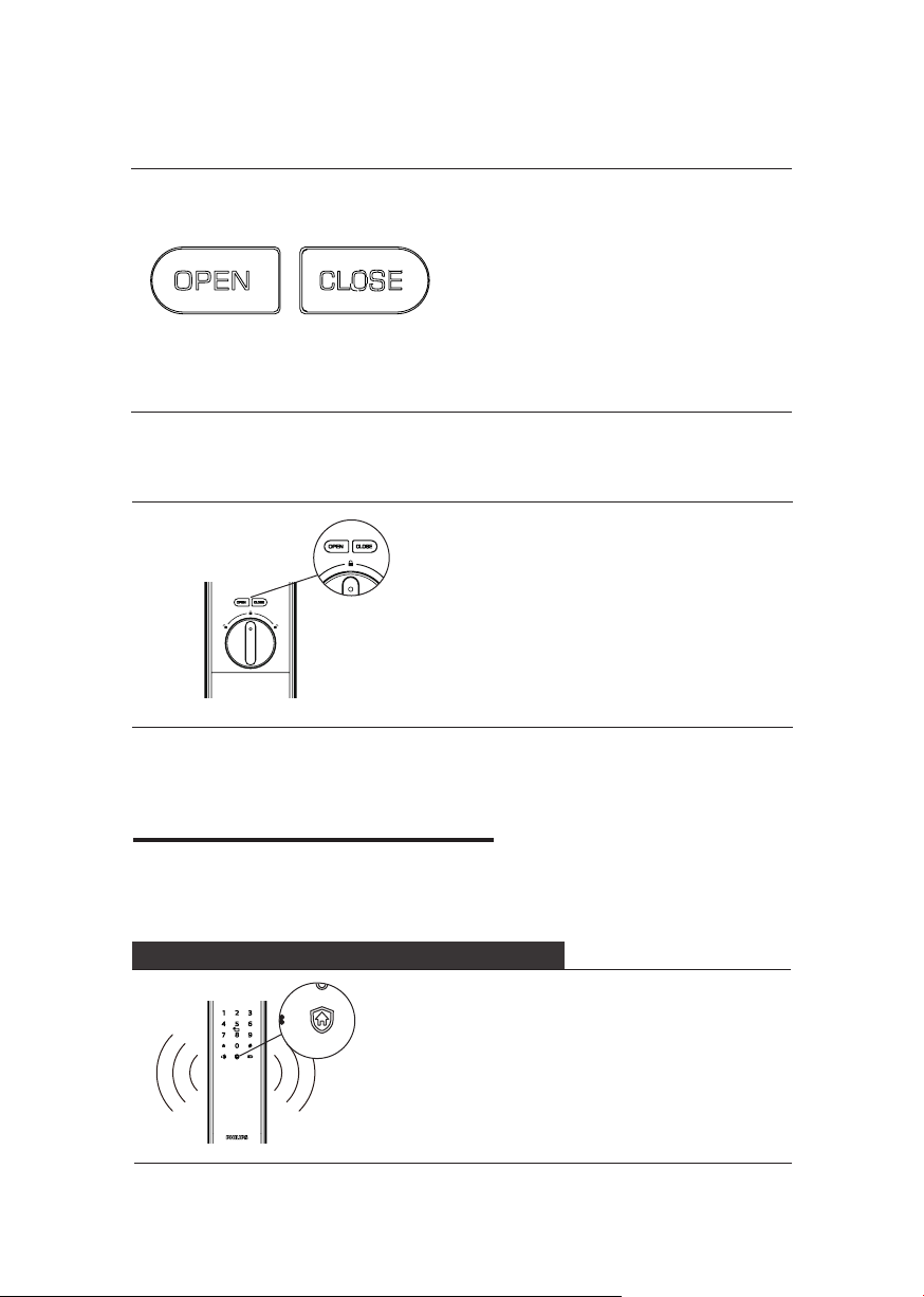
[OPEN/CLOSE] Indicator
The meanings of dierent light colors
1. With 2 ashes in red: indicates
the door is lock ing.
2. With 2 ashes in green: indicates
the door is unlocking.
3. With 1 ash in red: indicates
the door is deadlock ing.
Infrared Sensor Opening Indicator
The meanings of dierent light colors
1.Fast ashing in green: Infrared sensor
opening is on.
2.Fast ashing in red: Infrared sensor
opening is o.
8 Troubleshooting
Alarm Types and Modes
Inside Unlocking Alarm Under Outside Forced Lock
22
Triggering: If the lock is under outside
forced lock mode, unlocking from inside w ill
trigger the alarm.
Alarm mode: Continuously repeated alarms.
Turning o: The alarm can be turned o by
successful verication of any t ype.
Page 25
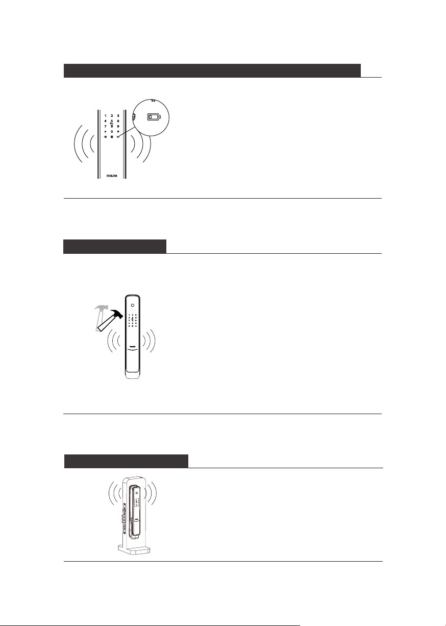
Low Battery Voltage Alarm reminds you of replacing the batteries in t ime
Triggering: After waking up, the system
will run an automat ic examination on the
battery voltage. If the volta ge is too low, the
lock will give an al arm w ith a voice prompt
of “Low battery volt age. Please replace all
batteries”.
Alarm mode: A voice prompt of “Low batter y
voltage. Please replace all batteries” during
unlocking.
Turning o: The alarm will be automatically
turned o.
Anti-dismantling Alarm
Triggering 1: The door is pried open and the
sensor latch bolt pops up.
Alarm mode: Continuously repeated alarms.
Turning o: The alarm can be turned o
automatic ally or by a successful vericat ion.
Triggering 2: The door is pried open and
there is no close t in the door.
Alarm mode: Continuously repeated alarms.
Turning o: The alarm can be turned o
automatic ally, by a successful ver ication
from outside or normal unlocking from
inside.
Deadbolt Abnormality Alarm
Triggering: The deadbolt works abnormally,
fails to lock or unlock the door.
Alarm mode: Continuously repeated alarms.
Turning o: The alarm will be automatically
turned o.
23
Page 26
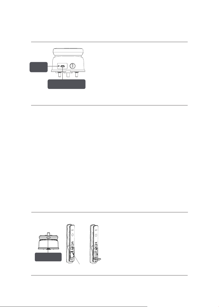
How to apply emergency power supply
When the battery volta ge is insucient,
and the door cannot be opened from
the out side, you can power up the lock
[Reboot]
Button
Emergency Power
Supply Interface
through the Micro USB interface by using
a 5V power bank a s an emergency power
supply. Af ter opening the door, please
replace the batteries immediately.
In case of a system cra sh and it’s
impossible to open the door from outside,
please press the [RES] button and then
relea se it to reboot automatically.
How to replace batteries
Battery Cover
Push Button
Batte ry
Cover Buc kle
24
The lock is powered by four 1.5V alkaline
batteries. There are two sets of working
power stations in the bat tery cabinet. Eight
batteries can put in to extend battery life
and reduce battery replacement frequency.
The bat ter y cabinet locates at the
bottom end of the inside escutcheon.
By pushing the cover upwards, you can
remove it a nd replace the batteries.
Page 27

25
Page 28

Philips and the Philips Shield Emblem are registered trademarks of Koninklijke
Philips N.V. and are used under license. This product has been manufactured by
and is sold under the responsibilit y of Shenzhen Conex Intelligent Technology
Co., Ltd. and Shenzhen Conex Intelligent Technology Co., Ltd. is the warrantor
concerning this product.
 Loading...