

Page 1
Order No. MAC0502032C8
Air Conditioner
CS-E15DB4EW CU-E15DBE
CS-E18DB4EW CU-E18DBE
CS-E21DB4ES CU-E21DBE
CONTENTS
Page Page
1 Features 2
2 Functions
2.1. Remote Control
2.2. Indoor Unit
2.3. Outdoor Unit
3 Product Specifications
3.1. CS-E15DB4EW CU-E15DBE
3.2. CS-E18DB4EW CU-E18DBE
3.3. CS-E21DB4ES CU-E21DBE
4 Dimensions
4.1. Indoor Unit & Remote Control
10
12
12
3
3
4
5
6
6
8
4.2. Outdoor Unit 13
5 Refrigeration Cycle Diagram
6 Block Diagram
7 Wiring Diagram
8 Operation Details
8.1. Basic Operation
8.2. Protection Control Features
9 Operating Instructions
10 Installation And Servicing Air Conditioner Using R410A
10.1. Outline
10.2. Tools For Installing/Servicing Refrigerant Piping
© 2005 Panasonic HA Air-Conditioning (M) Sdn Bhd
(11969-T). All rights reserved. Unauthorized copying
and distribution is a violation of law.
14
15
16
17
17
28
34
42
42
43
Page 2

CS-E15DB4EW CU-E15DBE / CS-E18DB4EW CU-E18DBE / CS-E21DB4ES CU-E21DBE
10.3. Refrigerant Piping Work 47
10.4. Installation, Transferring, Servicing
11 Installation Instructions
11.1. Safety Precautions
11.2. Indoor Unit
11.3. Outdoor Unit
12 Servicing Information
12.1. Troubleshooting
12.2. Breakdown Self Diagnosis Function
12.3. Remote Control
12.4. Auto OFF/ON Button
12.5. Disassembly of Parts
13 Technical Data
13.1. Operation Characteristics
13.2. Sensible Capacity Chart
14 Exploded View (Indoor Unit)
1 Features
Product
•
− Four modes of operation selection
− Powerful Mode operation
− 24-Hour Real Time Timer Control
− Quiet Mode Operation
− Discharged air can be swung automatically or manually
by remote control
− Air filter with function to reduce dust and smoke.
14.1. CS-E15DB4EW CS-E18DB4EW CS-E21DB4ES 79
49
53
53
55
62
66
66
68
70
71
72
75
75
78
79
14.2. CZ-BT20E (Front Grille Complete)
15 Replacemen t Parts List (Indoor Unit)
15.1. CS-E15DB4EW CS-E18DB4EW CS-E21DB4ES
15.2. CZ-BT20E (Front Grille Complete)
16 Exploded View (Outdoor Unit)
16.1. CU-E15DBE CU-E18DBE CU-E21DBE
17 Replacemen t Parts List (Outdoor Unit)
17.1. CU-E15DBE CU-E18DBE CU-E21DBE
18 Electronic Circuit Diagram
18.1. Indoor Unit
18.2. Outdoor Unit
18.3. Remote Control
18.4. Print PatternIndoor Unit Printed Circuit Board
18.5. Print PatternOutdoor Unit Printed Circuit Board View
Serviceability Improvement
•
− Removable and washable Intake Grille
− Breakdown Self Diagnosis function
Environmental Protection
•
− Non-ozone-depletion substances refrigerant (R410A)
Quality Improvement
•
− Gas leakage detection
− Deice operation
− Auto restart control
81
82
82
83
84
84
85
85
86
86
90
95
96
97
2
Page 3
2 Functions
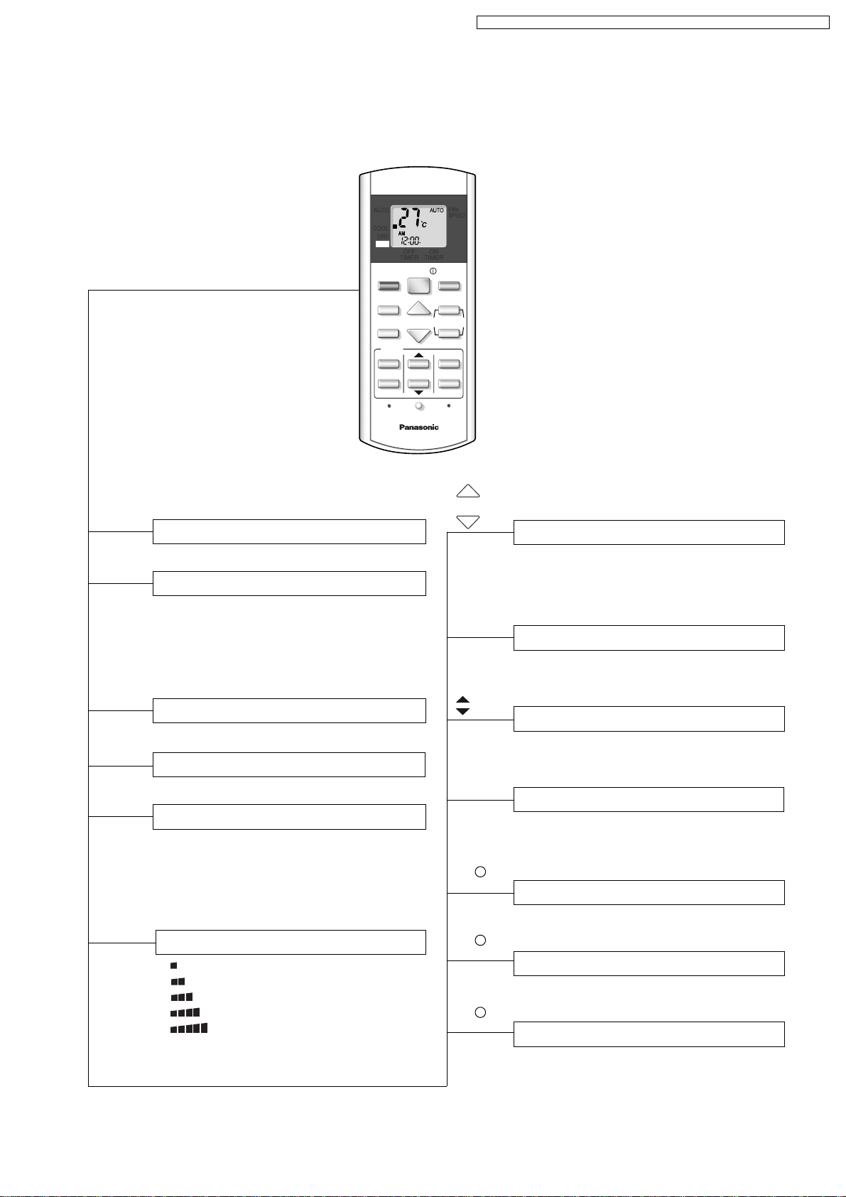
2.1. Remote Control
CS-E15DB4EW CU-E15DBE / CS-E18DB4EW CU-E18DBE / CS-E21DB4ES CU-E21DBE
OFF / ON I
MODE
Operation OFF / ON
Operation Mode Selection
•
•
•
•
AUTO
HEAT
COOL
DRY
Automatic Operation
Heating Operation
Cooling Operation
Soft Dry Operation
AUTO
HEAT
COOL
DRY
OFF
OFF
TIMERONTIMER
OFF/ON
MODE
POWERFUL
QUIET
TIMER
ON
123
OFF
CHECK
TEMP
CLOCK RESET
INVENTER
FAN SPEED
AIR SWING
CANCEL
CANCEL
FAN
SPEED
AUTO
MANUAL
SET
TEMP
TIMER-ON
TIMER-OFF
Room Temperature Setting
• Increase or decrease set temperature.
(16°C to 30°C)
Timer Setting
• 24-hour, OFF / ON Real Timer Setting.
POWERFUL
QUIET
AIR SWING
FAN SPEED
Powerful Mode Operation
Quiet Mode Operation
Airflow Direction Control
•
AUTO
Vertical Automatic Airflow
Direction Control.
MANUAL
•
Vertical Manual Airflow
Direction Control.
Indoor Fan Speed Selection
• Low
•
•
•
•
•
AUTO
MediumMedium
Medium+
High
Automatic Fan Speed
SET
CANCEL
CLOCK
CHECK
RESET
Time / Timer Setting
• Hours and minutes setting.
Timer Operation Set / Cancel
• ON Timer and OFF Timer setting and
cancellation.
Clock Setting
• Current time setting.
Check Point
• Breakdown self diagnosis function.
Reset Point
• Clear memory data.
3
Page 4
CS-E15DB4EW CU-E15DBE / CS-E18DB4EW CU-E18DBE / CS-E21DB4ES CU-E21DBE
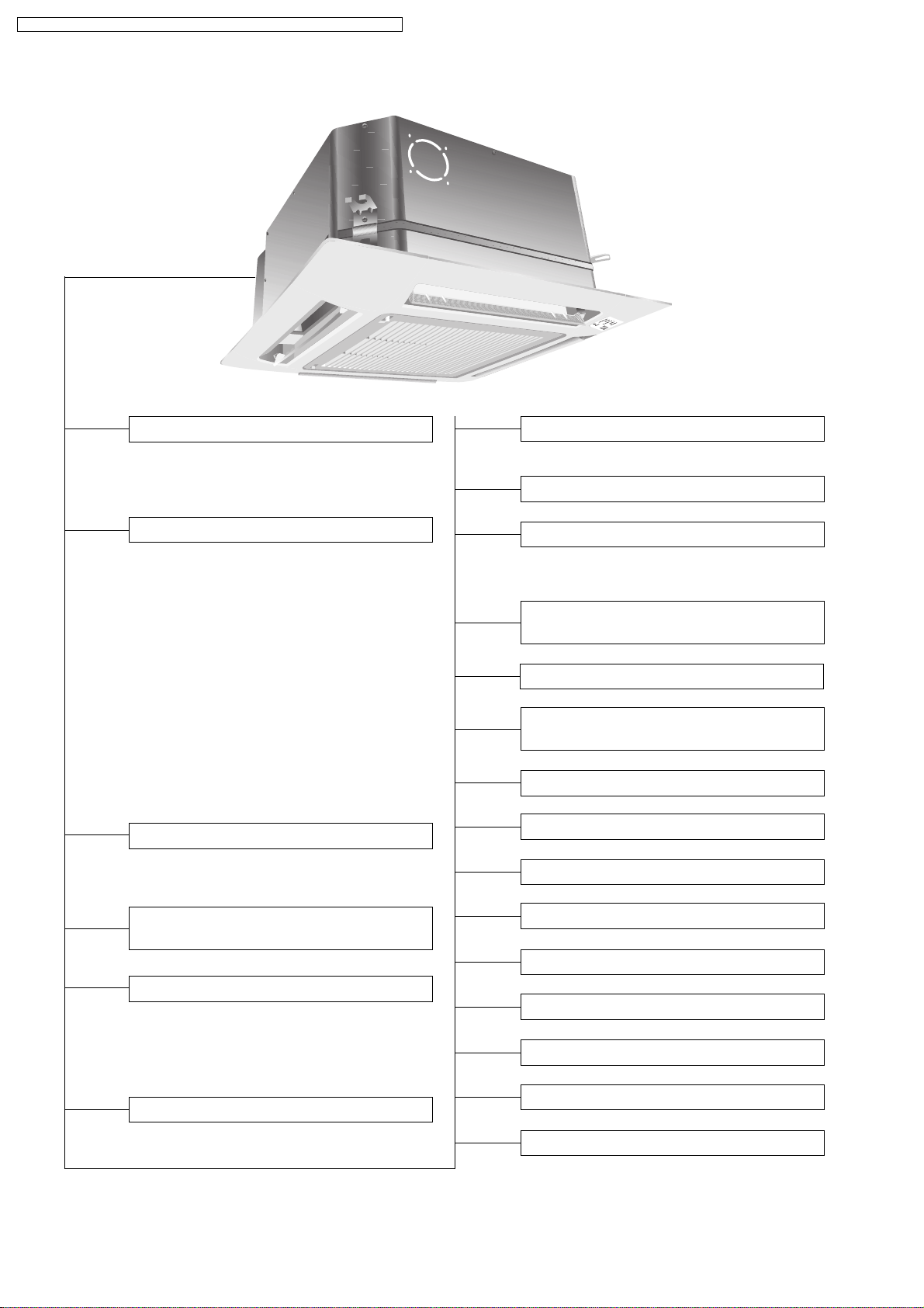
2.2. Indoor Unit
Automatic Operation Switch
• To run automatic operation, force cooling or
heating operation, or change remote control
signal type.
Operation Indication Lamps (LED)
•
POWER
•
TIMER
•
QUIET
•
POWERFUL
•
AIR SWING
(Green)........Lights up in operation,
blinks in Automatic
Operation Mode judging,
deice, On Timer sampling
and Hot Start operation.
(Orange)......Lights up in Timer Setting.
Blinks in Self Diagnosis
Control.
(Orange)......Lights up in Quiet Mode
Operation.
(Orange) ... Lights up when Powerful
Mode is selected.
(Orange).... Lights up in Auto Air
Swing.
Four Operation Modes
• Automatic, Heating, Cooling and Soft Dry
Operation.
Quiet Mode
• To provide quiet operation.
24-Hour Real Time Timer Control
Automatic Restart Control
• Operation is restarted after power failure at
previous setting mode.
Microcomputer-controlled Room
Temperature Control
Breakdown Self Diagnosis Function
Low Pressure Control
(Gas Leakeage Detection)
Indoor Power Relay Control
Anti-Dew Formation Control
Anti Freezing Control
Automatic and 5 Manual Indoor
Fan Speeds
Airflow Direction Control
• Vertical discharged air can be swung
automatically or manually by remote control.
• Horizontal discharged air can be adjusted by
hand.
Powerful Mode
• For quick cooling or heating.
Anti-Cold Draft Control
Hot Start
Intake Air Temperature Control
High Pressure Control
Deodorizing Control
Deice Operation
4
Page 5
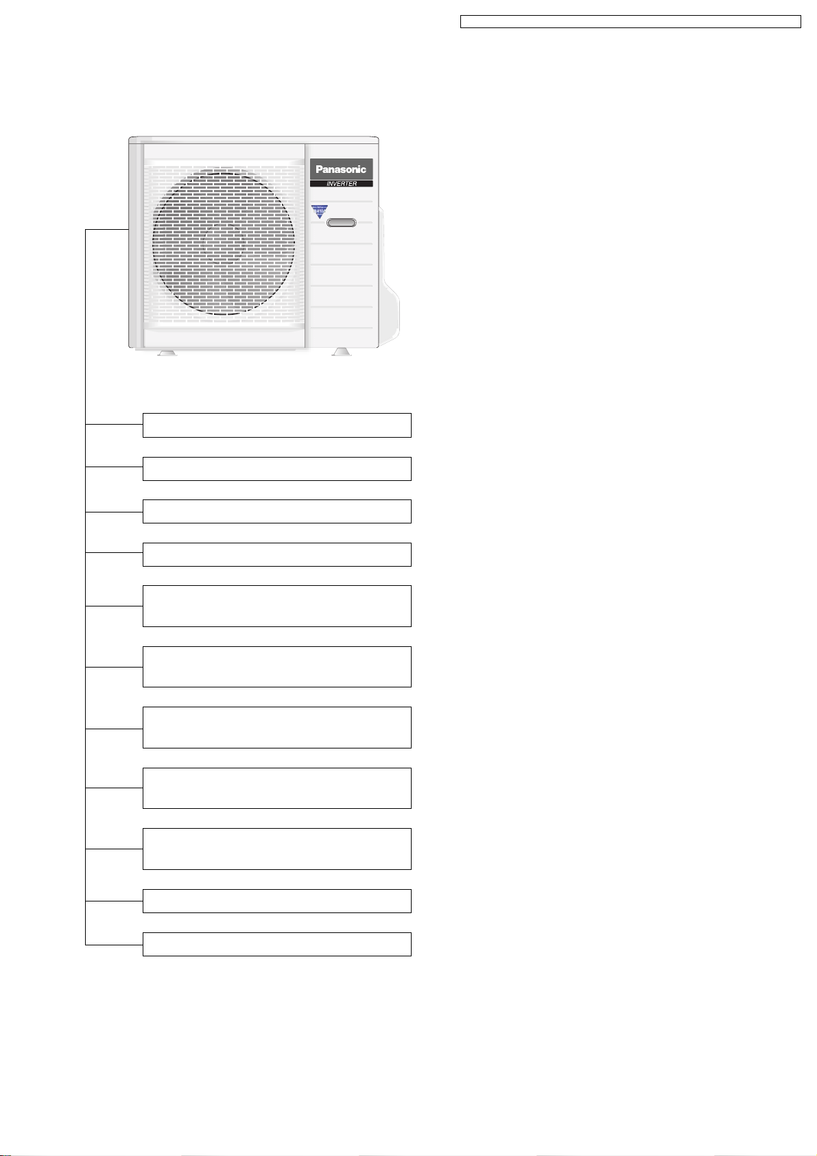
2.3. Outdoor Unit
CS-E15DB4EW CU-E15DBE / CS-E18DB4EW CU-E18DBE / CS-E21DB4ES CU-E21DBE
Time Delay Safety Control
30 seconds Forced Operation
Overload Protection Control
Total Running Current Control
Compressor Overheating
Prevention Control
IPM (Power Transistor)
Overheating Protection Control
Low Operation Frequency
Protection Control
Mininum Operation Frequency
Protection Control
Outdoor Air Temperature
Control
Standby Control
Deice Operation
5
Page 6
CS-E15DB4EW CU-E15DBE / CS-E18DB4EW CU-E18DBE / CS-E21DB4ES CU-E21DBE
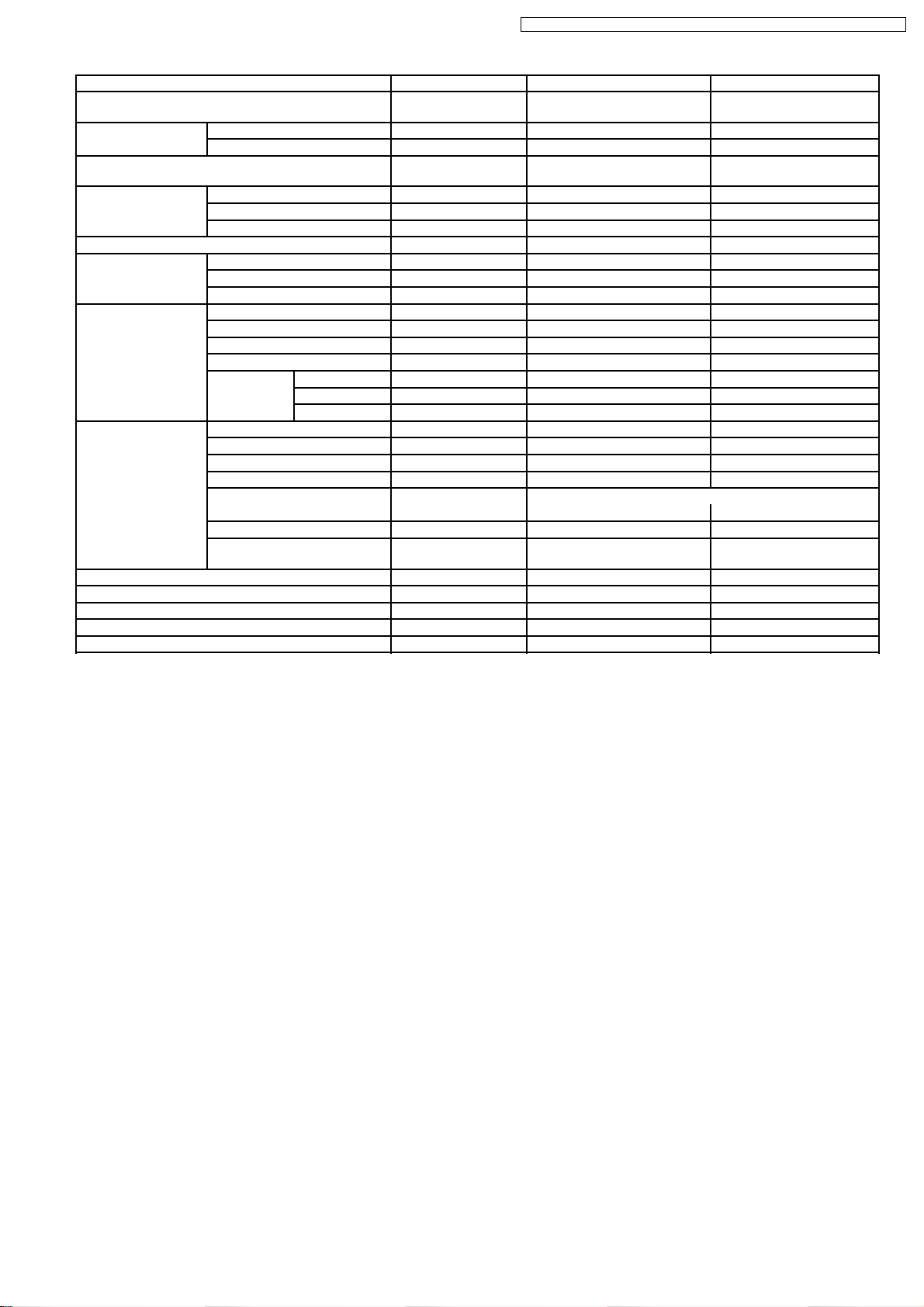
3 Product Specifications
3.1. CS-E15DB4EW CU-E15DBE
Unit CS-E15DB4EW CU-E15DBE
Cooling Capacity kW
kcal/h
BTU/h
Heating Capacity kW
kcal/h
BTU/h
Moisture Removal l/h
Pint/h
Power Source (Phase, Voltage, Cycle) ø
V
Hz
Airflow Method OUTLET
INTAKE
4.10 (0.90 - 4.80)
3,530 (770 - 4,130)
14,000 (3,070 - 16,400)
5.10 (0.90 - 6.20)
4,390 (770 - 5,330)
17,400 (3,070 - 21,100)
2.3
(4.9)
Single
230 - 240
50
SIDE VIEW TOP VIEW
Air Volume Lo m3/min (cfm) Cooling; 7.5 (260) —
Heating; 9.0 (320)
Me m3/min (cfm) Cooling; 9.0 (320) —
Heating; 10.1 (360)
Hi m3/min (cfm) Cooling; 10.5 (370) Cooling; 46.8 (1,650)
Heating; 10.8 (380) Heating; 48.5 (1,710)
dB (A) Cooling; High 34, Low 26 Cooling; 45
Heating; High 35, Low 28 Heating; 47
Noise Level
Power level dB Cooling; High 47 Cooling; High 58
Heating; High 48 Heating; High 60
Electrical Data Input Power W Cooling; 1,300 (255 - 1,710)
Heating; 1,770 (260 - 2,180)
Running Current A Cooling; 6.0 - 5.9
Heating; 8.0 - 7.9
Piping Connection Port
(Flare piping)
EER W/W Cooling; 3.15 (3.53 - 2.81)
BTU/hW Cooling; 10.8 (12.0 - 9.6)
COP W/W Heating; 2.88 (3.46 - 2.84)
BTU/hW Heating; 9.8 (11.8 - 9.7)
Starting Current A 8.0
inch
inch
G ; Half Union 1/2”
L ; Half Union 1/4”
G ; 3-way valve 1/2”
L ; 2-way valve 1/4”
6
Page 7
CS-E15DB4EW CU-E15DBE / CS-E18DB4EW CU-E18DBE / CS-E21DB4ES CU-E21DBE
Unit CS-E15DB4EW CU-E15DBE
Pipe Size
(Flare piping)
Drain
Hose
Power Cord Length
Number of core-wire
Dimensions Height inch (mm) 10 - 1/4 (260) 29 - 17/32 (750)
Net Weight lb (kg) 40 (18) 106 (48)
Compressor Type — Involute scroll
Air Circulation Type Backward Fan Propeller Fan
Heat Exchanger Description Evaporator Condenser
Refrigerant Control Device — Expansion Valve
Refrigeration Oil (cm3) — RB68A (400)
Refrigerant (R410A) kg (oz) — 1.23 (43.4)
Thermostat Electronic Control —
Protection Device Electronic Control Electronic Control
Inner diameter mm 30 —
Length m 0.193 —
Width inch (mm) 22 - 5/8 (575) 34 - 7/16 (875)
Depth inch (mm) 22 - 5/8 (575) 13 - 19/32 (345)
Motor Type — Brushless (4-pole)
Rated Output W — 900
Material ABS + GF 10% P.P
Motor Type DC Brushless Motor (8-poles) Transistor (8-poles)
Rate Output W 40 40
Fan Speed Lo (Cool/Heat) rpm 400 / 480 —
Me (Cool/Heat) rpm 480 / 540 —
Hi (Cool/Heat) rpm 560 / 600 640 / 660
Tube material Copper Copper
Fin material Aluminium (Pre Coat) Aluminium
Fin Type Slit Fin Corrugated Fin
Row / Stage (Plate fin configuration, forced draft)
FPI 18 18
Size (W × H × L) mm 1,330
inch
inch
G (gas side) ; 1/2”
L (liquid side) ; 1/4”
—— —
2/10 1/28
× 210 × 25.4 871.7 × 711.2 × 22
1,270
G (gas side) ; 1/2”
L (liquid side) ; 1/4”
—
•
Specifications are subjected to change without notice for further improvement.
7
Page 8

CS-E15DB4EW CU-E15DBE / CS-E18DB4EW CU-E18DBE / CS-E21DB4ES CU-E21DBE
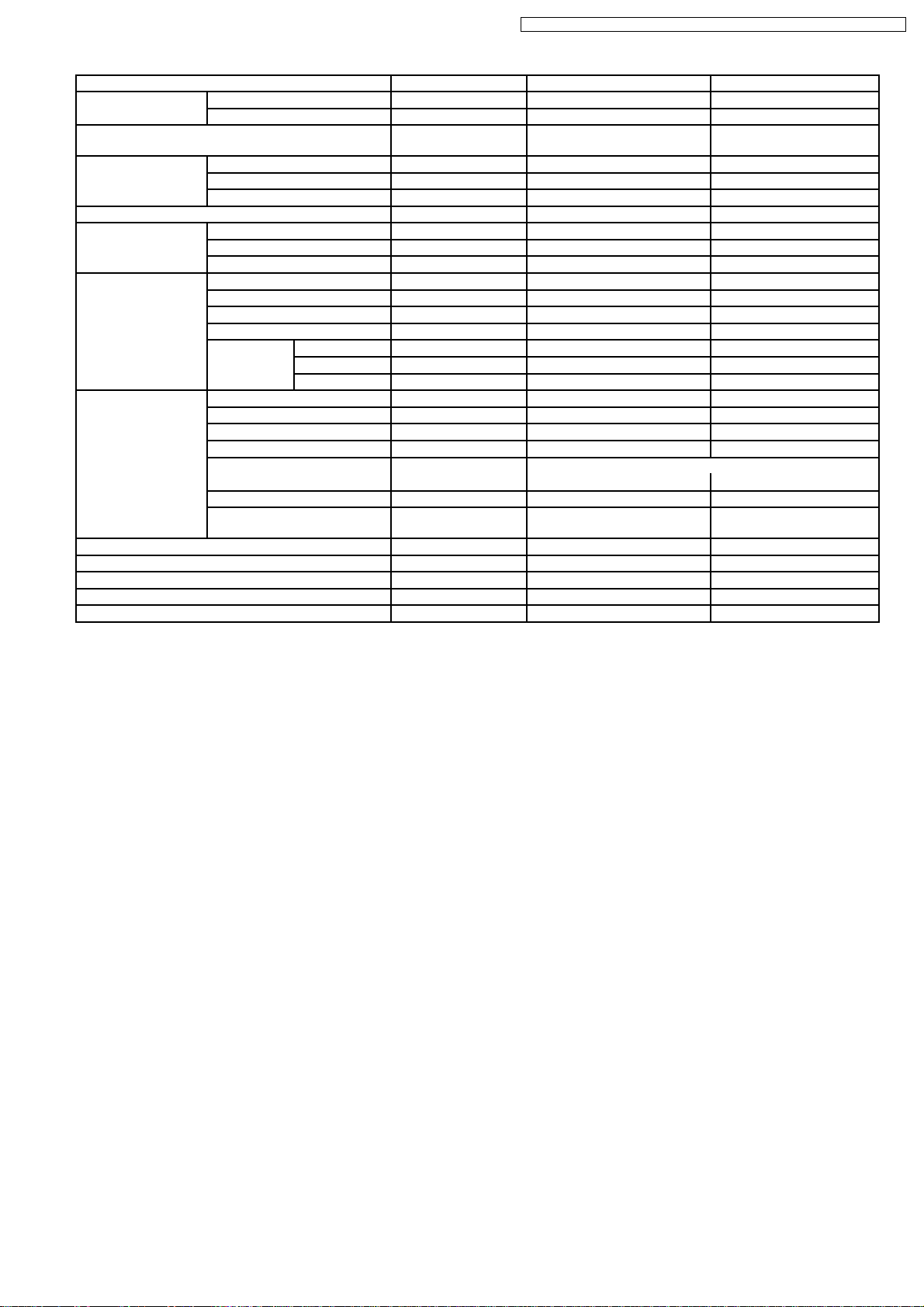
3.2. CS-E18DB4EW CU-E18DBE
Unit CS-E18DB4EW CU-E18DBE
Cooling Capacity kW
kcal/h
BTU/h
Heating Capacity kW
kcal/h
BTU/h
Moisture Removal l/h
Pint/h
Power Source (Phase, Voltage, Cycle) ø
V
Hz
Airflow Method OUTLET
INTAKE
4.80 (0.90 - 5.70)
4,130 (770 - 4,900)
16,400 (3,070 - 19,400)
5.60 (0.90 - 7.10)
4,820 (770 - 6,110)
19,100 (3,070 - 24,200)
2.6
(5.5)
Single
230 - 240
50
SIDE VIEW TOP VIEW
Air Volume Lo m3/min (cfm) Cooling; 8.0 (280) —
Heating; 9.1 (320)
Me m3/min (cfm) Cooling; 9.5 (340) —
Heating; 10.4 (370)
Hi m3/min (cfm) Cooling; 11.0 (390) 40.0 (1,410)
Heating; 11.5 (405)
dB (A) Cooling; High 36, Low 28 Cooling; 47
Heating; High 37, Low 29 Heating; 48
Noise Level
Power level dB Cooling; High 49 Cooling; High 60
Heating; High 50 Heating; High 61
Electrical Data Input Power W Cooling; 1,530 (255 - 1,930)
Heating; 1,900 (260 - 2,450)
Running Current A Cooling; 7.0 - 6.9
Heating; 8.5 - 8.3
Piping Connection Port
(Flare piping)
Pipe Size
(Flare piping)
EER W/W Cooling; 3.14 (3.53 - 2.95)
BTU/hW Cooling; 10.7 (12.0 - 10.1)
COP W/W Heating; 2.95 (3.46 - 2.90)
BTU/hW Heating; 10.1 (11.8 - 9.9)
Starting Current A 8.5
inch
inch
inch
inch
G ; Half Union 1/2”
L ; Half Union 1/4”
G (gas side) ; 1/2”
L (liquid side) ; 1/4”
G ; 3-way valve 1/2”
L ; 2-way valve 1/4”
G (gas side) ; 1/2”
L (liquid side) ; 1/4”
8
Page 9
CS-E15DB4EW CU-E15DBE / CS-E18DB4EW CU-E18DBE / CS-E21DB4ES CU-E21DBE
Unit CS-E18DB4EW CU-E18DBE
Drain
Hose
Power Cord Length
Number of core-wire
Dimensions Height inch (mm) 10 - 1/4 (260) 29 - 17/32 (750)
Net Weight lb (kg) 40 (18) 106 (48)
Compressor Type — Involute scroll
Air Circulation Type Backward Fan Propeller Fan
Heat Exchanger Description Evaporator Condenser
Refrigerant Control Device — Expansion Valve
Refrigeration Oil (cm3) — RB68A (400)
Refrigerant (R410A) kg (oz) — 1.06 (37.4)
Thermostat Electronic Control —
Protection Device Electronic Control Electronic Control
Inner diameter mm 30 —
Length m 0.193 —
—— —
Width inch (mm) 22 - 5/8 (575) 34 - 7/16 (875)
Depth inch (mm) 22 - 5/8 (575) 13 - 19/32 (345)
Motor Type — Brushless (4-pole)
Rated Output W — 900
Material ABS + GF 10% P.P
Motor Type DC Brushless Motor (8-poles) Transistor (8-poles)
Rate Output W 40 40
Fan Speed Lo (Cool/Heat) rpm 430 / 490 —
Me (Cool/Heat) rpm 510 / 560 —
Hi (Cool/Heat) rpm 590 / 640 660 / 660
Tube material Copper Copper
Fin material Aluminium (Pre Coat) Aluminium
Fin Type Slit Fin Corrugated Fin
Row / Stage (Plate fin configuration, forced draft)
2/10 2/34
FPI 18 16
Size (W × H × L) mm 1,330
× 210 × 25.4 849.3
1,270
—
× 714 × 36.4
878
•
Specifications are subjected to change without notice for further improvement.
9
Page 10
CS-E15DB4EW CU-E15DBE / CS-E18DB4EW CU-E18DBE / CS-E21DB4ES CU-E21DBE
3.3. CS-E21DB4ES CU-E21DBE
Unit CS-E21DB4ES CU-E21DBE
Cooling Capacity kW
kcal/h
BTU/h
Heating Capacity kW
kcal/h
BTU/h
Moisture Removal l/h
Pint/h
Power Source (Phase, Voltage, Cycle) ø
V
Hz
Airflow Method OUTLET
INTAKE
5.90 (0.90 - 6.30)
5,070 (770 - 5,420)
20,100 (3,070 - 21,500)
7.00 (0.90 - 8.00)
6,020 (770 - 6,880)
23,900 (3,070 - 27,300)
3.3
(7.0)
Single
230 - 240
50
SIDE VIEW TOP VIEW
Air Volume Lo m3/min (cfm) Cooling; 9.3 (330) —
Heating; 10.6 (370)
Me m3/min (cfm) Cooling; 11.0 (390) —
Heating; 12.3 (430)
Hi m3/min (cfm) Cooling; 12.8 (450) Cooling; 42.8 (1,510)
Heating; 14.0 (495) Heating; 41.5 (1,460)
dB (A) Cooling; High 41, Low 33 Cooling; 49
Heating; High 42, Low 34 Heating; 49
Noise Level
Power level dB Cooling; High 54 Cooling; High 62
Heating; High 55 Heating; High 62
Electrical Data Input Power W Cooling; 2,050 (255 - 2,200)
Heating; 2,450 (260 - 2,820)
Running Current A Cooling; 9.2 - 9.0
Heating; 10.9 - 10.6
Piping Connection Port
(Flare piping)
Pipe Size
(Flare piping)
EER W/W Cooling; 2.88 (3.53 - 2.86)
BTU/hW Cooling; 9.8 (12.0 - 9.8)
COP W/W Heating; 2.86 (3.46 - 2.84)
BTU/hW Heating; 9.8 (11.8 - 9.7)
Starting Current A 10.9
inch
inch
inch
inch
G ; Half Union 1/2”
L ; Half Union 1/4”
G (gas side) ; 1/2”
L (liquid side) ; 1/4”
G ; 3-way valve 1/2”
L ; 2-way valve 1/4”
G (gas side) ; 1/2”
L (liquid side) ; 1/4”
10
Page 11

CS-E15DB4EW CU-E15DBE / CS-E18DB4EW CU-E18DBE / CS-E21DB4ES CU-E21DBE
Unit CS-E21DB4ES CU-E21DBE
Drain
Hose
Power Cord Length
Number of core-wire
Dimensions Height inch (mm) 10 - 1/4 (260) 29 - 17/32 (750)
Net Weight lb (kg) 40 (18) 108 (49)
Compressor Type — Involute scroll
Air Circulation Type Backward Fan Propeller Fan
Heat Exchanger Description Evaporator Condenser
Refrigerant Control Device — Expansion Valve
Refrigeration Oil (cm3) — RB68A (400)
Refrigerant (R410A) kg (oz) — 1.15 (40.6)
Thermostat Electronic Control —
Protection Device Electronic Control Electronic Control
Inner diameter mm 30 —
Length m 0.193 —
—— —
Width inch (mm) 22 - 5/8 (575) 34 - 7/16 (875)
Depth inch (mm) 22 - 5/8 (575) 13 - 19/32 (345)
Motor Type — Brushless (4-pole)
Rated Output W — 900
Material ABS + GF 10% P.P
Motor Type DC Brushless Motor (8-poles) Transistor (8-poles)
Rate Output W 40 40
Fan Speed Lo (Cool/Heat) rpm 510 / 580 —
Me (Cool/Heat) rpm 600 / 670 —
Hi (Cool/Heat) rpm 700 / 770 700 / 680
Tube material Copper Copper
Fin material Aluminium (Pre Coat) Aluminium
Fin Type Slit Fin Corrugated Fin
Row / Stage (Plate fin configuration, forced draft)
2/10 2/34
FPI 18 18
Size (W × H × L) mm 1,330
× 210 × 25.4 839.5
1,270
—
× 714 × 36.4
868
•
Specifications are subjected to change without notice for further improvement.
11
Page 12
CS-E15DB4EW CU-E15DBE / CS-E18DB4EW CU-E18DBE / CS-E21DB4ES CU-E21DBE
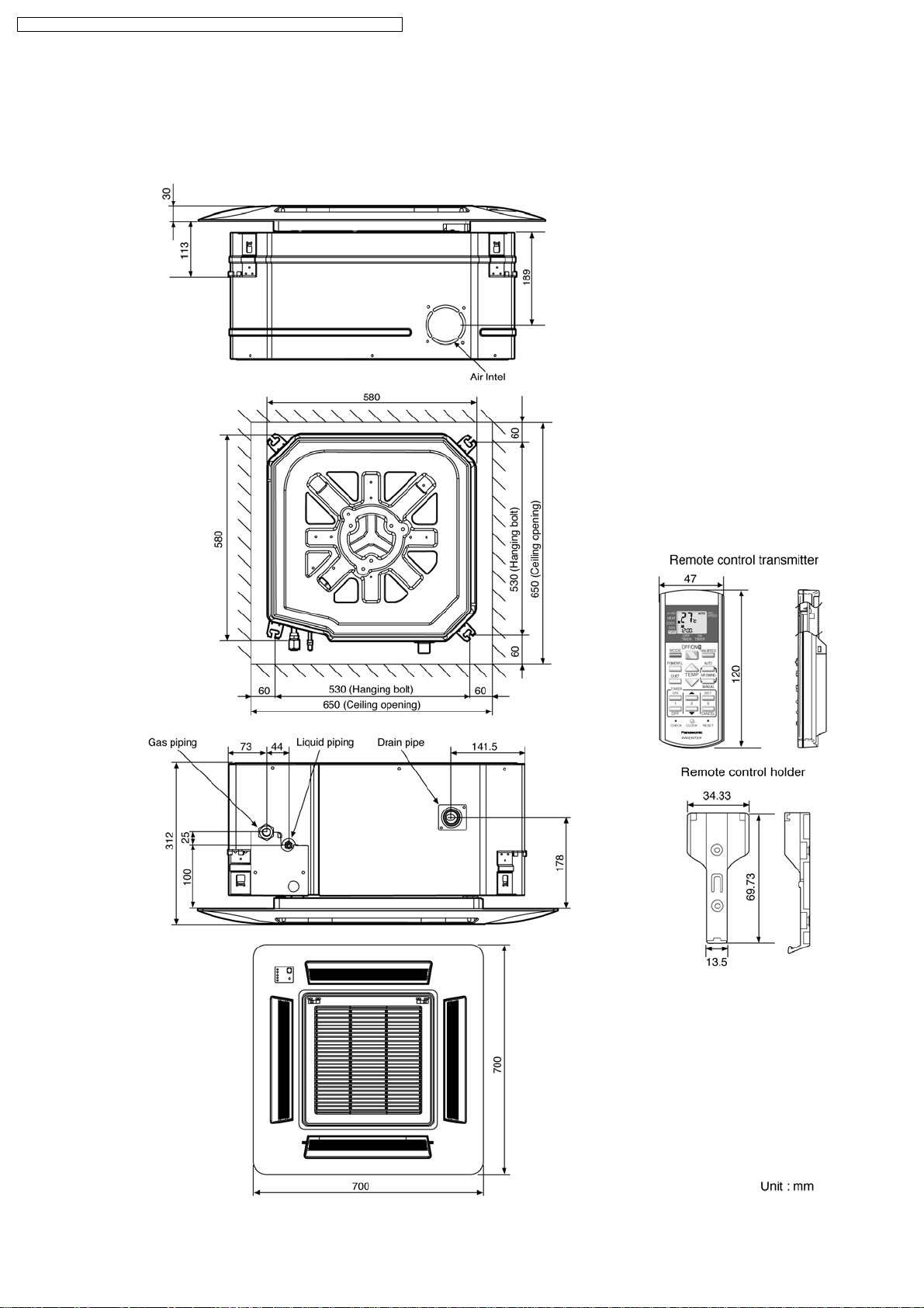
4 Dimensions
4.1. Indoor Unit & Remote Control
4.1.1. CS-E15DB4EW CS-E18DB4EW CS-E21DB4ES
12
Page 13
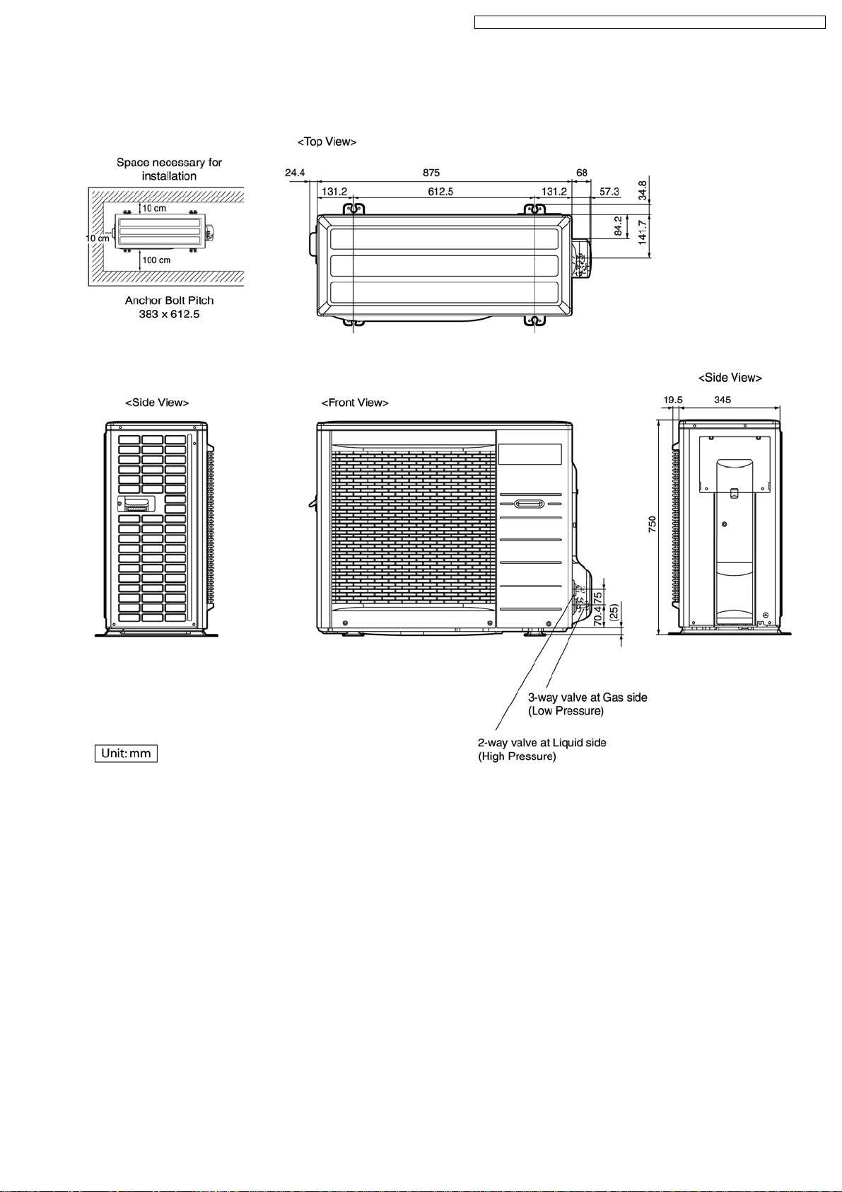
4.2. Outdoor Unit
4.2.1. CU-E15DBE CU-E18DBE CU-E21DBE
CS-E15DB4EW CU-E15DBE / CS-E18DB4EW CU-E18DBE / CS-E21DB4ES CU-E21DBE
13
Page 14
CS-E15DB4EW CU-E15DBE / CS-E18DB4EW CU-E18DBE / CS-E21DB4ES CU-E21DBE
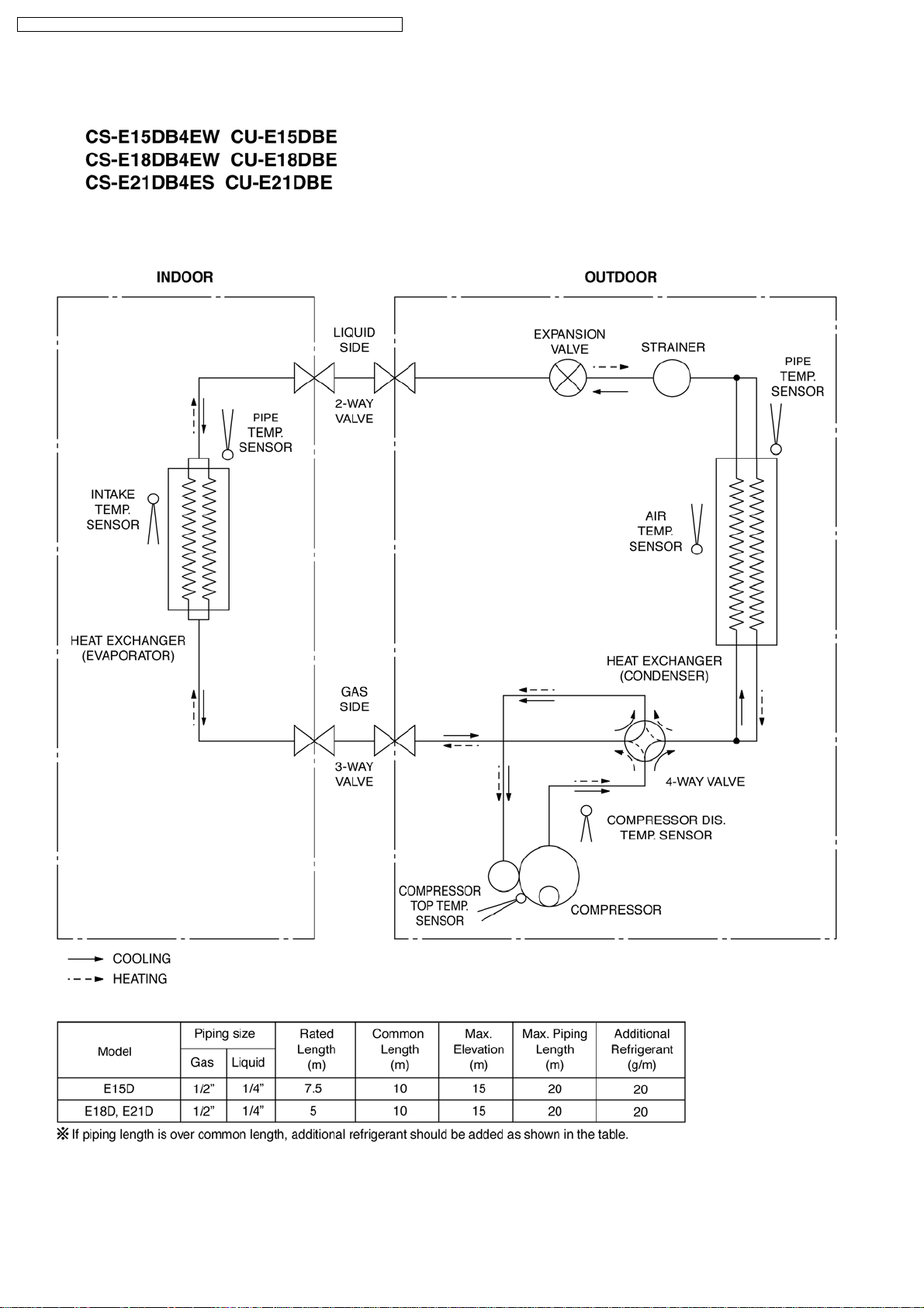
5 Refrigeration Cycle Diagram
14
Page 15
6 Block Diagram
CS-E15DB4EW CU-E15DBE / CS-E18DB4EW CU-E18DBE / CS-E21DB4ES CU-E21DBE
15
Page 16
CS-E15DB4EW CU-E15DBE / CS-E18DB4EW CU-E18DBE / CS-E21DB4ES CU-E21DBE
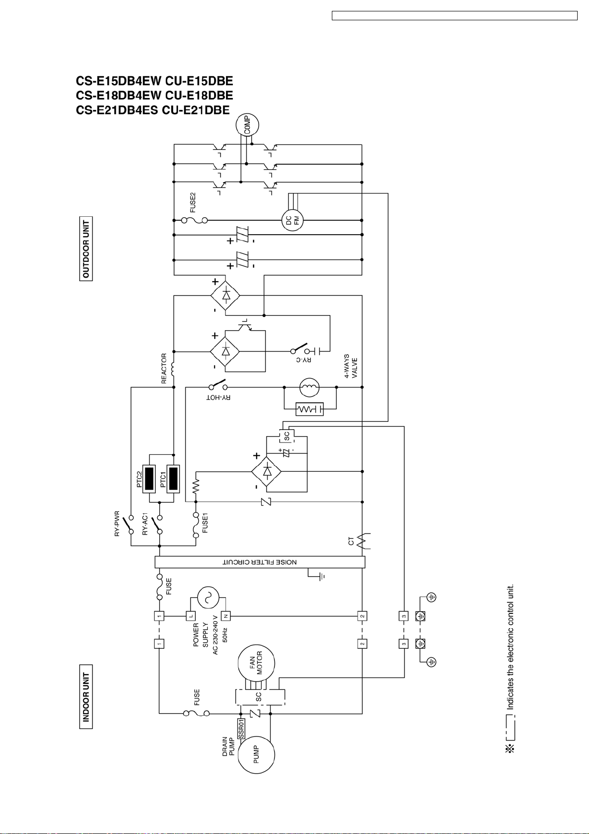
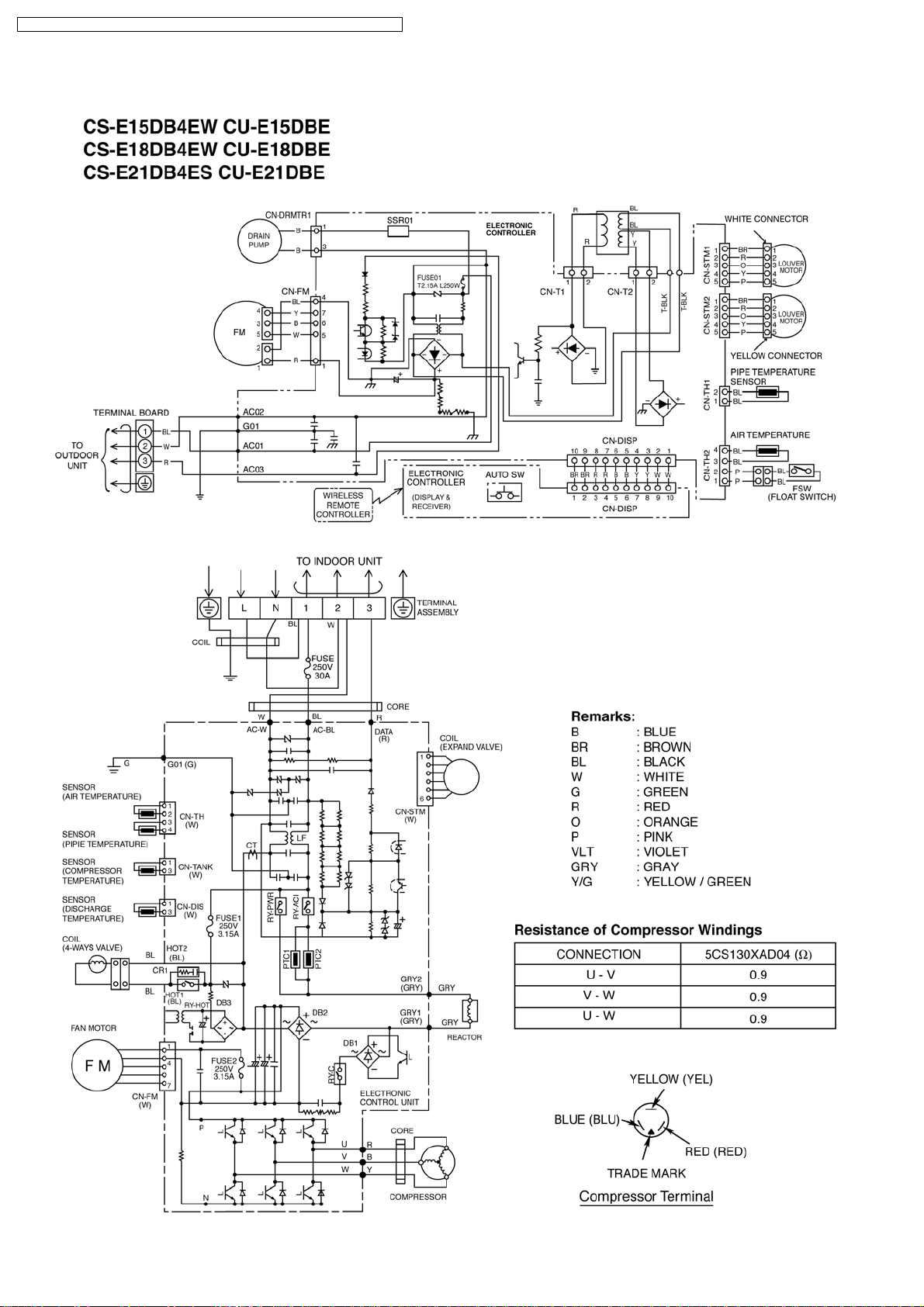
7 Wiring Diagram
16
Page 17
CS-E15DB4EW CU-E15DBE / CS-E18DB4EW CU-E18DBE / CS-E21DB4ES CU-E21DBE
8 Operation Details
8.1. Basic Operation
Inverter control, which equipped with a microcomputer in determining the most suitable operating mode as time passes,
automatically adjust output power for maximum comfort always.
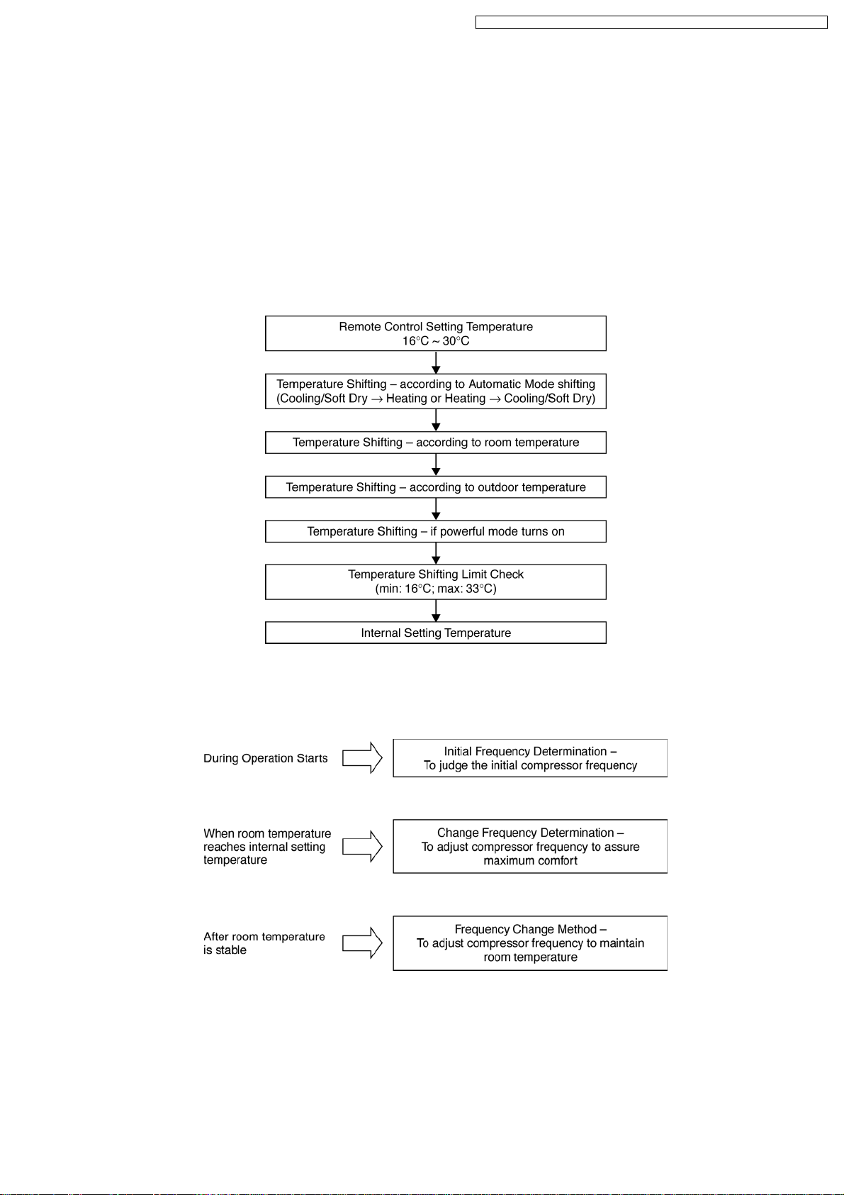
In order to achieve the suitable operation mode, the microcomputer maintains the set temperature by measuring the
temperature of environment and performing temperature shifting.
8.1.1. Temperature Shifting Flow
The compressor at outdoor unit is operating following the frequency instructed by the microcomputer at indoor unit that judging the
condition according to internal setting temperature.
17
Page 18
CS-E15DB4EW CU-E15DBE / CS-E18DB4EW CU-E18DBE / CS-E21DB4ES CU-E21DBE
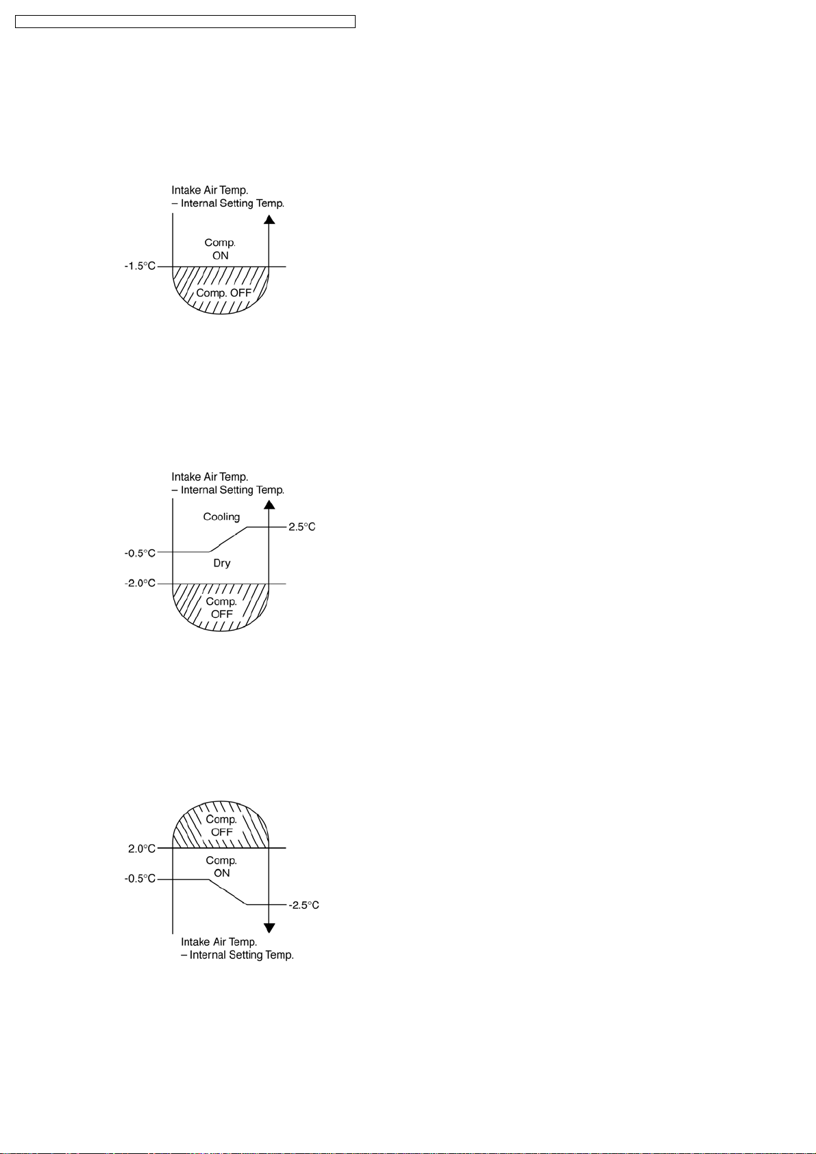
8.1.2. Cooling Operation
8.1.2.1. Thermostat control
• Compressor is OFF when Intake Air Temperature - Internal Setting Tempe rature < -1.5°C.
• Compressor is ON after waiting for 3 minutes, if the Intake Air Temperature - Internal Setting Temperature > Compressor OFF
point.
8.1.3. Soft Dry Operation
8.1.3.1. Thermostat control
• Compressor is OFF when Intake Air Temperature - Internal Setting Tempe rature < -2.0°C.
• Compressor is ON after waiting for 3 minutes, if the Intake Air Temperature - Internal Setting Temperature > Compressor OFF
point.
8.1.4. Heating Operation
8.1.4.1. Thermostat control
• Compressor is OFF when Intake Air Temperature - Internal Setting Temperature > +2.0°C.
• Compressor is ON after waiting for 3 minutes, if the Intake Air Temperature - Internal Setting Temperature < Compressor OFF
point.
18
Page 19
CS-E15DB4EW CU-E15DBE / CS-E18DB4EW CU-E18DBE / CS-E21DB4ES CU-E21DBE
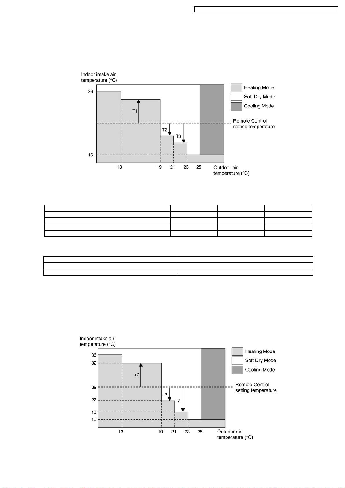
8.1.5. Automatic Operation
This mode can be set using remote control and the operation is decided by remote control setting temperature, indoor intake air
temperature and outdoor air temperature.
During operation mode judgment, indoor fan motor (with speed of Lo-) and outdoor fan motor are running for 30 seconds to detect
the indoor intake and outdoor air temperature. The operation mode is decided based on below chart.
Values of T1, T2, and T3 depend on remote control setting temperature, as shown in below table. After the adjustment of T1, T2
and T3 values, the operation mode for that particular environment and remote control setting is judged and performed, based on
the above operation mode chart, every 30 minutes.
Remote Control Setting Temperature (°C) T1 T2 T3
16 ~ 18 +10 -3 -5
19 ~ 22 +8 -3 -7
23 ~ 26 +7 -3 -7
27 ~ 30 +6 -3 -8
There is a temperature shifting on T1, T2, and T3 if the operation mode judged is changed from Cooling/Soft Dry to Heating or vice
verse.
Operation Mode change from Temperature shifts (°C)
Cooling/Soft Dry→Heating -2
Heating→Cooling/Soft Dry +2
Example of operation mode chart adjustment:
From the above table, if remote control setting temperature = 25,
T1 = 25 + 7 = 32; T2 = 25 - 3 = 22; T3 = 25 - 7 = 18
The operation mode chart for this example is as shown in below figure and the operation mode to be performed will depend on
indoor intake air temperature and outdoor air temperature at the time when the judgment is made.
19
Page 20
CS-E15DB4EW CU-E15DBE / CS-E18DB4EW CU-E18DBE / CS-E21DB4ES CU-E21DBE
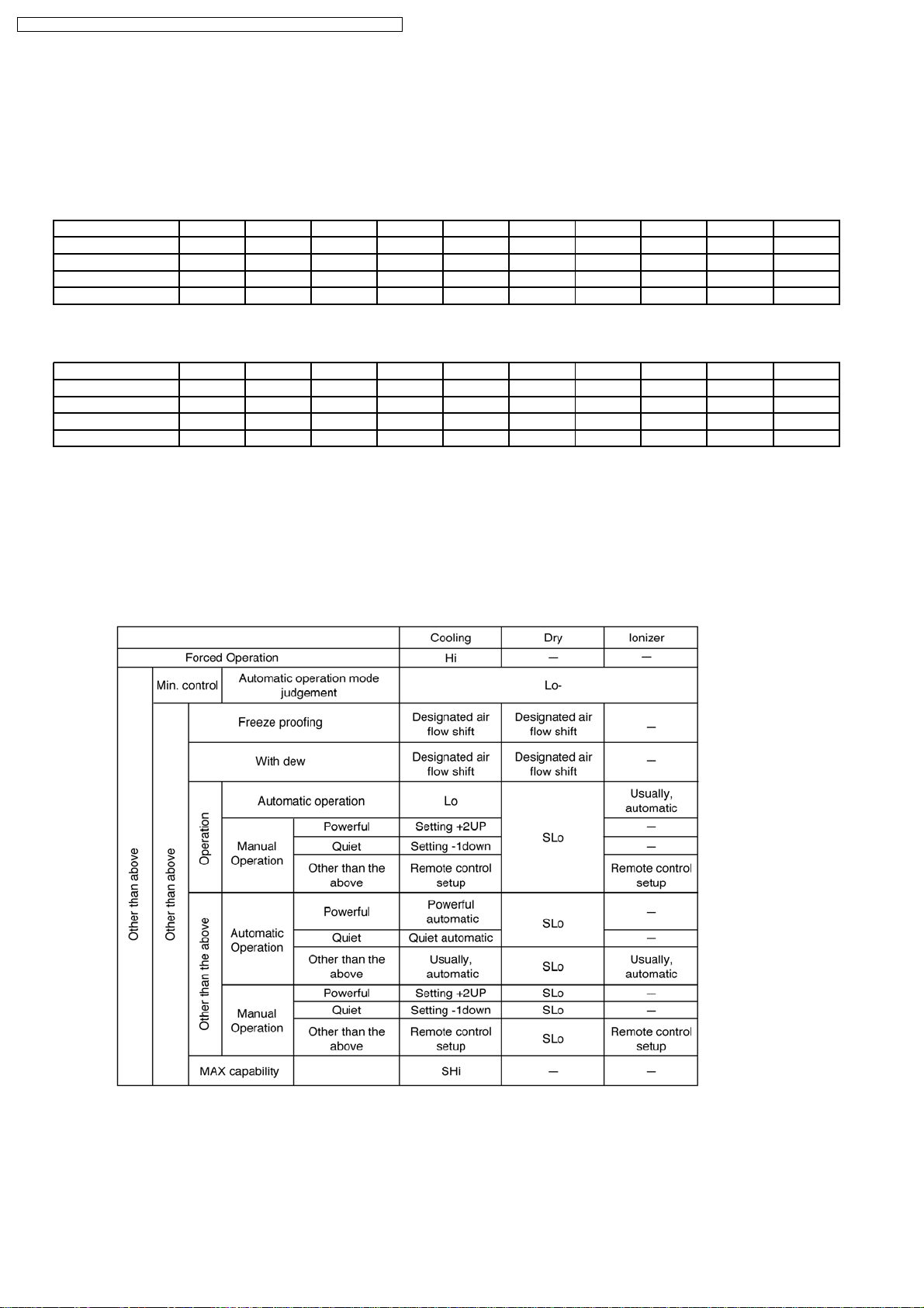
8.1.6. Indoor Fan Motor Operation
A. Basic Rotation Speed (rpm)
• Required rotation speed for fan is set to respond to the remote control setting (10 rpm unit)
[Cooling, Dry, Fan]
Remote Control — — O O O O O — — —
Tab (rpm) PSHI SHI Hi Me+ Me Me- Lo Lo- SLo SSLo
E15D 600 560 560 495 480 425 400 370 310 200
E18D 680 640 590 563 510 488 430 410 350 200
E21D 800 750 700 660 600 560 510 480 410 200
[Heating]
Remote Control — — O O O O O — — —
Tab (rpm) PSHi SSHi SHi Me+ Me Me- Lo Lo- SLo SSLo
E15D 650 610 600 545 540 495 480 440 300 200
E18D 740 690 640 618 560 553 490 490 320 200
E21D 870 820 770 745 670 655 580 570 370 200
B. Indoor Fan Control
i. Indoor fan control operation outline
1. Cooling / Dry
20
Page 21
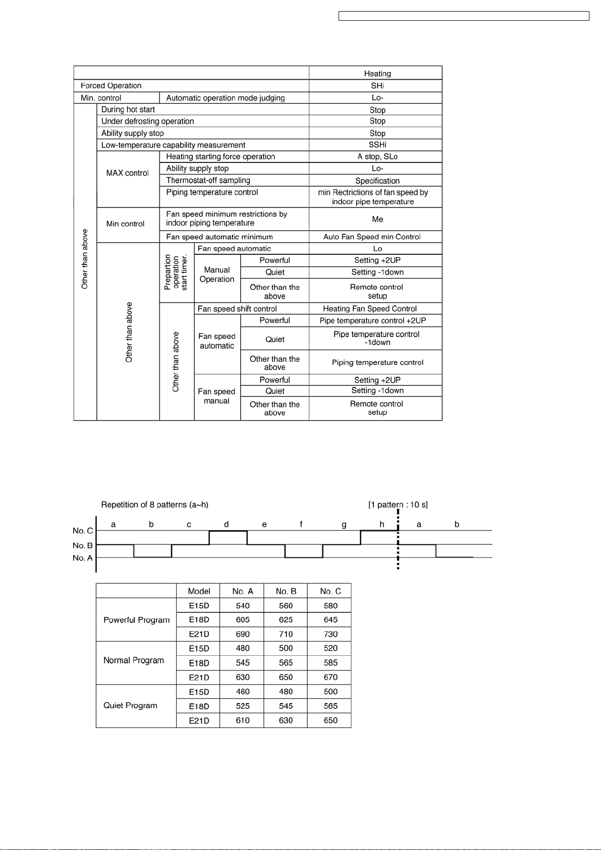
2. Heating
CS-E15DB4EW CU-E15DBE / CS-E18DB4EW CU-E18DBE / CS-E21DB4ES CU-E21DBE
ii. Auto Fan Speed
1. Cooling
21
Page 22

CS-E15DB4EW CU-E15DBE / CS-E18DB4EW CU-E18DBE / CS-E21DB4ES CU-E21DBE
2. Heating
Note:
a. UP:
• If move from Lo, the fan speed will be shifted to Maximum 1520 rpm.
• If move from Maximum, the fan speed no change.
• In up zone, 10 rpm is added for every 10s until Maximum 1520 rpm.
b. DOWN:
• The fan speed will be decreased one step every 10 sec. until Minimum 1270 rpm.
c. Current Output Fixed:
• Maintain at present fan speed.
d. Instantaneous Maximum:
• Fan speed will be increased to maximum auto fan speed.
e. Temperature in ( ) is for Powerful Mode operation.
C. Fan Motor Control
1. Motor specification
High voltage PWM Motor
2. Feedback Control
a. Number-of-rotations feedback
Immediately after the fan started, rpm is checked and duty is added, and feedback control is performed. For high voltage
PWM motor, it is done once every 0.5 second.
b. Offset duty T max/min limit
High voltage PWM motor has maximum offset duty.
(Refer Indoor fan motor control basic rotation speed)
3. Abnormal Detection Control
Conditions:
a. Out of rhythm signal input
b. If feedback number of rotations exceeded #2550 r/min or when less than #50 r/min.
Control: Fans stop
Return: Restart after 5 seconds
* It will not detect the out of rhythm condition within 5s for phase control motor (PWM motor is when duty=0) after start.
A fan stops when condition (1) and (2) happen within 25.0 seconds after fan starting, and if this happens for continuously
7 times, it will not retry.
→ FM lock processing
4. Restart Prohibition Control
Restart is prohibited within 5s for phase control motor (PWM motor is when duty=0) after fan stop (except re-ON the power
supply).
22
Page 23
CS-E15DB4EW CU-E15DBE / CS-E18DB4EW CU-E18DBE / CS-E21DB4ES CU-E21DBE
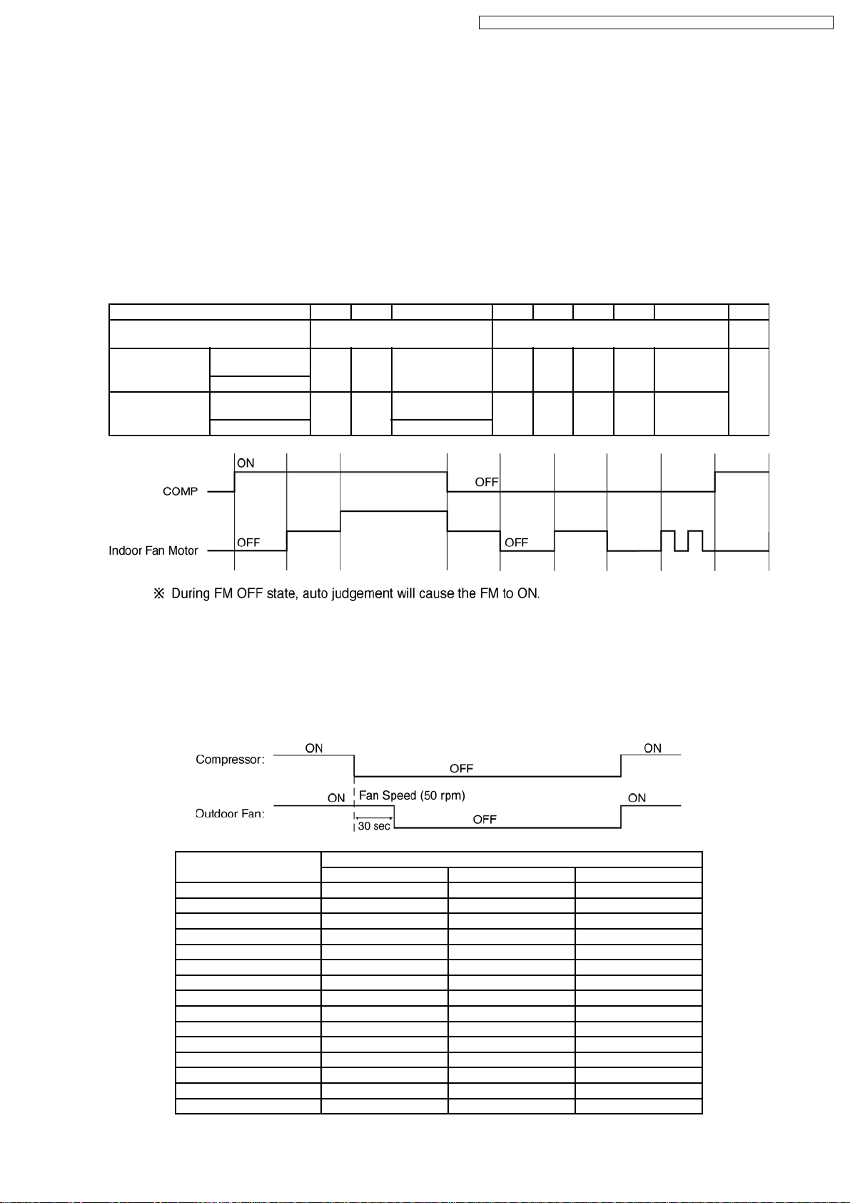
D. Deodorizing Control
i. Control condition
Control at cooling/dry operation and auto fan speed.
No Deodorizing Control is performed during ON timer standby operation and during Anti-freezing control prevention.
ii. Operation
The odor status is arranged as below and it is shifted as follow.
* When COMP is ON 1→2→3
(Shift to 4 when COMP is OFF)
* When COMP is OFF 4→5→6→7→6
(Shift to 1 when COMP is ON)
* Start from 4 if the Thermostat is OFF during the start operation.
Odor Status 1 2 3 4 5 6 7 6.7.6... 1
Status Shift
according to COMP
Status Shift
according
to time (s) Dry zone ON
Fan Speed
Cooling
zone
Cooling
zone
Dry zone SLo
40 50 — 30 90 20 90 20.90.20...
OFF SSLo
ON OFF ON
Auto Fan Speed
SSLo OFF SSLo OFF SSLo.OFF...
←→
7
8.1.7. Outdoor Fan Motor Operation
Outdoor fan motor is operated with 15 fan speed. It starts when compressor starts operation and it stops 30 seconds after
compressor stops operation for speed no.8.
No. RPM during Fan Speed (rpm)
E21D E18D E15D
15 75 73 71
14 75 73 71
13 70 68 66
12 68 66 64
11 64 62 60
10 62 60 60
9 58 58 58
8 50 50 50
7 45 45 45
6 40 40 40
5 35 35 35
4 30 30 30
3 25 25 25
2 20 20 20
1 15 15 15
23
Page 24
CS-E15DB4EW CU-E15DBE / CS-E18DB4EW CU-E18DBE / CS-E21DB4ES CU-E21DBE
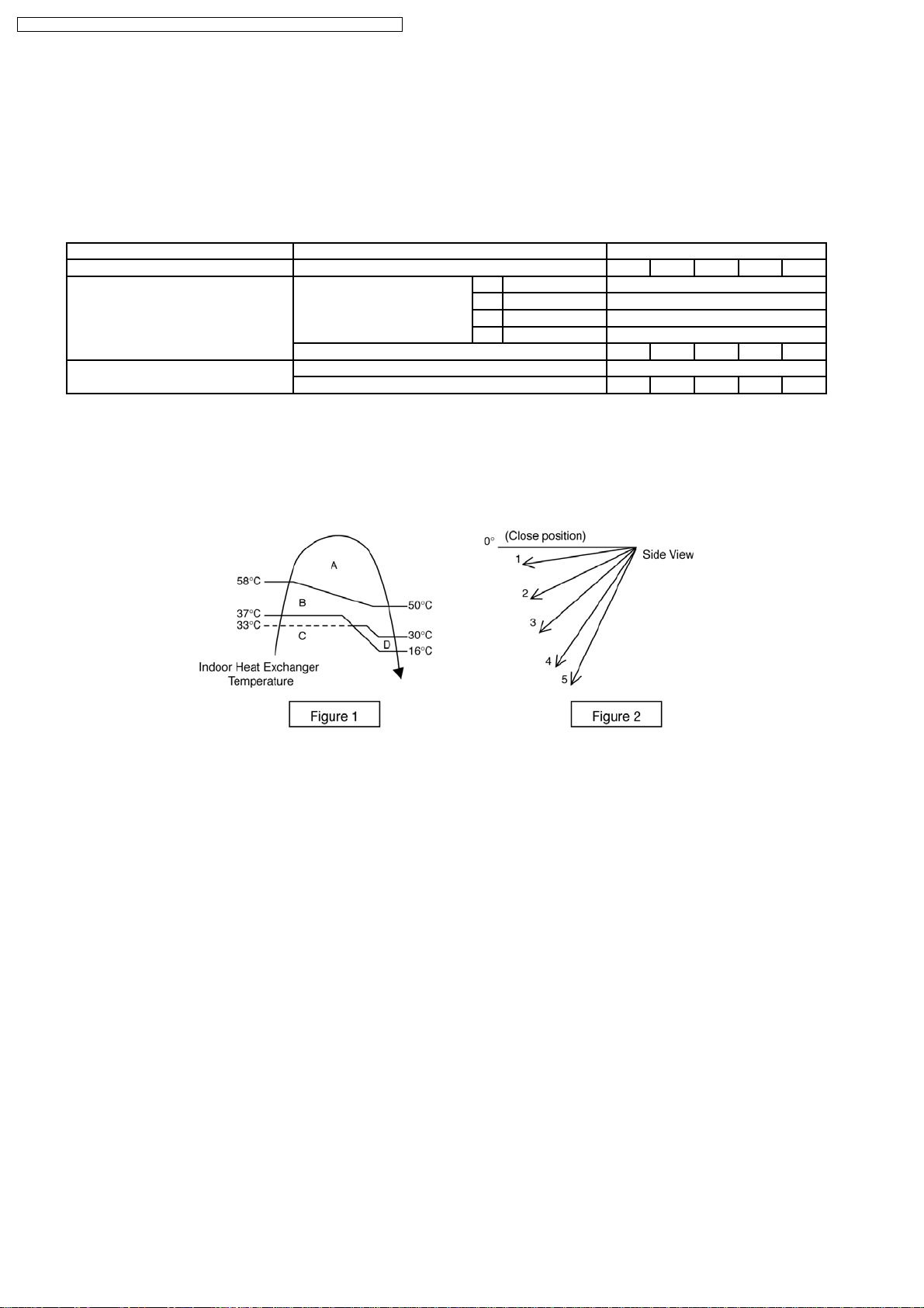
8.1.8. Airflow Direction
1. There are one types of airflow, vertical airflow (directed by horizontal vane).
2. Control of airflow direction can be automatic (angles of direction is determined by operation mode, heat exchanger temperature
and intake air temperature) and manual (angles of direction can be adjusted using remote control).
8.1.8.1. Vertical Airflow
Operation Mode Airflow Direction Vane Angle (°)
1 2 3 4 5
Heating Auto with Heat Exchanger A Downward fix 70
Temperature B Downward fix 70
C Upward fix 20
D Upward fix 20
Manual 20 - - - 70
Cooling, Soft Dry and Ion Auto 20 ~ 70
Manual 20 - - - 70
1. Automatic vertical airflow direction can be set using remote control; the vane swings up and down within the angles as stated
above. For heating mode operation, the angle of the vane depends on the indoor heat exchanger temperature as Figure 1
below. When the air conditioner is stopped using remote control, the vane will shift to close position.
2. Manual vertical airflow direction can be set using remote control; the angles of the vane are as stated above and the positions
of the vane are as Figure 2 below. When the air conditioner is stopped using remote control, the vane will shift to close position.
8.1.9. Quiet operation (Cooling Mode/Cooling area of Dry Mode)
A. Purpose
To provide quiet cooling operation compare to normal operation.
B. Control condition
a. Quiet operation start condition
• When “quiet” button at remote control is pressed.
Quiet LED illuminates.
b. Quiet operation stop condition
1. When one of the following conditions is satisfied, quiet operation stops:
a. Powerful button is pressed.
b. Stop by OFF/ON switch.
c. Timer “off” activates.
d. Quiet button is pressed again.
2. When quiet operation is stopped, operation is shifted to normal operation with previous setting.
3. When fan speed is changed, quiet operation is shifted to quiet operation of the new fan speed.
4. When operation mode is changed, quiet operation is shifted to quiet operation of the new mode.
5. During quiet operation, if timer “on” activates, quiet operation maintains.
6. After off, when on back, quiet operation is not memorised.
24
Page 25

CS-E15DB4EW CU-E15DBE / CS-E18DB4EW CU-E18DBE / CS-E21DB4ES CU-E21DBE
C. Control contents
1. Fan speed is changed from normal setting to quiet setting of respective fan speed.
This is to reduce sound of Hi, Me, Lo for 3dB.
2. Fan speed for quiet operation is -1 step from setting fan speed.
8.1.9.1. Quiet operation (Heating)
A. Purpose
To provide quiet heating operation compare to normal operation.
B. Control condition
a. Quiet operation start condition
• When “quiet” button at remote control is pressed.
Quiet LED illuminates.
b. Quiet operation stop condition
1. When one of the following conditions is satisfied, quiet operation stops:
a. Powerful button is pressed.
b. Stop by OFF/ON switch.
c. Timer “off” activates.
d. Quiet button is pressed again.
2. When quiet operation is stopped, operation is shifted to normal operation with previous setting.
3. When fan speed is changed, quiet operation is shifted to quiet operation of the new fan speed.
4. When operation mode is changed, quiet operation is shifted to quiet operation of the new mode, except fan only mode.
5. During quiet operation, if timer “on” activates, quiet operation maintains.
6. After off, when on back, quiet operation is not memorised.
C. Control contents
a. Fan Speed manual
1. Fan speed is changed from normal setting to quiet setting of respective fan speed.
This is to reduce sound of Hi, Me, Lo for 3dB.
2. Fan speed for quiet operation is -1 step from setting fan speed.
3. Fan Speed Auto
Indoor FM RPM depends on pipe temp sensor of indoor heat exchanger.
25
Page 26
CS-E15DB4EW CU-E15DBE / CS-E18DB4EW CU-E18DBE / CS-E21DB4ES CU-E21DBE
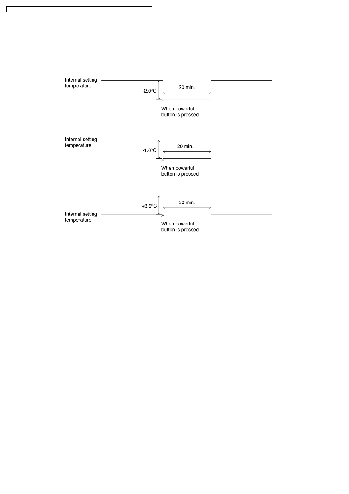
8.1.10. Powerful Mode Operation
When the powerful mode is selected, the internal setting temperature will shift to achieve the setting temperature quickly.
(a) Cooling Operation
(b) Soft Dry Operation
(c) Heating Operation
8.1.11. 24-Hour Real Time Timer Control
ON Timer
ON timer can be set using remote control, the unit with timer set will start operate earlier than the setting time. This is to provide
a comfortable environment when reaching the set ON time.
Outdoor fan-ON instructions are transmitted to outdoor unit 60 minutes before setting time, then sampling the outdoor / indoor
temperature with indoor fan at Lo- for 30 seconds. After detecting the indoor/outdoor temperature, the unit determines the
operation starting time according to the load. However, when outdoor unit is operating, the preparation starting time will be set
to minimum.
OFF Timer
When the OFF timer is set by using the remote control, the unit stop operate according to the desired setting.
Notes:
1. By pressing ON/OFF operation button, the ON Timer/OFF Timer setting will not be cancelled.
2. To cancel the previous timer setting, press CANCEL button.
3. To activate the previous timer setting, press SET button.
4. If main power supply is switched off, the Timer setting will be cancelled.
26
Page 27
CS-E15DB4EW CU-E15DBE / CS-E18DB4EW CU-E18DBE / CS-E21DB4ES CU-E21DBE
8.1.12. Auto Restart Control
1. When the power supply is cut off during the operation of air conditioner, the compressor will re-operate within three to four
minutes (there are 10 patterns between 2 minutes 58 seconds and 3 minutes 52 seconds to be selected randomly) after power
supply resumes.
2. This type of control is not applicable during ON/OFF Timer setting.
8.1.13. Indication Panel
LED POWER TIMER QUIET POWERFUL AIR SWING
Color Green Orange Orange Orange Orange
Light ON Operation ON Timer Setting ON Quiet Mode ON Powerful Mode ON Auto Air Swing ON
Light OFF Operation OFF Timer Setting OFF Quiet Mode OFF Powerful Mode OFF Auto Air Swing OFF
Note:
• If POWE R LED is blinking, the possible operations of the unit are Hot Start, during Deice operation, operation mode
judgment, or delay ON timer sampling.
• If Timer LED is blinking, there is an abnormality operation occurs.
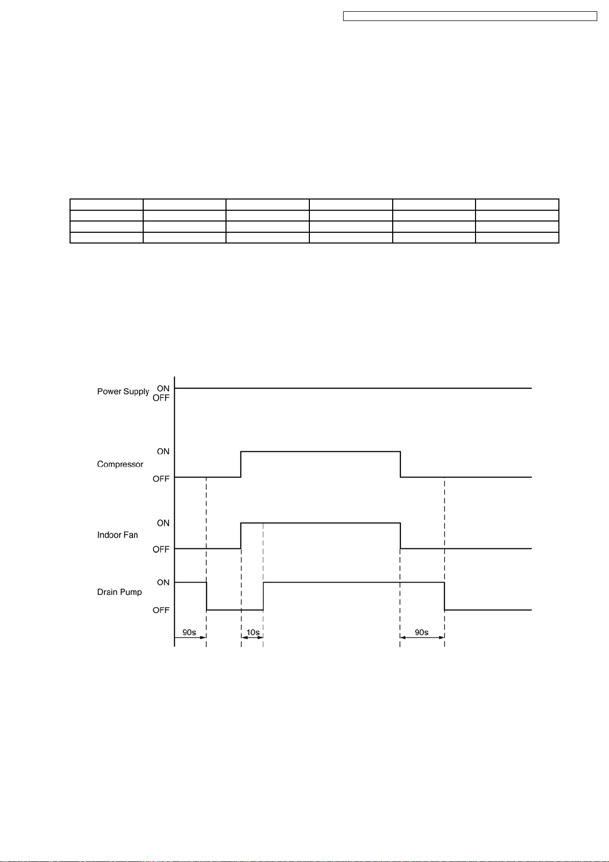
8.1.14. Drain Pump Control Operation
• To drain out the condensed watar trapped in the drain pan in order to prevent the condensed water from overflowing from the
drain pan and leaking.
• Drain Pump starts to operate 10 sec. after compressor and Indoor fan ON.
• Drain Pump stop to operate 90 sec. after compressor OFF.
Drain Pump Error
Drain Pump Error occurs when:
- Within 20 minutes, the float switch is ON twice.
- Float switch is ON continuously for 2 minutes 30 seconds.
When error occurs, the timer indicator blinks and the unit stops its operation.
27
Page 28
CS-E15DB4EW CU-E15DBE / CS-E18DB4EW CU-E18DBE / CS-E21DB4ES CU-E21DBE
8.2. Protection Control Features
8.2.1. Protection Control For All Operations
8.2.1.1. Time Delay Safety Control
1. The compressor will not start for three minutes after stop of operation.
2. This control is not applicable if the power supply is cut off for 20 seconds and on again or after 4-way valve deices condition.
8.2.1.2. 30 Seconds Forced Operation
1. Once the compressor starts operation, it will not stop its operation for 30 seconds.
2. However, it can be stopped using remote control or Auto Switch at indoor unit.
8.2.1.3. Total Running Current Control
1. When the outdoor unit total running current (AC) exceeds X value, the frequency instructed for compressor operation will be
decreased.
2. If the running current does not exceed X value for five seconds, the frequency instructed will be increased.
3. However, if total outdoor unit running current exceeds Y value, compressor will be stopped immediately for 2 minutes.
Model E15D E18D E21D
Operation Mode X(A) Y(A) X(A) Y(A) X(A) Y (A)
Cooling/Soft Dry (A) 7.20 17 8.74 17 11.02 17
Cooling/Soft Dry (B) & (C) 6.30 17 7.70 17 9.59 17
Heating 8.60 17 10.71 17 11.53 17
4. The first 30 minutes of cooling operation, (A) will be applied.
8.2.1.4. IPM (Power transistor) Prevention Control
A. Overheating Prevention Control
1. When the IPM temperature rises to 100°C, compressor operation will stop immediately.
2. Compressor operation restarts after three minutes the temperature decreases to 95°C.
B. DC Peak Current Control
1. When electric current to IPM exceeds set value of 22.33 A, the compressor will stop operate. Then, operation will restart
after three minutes.
2. If the set value is exceeded again more than 30seconds after the compressor starts, the operation will restart after 1 minute.
3. If the set value is exceeded again within 30 seconds after the compressor starts, the operation will restart after one minute.
If this condition repeats continuously for seven times, all indoor and outdoor relays will be cut off.
28
Page 29
CS-E15DB4EW CU-E15DBE / CS-E18DB4EW CU-E18DBE / CS-E21DB4ES CU-E21DBE
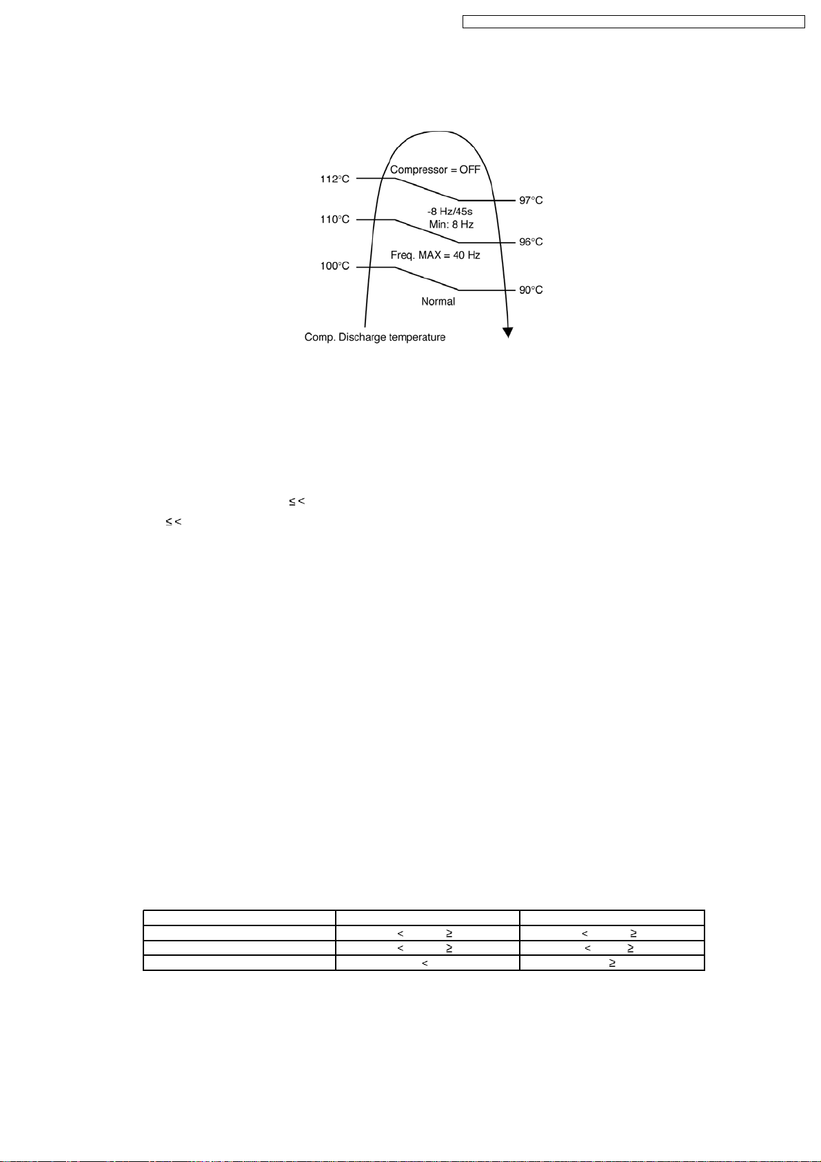
8.2.1.5. Compressor Overheating Prevention Control
Instructed frequency for compressor operation will be regulated by compressor discharge temperature. The changes of frequency
are as below figure.
8.2.1.6. Low Pressure Prevention Control (Gas Leakage Detection)
a. Control start conditions
Control will perform when (1) - (3) condition continues operation for 5 minute and (4) is fulfill.
1. During cooling and dry operation: Frequency more than normal Fcmax 78 Hz (E15D), 86 Hz (E18D), 102 Hz (E21D).
During heating operation: Frequency more than normal Fh 71 Hz (E15D), 86 Hz (E18D), 92 Hz (E21D).
2. Outdoor total current I cooling: Ib
Heating: Ib
Ic = Ia = 1.65 A
Ib = 0.65 A
3. It is not during deice operation.
4. During cooling and dry operation: indoor suction-indoor piping temperature is below 4°C.
During of heating operation: Indoor piping temperature-indoor suction is under 5°C.
Control contents:
• compressor stops (restart after 3 minutes)
• if happen 2 times within (20 minutes), perform the following operation
1) Unit stop operation
2) Timer LED blink and “F91” indicated
I Ic
I Ia
8.2.1.7. Low Frequency Protection Control 1
When the compressor operate at frequency lower than 25 Hz continued for 20 minutes, the operation frequency will be increased
to 24 Hz for two minutes.
8.2.1.8. Low Frequency Protection Control 2
When all the below conditions occur, minimum value (Freq. MIN) for the frequency instructed to compressor will change to 30 Hz
for cooling mode operation and 20 Hz for heating mode operation.
Temperature, T, for: Cooling/Soft Dry Heating
Indoor intake air (°C) T 14 or T 30 T 14 or T 28
Outdoor air (°C) T 13 or T 38 T 4orT 24
Indoor heat exchanger (°C) T 30 T 0
29
Page 30
CS-E15DB4EW CU-E15DBE / CS-E18DB4EW CU-E18DBE / CS-E21DB4ES CU-E21DBE
8.2.2. Protection Control For Cooling & Soft Dry Operation
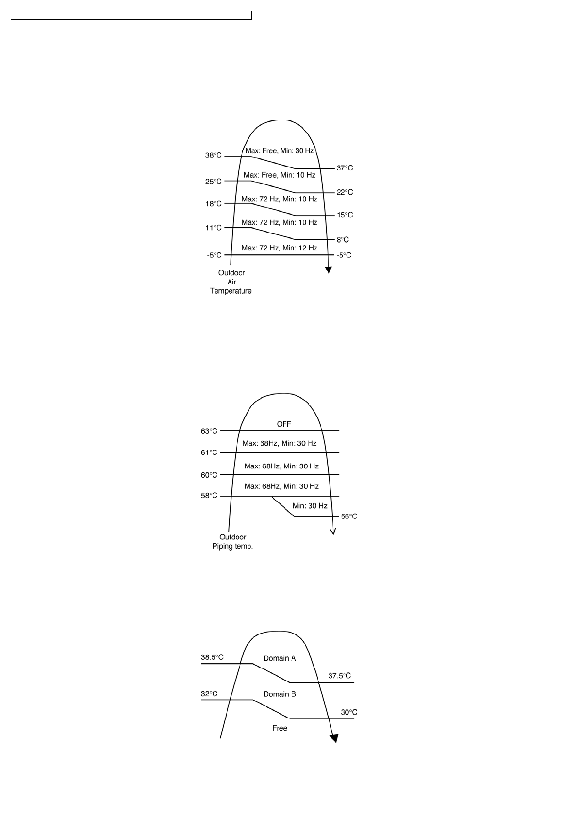
8.2.2.1. Outdoor Air Temperature Control
The compressor operating frequency is regulated in accordance to the outdoor air temperature as shown in the diagram below.
This control will begin one minute after the compressor starts.
8.2.2.2. Cooling Overload Control
i. Pipe temperature limitation/restriction
• Detects the Outdoor pipe temperature and carry out below restriction/limitation (Limit the compressor Operation frequency)
• The compressor stop if outdoor pipe temperature exceeds 63°C
• If the compressor stops 4 times in 20 minutes, Timer LED blinking (F95: outdoor high pressure rise protection)
ii. Electrical part temperature rise protection control
1. Purpose
To prevent electronic components temperature rise during cooling overload.
2. Judgement Conditions
a) Outdoor temperature
b) Outdoor total current above 5 A.
30
Page 31

CS-E15DB4EW CU-E15DBE / CS-E18DB4EW CU-E18DBE / CS-E21DB4ES CU-E21DBE
3. Control contents
In the outdoor fan speed no.
i) In protectorate Domain A is referred to as min 660 rpm.
ii) In protectorate Domain B, it is referred to as min 600 rpm.
4. Condition resolutive
It is canceled when it stops satisfying all of the above-mentioned.
8.2.2.3. Anti-Freezing Control
1. When indoor heat exchanger temperature is lower than 7°C continuously for six minutes, compressor will stop operating.
2. Compressor will resume its operation three minutes after the indoor heat exchanger is higher than 13°C.
3. At the same time, indoor fan speed increase +20 rpm compared to its normal operation.
4. If indoor heat exchanger temperature is higher than 13°C for five minutes, the fan speed will return to its normal operation.
8.2.2.4. Anti-Dew Formation Control
a. Purpose
To prevent dew.
b. Control start conditions
When indoor are ceiling floor, duct and mini casette.
c. Control contents
Hz control is carried out according to the spray prevention status transmitted from indoor.
Spray prevention
status(transmitted indoor)
0 (it usually controls Usually, control Usually, control
1 (rise) Relative change control priority On tap up/10 seconds
2 (changeless) Changeless Changeless
3 (down) -2 Hz/10 seconds -2 Hz/10 seconds
Relative control domain MAX domain
* Once the standup went into the down domain by Fcmax as for the Fcmax domain, it shifts to relative change control domain.
When the higher rank of relative control has this control and the status signal of 2-3 has come out.
Relative change control is stopped and follows directions of spray control.
Priority is given to the which is larger when freeze prevention down status and spray prevention down status are transmitted
simultaneously.
In the case of spray status
0, it is referred to as maxFc.
Control contents
Change is once to 10 seconds.
31
Page 32

CS-E15DB4EW CU-E15DBE / CS-E18DB4EW CU-E18DBE / CS-E21DB4ES CU-E21DBE
8.2.3. Protection Control For Heating Operation
8.2.3.1. Intake Air Temperature Control
Compressor will operate at Max freq 94 (E15D), 128 (E18D, E21D) Hz if either one of the below conditions occur:
1. When the indoor intake air temperature is less than 21°C and remote control setting fan speed is lower Me-.
2. When the indoor intake air temperature is 35°C or above.
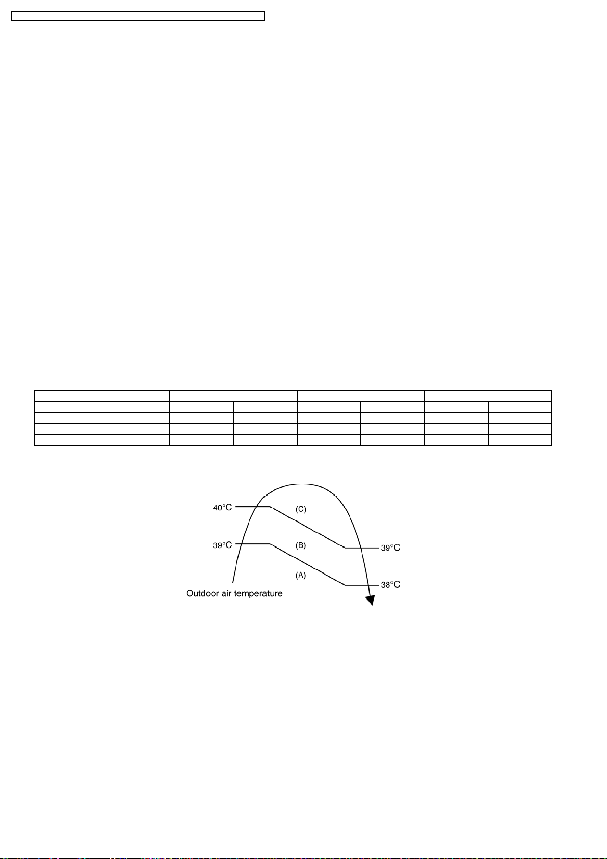
8.2.3.2. Outdoor Air Temperature Control
The Max current value is regulated in accordance to the outdoor air temperature as shown in the below figures.
8.2.3.3. Overload Protection Control
The compressor operating frequency is regulated in accordance to indoor heat exchanger temperature as shown in below figures.
32
Page 33

CS-E15DB4EW CU-E15DBE / CS-E18DB4EW CU-E18DBE / CS-E21DB4ES CU-E21DBE
8.2.3.4. Deice Control
• Deice starts to prevent frosting at outdoor heat exchanger.
• Deice operation detection commences after minimum 60 minutes of Heating Operation.
• The outdoor heat exchanger temperature drops below 3°C for long period (minimum 40 minutes) during compressor is in
operation, the deice operation may starts.
33
Page 34

CS-E15DB4EW CU-E15DBE / CS-E18DB4EW CU-E18DBE / CS-E21DB4ES CU-E21DBE
9 Operating Instructions
34
Page 35

CS-E15DB4EW CU-E15DBE / CS-E18DB4EW CU-E18DBE / CS-E21DB4ES CU-E21DBE
35
Page 36

CS-E15DB4EW CU-E15DBE / CS-E18DB4EW CU-E18DBE / CS-E21DB4ES CU-E21DBE
36
Page 37

CS-E15DB4EW CU-E15DBE / CS-E18DB4EW CU-E18DBE / CS-E21DB4ES CU-E21DBE
37
Page 38

CS-E15DB4EW CU-E15DBE / CS-E18DB4EW CU-E18DBE / CS-E21DB4ES CU-E21DBE
38
Page 39

CS-E15DB4EW CU-E15DBE / CS-E18DB4EW CU-E18DBE / CS-E21DB4ES CU-E21DBE
39
Page 40

CS-E15DB4EW CU-E15DBE / CS-E18DB4EW CU-E18DBE / CS-E21DB4ES CU-E21DBE
40
Page 41

CS-E15DB4EW CU-E15DBE / CS-E18DB4EW CU-E18DBE / CS-E21DB4ES CU-E21DBE
41
Page 42

CS-E15DB4EW CU-E15DBE / CS-E18DB4EW CU-E18DBE / CS-E21DB4ES CU-E21DBE
10 Installation And Servicing Air Conditioner Using R410A
10.1. Outline
10.1.1. About R410A Refrigerant
1. Converting air conditioners to R410A
Since it was declared in1974 that chlorofluorocarbons (CFC), hydro chlorofluorocarbons (HCFC) and other substances pose a
destructive danger to the ozone layer in the earth´s upper stratosphere (20 to 40 km above the earth), measures have been
taken around the world to prevent this destruction.
The R22 refrigerant which has conventionally been used in ACs is an HCFC refrigerant and, therefore, possesses this ozonedestroying potential. International regulations (the Montreal Protocol on Ozone-Damaging Substances) and the domestic laws
of various countries call for the early substitution of R22 by a refrigerant which will not harm the ozone layer.
• In ACs, the HFC refrigerant which has become the mainstream alternative is called R410A.Compared with R22, the
pressure of R410A is approximately 1.6 times as high at the same refrigerant temperature, but the energy efficiency is about
the same. Consisting of hydrogen (H), fluorine (F) and carbon (C), R410A is an HFC refrigerant. Another typical HFC
refrigerant is R407C. While the energy efficiency of R407C is somewhat inferior to that of R410A, it offers the advantage
of having pressure characteristics which are about the same as those of R22, and is used mainly in packaged ACs.
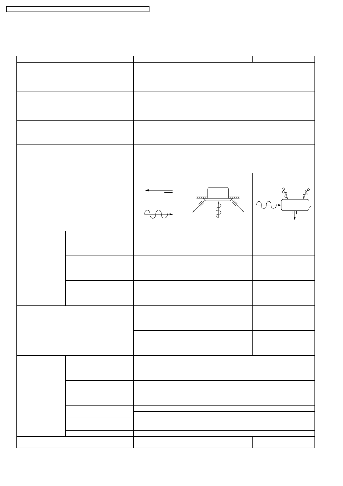
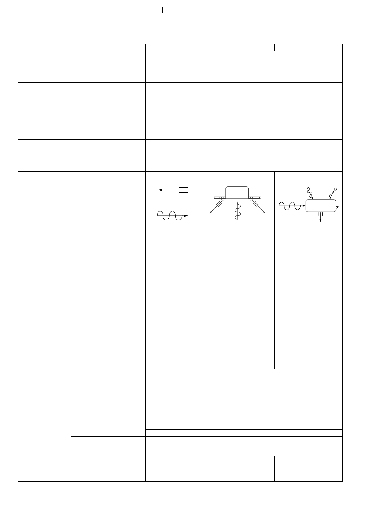
2. The characteristics of HFC (R410A) refrigerants
a. Chemical characteristics
The chemical characteristics of R410A are similar to those of R22 in that both are chemically stable, non-flammable
refrigerants with low toxicity.
However, just like R22, the specific gravity of R410A gas is heavier than that of air. Because of this, it can cause an oxygen
deficiency if it leaks into a closed room since it collects in the lower area of the room. It also generates toxic gas when it is
directly exposed to a flame, so it must be used in a well ventilated environment where it will not collect.
Table 1 Physical comparison of R410A and R22
Composition (wt%) R32/R125 (50/50) R22 (100)
Boiling point (°C) -51.4 -40.8
Vaporizing pressure (25°C) 1.56 Mpa (15.9 kgf/cm2) 0.94 Mpa (9.6 kgf/cm2)
Saturated vapor density 64.0 kg/m
Flammability Non-flammable Non-flammable
Ozone-destroying point (ODP) 0 0.055
Global-warming point (GWP) 1730 1700
R410A R22
3
44.4 kg/m
3
b. Compositional change (pseudo-azeotropic characteristics)
R410A is a pseudo-azeotropic mixture comprising the two components R32 and R125. Multi-component refrigerants with
these chemical characteristics exhibit little compositional change even from phase changes due to vaporization (or
condensation), which means that there is little change in the circulating refrigerant composition even when the refrigerant
leaks from the gaseous section of the piping.
Accordingly, R410A can be handled in almost the same manner as the single-component refrigerant R22. However, when
charging, because there is a slight change in composition between the gas phase and the liquid phase inside a cylinder or
other container, charging should basically begin with the liquid side.
c. Pressure characteristics
As seen in Table 2, the gas pressure of R410A is approximately 1.6 times as high as that of R22 at the same refrigerant
temperature, which means that special R410A tools and materials with high-pressure specifications must be used for all
refrigerant piping work and servicing.
Table 2 Comparison of R410A and R22 saturated vapor density
Refrigerant Temperature (°C) R410A R22
-20 0.30 0.14
0 0.70 0.40
20 1.35 0.81
40 2.32 1.43
60 3.73 2.33
65 4.15 2.60
Unit: MPa
42
Page 43

CS-E15DB4EW CU-E15DBE / CS-E18DB4EW CU-E18DBE / CS-E21DB4ES CU-E21DBE
d. R410A refrigerating machine oil
Conventionally, mineral oil or a synthetic oil such as alkylbenzene has been used for R22 refrigerating machine oil. Because
of the poor compatibility between R410A and conventional oils like mineral oil, however, there is a tendency for the
refrigerating machine oil to collect in the refrigerating cycle. For this reason, polyester and other synthetic oils which have
a high compatibility with R410A are used as refrigerating machine oil.
Because of the high hygroscopic property of synthetic oil, more care must be taken in its handling than was necessary with
conventional refrigerating machine oils. Also, these synthetic oils will degrade if mixed with mineral oil or alkylbenzene,
causing clogging in capillary tubes or compressor malfunction. Do not mix them under any circumstances.
10.1.2. Safety Measures When Installing/Servicing Refrigerant Piping
Cause the gas pressure of R410A is approximately 1.6 times as high as that of R22, a mistake in installation or servicing could
result in a major accident. It is essential that you use R410A tools and materials, and that you observe the following precautions
to ensure safety.
1. Do not use any refrigerant other than R410A in ACs that have been used with R410A.
2. If any refrigerant gas leaks while you are working, ventilate the room. Toxic gas may be generated if refrigerant gas is exposed
to a direct flame.
3. When installing or transferring an AC, do not allow any air or substance other than R410A to mix into the refrigeration cycle. If
it does, the pressure in the refrigeration cycle can become abnormally high, possibly causing an explosion and/or injury.
4. After finishing the installation, check to make sure there is no refrigerant gas leaking.
5. When installing or transferring an AC, follow the instructions in the installation instructions carefully. Incorrect installation can
result in an abnormal refrigeration cycle or water leakage, electric shock, fire, etc.
6. Do not perform any alterations on the AC unit under any circumstances. Have all repair work done by a specialist. Incorrect
repairs can result in an water leakage, electric shock, fire, etc.
10.2. Tools For Installing/Servicing Refrigerant Piping
10.2.1. Necessary Tools
In order to prevent an R410A AC from mistakenly being charged with any other refrigerant, the diameter of the 3-way valve service
port on the outdoor unit has been changed. Also, to increase its ability to withstand pressure, the opposing dimensions have been
changed for the refrigerant pipe flaring size and flare nut. Accordingly, when installing or servicing refrigerant piping, you must have
both the R410A and ordinary tools listed below.
Type of work Ordinary tools R410A tools
Flaring Flaring tool (clutch type), pipe cutter,
Bending, connecting pipes Torque wrench (nominal diameter 1/4,
Air purging Vacuum pump. Hexagonal wrench
Gas leak inspection Gas leak inspection fluid or soapy water Electric gas leak detector for HFC
*1) You can use the conventional (R22) flaring tool. If you need to buy a new tool, buy the R410A type.
*2) Use when it is necessary to detect small gas leaks.
For other installation work, you should have the usual tools, such as screwdrivers (+,-), a metal-cutting saw, an electrical drill, a hole
core drill (65 or 70 dia.), a tape measure, a level, a thermometer, a clamp meter, an insulation tester, a voltmeter, etc.
Type of work Ordinary tools R410A tools
Refrigerant charging Electronic scale for refrigerant charging.
Brazing (Replacing refrigerating cycle
part*1)
Table 3 Tools for installation, transferring or replacement
reamer
3/8,1/2). Fixed spanner (opposing sides
12 mm, 17 mm, 19 mm). Adjustable
wrench, Spring bender
(opposing sides 4 mm)
Table 4 Tools for serving
Nitrogen blow set (be sure to use nitrogen
blowing for all brazing), and brazing
machine
Copper pipe gauge for clearance
Adjustment, flaring tool (clutch type)*1)
Manifold gauge, charging hose, vacuum
pump adaptor
refrigerant*2)
Refrigerant cylinder. Charging orifice and
packing for refrigerant cylinder
*1) Always replace the dryer of the outdoor unit at the same time. The replacement dryer is wrapped in a vacuum pack. Replace
it last among the refrigerating cycle parts. Start brazing as soon as you have opened the vacuum pack, and begin the vacuuming
operation within 2 hours.
43
Page 44

CS-E15DB4EW CU-E15DBE / CS-E18DB4EW CU-E18DBE / CS-E21DB4ES CU-E21DBE
10.2.2. R410A Tools
1. Copper tube gauge for clearance adjustment
(used when flaring with the conventional flaring tool (clutch
type))
• This gauge makes it easy to set the clearance for the
copper tube to 1.0-1.5 mm from the clamp bar of the
flaring tool.
2. Flaring tool (clutch type)
• In the R410A flaring tool, the receiving hole for the
clamp bar is enlarged so the clearance from the clamp
bar can be set to 0-0.5 mm, and the spring inside the
tool is strengthened to increase the strength of the pipeexpanding torque. This flaring tools can also be used
with R22 piping, so we recommend that you select it if
you are buying a new flaring tool.
Fig. 1 Copper tube gauge for clearance adjustment
Fig. 2 Flaring tool (clutch type)
3. Torque wrenches
Fig. 3 Torque wrenches
Table 5
Conventional wrenches R410A wrenches
For 1/4 (opposite side x torque) 17 mm x 18 N.m (180 kgf.cm) 17 mm x 18 N.m (180 kgf.cm)
For 3/8 (opposite side x torque) 22 mm x 42 N.m (420 kgf.cm) 22 mm x 42 N.m (420 kgf.cm)
For 1/2 (opposite side x torque) 24 mm x 55 N.m (550 kgf.cm) 26 mm x 55 N.m (550 kgf.cm)
4. Manifold gauge
• Because the pressure is higher for the R410A type, the conventional type cannot be used.
Table 6 Difference between R410A and conventional high / low-pressure gauges
High-pressure gauge (red) -76 cmHg - 35 kgf/cm
Low-pressure gauge (blue) -76 cmHg - 17 kgf/cm
Conventional gauges R410A gauges
3
3
-0.1 - 5.3 Mpa -76 cmHg - 53 kgf/cm
-0.1 - 3.8 Mpa -76 cmHg - 38 kgf/cm
3
3
• The shape of the manifold ports has been changed to prevent the possibility of mistakenly charging with another type of
refrigerant.
Table 7 Difference between R410A and conventional manifold port size
Port size 7/16 UNF 20 threads 1/2 UNF 20 threads
Conventional gauges R410A gauges
44
Page 45

CS-E15DB4EW CU-E15DBE / CS-E18DB4EW CU-E18DBE / CS-E21DB4ES CU-E21DBE
5. Charging hose
• The pressure resistance of the charging hose has been
raised to match the higher pressure of R410A. The hose
material has also been changed to suit HFC use, and
the size of the fitting has been changed to match the
manifold ports.
Fig. 4 Manifold gauge charging hose
Table 8 Difference between R410A and conventional charging hoses
Pressure
resistance
Material NBR rubber HNBR rubber Nylon coating inside
Working pressure 3.4 MPa (35 kgf/cm3) 5.1 MPa (52 kgf/cm3)
Bursting pressure 17.2 MPa (175 kgf/cm3) 27.4 MPa (280 kgf/cm3)
Conventional hoses R410A hoses
6. Vacuum pump adaptor
• When using a vacuum pump for R410A, it is necessary
to install an electromagnetic valve to prevent the
vacuum pump oil from flowing back into the charging
hose. The vacuum pump adaptor is installed for that
purpose. if the vacuum pump oil (mineral oil) becomes
mixed with R410A, it will damage the unit.
7. Electric gas leak detector for HFC refrigerant
• The leak detector and halide torch that were used with
CFC and HCFC cannot be used with R410A (because
there is no chlorine in the refrigerant).
• The present R134a leak detector can be used, but the
detection sensitivity will be lower (setting the sensitivity
for R134a at 1, the level for R410A will drop to 0.6).
• For detecting small amounts of gas leakage, use the
electric gas leak detector for HFC refrigerant. (Detection
sensitivity with R410A is about 23 g/year).
Fig. 5 Vacuum pump adaptor
Fig. 6 Electric gas leak detector for HFC refrigerant
45
Page 46

CS-E15DB4EW CU-E15DBE / CS-E18DB4EW CU-E18DBE / CS-E21DB4ES CU-E21DBE
8. Electronic scale for refrigerant charging
• Because of the high pressure and fast vaporizing speed
of R410A, the refrigerant cannot be held in a liquid
phase inside the charging cylinder when charging is
done using the charging cylinder method, causing
bubbles to form in the measurement scale glass and
making it difficult to see the reading. (Naturally, the
conventional R22 charging cylinder cannot be used
because of the differences in the pressure resistance,
scale gradation, connecting port size, etc.)
• The electronic scale has been strengthened by using a
structure in which the weight detector for the refrigerant
cylinder is held by four supports. It is also equipped with
two connection ports, one for R22 (7/16 UNF, 20
threads) and one for R410A (1/2 UNF, 20 threads), so
it can also be used for conventional refrigerant charging.
• There are two types of electronic scales, one for 10-kg
cylinders and one for 20-kg cylinders. (The 10-kg
cylinder is recommended.)
Refrigerant charging is done manually by opening and
closing the valve.
Fig. 7 Electronic scale for refrigerant charging
9. Refrigerant cylinders
• The R410A cylinders are labeled with the refrigerant
name, and the coating color of the cylinder protector is
pink, which is the color stipulated by ARI of the U.S.
• Cylinders equipped with a siphon tube are available to
allow the cylinder to stand upright for liquid refrigerant
charging.
10. Charging orifice and packing for refrigerant cylinders
• The charging orifice must match the size of the charging
hose fitting (1/2 UNF, 20 threads).
• The packing must also be made of an HFC-resistant
material.
Fig. 8 Refrigerant cylinders
Fig. 9 Charging orifice and packing
10.2.3. R410A Tools Which Are Usable for R22 Models
Table 9 R410A tools which are usable for R22 models
R410A tools Usable for R22 models
(1) Copper tube gauge for clearance adjustment OK
(2) Flaring tool (clutch type) OK
(3) Manifold gauge NG
(4) Charging hose NG
(5) Vacuum pump adaptor OK
(6) Electric gas leak detector for HFC refrigerant NG
(7) Electronic scale for refrigerant charging OK
(8) Refrigerant cylinder NG
(9) Charging orifice and packing for refrigerant cylinder NG
46
Page 47

CS-E15DB4EW CU-E15DBE / CS-E18DB4EW CU-E18DBE / CS-E21DB4ES CU-E21DBE
10.3. Refrigerant Piping Work
10.3.1. Piping Materials
It is recommended that you use copper and copper alloy jointless pipes with a maximum oil adherence of 40 mg/10m. Do not use
pipes that are crushed, deformed, or discolored (especially the inside surface). If these inferior pipes are used, impurities may clog
the expansion valves or capillaries.
Because the pressure of ACs using R410A is higher than those using R22, it is essential that you select materials that are
appropriate for these standards.
The thickness of the copper tubing used for R410A is shown in Table 10. Please be aware that tubing with a thickness of only 0.7
mm is also available on the market, but this should never be used.
Soft pipe Thickness (mm)
Nominal diameter Outside diameter (mm) R410A (Reference) R22
1/4 6.35 0.80 0.80
3/8 9.52 0.80 0.80
1/2 12.7 0.80 0.80
10.3.2. Processing and Connecting Piping Materials
When working with refrigerant piping, the following points must
be carefully observed: no moisture od dust must be allowed to
enter the piping, and there must be no refrigerant leaks.
1. Procedure and precautions for flaring work
a. Cut the pipe
Use a pipe cutter, and cut slowly so the pipe will not be
deformed.
b. Remove burrs and clean shavings from the cut surface
If the shape of the pipe end is poor after removing burrs,
or if shavings adhere to the flared area, it may lead to
refrigerant leaks.
To prevent this, turn the cut surface downward and
remove burrs, then clean the surface, carefully.
c. Insert the flare nut (be sure to use the same nut that is
used on the AC unit)
d. Flaring
Check the clamp bar and the cleanliness of the copper
pipe.
Be sure to use the clamp bar to do the flaring with
accuracy. Use either an R410A flaring tool, or a
conventional flaring tool. flaring tools come in different
sizes, so be sure to check the size before using. When
using a conventional flaring tool, use the copper pipe
gauge for clearance adjustment, etc., to ensure the
correct A dimension (see Fig. 10)
Table 10 Copper tube thickness (mm)
Fig. 10 Flaring dimensions
Fig. 11 Relation between the flare nut structure and flaring tool end
47
Page 48

CS-E15DB4EW CU-E15DBE / CS-E18DB4EW CU-E18DBE / CS-E21DB4ES CU-E21DBE
Nominal
diameter
1/4 6.35 0.8 0 - 0.5 1.0 - 1.5 1.5 - 2.0
3/8 9.52 0.8 0 - 0.5 1.0 - 1.5 1.5 - 2.0
1/2 12.70 0.8 0 - 0.5 1.0 - 1.5 2.0 - 2.5
Nominal
diameter
1/4 6.35 0.8 0 - 0.5 0.5 - 1.0 1.0 - 1.5
3/8 9.52 0.8 0 - 0.5 0.5 - 1.0 1.0 - 1.5
1/2 12.70 0.8 0 - 0.5 0.5 - 1.0 1.5 - 2.0
Nominal
diameter
1/4 6.35 0.8 9.1 9.2 6.5 13 17
3/8 9.52 0.8 13.2 13.5 9.7 20 22
1/2 12.70 0.8 16.6 16.0 12.9 23 26
Nominal
diameter
1/4 6.35 0.8 9.0 9.2 6.5 13 17
3/8 9.52 0.8 13.0 13.5 9.7 20 22
1/2 12.70 0.8 16.2 16.0 12.9 20 24
Outside
diameter
(mm)
Outside
diameter
(mm)
Outside
diameter (mm)
Outside
diameter (mm)
Table 13 R410A flare and flare nut dimensions Unit: mm
Wall thickness
(mm)
Table 14 R22 flare and flare nut dimensions Unit: mm
Wall thickness
(mm)
Table 11 R410A flaring dimensions
Wall thickness
(mm)
Table 12 R22 flaring dimensions
Wall thickness
(mm)
A +0, -0.4 B
A +0, -0.4 B
R410A flaring
tool, clutch type
R410A flaring
tool, clutch type
dimension
dimension
A (mm)
Conventional flaring tool
Clutch type Wing-nut type
A (mm)
Conventional flaring tool
Clutch type Wing-nut type
C
dimension
C
dimension
D
dimension
D
dimension
Flare nut
width
Flare nut
width
2. Procedure and precautions for flare connection
a. Check to make sure there is no scratches, dust, etc., on the flare and union.
b. Align the flared surface with the axial center of the union.
c. Use a torque wrench, and tighten to the specified torque. The tightening torque for R410A is the same as the conventional
torque value for R22. Be careful, because if the torque is too weak, it may lead to a gas leak. If it is too strong, it may split
the flare nut or make it impossible to remove the flare nut.
Nominal
diameter
1/4 6.35 14 - 18 (140 - 180) 18 (180)
3/8 9.52 33 - 42 (330 -420) 42 (420)
1/2 12.70 55 (550) 55 (550)
Table 15 R410A tightening torque
Outside
diameter (mm)
Tightening torque
N.m (kgf.cm)
Torque wrench tightening torque
N.m (kgf.cm)
10.3.3. Storing and Managing Piping Materials
1. Types of piping and their storage
The following is a general classification of the refrigerant pipe materials used for ACs.
Because the gas pressure of R410A is approximately 1.6 times as high as that of R22, copper pipes with the thickness shown
in Table 10, and with minimal impurities must be used. Care must also be taken during storage to ensure that pipes are not
crushed, deformed, or scratched, and that no dust, moisture or other substance enters the pipe interior. When storing sheathed
copper pipes or plain copper pipes, seal the openings by pinching or taping them securely.
2. Makings and management
a. Sheathed copper pipes and copper-element pipes
When using these pipes, check to make sure that they are the stipulated thickness. For flare nuts, be sure to used the same
nut that is used on the AC unit.
48
Page 49

CS-E15DB4EW CU-E15DBE / CS-E18DB4EW CU-E18DBE / CS-E21DB4ES CU-E21DBE
b. Copper pipes
Use only copper pipes with the thickness given in table 10, and with minimal impurities. Because the surface of the pipe is
exposed, you should take special care, and also take measures such as marking the pipes to make sure they are easily
distinguished from other piping materials, to prevent mistaken use.
3. Precautions during refrigerant piping work
Take the following precautions on-site when connecting pipes. (Keep in mind that the need to control the entry of moisture and
dust is even more important that in conventional piping).
a. Keep the open ends of all pipes sealed until connection with AC equipment is complete.
b. Take special care when doing piping work on rainy days. The entering of moisture will degrade the refrigerating machine oil,
and lead to malfunctions in the equipment.
c. Complete all pipe connections in as short a time as possible. If the pipe must be left standing for a long time after removing
the seal, it must be thoroughly purged with nitrogen, or dried with a vacuum pump.
10.4. Installation, Transferring, Servicing
10.4.1. Inspecting Gas Leaks with a Vacuum Pump for New Installations (Using New
Refrigerant Piping)
1. From the viewpoint of protecting the global environment, please do not release refrigerant into the atmosphere.
a. Connect the projecting side (pin-pushing side) of the charging hose for the manifold gauge to the service port of the 3-way
valve. (1)
b. Fully open the handle Lo of the manifold gauge and run the vacuum pump. (2) (If the needle of the low-pressure gauge
instantly reaches vacuum, re-check step a).)
c. Continue the vacuum process for at least 15 minutes, then check to make sure the low-pressure gauge has reached -0.1
MPa (-76 cmHg). Once the vacuum process has finished, fully close the handle Lo of the manifold gauge and stop the
vacuum pump operation, then remove the charging hose that is connected to the vacuum pump adaptor. (Leave the unit in
that condition for 1-2 minutes, and make sure that the needle of the manifold gauge does not return.) (2) and (3)
d. Turn the valve stem of the 2-way valve 90° counter-clockwise to open it, then, after 10 seconds, close it and inspect for a
gas leak (4)
e. Remove the charging hose from the 3-way valve service port, then open both the 2-way valve and 3-way valve. (1) (4) (Turn
the valve stem in the counter-clockwise direction until it gently makes contact. Do not turn it forcefully).
f. Tighten the service port cap with a torque wrench (18 N.m (1.8 kgf.m)). (5) Then tighten the 2-way valve and 3-way valve
caps with a torque wrench (42 N.m (4.2 kgf.m)) or (55 N.m (5.5 kgf.m)). (6)
g. After attaching each of the caps, inspect for a gas leak around the cap area. (5) (6)
Precautions
• Be sure to read the instructions for the vacuum pump,
vacuum pump adaptor and manifold gauge prior to use,
and follow the instructions carefully.
• Make sure that the vacuum pump is filled with oil up to
the designated line on the oil gauge.
• The gas pressure back flow prevention valve on the
charging hose is generally open during use. When you
are removing the charging hose from the service port, it
will come off more easily if you close this valve.
Fig. 12 Vacuum pump air purging configuration
49
Page 50

CS-E15DB4EW CU-E15DBE / CS-E18DB4EW CU-E18DBE / CS-E21DB4ES CU-E21DBE
10.4.2. Transferring (Using New Refrigerant Piping)
1. Removing the unit
a. Collecting the refrigerant into the outdoor unit by pumping down
The refrigerant can be collected into the outdoor unit (pumping down) by pressing the TEST RUN button, even when the
temperature of the room is low.
• Check to make sure that the valve stems of the 2-way valve and 3-way valve have been opened by turning them counterclockwise. (Remove the valve stem caps and check to see that the valve stems are fully opened position. Always use
a hex wrench (with 4-mm opposing sides) to operate the valve stems.)
• Press the TEST RUN button on the indoor unit, and allow preliminary operation for 5-6 minutes. (TEST RUN mode)
• After stopping the operation, let the unit sit for about 3 minutes, then close the 2-way valve by turning the valve stem in
the clockwise direction.
• Press the TEST RUN button on the indoor unit again, and after 2-3 minutes of operation, turn the valve stem of the 3way valve quickly in the clockwise direction to close it, then stop the operation.
• Tighten the caps of the 2-way valve and 3-way valve to the stipulated torque.
• Remove the connection pipes (liquid side and gas side).
b. Removing the indoor and outdoor units.
• Disconnect the pipes and connecting electric cables from between the indoor and outdoor units.
• Put capped flare nuts onto all of the pipe connections of the indoor and outdoor units, to make sure no dust or other
foreign matter enters.
• Remove the indoor and outdoor units.
2. Installing the unit
Install the unit using new refrigerant piping. Follow the instructions in section 4.1 to evacuate the pipes connecting the indoor
and outdoor units, and the pipes of the indoor unit, and check for gas leaks.
10.4.3. AC Units Replacement (Using Existing Refrigerant Piping)
When replacing an R410A AC unit with another R410A AC unit, you should re-flare the refrigerant piping. Even though the
replacement AC unit uses the R410A, problems occur when, for example, either the AC unit maker or the refrigerating machine oil
is different.
When replacing an R22 AC unit with an R410A AC unit, the following checks and cleaning procedures are necessary but are
difficult to do because of the chemical characteristics of the refrigerating machine oil (as described in items c) and d) of section
About R410A Refrigerant
1. Piping check
Because of the different pressure characteristics of R22 and R410A, the design pressure for the equipment is 1.6 times
different. the wall thickness of the piping must comply with that shown in Table 10, but this is not easy to check. Also, even if
the thickness is correct, there may be flattened or bent portions midway through the piping due to sharp curves. Buried sections
of the piping also cannot be checked.
2. Pipe cleaning
A large quantity of refrigerating machine oil (mineral oil) adheres to existing pipes due to the refrigeration cycle circulation. If the
pipes are used just as they are for the R410A cycle, the capacity will be lowered due to the incompatibility of this oil with the
R410A, or irregularities may occur in the refrigeration cycle. For this reason, the piping must be thoroughly cleaned, but this is
difficult with the present technology.
). In this case, you should use new refrigerant piping rather than the existing piping.
10.4.4. Refrigerant Compatibility (Using R410A Refrigerant in R22 ACs and Vice Versa)
Do not operate an existing R22 AC with the new R410A refrigerant. Doing so would result in improper functioning of the equipment
or malfunction, and might lead to a major accident such as an explosion in the refrigeration cycle. Similarly, do not operate an
R410A AC with R22 refrigerant. The chemical reaction between the refrigerating machine oil used in R410A ACs and the chlorine
that is contained in R22 would cause the refrigerating machine oil to degrade and lead to malfunction.
50
Page 51

CS-E15DB4EW CU-E15DBE / CS-E18DB4EW CU-E18DBE / CS-E21DB4ES CU-E21DBE
10.4.5. Recharging Refrigerant During Servicing
When recharging is necessary, insert the specified amount of new refrigerant in accordance with the following procedure.
1. Connect the charging hose to the service port of the outdoor unit.
2. Connect the charging hose to the vacuum pump adaptor. At this time, fully open the 2-way valve and 3-way valve.
3. Fully open the handle Lo of the manifold gauge, turn on the power of the vacuum pump and continue the vacuum process for
at least one hour.
4. Confirm that the low pressure gauge shows a reading of -0.1 Mpa (-76 cmHg), then fully close the handle Lo, and turn off the
vacuum pump. Wait for 1-2 minutes, then check to make sure that the needle of the Low pressure gauge has not returned. See
Fig. 13 for the remaining steps of this procedure.
5. Set the refrigerant cylinder onto the electronic scale, then connect the hose the cylinder and to the connection port for the
electronic scale. (1)(2)
Precaution:
Be sure to set up the cylinder for liquid charging. If you use a cylinder equipped with a siphon tube, you can charge the liquid
without having to turn the cylinder around
6. Remove the charging hose of the manifold gauge from the vacuum pump adaptor, and connect it to the connection port of the
electronic scale. (2)(3)
7. Open the valve of the refrigerant cylinder, then open the charging valve slightly and close it. Next, press the check valve of the
manifold gauge and purge the air. (2)(4) (Watch the liquid refrigerant closely at this point.)
8. After adjusting the electronic scale to zero, open the charging valve, then open the valve Lo of the manifold gauge and charge
with the liquid refrigerant. (2)(5) (Be sure to read the operating instructions for the electronic scale.)
9. If you cannot charge the stipulated amount, operate the unit in the cooling mode while charging a little of the liquid at a time
(about 150 g/time as a guideline). If the charging amount is insufficient from one operation, wait about one minute, then use the
same procedure to do the liquid charging again.
Precaution:
Never use the gas side to allow a larger amount of liquid refrigerant to be charged while operating the unit.
10. Close the charging valve, and after charging the liquid refrigerant inside the charging hose, fully close the valve Lo of the
manifold gauge, and stop the operation of the unit. (2)(5)
11. Quickly remove the charging hose from the service port. (6) If you stop midway through, the refrigerant that is in the cycle will
be discharged.
12. After putting on the caps for the service port and operating valve, inspect around the caps for a gas leak. (6)(7)
Fig. 13 Re-charging refrigerant
51
Page 52

CS-E15DB4EW CU-E15DBE / CS-E18DB4EW CU-E18DBE / CS-E21DB4ES CU-E21DBE
10.4.6. Brazing
As brazing requires sophisticated techniques and experiences, it must be performed by a qualified person.
In order to prevent the oxide film from occurring in the pipe interior during brazing, it is effective to proceed with brazing while letting
dry nitrogen gas (N
<Brazing Method for Preventing Oxidation>
1. Attach a reducing valve to the nitrogen gas cylinder.
2. Apply a seal onto the clearance between the piping and inserted pipe for the nitrogen gas in order to prevent the nitrogen gas
from flowing backward.
3. When the nitrogen gas is flowing, be sure to keep the piping end open.
4. Adjust the flow rate of nitrogen gas so that it is lower than 0.05 m
5. After taking the steps above, keep the nitrogen gas flowing until the piping cools down to a certain extent (i.e. temperature at
which pipes are touchable with finger).
6. Completely remove the flux after brazing.
) flow.
2
3
/h, or 0.02 MPa (0.2 kgf/cm2) by means of the reducing valve.
Fig. 14 Prevention of Oxidation during Brazing
Cautions during brazing
1. General Cautions
a. The brazing strength should be high as required.
b. After operation, airtightness should be kept under pressurized condition.
c. During brazing do not allow component materials to become damaged due to overheating.
d. The refrigerant pipe work should not become blocked with scale or flux.
e. The brazed part should not restrict the flow in the refrigerant circuit.
f. No corrosion should occur from the brazed part.
2. Prevention of Overheating
Due to heating, the interior and exterior surfaces of treated metal may oxidize. Especially, when the interior of the refrigerant
circuit oxidizes due to overheating, scale occurs and stays in the circuit as dust, thus exerting a fatally adverse effect. So,
make brazing at adequate brazing temperature and with minimum of heating area.
3. Overheating Protection
In order to prevent components near the brazed part from overheating damage or quality deterioration due to flame or heat,
take adequate steps for protection such as (1) by shielding with a metal plate, (2) by using a wet cloth, and (3) by means
of heat absorbent.
4. Movement during Brazing
Eliminate all vibration during brazing to protect brazed joints from cracking and breakage.
5. Oxidation Preventative
In order to improve the brazing efficiency, various types of antioxidant are available on the market. However, the
constituents of these are widely varied, and some are anticipated to corrode the piping materials, or adversely affect HFC
refrigerant, lubricating oil, etc. Exercise care when using an oxidation preventive.
10.4.7. Servicing Tips
The drier must also be replaced whenever replacing the refrigerant cycle parts. Replacing the refrigerant cycle parts first
before replacing the drier. The drier is supplied in a vacuum pack. Perform brazing immediately after opening the vacuum
pack, and then start the vacuum within two hours. In addition, the drier also needs to be replaced when the refrigerant has
leaked completely. (Applicable for drier models only)
52
Page 53

CS-E15DB4EW CU-E15DBE / CS-E18DB4EW CU-E18DBE / CS-E21DB4ES CU-E21DBE
11 Installation Instructions
11.1. Safety Precautions
• Read the following “SAFETY PRECAUTIONS” carefully before installation.
• Electrical work must be installed by a licensed electrician. Be sure to use the correct rating of the power plug and main circuit
for the model to be installed.
• The caution items stated here must be followed because these important contents are related to safety. The meaning of each
indication used is as below.
Incorrect installation due to ignoring of the instruction will cause harm or damage, and the seriousness is classified by the
following indications.
WARNING
CAUTION
The items to be followed are classified by the symbols:
• Carry out test running to confirm that no abnormality occurs after the installation. Then, explain to user the operation, care and
maintenance as stated in instructions. Please remind the customer to keep the operating instructions for future reference.
This indication shows the possibility of causing death or serious injury.
This indication shows the possibility of causing injury or damage to properties only.
Symbol with background white denotes item that is PROHIBITED from doing.
WARNING
1. Engage dealer or specialist for installation. If installation done by the user is defective, it will cause water leakage, electrical shock or fire.
2. Install according to this installation instructions strictly. If installation is defective, it will cause water leakage, electrical shock or fire.
3. Use the attached accessories parts and specified parts for installation. Otherwise, it will cause the set to fall, water leakage, fire or
electrical shock.
4. Install at a strong and firm location which is able to withstand the set’s weight. If the strength is not enough or installation is not properly
done, unit will drop and cause injury.
5. For electrical work, please follow the local national wiring standard & regulation and this installation instructions. An independent circuit
and single outlet must be used. If electrical circuit capacity is not enough or defect found in electrical work, it will cause electrical shock
or fire.
6. Use the specified cable and connect tightly for indoor/outdoor connection. Please clamp the cable firmly so that no external force will be
acted on the terminal. If connection or fixing is not perfect, it will cause heat-up or fire at the connection.
7. Wire routing must be properly arranged so that control board cover is fixed properly. If control board cover is not fixed perfectly, it will
cause heat-up at connection point of terminal, fire or electrical shock.
8. When carrying out piping connection, please take care not to let air or other substances other than the specified refrigerant go into
refrigeration cycle. Otherwise, it will cause lower capacity, abnormal high pressure in the refrigeration cycle, explosion and injury.
9. When connecting the piping, do not allow air or any substances other than the specified refrigerant (R410A) to enter the
refrigeration cycle. Otherwise, this may lower the capacity, cause abnormally high pressure in the refrigeration cycle, and
possibly result in explosion and injury.
10.
When connecting the piping, do not use any existing (R22) pipes and flare nuts. Using such same may cause
•
abnormally high pressure in the refrigeration cycle (piping), and possibly result in explosion and injury. Use only
R410A materials.
Thickness of copper pipes used with R410A must be more than 0.8 mm. Never use copper pipes thinner than 0.8
•
mm.
It is desirable that the amount of residual oil is less than 40 mg/10 m.
•
11. Do not modify the length of the power supply cord or use of the extension cord, and do not share the single outlet with
other electrical appliances. Otherwise, it will cause fire or electrical shock.
53
Page 54

CS-E15DB4EW CU-E15DBE / CS-E18DB4EW CU-E18DBE / CS-E21DB4ES CU-E21DBE
CAUTION
1. This equipment must be earthed. It may cause electrical shock if grounding is not perfect.
2. Do not install the unit at place where leakage of flammable gas may occur. In case gas leaks and accumulates at
surrounding of the unit, it may cause fire.
3. Carry out drainage piping as mentioned in installation instructions. If drainage is not perfect, water may enter the room and damage the
furniture.
ATTENTION
1. Selection of the installation location and installation.
Select an installation location which is rigid and strong enough to support or hold the unit, and select a location for easy maintenance.
2. Power supply connection to the room air conditioner.
Connect the power supply cord of the room air conditioner to the mains using one of the following method.
Power supply point shall be the place where there is ease for access for the power disconnection in case of emergency.
In some countries, permanent connection of this room air conditioner to the power supply is prohibited.
1. Power supply connection to the socket using a power plug.
Use an approved 15A power plug with earth pin for the connection to the socket.
2. Power supply connection to a circuit breaker for the permanent connection. Use an approved 16A circuit breaker for the permanent
connection. It must be a double pole switch with a minimum 3.5 mm contact gap.
3. Do not release refrigerant.
Do not release refrigerant during piping work for installation, re-installation and during repairing a refrigeration parts. Take care o f the
liquid refrigerant, it may cause frostbite.
4. Installation work.
It may need two people to carry out the installation work.
5. Do not install this appliance in a laundry room or other location where water may drip from the ceiling, etc.
54
Page 55

Attached accessories
Applicable piping kit
CZ-4F5, 7, 10BP
CS-E15DB4EW CU-E15DBE / CS-E18DB4EW CU-E18DBE / CS-E21DB4ES CU-E21DBE
Select the best location
OUTDOOR UNIT
• If an awning is built over the unit to prevent direct
sunlight or rain, be careful that heat radiation from
the condenser is not obstructed.
• There should not be any animal or plant which could
be affected by hot air discharged.
• Keep the spaces indicated by arrows from wall,
ceiling, fence or other obstacles.
• Do not place any obstacles which may cause a short
circuit of the discharged air.
• If piping length is over 10m, additional refrigerant
should be added as shown in the table.
11.2. Indoor Unit
• This illustration is for explanation purposes only.
The indoor unit will actually face a different way.
11.2.1. SELECTING THE LOCATION FOR THE INDOOR UNIT
Provide a check port on the piping side ceiling for repair and maintenance.
• Install the indoor unit once the following conditions are satisfied and after receiving the customer approval.
1. The indoor unit must be within a maintenance space.
2. The indoor unit must be free from any obstacles in path of the air inlet and outlet, and mustallow spreading of air throughout
the room.
3. Recommended installation height for indoor unit shall be at least 2.5 m.
55
Page 56

CS-E15DB4EW CU-E15DBE / CS-E18DB4EW CU-E18DBE / CS-E21DB4ES CU-E21DBE
* If the height from the floor to ceiling exceeds three meters, air flow distribution deteriorates and the effect is decreased.
WARNING
4. The installation position must be able to support a load four times the indoor unit weight.
5. The indoor unit must be away from heat and steam sources, but avoid installing it near an entrance.
6. The indoor unit must allow easy draining.
7. The indoor unit must allow easy connection to the outdoor unit.
8. Place the indoor unit according to the height from the ceiling shown in the illustration below.
9. The indoor unit must be from at least 3m away from any noise-generating equipment. The electrical wiring must be shielded
with a steel conduit.
10. If the power supply is subject to noise generation, add a suppressor.
11. Do not install the indoor unit in a laundry. Electric shocks may result.
NOTE
− Thoroughly study the following installation locations
1. In such places as restaurants and kitchens, considerable amount of oil steam and flour adhere to the turbo fan, the fin
of the heat exchanger and the drain pump, resulting in heat exchange reduction, spraying, dispersing of water drops,
drain pump malfunction, etc.
In these cases, take the following actions:
− Make sure that the ventilation fan for smoke-collecting hood on a cooking table has sufficient capacity so that it draws
oily steam which should not flow into the suction of the air conditioner.
− Make enough distance from the cooking room to install the air conditioner in such place where it may not suck in oily
steam.
2. Avoid installing the air conditioner in such circumstances where cutting oil mist or iron powder exist especially in
factories, etc.
3. Avoid places where inflammable gas is generated, flows-in, contaminated, or leaked.
4. Avoid places where sulphurous acid gas or corrosive gas can be generated.
5. Avoid places near high frequency generators.
Model Name Height in the ceiling
CS-E15DB4**
CS-E21DB4**
CS-E18DB4**
280 mm or more
56
Page 57

11.2.2. INSTALLATION OF INDOOR UNIT
This air conditioner uses a drain up motor. Horizontally install
the unit using a level gauge.
CS-E15DB4EW CU-E15DBE / CS-E18DB4EW CU-E18DBE / CS-E21DB4ES CU-E21DBE
CEILING OPENING DIMENSIONS AND HANGING BOLT
LOCATION
The paper model for installation expand or shrink according to
temperature and humidity.
Check on dimensions before using it.
CAUTION During the installation, care must be taken not to
damage electric wires.
• The dimensions of the paper model for installations the
same as those of the ceiling opening dimensions.
• Be sure to discuss the ceiling drilling work with the workers
concerned.
POSITIONS OF AIR CONDITIONER BODY AND CEILING SURFACE
11.2.3. REFRIGERANT PIPING
Refrigerant is charged to the outdoor unit. For details, see the
manual for installation work of outdoor unit. (Additional
charging, etc.)
1. Brazing for piping.
a. Execute brazing before tightening the flare nut.
b. Brazing must be executed while blowing nitrogen gas.
(This prevents generation of oxidized scale in copper
pipe.)
2. When there is a lot of brazings for long piping, install a
strainer midway of the piping. (The strainer is locally
supplied.)
3. Use clean copper pipe with inner wall surface free from mist
and dust. Blow nitrogen gas or air to blow off dust in the
pipe before connection.
4. Form the piping according to its routing. Avoid bending and
bending back the same piping point more than three times.
(This will result in hardening of the pipe).
5. After deforming the pipe, align centers of the union fitting of
the indoor unit and the piping, and tighten them firmly with
wrenches.
6. Connect pipe to the service valve or ball valve which is
located below the outdoor unit.
7. After completed the piping connection, be sure to check if
there is gas leakage in indoor and outdoor connection.
57
Page 58

CS-E15DB4EW CU-E15DBE / CS-E18DB4EW CU-E18DBE / CS-E21DB4ES CU-E21DBE
Vacuum drying
After completing the piping connection, execute vacuum drying for the connecting piping and the indoor unit.
The vacuum drying must be carried out by using the service ports of both the liquid and gas side valves.
CAUTION Use two wrenches and tighten with regular torque
Flare nut fastening torque N·m (kgf·cm)
ø6.35 mm 18 (180) ø12.7 mm 55 (560) ø19.05 mm 100 (1020)
ø9.52 mm 42 (430) ø15.88 mm 65 (660)
Liquid size piping Gas side piping
ø6.35 mm (1/4”) ø12.7 mm (1/2”)
11.2.4. INDOOR UNIT DRAIN PIPING
•
Drain piping must have down-slope (1/50 to 1/100); be sure not to provide up-and-down slope to prevent reversal flow.
•
Be sure to check no air trap and to ensure smooth water flow and no abnormal.
•
During drain piping connection, be careful not to exert extra force on the drain port at the indoor unit.
•
The outside diameter of the drain connection at the indoor unit is 32mm.
Piping material: Polyvinyl chloride pipe VP-25 and pipe fittings.
•
Be sure to perform heat insulation on the drain piping.
Heat insulation material: Polyvinylene foam with thickness more than 8 mm (local supply).
•
The height of drain may be possible up to 750 mm.
Drain Test
•
Connect the main drain pipe to exterior and leave it provisionally until the test comes to an end.
•
Feed water to the flexible drain hose and check the piping for leakage.
•
Be sure to check the drain up motor for normal operating and noise when electric wiring is complete.
•
When the test is complete, connect the flexible drain hose to the drain port.
•
Pour about 600-700cc of water in the drain pan of the indoor unit. (Pour from the position specified in the drawing by using a
The air conditioner uses a drain up motor to drain water. Use the following procedure to test the drain up motor operation.
•
When drain set piping, install as shown in the figure below.
water supply bottle or other suitable tool.)
•
Press the drain pump test run on pcb to start the drain motor, and verity water drainage.
(The drain motor will automatically stop after operating for about five minutes.)
58
Page 59

11.2.5. HEAT INSULATION
CS-E15DB4EW CU-E15DBE / CS-E18DB4EW CU-E18DBE / CS-E21DB4ES CU-E21DBE
CAUTION Be sure to perform heat insulation on the drain, liquid and gas piping. Imperfection in heat insulation work leads
to water leakage.
1. Use the heat insulation material for the refrigerant piping which has an excellent heat-resistance (over 120°C).
2. Precautions in high humidity circumstance.
This air conditioner has been tested according to the “JIS Standard Conditions with Mist” and have been confirmed that there
are no faults. However, if it is operated for a long time in high humid atmosphere (dew point temperature: more than 23°C),
water drops are liable to fall. In this case, add heat insulation material according to the following procedure:
• Heat insulation material to be prepared Adiabatic glass wool with thickness 10 to 20 mm.
• Stick glass wool on all air conditioners that are located in ceiling atmosphere.
• In addition to the normal heat insulation (thickness: more than 8 mm) for refrigerant piping (gas piping: thick piping) and
drain piping, add a further of 10 mm to 30 mm thickness material.
Wall seal
• When the outdoor unit is installed on a higher position
than the indoor unit, install the trap so as not to instill
rain water into the wall by transmitting in piping.
• Stuff the space among piping, the electric wire, and- the
drain hose with “Putty” and seal the penetration wall
hole.
Make sure that rain water do not instill into the wall.
59
Page 60

CS-E15DB4EW CU-E15DBE / CS-E18DB4EW CU-E18DBE / CS-E21DB4ES CU-E21DBE
11.2.6. CONNECTING THE CABLE TO THE INDOOR
• Remove the mounting screw, remove the control box cover,
and then connect the wires by following the procedure given
in the illustration.
11.2.7. INSTALLATION OF DECORATIVE PANEL
Earth lead wire shall be longer than other wires as shown in
the figure for the electrical safety in case of the slipping out
of the cord from anchorage.
The decorative panel has its installation direction. Confirm the direction by displaying the piping side.
1. Remove the air inlet grille by moving the catchers to center.
2. Fitting the decorative panel
• Temporarily secure the fixing screws (3 pcs.) before fitting
the decorative panel. (For temporarily securing the front
grille.)
• Place decorative panel on the screws (3 pcs.) before fitting,
move decorative panel as illustrated and tighten all the
screws (4 pcs.).
CAUTION
• Check before hand the height from the ceiling to the
unit.
• The front grille fitting direction is determined by the unit
direction.
• Only use the screws with the length of 35mm which is
provided, to fix the decorative panel.
• Do not use other screw which is longer it may cause
damage to the drain-pan and other components.
60
Page 61

CS-E15DB4EW CU-E15DBE / CS-E18DB4EW CU-E18DBE / CS-E21DB4ES CU-E21DBE
3. Fit the decorative panel and ceiling wall together and confirm no gap in between. Readjust indoor unit height, if there is a gap
between ceiling wall and decorative panel.
4. Open the indoor control box cover. (2 pcs)
5. Insert firmly the connector of cosmetic louver to indoor
pcb CN-STM1, CN-DISP and CN-STM2.
Be caution not to clamp the cord in between control board
and control board cover.
6. After complete, install back removed part follow opposite
procedure.
WARNING Be sure to hook the air inlet grill string, to prevent
grill from falling and causing injury from it.
61
Page 62

CS-E15DB4EW CU-E15DBE / CS-E18DB4EW CU-E18DBE / CS-E21DB4ES CU-E21DBE
11.3. Outdoor Unit
11.3.1. SELECT THE BEST LOCATION
(Refer to “Select the best location” section)
11.3.2. INSTALL THE OUTDOOR UNIT
• After selecting the best location, start installation according
to Indoor/Outdoor Unit Installation Diagram.
1. Fix the unit on concrete or rigid frame firmly and horizontally
by bolt nut. (ø10 mm).
2. When installing at roof, please consider strong wind and
earthquake. Please fasten the installation stand firmly with
bolt or nails.
11.3.3. CONNECTING THE PIPING
Connecting The Piping To Indoor Unit
Please make flare after inserting flare nut (locate at joint portion
of tube assembly) onto the copper pipe. (In case of using long
piping)
Connect the piping
• Align the center of piping and sufficiently tighten the flare
nut with fingers.
• Further tighten the flare nut with torque wrench in specified
torque as stated in the table.
Piping size (Torque)
Gas Liquid
1/2” (55 N.m) 1/4” (18 N.m)
Connecting The Piping To Outdoor Unit
Decide piping length and then cut by using pipe cutter. Remove burrs from cut edge. Make flare after inserting the flare nut
(located at valve) onto the copper pipe.
Align center of piping to valves and then tighten with torque wrench to the specified torque as stated in the table.
CUTTING AND FLARING THE PIPING
1. Please cut using pipe cutter and then remove the burrs.
2. Remove the burrs by using reamer. If burrs is not removed, gas leakage may be caused.
Turn the piping end down to avoid the metal powder entering the pipe.
3. Please make flare after inserting the flare nut onto the copper pipes.
62
Page 63

CS-E15DB4EW CU-E15DBE / CS-E18DB4EW CU-E18DBE / CS-E21DB4ES CU-E21DBE
11.3.4. EVACUATION OF THE EQUIPMENT
WHEN INSTALLING AN AIR CONDITIONER, BE SURE TO EVACUATE THE AIR INSIDE THE INDOOR UNIT AND PIPES in the
following procedure.
1. Connect a charging hose with a push pin to the Low and High side of a charging set and the service port of the 3-way valve.
• Be sure to connect the end of the charging hose with the push pin to the service port.
2. Connect the center hose of the charging set to a vacuum pump with check valve, or vacuum pump and vacuum pump adaptor.
3. Turn on the power switch of the vacuum pump and make sure that the needle in the gauge moves from 0 cmHg (0 MPa) to
-76 cmHg (-0.1 MPa). Then evacuate the air approximately ten minutes.
4. Close the Low side valve of the charging set and turn off the vacuum pump. Make sure that the needle in the gauge does not
move after approximately five minutes.
Note: BE SURE TO FOLLOW THIS PROCEDURE IN ORDER TO AVOID REFRIGERANT GAS LEAKAGE.
5. Disconnect the charging hose from the vacuum pump and from the service port of the 3-way valve.
6. Tighten the service port caps of the 3-way valve at torque of 18 N.m with a torque wrench.
7. Remove the valve caps of both of the 2-way valve and 3-way valve. Position both of the valves to “OPEN” using a hexagonal
wrench (4 mm).
8. Mount valve caps onto the 2-way valve and the 3-way valve.
• Be sure to check for gas leakage.
CAUTION
If gauge needle does not move from 0 cmHg (0 MPa) to -76 cmHg (-0.1 MPa), in step 3 above take the following measure:
•
If the leak stops when the piping connections are tightened further, continue working from step 3.
•
If the leak does not stop when the connections are retightened, repair the location of leak.
•
Do not release refrigerant during piping work for installation and reinstallation. Take care of the liquid refrigerant, it may cause
•
frostbite.
63
Page 64

CS-E15DB4EW CU-E15DBE / CS-E18DB4EW CU-E18DBE / CS-E21DB4ES CU-E21DBE
11.3.5. CONNECT THE CABLE TO THE OUTDOOR UNIT
(FOR DETAIL REFER TO WIRING DIAGRAM AT UNIT)
1. Remove the control board cover from the unit by loosening the screw.
2. Connecting cable between indoor unit and outdoor unit shall be approved polychloroprene sheathed 4 × 1.5 mm
type designation 245 IEC 57 or heavier cord.
3. Secure the cable onto the control board with the holder (clamper).
4. Cable connection to the power supply through knife switch (Disconnecting means).
2
• Connect the approved polychloroprene sheathed power supply cable (3 x 2.5 mm
cord to the terminal board, and connect the other end of the cable to knife switch (Disconnecting means).
Note: Knife switch (Disconnecting means) should have minimum 3.5 mm contact gap.
− Secure the cable onto the control board with the holder (clamper).
), type designation 245 IEC 57 or heavier
2
flexible cord,
11.3.6. PIPE INSULATION
1. Please carry out insulation at pipe connection portion as mentioned in Indoor/Outdoor Unit Installation Diagram. Please wrap
the insulated piping end to prevent water from going inside the piping.
2. If drain hose or connecting piping is in the room (where dew may form), please increase the insulation by using POLY-E FOAM
with thickness 6 mm or above.
DISPOSAL OF OUTDOOR UNIT DRAIN WATER
• If a drain elbow is used, the unit should be placed on a
stand which is taller than 3 cm.
• If the unit is used in an area where temperature falls below
0°C for 2 or 3 days in succession, it is recommended not to
use a drain elbow, for the drain water freezes and the fan
will not rotate.
AUTO SWITCH OPERATION
The following operations can be performed by pressing the
“AUTO” switch.
1. AUTO OPERATION MODE
The Auto operation will be activated immediately once the
Auto Switch is pressed.
2. TEST RUN OPERATION (FOR PUMP DOWN/SERVICING
PURPOSE)
The Test Run operation will be activated if the Auto Switch
is pressed continuously for more than 5 sec. to below 8 sec.
A “beep” sound will occur at the fifth sec., in order to identify
the starting of Test Run operation.
64
Page 65

CS-E15DB4EW CU-E15DBE / CS-E18DB4EW CU-E18DBE / CS-E21DB4ES CU-E21DBE
CHANGING THE REMOTE CONTROL TRANSMISSION
CODE
1. Press AUTO SW continuously for 11 seconds (buzzer
sound = pep pep pep)
2. After 11 seconds, release AUTO SW, then press RemoCon TIMER “
” SW continuously for 5 seconds. Reset
code will be transmitted. After the reset code is transmitted,
release TIMER “
” SW.
3. Press Remo-Con “OFF/ON” button. The new Remo-Con
No. will be accepted and memorized, after which the new
Remo-Con No. can be used.
REMO-CON NO. CHANGE IN REMOTE CONTROL
1. Remove the batteries from the battery compartment of the
Remote Control.
2. On the left side of the battery compartment, there is a small
opening in the centre in which Jumper (J_A) can be seen.
In the accepted Remo-Con PCB shown beside, Jumper
(J_B) can be seen.
J_A J_B Remo-Con No.
Short Open A (Default)
Open Open B
Short Short C
Open Short D
CHECK ITEMS
Is there any gas leakage at flare nut connections?
Has the heat insulation been carried out at flare nut
connections?
Is the connecting cable being fixed to the terminal board
firmly?
Is the connecting cable being clamped firmly?
Is the drainage OK?
Is the Earth wire connection properly done?
Is the cooling operation normal?
Is the indoor unit property secured to the installation plate?
Is the power supply voltage complied with rated value?
Is there any abnormal sound?
Is the thermostat operation normal?
Is the remote control’s LCD operation normal?
HAND OVER
• Teach the customer the operation and maintenance procedures, using the operation manual (air filter cleaning, temperature
control, etc.)
As to parts to be sold separately
• With regards to installation of the parts sold separately, follow the installation manual which is provided with the parts sold
separately.
65
Page 66

CS-E15DB4EW CU-E15DBE / CS-E18DB4EW CU-E18DBE / CS-E21DB4ES CU-E21DBE
12 Servicing Information
Caution:
• Pb free solder has a higher melting point than standard solder; Typically the melting point is 50 - 70°F(30-40°C) higher. Please use
a high temperature soldering iron. In case of the soldering iron with temperature control, please set it to 700 ± 20°F (370 ± 10°C).
• Pb free solder will tend to splash when heated too high (about 1100° F/600°C).
12.1. Troubleshooting
1.
Rated Frequency Operation
During troubleshooting and servicing, rated compressor operating frequency must be obtained in order to check the
specification and technical data. Below are the methods used to obtain rated compressor operating specification.
(a) Cooling
(i) Press the Auto button continuously for 5 seconds or less than 8 seconds, the air conditioner starts operation at Cooling rated frequency.
(“beep” will be heard at the 5th second.)
(ii) Short the service terminal (CN-S) of the outdoor printed circuit board. The operation of air conditioner is Cooling rated frequency.
(b) Heating
Press the Auto button continuously for 8 seconds or less than 11 seconds, the air conditioner starts operation at Heating rated
frequency. (“beep”“beep” will be heard at the 8th second.)
66
Page 67

2.
Troubleshooting Air Conditioner
Refrigeration cycle system
In order to diagnose malfunctions, make sure that there are
no electrical problems before inspecting the refrigeration
cycle. Such problems include insufficient insulation,
problem with the power source, malfunction of a
compressor and a fan.
The normal outlet air temperature and pressure of the
refrigeration cycle depends on various conditions, the
standard values for them are shown in the table to the right.
CS-E15DB4EW CU-E15DBE / CS-E18DB4EW CU-E18DBE / CS-E21DB4ES CU-E21DBE
67
Page 68

CS-E15DB4EW CU-E15DBE / CS-E18DB4EW CU-E18DBE / CS-E21DB4ES CU-E21DBE
1. Relationship between the condition of the air conditioner and pressure and electric current
Cooling Mode Heating Mode
Condition of the air
conditoner Low Pressure High Pressure Electric current
during operation
Insufficient refrigerant
(gas leakage)
Clogged capillary tube
or Strainer
Short circuit in the
indoor unit
Heat radiation
deficiency of the
outdoor unit
Low Pressure High Pressure Electric current
during operation
Inefficient compression
•
Carry on the measurements of pressure, electric current, and temperature fifteen minutes after an operation is started.
12.2. Breakdown Self Diagnosis Function
Once abnormality detected during operation, the unit will immediately stop its operation (Timer LED is blinking) and maximum of
three error codes (abnormality) will be saved in memory. The abnormality of the operation can be identified through the below
breakdown diagnosis method:
•
Press “CHECK” button at remote control continuously for more than five seconds to turn on the diagnosis mode, “H11” will be
displayed at remote control.
•
By pressing the TMER “
displayed.
•
If error code displayed matches the error code saved in unit memory (abnormality detected), “beep, beep, beep....” sounds will
be heard for 4 seconds and Power LED will light on. Otherwise, one “beep” sound is heard.
If “CHECK” button is press again or without any operation for 30 seconds, the diagnosis mode will turn off.
” button once, next error code will be displayed; press “V” button once, previous error code will be
68
Page 69

Error Codes Table
CS-E15DB4EW CU-E15DBE / CS-E18DB4EW CU-E18DBE / CS-E21DB4ES CU-E21DBE
Diagnosis
display
H11 Indoor / outdoor abnormal
H12 Connection capability rank abnormal — — —
H14 Indoor intake air temperature sensor
H15 Outdoor compressor temperature sensor
H16 Outdoor Current Transformer open
H19 Indoor fan motor merchanism lock — —
H21 Indoor float switch operation abnormal — — —
H23 Indoor heat exchanger temperature
H27 Outdoor air temperature sensor
H28 Outdoor heat exchanger temperature
H30 Discharge temperature sensor
H33 Indoor/Outdoor wrong connection — —
H35 Indoor drain water adverse current
H38 Indoor/Outdoor mismatch (brand code) — — —
H97 Outdoor Fan Motor lock abnormality — —
H98 Indoor high pressure protection — —
H99 Indoor heat exchanger anti-freezing
F11 Cooling / Heating cycle changeover
F90 PFC control 4 times occurance
F91 Refrigeration cycle abnormality 7 times occurance
F93 Outdoor compressor abnormal revolution 4 times occurance
F95 Cool high pressure protection 4 times occurance
F96 IPM (power transistor) overheating
F97 Outdoor compressor overheating
F98 Total running current protection 3 times occurance
F99 Outdoor Direct Current (DC) peak
Abnormality / Protection control Abnormality
communication
abnormality
abnormality
circuit
sensor abnormality
abnormality
sensor abnormality
abnormality
abnormal
protection
abnormality
protection
protection
detection
Judgement
> 1 min after starting
operation
Continue for 5 sec. —
Continue for 5 sec. —
— —
Continue for 5 sec. O
Continue for 5 sec. O
Continue for 5 sec. O
Continue for 5 sec. —
— — —
— —
4 times occurance
within 30 minutes
within 10 minutes
continuously
within 20 minutes
within 20 minutes
— —
4 times occurance
within 20 minutes
within 20 minutes
7 times occurance
continuously
Emergency
operation
Indoor fan operation
only
(Cooling only)
—
—
—
—
—
—
—
—
Primary location to verify
• Internal / external cable connections
• Indoor / Outdoor PCB
• Intake air temperature sensor
(defective or disconnected)
• Compressor temperature sensor
(defective or disconnected)
• Outdoor PCB
• IPM (Power transistor) module
• Indoor PCB
• Fan motor
• Heat exchanger temperature sensor
(defective or disconnected)
• Outdoor temperature sensor
(defective or disconnected)
• Outdoor heat exchanger
temperature sensor (defective or
disconnected)
• Discharge temperature sensor
• Indoor/Outdoor supply voltage
• Outdoor PCB
• Outdoor Fan Motor
• Air filter dirty
• Air circulation short circuit
• Insufficient refrigerant
• Air filter dirty
• 4-way valve
• V-coil
• Voltage at PFC
• No refrigerant
(3-way valve is closed)
• Outdoor compressor
• Outdoor refrigerant circuit
• Excess refrigerant
• Improper heat radiation
• IPM (Power transistor)
• Insufficient refrigerant
• Compressor
• Excess refrigerant
• Improper heat radiation
• Outdoor PCB
• IPM (Power transistor)
• Compressor
Note:
“O” - Frequency measured and fan speed fixed.
The memory data of error code is erased when the power supply is cut off, or press the Auto Switch until “beep” sound heard
following by pressing the “RESET” button at Remote Control.
Although operation forced to stop when abnormality detected, emergency operation is possible for certain errors (refer to Error
Codes Table) by using Remote Control or Auto Switch at indoor unit. However, the Remote Control signal receiving sound is
changed from one “beep” to four “beep” sounds.
69
Page 70

CS-E15DB4EW CU-E15DBE / CS-E18DB4EW CU-E18DBE / CS-E21DB4ES CU-E21DBE
12.3. Remote Control
Remote Control Reset
• When the batteries are inserted for the first time or the
batteries are replaced, you may notice the indications at
remote control’s display screen blink continuously and
not functionable. If this condition happens, try to reset
the remote control by pushing the reset terminal with a
pointing device.
• You may also do the reset to erase the setting at remote
control and restore back the default setting.
Setting Remote Control Transmission Code
• There are 4 types of remote control transmission code could be selected. The indoor unit will only operate when received
signal with same transmission code from remote control. This could prevent signal interference when there are 2 or more
indoor unit installed nearby together.
• To change remote control transmission code, short or open jumpers at the remote control printed circuit board.
• Under various setting mode, after select the transmission code combination of remote control, press “Timer Decrement”
button of remote control for 5 seconds to transmit a signal to indoor unit. The transmission code will be stored in EEPROM.
• After signal is received, the various setting mode is cancelled and return to normal operation.
70
Page 71

CS-E15DB4EW CU-E15DBE / CS-E18DB4EW CU-E18DBE / CS-E21DB4ES CU-E21DBE
12.4. Auto OFF/ON Button
• The “Auto OFF/ON” button is used to operate the air conditioner if remote control is misplaced or malfunctioning.
• Auto operation is started once “Auto OFF/ON” button is pressed.
• Forced cooling operation is possible by pressing the “Auto OFF/ON” button for more than 5 seconds where “beep” sound is
heard, then release the button.
• By continuously pressing the “Auto OFF/ON” button, it will enable standby states for Forced Heating Operation, Various Setting
Mode and Individual Correspondence Mode. At standby state, the unit still operates with Forced Cooling Operation.
• Press “Timer Decrement” button of remote control for 5 seconds to activate the standby mode, where “beep” sound is heard.
• In Various Setting Mode, the unit captures remote control transmission code when “Check” button is pressed.
• In Individual Correspondence Mode, press “Check” button at remote control to enter remote control signal receiving sound
selection mode.
Press “Auto OFF/ON” button to trigger the remote control signal receiving sound.
− Short “Beep”: Turn OFF remote control signal receiving sound.
− Long “Beep”: Turn ON remote control signal receiving sound.
• After signal is received, the unit returns to normal operation.
71
Page 72

CS-E15DB4EW CU-E15DBE / CS-E18DB4EW CU-E18DBE / CS-E21DB4ES CU-E21DBE
12.5. Disassembly of Parts
1. Open the Intake Grille from the Front Grille by moving the
catchers to center (Fig. 1).
2. Remove the Control Board Cover by removing the screws
(Fig. 2).
Fig. 1
3. Release the (Fig. 3):
• CN-STM1 (WHT) connector.
• CN-STM2 (YLW) connector.
• CN-DISP (WHT) connector.
• CN-FM (WHT) connector.
• CN-TH1 (WHT) connector.
• CN-TH2 (BLU) connector.
• CN-DRMTR1 (BLU) connector.
• AC01 (BLK), AC02 (WHT) and CN-DRMTR2 (RED)
from Terminal Board.
• G01 (GRN) screw.
• Two T-BLK connectors.
• CN-T1 (WHT).
• CN-T2 (YLW).
4. To remove the Electronic Controller, release the 6 hooks
that hold it to the Control Board (Fig. 4).
Fig. 2
Fig. 3
72
Fig. 4
Page 73

5. Remove the Front Grille by removing the screw A and
screws B, C & D half way open (Fig. 5).
6. Remove the Air Guider and Drain Pan complete by
removing the screws (Fig. 6).
CS-E15DB4EW CU-E15DBE / CS-E18DB4EW CU-E18DBE / CS-E21DB4ES CU-E21DBE
Fig. 5
7. Remove the Turbo Fan by removing the bolt (Fig. 7).
8. Remove the Fan Motor by release the Fan Motor lead wire
connectors and Fan Motor screws (Fig. 8).
Fig. 6
Fig. 7
73
Fig. 8
Page 74

CS-E15DB4EW CU-E15DBE / CS-E18DB4EW CU-E18DBE / CS-E21DB4ES CU-E21DBE
Outdoor Electronic Controller Removal Procedure
1. Remove the top panel and front panel
Fig. 9
Be save to return the wiring to its original position
•
There are many high voltage components within the heat
•
sink cover so never touch the interior during operation.
Wait at least two minutes after power has been turned off.
2. Remove the Outdoor Electronic Controller
Fig. 10
Fig. 11
Fig. 12
Caution! When handling electronic controller, be careful of
electrostatic discharge.
74
Page 75

13 Technical Data
13.1. Operation Characteristics
13.1.1. CS-E15DB4EW CU-E15DBE
CS-E15DB4EW CU-E15DBE / CS-E18DB4EW CU-E18DBE / CS-E21DB4ES CU-E21DBE
75
Page 76

CS-E15DB4EW CU-E15DBE / CS-E18DB4EW CU-E18DBE / CS-E21DB4ES CU-E21DBE
13.1.2. CS-E18DB4EW CU-E18DBE
76
Page 77

13.1.3. CS-E21DB4ES CU-E21DBE
CS-E15DB4EW CU-E15DBE / CS-E18DB4EW CU-E18DBE / CS-E21DB4ES CU-E21DBE
77
Page 78

CS-E15DB4EW CU-E15DBE / CS-E18DB4EW CU-E18DBE / CS-E21DB4ES CU-E21DBE
13.2. Sensible Capacity Chart
CS-E15DB4EW CU-E15DBE
●
Indoor wet
bulb temp.
17.0°C 4.07 3.08 1.19 3.80 2.96 1.28 3.53 2.84 1.37 3.21 2.70 1.48
19.0°C 4.10 1.30
19.5°C 4.46 3.23 1.21 4.17 3.10 1.31 3.88 2.99 1.40 3.53 2.84 1.51
22.0°C 4.87 3.35 1.24 4.55 3.22 1.33 4.23 3.11 1.42 3.85 2.96 1.53
CS-E18DB4EW CU-E18DBE
●
Indoor wet
bulb temp.
17.0°C 4.76 3.61 1.40 4.45 3.46 1.51 4.14 3.33 1.61 3.76 3.16 1.74
19.0°C 4.80 1.53
19.5°C 5.23 3.78 1.43 4.89 3.63 1.54 4.55 3.50 1.64 4.13 3.33 1.77
22.0°C 5.70 3.92 1.45 5.32 3.77 1.56 4.95 3.64 1.67 4.50 3.47 1.80
CS-E21DB4ES CU-E21DBE
●
Indoor wet
bulb temp.
17.0°C 5.85 4.44 1.88 5.47 4.26 2.02 5.09 4.09 2.16 4.63 3.89 2.33
19.0°C 5.90 2.05
19.5°C 6.43 4.65 1.91 6.01 4.46 2.06 5.59 4.30 2.20 5.08 4.09 2.37
22.0°C 7.00 4.82 1.95 6.54 4.63 2.10 6.09 4.47 2.24 5.53 4.26 2.42
TC SHC IP TC SHC IP TC SHC IP TC SHC IP
TC SHC IP TC SHC IP TC SHC IP TC SHC IP
TC SHC IP TC SHC IP TC SHC IP TC SHC IP
30 35 40 46
30 35 40 46
30 35 40 46
Outdoor Temp. (°C)
Outdoor Temp. (°C)
Outdoor Temp. (°C)
TC - Total Cooling Capacity (kW) Indoor 27°C/19°C
SHC - Sensible Heat Capacity (kW) Outdoor 35°C/24°C
IP - Input Power (kW)
78
Page 79

CS-E15DB4EW CU-E15DBE / CS-E18DB4EW CU-E18DBE / CS-E21DB4ES CU-E21DBE
14 Exploded View (Indoor Unit)
14.1. CS-E15DB4EW CS-E18DB4EW CS-E21DB4ES
79
Page 80

CS-E15DB4EW CU-E15DBE / CS-E18DB4EW CU-E18DBE / CS-E21DB4ES CU-E21DBE
Note:
The above exploded view is for the purpose of parts disassembly and replacement.
The non-numbered parts are not kept as standard service parts.
80
Page 81

14.2. CZ-BT20E (Front Grille Complete)
CS-E15DB4EW CU-E15DBE / CS-E18DB4EW CU-E18DBE / CS-E21DB4ES CU-E21DBE
Note:
The above exploded view is for the purpose of parts disassembly and replacement.
The non-numbered parts are not kept as standard service parts.
81
Page 82

CS-E15DB4EW CU-E15DBE / CS-E18DB4EW CU-E18DBE / CS-E21DB4ES CU-E21DBE
15 Replacement Parts List (Indoor Unit)
15.1. CS-E15DB4EW CS-E18DB4EW CS-E21DB4ES
REF. NO. PARTS NAME & DESCRIPTION QTY CS-E15DB4EW CS-E18DB4EW CS-E21DB4ES REMARKS
1 BASE PAN ASS’Y 1 CWD52K1100
2 INNER POLYSTYRENE COMPLETE 1 CWG07C1047
3 CABINET SIDE PLATE ASS’Y 1 CWE041121
4 CABINET SIDE PLATE ASS’Y 1 CWE041122
5 LEAD WIRE - FAN MOTOR 1 CWA67C5136
6 FAN MOTOR 1 EHDS50A40AC
7 ANTI - VIBRATION BUSHING 3 CWH501065
8 CORD HOLDER 1 CWD741024
9 SCREW - FAN MOTOR 3 CWH7080300
11 TURBO FAN 1 CWH03K1022
12 NUT for TURBO FAN 1 CWH561042
13 SP WASHER 1 XWA8
14 WASHER 1 XWG8H22
15 EVAPORATOR COMPLETE 1 CWB30C1668
16 FLARE NUT (1/2”) 1 CWT251032
17 HEATPROOF TUBE 1 CWG021024
18 HEATPROOF TUBE 1 CWG021064
19 FLARE NUT (1/4”) 1 CWT251030
21 PIPE COVER 1 CWD93C1050
22 SENSOR - EVAPORATOR 1 CWA50C2274
23 HOLD SENSOR 1 CWH32143
24 EVAPORATOR SUPPORTER 3 CWD911529A
25 TUBE ASS’Y (CAPIL. TUBE) 1 CWT07K1188
26 DRAIN PUMP COMPLETE 1 CWB53C1015
27 PANEL DRAIN PUMP ASS’Y 1 CWD93K1008
28 DRAIN PUMP 1 CWB532043
29 ANTI - VIBRATION BUSHING 3 CWH501080
30 FLOAT SWITCH - DRAIN PUMP 1 CWA121215
31 FLEXIBLE PIPE 1 CWH85C1033
32 DRAIN NOZZLE 1 CWH411011
33 DRAIN HOSE HEAT INSULATION 1 CWG321050
35 DRAIN PAN - COMPLETE 1 CWH40C1034
36 DRAIN PLUG 1 CWB821008
37 AIR GUIDER BLOWER WHEEL 1 CWD321058
38 CONTROL BOARD CASING 1 CWH10K1048
39 ELECTRONIC CONTROLLER (MAIN) 1 CWA73C1778 CWA73C1779 CWA73C1780 O
40 SPACER 6 CWH541026
41 TRANSFORMER 1 CWA40C1030
43 TERMINAL BOARD - (3 PIN) 1 CWA28K1076
44 LEADWIRE-AIR TEMP. SENSOR 1 CWA67C5139
47 CONTROL BOARD COVER 1 CWH13C1100
48 ACCESSORY COMPLETE 1 CWH82C1270
48A HEATPROOF TUBE 1 CWG021025
51 WIRELESS REMOTE CONTROL COMPLETE 1 CWA75C2610
← ←
← ←
← ←
← ←
← ←
← ←
← ←
← ←
← ←
← ←
← ←
← ←
← ←
←
← ←
← ←
← ←
← ←
← ←
← ←
← ←
← ←
← ←
← ←
← ←
← ←
← ←
← ←
← ←
← ←
← ←
← ←
← ←
← ←
← ←
← ←
← ←
← ←
← ←
← ←
← ←
← ←
← ←
CWB30C1526
O
O
O
O
(Note)
All parts are supplied from PHAAM, Malaysia (Vendor Code: 061).
•
“O” marked parts are recomm ended to be kept in stock.
•
82
Page 83

CS-E15DB4EW CU-E15DBE / CS-E18DB4EW CU-E18DBE / CS-E21DB4ES CU-E21DBE
15.2. CZ-BT20E (Front Grille Complete)
REF. NO. PART DESCRIPTION QTY PART NO.
1 FRONT GRILLE - COMPLETE 1 CWE11C3105
2 FRONE - FRONT GRILLE CO. 1 CWE11C3353
4 A.S MOTOR DC SINGLE 12V 250 OHM 2 CWA981105
5 BRACKET - A.S.MOTOR 1 CWD932522
6 VANE 4 CWE241159
7 SHAFT 6 CWH631038
8 SHAFT 2 CWH631045
9 CONNECTOR - SHAFT 4 CWH081007
10 BEARING 6 CWH641008
11 LEAD WIRE - A.S.MOTOR 1 CWA67C5117
12 PLATE COVER FOR A.S.MOTOR 1 CWD911459
13 PLATE COVER FOR CONNECTING SHAFT 2 CWD911460
14 PLATE COVER FOR END SHAFT 1 CWD911461
21 ELECTRONIC CONT. (RECEIVER & INDICATOR) 1 CWA743610
22 LEAD WIRE - COMPLETE 1 CWA67C5576
24 INTAKE GRILLE 1 CWE221131
28 LEVER ARM 2 CWH651029
29 AIR FILTER 1 CWD001142
(Note)
• All parts are supplie d from PHAAM, Malaysia (Vendor Code: 061).
• “O” marked parts are recommended to be kept in stock.
83
Page 84

CS-E15DB4EW CU-E15DBE / CS-E18DB4EW CU-E18DBE / CS-E21DB4ES CU-E21DBE
16 Exploded View (Outdoor Unit)
16.1. CU-E15DBE CU-E18DBE CU-E21DBE
Note:
The above exploded view is for the purpose of parts disassembly and replacement.
The non-numbered parts are not kept as standard service parts.
84
Page 85

CS-E15DB4EW CU-E15DBE / CS-E18DB4EW CU-E18DBE / CS-E21DB4ES CU-E21DBE
17 Replacement Parts List (Outdoor Unit)
17.1. CU-E15DBE CU-E18DBE CU-E21DBE
REF NO. DESCRIPTION & NAME QTY. CU-E15DBE CU-E18DBE CU-E21DBE REMARKS
1 CHASSY ASSY 1 CWD50K2085
2 ANTI-VIBRATION BUSHING 3 CWH50077
3 COMPRESSOR 1 5CS130XAD04
4 NUT-COMPRESSOR MOUNT 3 CWH56000
5 SOUND PROOF MATERIAL 1 CWG302302
6 FAN MOTOR BRACKET 1 CWD541084 CWD541054
7 FAN MOTOR 1 CWA981166
8 SCREW - FAN MOTOR BRACKET 2 CWH551060
9 SCREW - FAN MOTOR MOUNT 3 CWH551106
10 PROPELLER FAN ASSY 1 CWH03K1016
11 NUT - PROPELLER FAN 1 CWH56053
12 CONDENSER 1 CWB32C1583 CWB32C1527 CWB32C1526
14 TUBE ASS’Y COMPLETE (CAP TUBE/EXP.VALVE) 1 CWT023679
15 4 WAYS VALVE 1 CWB001026
16 STRAINER 1 CWB11094
18 HOLDER - COUPLING 1 CWH351035
19 3 WAYS VALVE (GAS) 1 CWB011170
20 2 WAYS VALVE (LIQUID) 1 CWB021292
22 SOUND PROOF BOARD 1 CWH151050
23 TERMINAL COVER 1 CWH171001
24 NUT-TERMINAL COVER 1 CWH7080300
25 SENSOR COMPLETE (COMP. TOP) 1 CWA50C2185
26 HOLDER SENSOR 1 CWH321010
27 V-COIL COMPLETE (4-WAYS VALVE) 1 CWA43C2168
28 V-COIL COMPLETE (EXPAND VALVE) 1 CWA43C2141
29 SENSOR COMPLETE (COMP. DISC.) 1 CWA50C2180
30 SENSOR COMPLETE 1 CWA50C2181
31 REACTOR 1 CWA421069
32 CONTROL BOARD CASING (SIDE) 1 CWH102273
33 TERMINAL BOARD ASSY 1 CWA28K1110
34 FUSE HOLDERS 1 K3GB1PH00016
35 FUSE 1 K5D303BBA002
36 CONTROL BOARD CASING (TOP) 1 CWH102204
37 CONTROL BOARD CASING (BOTTOM) 1 CWH102282
38 ELECTRONIC CONTROLLER - MAIN 1 CWA73C1767R CWA73C1768R CWA73C1769R O
40 CONTROL BOARD COVER (TOP) 1 CWH131167
41 CABINET SIDE PLATE (LEFT) 1 CWE041082A
42 HANDLE 1 CWE161010
43 CABINET SIDE PLATE (RIGHT) 1 CWE041083A
44 HANDLE 2 CWE16000E
45 CABINET FRONT PLATE CO. 1 CWE06K1043
46 WIRE NET 1 CWD041041A
47 CABINET TOP PLATE 1 CWE031031A
48 CONTROL BOARD COVER (BOTTOM) 1 CWH131168
49 CONTROL BOARD COVER (TOP) 1 CWH131169A
50 OPERATING INSTRUCTION 1 CWF564379
51 OPERATING INSTRUCTION 1 CWF564380
52 INSTALLATION INSTRUCTION 1 CWF612604
53 INSTALLATION INSTRUCTION 1 CWF612605
54 INSTALLATION INSTRUCTION 1 CWF612606
56 DRAIN HOSE 1 CWH5850080
57 PACKING 1 CWB81012
58 SOUND PROOF MATERIAL 1 CWG302290 CWG302270
59 SOUND PROOF MATERIAL 1 CWG302301 CWG302300
← ←
← ←
← ←
← ←
← ←
← ←
← ←
← ←
← ←
← ←
←
← ←
← ←
← ←
← ←
←
← ←
← ←
← ←
← ←
← ←
← ←
← ←
← ←
← ←
← ←
← ←
← ←
← ←
← ←
← ←
← ←
← ←
← ←
← ←
← ←
← ←
← ←
← ←
← ←
← ←
← ←
← ←
← ←
← ←
← ←
← ←
← ←
← ←
CWT023610 O
CWB021306 O
O
←
O
O
←
←
(Note)
All parts are supplied from PHAAM, Malaysia (Vendor Code: 061).
•
“O” marked parts are recomm ended to be kept in stock.
•
85
Page 86

CS-E15DB4EW CU-E15DBE / CS-E18DB4EW CU-E18DBE / CS-E21DB4ES CU-E21DBE
18 Electronic Circuit Diagram
18.1. Indoor Unit
CS-E15DB4EW CS-E18DB4EW CS-E21DB4ES
●
SCHEMATIC DIAGRAM 1/4
INDICATOR COMPLETE
IC201
HAJEM-A
(XH4)
CN-STM2
1
2
3
4
5
VERTICAL
Vout
1
Vcc
2
GND
3
R201
1k
BZ
BZ201
4
3
2
1
1
2
3
4
5
R202
C201
47µF
3
C03
0.01µ
C28
0.01µ
47
C202
25V
SW201
Auto
1
D205POWER
D204TIMER
D203POWERFUL
D202QUIET
D201AIR SWING
R42
10k
R41
10k
16
SSR02
SSR01
15
14
13
12
11
10
IC07
B1HBGFF00005
R203
1k
9
MAIN ELECTRONIC CONTROLLER
C25
100µ
16V
CN-DISP
10
9
8
7
6
5
4
3
2
1
1
2
3
4
5
6
7
8
9
10
CN-DISP
R03
1k
C02
0.01µ
R35
10kΩ
R38
10kΩ
R34
10kΩ
R43
1k
8
1
2
3
4
5
6
7
C20
0.01µ
R32
100kΩ
C32
0.01µ
S-TEST
C26
0.1µ
JP5
F-TEST
JP6
R14 5.1k
R11
1k
4
SCK
6
D0
5
D1
C27
2.2µ
50V
JP7
R29
10k
C01
0.01µ
R12
10k
R04 360
R15 360
R16 360
2
7
RST
CS
BUSY
8
3
1
IC02
IC06
C0EBH0000282
I
5V
G
R37
10kΩ
JP8
R28
1k
R22
R21
1k
10k
O
C15
0.01µ
CN-STM1
1
2
3
4
5
VERTICAL
IC05
B1HBGFF00005
8
1
16
2
15
3
1
2
3
4
5
14
4
13
5
12
6
11
7
10
9
86
Page 87

SCHEMATIC DIAGRAM 2/4
CS-E15DB4EW CU-E15DBE / CS-E18DB4EW CU-E18DBE / CS-E21DB4ES CU-E21DBE
X01
C21
R30
150k
JP1
JP2
C22
1µ
JP3
JP4
SW01
High Static
Pressure
R18 360
R17 360
1
P16
2
T06
3
RXD
4
TXD
5
S1
S0
6
7
SCK
8
RESET
Vdd
9
X2
10
X1
11
Vss
12
13
IC(VPP)
14
P90
15
P91
16
P92
17
P93
18
P94
19
P95
20
P40
RTP07
RTP06
C38
RTP05
C30
0.01µ
RTP04
RTP03
RTP02
Vss
R60
10kΩ
R13
10k
R48
1k
R62
1kΩ
71
70
727374757677787980
P07
INTP5
INTP4
INTP3
IC01
UPD784956GC
68
INTP2
INTP1
NMI
INTP0
C34
0.047µ
25V
R46 10k
65
AVSS
AVREF
AN17
61
AN16
e
AN15
c
4.7k
10k
Q01
DTC114EK
AN14
AN13
AN12
AN11
AN10
ADVV
Vdd
Vss
P37
P36
P35
P34
P33
P32
T01
T00
P67
P66
P65
P64
C35
b
0.1µ
25V
60
59
58
57
56
55
54
53
52
C23
51
1µ
50
R40
49
10k
48
47
46
45
44
43
42
41
P41
P42
P43
P44
P45
P46
P47
21 22 23 24 25 26 27 28 29
R09
10k
P50
R10
10k
P51
P52
P53
P54
Vss
P55
P56
P57
P60
P61
P62
37643863396240
3467356636
326933
30
31
R19
10k
P63
R20
10k
JX1
R27
1k
C10
0.1µ
87
Page 88

CS-E15DB4EW CU-E15DBE / CS-E18DB4EW CU-E18DBE / CS-E21DB4ES CU-E21DBE
SCHEMATIC DIAGRAM 3/4
T01
A40C1030
C18
100µF
16V
O
CN-V2
IC03
5V
G
2
1
ZNR01
511U
1
2
1
2
CN-T1
CN-T2
SSR02
FUSE01
T3.15A L 250V
SSR01
R61
IC04
C16
25V
22kΩ
1/4W
R69
O
12V
G
R05
22kΩ
1/4W
I
470µF
C19 L01
C33
C24
5.1kΩ
NR
I
3300µF
C17
2
DB01
4
1
3
35V
2
DB03
4
1
C13
470µF
3
63V
R59
7.5Ω
C11
0.22µ
10W
DB02
C37
270µ
450V
R66
82kΩ
1/4W
R65
82Ω
1/4W
R64
82kΩ
1/4W
R63
82kΩ
1/4W
CR02
CR01
R54
1k
R55
10k
12
DRAIN PUMP
TEST RUN
C31
0.01µ
R57
1k
SW02
C29
1000p
C05
1µ
R33
15k
AIR
TEMP
SENSOR
(15k 3950)
R56
10k
C40
1000p
C04
1µ
CN-V1
B3PAA0000209
1
2
PC05
2
1
4
3
R26
6.2kΩ 1/4W
R23
6.2kΩ 1/4W
R02
R31
20k
R39
160
2
1
4
3
CN-TH2
FLOAT
SW
1
2
CN-TH1
SENSOR
(20k 3950)
PIPE
TEMP
20kΩ
R36
1
2
1k
B3PAA0000209
4
3
PC03
88
Page 89

SCHEMATIC DIAGRAM 4/4
CS-E15DB4EW CU-E15DBE / CS-E18DB4EW CU-E18DBE / CS-E21DB4ES CU-E21DBE
DRAIN
MOTOR
1
2
CN-DRMTR1
3
250VAC
C39
100p
R45
6.2k
ZD01
ZD02
DRAIN
MOTOR
1
R44
6.2k
R25
330k
3
4
2
A52LP421GR
4
3
R24
1.21k
CN-DRMTR2
C07
4700p
250VAC
C08
4700p
250VAC
C09
2200p
250VAC
D03
PC01
1
2
AC01(BLK)
G01
(GRN)
AC02
(WHT)
AC03
(RED)
R49
620
PC02
TLP421
1
2
R50
10k
Table 1
High Static Pressure
High
1
2
1
2
33
Table 2
Drain Pump Test Run SW SW02
Usual
SW01
ON
OFF
Table 3
MIST Protection
Without Mist Protection
With Mist Protection
JX1
Jumper
None
R51
20k
4
R53
3
5.6k
R67
6.2kΩ 1/4W
R68
6.22kΩ 1/4W
0.22µ
630V
b
UNR211L
C14
Q03
2SD2531
ZD03
Q04
e
C06
1000p
c
C41
0.01µ
ZD04
R07
4.75k
R08
5.62k
Q02
C42
100µ
25V
R01
1kΩ
R06
10kΩ
C12
22µ
50V
R52
47k
4
3
B3PAAD000209
R47
7.5k
1
2
PC04
ZD05
C36
0.47µ
25V
1
2
3
4
5
6
7
CN-FM
89
Page 90

1
2
1
2
33
AC-WHT
AC-BLK
FUSE
30A
ZNR3
ERZV10D102
ZNR2
ERZVEAV511
ZNR6
ERZVEAV511
DATA
D1
ERA15-06
PC1
TLP421
(BL)
PC2
TLP421(GR)
RED
R11
R27 330k
R2
510k
1/4W
R1
510k
1/4W
ZD3
D12
ZD4
R15
1.21k
1%
D9
ERA15-10
1
4
3
2
13k 2W
GD1
GRN
ZNR1
ERZVEAV511
ZNR4
ERZVEAV511
LF
G08902N00D01
C8
1.0µ
250V
C11
1.0µ
250V
C13
4700p
250V
C14
4700p
250V
C22
220µ
10V
RY-PWR
FUSE1
(T 3.15A L 250V)
PTC1
PTC2
CR1
RY-HOT
K6B1AGA00096
R8
9.1k
1/4W
D5
D5~D8
MA165TA5
D6
D7
CT1
ETQ19Z59BZ
D8
REACTOR
GRY2
GRY1
R34
1.65k 1%
D10
MA165TA5
R33
698Ω
1%
R32
100k
R89
10k
R97
1k
c
b
e
Q1
2SC3852
R21
5.6k
R20
20k
1%
R26
47k
4
1
2
3
c
e
b
Q2
RT1N432
10k
4.7k
R29
680Ω
R93
100k
1/4W
R94
100k
1/4W
R95
100k
1/4W
1
2
3
4
C
E
G
1
2
3
4
1
LJP2LJP3
LJP4 LJP5
LJP6
LJP8
LJP9
LJP10
RY-C
R61
10k
R65
47Ω
Q5
2SC3441
Q6
2SA1366
R58
0.839Ωx2
5W+5W
R60 10Ω
R63
200Ω
C30
1500p
c
b
e
e
b
c
4
1
2
3
4
3
2
PC5
TLP421
PC4
TLP421
R70
470Ω
DB2
RBV-1506
DB1
Q3
IMRH50-60
C1
2200p
250V
4-WAYS
VALVE
RY-AC1
BLK
HOT2
BLK
HOT1
C20
22µ
100V
L
N
C7
1.0µ
250V
R12
9.1k
1/4W
R16
9.1k
1/4W
R22
9.1k
1/4W
R9
9.1k
1/4W
R13
9.1k
1/4W
R17
9.1k
1/4W
R23
9.1k
1/4W
C47
65µ
350V
C53
850µ
400V
C52
850µ
400V
JP2
JP1
JP3
JP4
R71
10k
ZD1
RD36EB1
ZD2
RD36EB1
C42
1000P
C4
C5
LJP7
LJP11
CS-E15DB4EW CU-E15DBE / CS-E18DB4EW CU-E18DBE / CS-E21DB4ES CU-E21DBE
18.2. Outdoor Unit
CU-E15DBE CU-E18DBE CU-E21DBE
●
SCHEMATIC DIAGRAM 1/4
90
Page 91

SCHEMATIC DIAGRAM 2/4
FUSE2
(T 3.15A L 250V)
R111
R114
464k
464k
1/4W
1/4W
1%
1%
R112
R115
464k
464k
1/4W
1/4W
1%
1%
R116
10.7k
R113
1/4W
11k
1%
1/4W
1%
ZNR5
R49
39k
1/4W
R53
39k
1/4W
R190
R46
39k
1/4W
R54
39k
1/4W
1
2
RY-C
7.5Ω
5W
3
2
DB3
4
D21
R47
39k
1/4W
R52
39k
1/4W
ZD5
RD10EB2
D14
ERA15-01
C56
56µ
450V
1
4
3
TLP620
CN-JP2
R69
33Ω
1/4W
2SC3441
PC3
R48
39k
1/4W
R51
39k
1/4W
D20
1A5-E
600V
Q7
C57
0.22µ
630V
C59
220P
2kV
ZD6
MAZ4047
C60
10µ
50V
2
1
C32
10µ
50V
c
b
e
AM01Z
1
STR-V152
6
D11
C33
1µ
10V
R80
100Ω
R79
10k
IC7
D22
2
5
3
4
0.047µ
R62
4.7k
C39
0.047µ
25V
R82
1.8k
C37
0.047µ
25V
R125
R122
0.1Ω
C115
C35
10µ
1
47k
2W
IC4
IC3
0.82µ
3
2
C40
R83
1.8k
R128
47k
2W
R136
4.7Ω
1/4W
C61
22µ
35V
C41
0.01µ
R126
C65
100Ω
R91
49.9k
R90
C43
0.01µ
C68
0.01µ
400V
D23
EG01Z
D25
AL01Z
C67
680P
R98
3.74k
1%
ET529AK7NLAC
C75
D16
374k 1%
7
IC4
Q11
4.7k
b
C45
1000p
R92
15k
D17
7
IC3
R99
15.0k
1%
CS-E15DB4EW CU-E15DBE / CS-E18DB4EW CU-E18DBE / CS-E21DB4ES CU-E21DBE
T1
EG01Z
D31
RL4Z
D28
EX16
D29
AL01Z
41
2
3
PC6
PC817E7
MM1431
R100
5
6
C48
0.01µ
e
10k
R101
100Ω
C44
0.82µ
50V
R102
3.74k
5
6
C49
0.01µ
D30
IC5
R107
3.74k
1%
R108
82.5k
1%
R141
1k
R140
2.2k
R103
9.53k
1%
R104
51.5k
1%
e
L01
C88
680µ
16V
10k
cc
R109
11.3k
R110
3.74k
1%
R144
27k
1000p
Q13
4.7k
C51
1000p
C54
0.01µ
C94
470µ
25V
C50
0.01µ
C55
R151
510
C96
470µ
10V
3900P
b
C89
0.1µ
16V
C85
50V
R154
1/4W
3k
C98
470µ
25V
R159
3k
1/4W
R147
1%
1/4W
R148
R149
3.30k
R161
470Ω
2W
18k
1%
1%
R150
100Ω
R204
1k
CN-JP1
R158
e
1
2
D33 D34
NJM78M05F
I
C100
0.01µ
2SC3052
R64
4.7k
C125
0.047µ
Q12
RT1N432
c
4.7k
10k
R160
Q4
b
IC6
5V
D35
D36
C116
100µ
25V
O
C105
G
220µ
10V
R5
1.5k
R3
39k
R6
c
1k
C3
b
0.01µ
e
91
Page 92

CS-E15DB4EW CU-E15DBE / CS-E18DB4EW CU-E18DBE / CS-E21DB4ES CU-E21DBE
SCHEMATIC DIAGRAM 3/4
C113
0.1µ
D3
C117
0.1µ
D4
C12
C15
3900p
C25
10µ
50V
C26
0.047
25V
µ
SW1
C9
3900p
R10
D2
1k
C6
0.1µ
16V
TH
D4CE35030002
TH
R35
C19
R36
12.1k
18V
CN-CPU
1
2
3
4
5
6
7
8
10
9
R14
200k
R25
R203
1k
C124
0.047µ
R199
1k
R28
1µ
1k
R30
10k
C16
0.047µ
25V
R76
10k
R24
JX1
C18
0.01µ
0.047µ
C122
R68
1k
R67
R38
47k
C21
0.1µ
16V
1
P70
P71
2
3
P72
4
P73
P74/IRQ00
5
P75/IRQ01
6
P76/IRQ02
7
P77/IRQ03
8
P80/ADIN00
9
P81/ADIN01
10
P82/ADIN10
11
P83/ADIN11
12
VSS
13
VREF-
14
P84/ADIN20
15
VREF+
16
VDD
17
P85/ADIN21
18
P86/ADIN22
19
P87/ADIN23
20
P90/ADIN24
21
P91/ADIN25
22
P92/ADIN26
23
P93/ADIN27
24
P94/ADIN28
25
R41
1k
10k
R66 1k
D13
HRU0103A2
100
P61
P67/PNM15
P66/PNM14
P65/PNM13
P64/PNM12
P63/PNM11
P62/PNM10
P95/
ADIN29
P96/
ADIN30
P97/ADIN31
TEST3
TEST2
TEST1
R43
10k
R40
10k
VDD
26 27 28 29 30 31 32 33 34
91
90
9293949596979899
P60
P56/PWN02
P57/NPNM02
P55/NPNM01
IC1
MN103S52G
OSCO
OSCI
VSS
PVSS
35
36
88
P54/PNM01
P53/NPMM00
TCPOUT
PVDD
3987408641
378938
C23
10µ
50V
R75
1k
R44
10k
85
VDD
P52/PMM10
P51/TM1080
VDD2
VOUT
VOUT
42844383448245
C24
0.047µ
25V
VSS
VDD2
P50/TM1010
VDD
VDDLOVSS
81
VPP
P47/TM10B1
P46/FM10A1
P67/NRST
P10/IRQ04
468047794878497750
76
P44/
P43/
TM910
P42/TM9A1
P45/TM9B0
P41/TM8810
P40/TMA10
P37/TM710
P36/TM610
P35/TM510
P34/TM410
P33/TM310
P32/TM210
P31/TM110
P30/TM010
P27/SBI0
P26/SBT0
P25/SBO0
P24/SBI1
P23/SBT1
P22/SBO1
P21/SBT2
P20/SBT2
P17/SBO2
P11/IRQ05
P12/IRQ06
P13/IRQ07
R197
10k
TM9B1
VDD
VSS
P16
P15
P14/
IRQ08
R198
10k
75
74
73
72
71
70
69
68
67
66
65
64
63
62
61
60
59
58
57
56
55
54
53
52
51
100µ
R195
R196
10k
C27
6.3V
10k
C29
0.1µ
16V
C28
0.1µ
16V
C31
0.047µ
25V
R81 1kR84
R72
2k
10k
R7
1k
DISCHARGE
SENSOR
(50kΩ 3950)
C112
C114
220µ
10V
TEMP.
0.1µ
16V
C119
0.047µ
R4
4.99k
1%
10V
C2
1µ
3
R201
1k
21
R200
1k
C121
10µ
50V
C120
10µ
50V
CN-DIS
SENSOR
(4.96kΩ 3800)
C118
0.047µ
C111
10V
PIPE
TEMP.
C110
1µ
10V
4
1µ
3 21
X1
R19
15.0k
R18
15.8k
CN-TH
OUTDOOR
TEMP.
SENSOR
(15kΩ 3950)
R37
150k
C123
0.047µ
R202
1k
C17
10V
CN-TANK
12
TANK
TEMP.
SENSOR
(50kΩ 3950)
7
4
3 21
1
R/B
2
Vcc GND
3
CS
4
SK
1
ICX1
RS
DO
DI
2
CN-STEST
65
8
7
6
5
1
R88
10k
2
R96
10k
CN-FTEST
R55
1k
R56
470Ω
CN-NMODE
O
C36
0.01µ
R78
30k
C34
0.1µ
16V
R77
10k
C116
220µ
10V
R45
10k
CN-S
R50
1k
R74
10k
2
1
IC2
BD4844G
I
5V
G
C38
0.1µ
16V
R31
1µ
4.99k
92
Page 93

SCHEMATIC DIAGRAM 44
D41
R117
332Ω
1%
39.2k
0.047µ
0.047µ
R124
C62
10µ
50V
C63
25V
C69
16V
ZD7
R134
1k
C72
1000p
R127
20k
R135
10k
R146
27.4k
C82
100µ
16V
C74
47µ
25V
IC8
TL3472
Q16
RT1N432
4.7k
R142
2.49k
R129
4.99k
R152
20k
C66
10k
R138
33Ω
2W
D27
D26
D24
C70
47µ
25V
R132
4.99k
C97
0.1µ
16V
b
TD620W3AF
C73
47µ
25V
R137
39.2k
IC8
TL3472
C83
10µ
50V
e
Q18
RT1P432
IC11
C78
47µ
25V
R143
1.40k
7
6
5
4
3
2
1
C81
0.047µ
C76
0.047µ
25V
C71
0.047µ
25V
C87
470p
R162
5.11k
c
R163
5.11k
9
10
11
12
13
14
15
16
8
25V
C77
C99
0.022µ
25V
C101
0.022µ
25V
R164
RY-HOT
RY-ACL
RY-PWR
CS-E15DB4EW CU-E15DBE / CS-E18DB4EW CU-E18DBE / CS-E21DB4ES CU-E21DBE
C106
0.47µ
630V
Q17
C90
0.047µ 25V
C84
1000p
C92
0.047µ 25V
C86
470p
C93
0.047µ 25V
C95
0.047µ 25V
C79
1000p x3
R167
82.5Ω
C103
0.022µ
25V
C80
C91
0.047µ
25V
12
13
10
11
14
19
20
21
18
15
R168R169
3
4
HV1C1
2
1
7
8
6
5
9
R170R171
Vcc
IN(X)
IN(Y)
IN(X)
VFO
GND
R172R173
Vcc
IN
COM
HV1C2
Vcc
IN
COM
HV1C3
Vcc
IN
COM
LVIC
U OUT
V OUT
W OUT
R174R175
HO
HO
HO
CF0
C
CE
C
CE
C
CE
roc
R176R177
R178R179
R180R181
R182R183
R184R185
R186
R187
R192
R191
P
U
V
W
RED
U
BLUE
V
W
YELLOW
N
R194
R193
0.1Ω 2% 1/4W X20
Q19
RT1P432
10k
C102
10µ
R205
8.0Ω
R166
200k
R156
LED
C126
C104
10k
R118
R119
1k
C58
1000P
4.7k
9
10
7
11
6
12
5
13
4
14
3
15
2
16
1
8
R123
2k
10k
Q28
D37 D38 D39
IC10
TD620W3AF
4.7k
C107
0.022µ
630V
R189
C108
0.047µ 25V
HRD0103A2 X4
D40
C109
0.047µ
25V
CN-FM
1
2
3
4
5
6
7
CN-STM
6
5
4
3
2
1
EXPAND
COMPRESSOR
VALVE
93
Page 94

CS-E15DB4EW CU-E15DBE / CS-E18DB4EW CU-E18DBE / CS-E21DB4ES CU-E21DBE
How to use electronic circuit diagram
TIMER TABLE <INDOOR>
4 way valve abnormality 4 min. 24 sec.
Outdoor air temp. for Hz No. decision 30 min. 0 sec.
Anti-dew formation control 20 min. 0 sec.
Anti-freezing control 6 min. 0 sec.
Thermo OFF delay 3 min. 0 sec.
Low pressure control (gas leakage) compressor OFF time 3 min. 0 sec.
Time delay safety control 2 min. 58 sec. 0 sec.
Odour timer status shift time 90 sec. 0 sec.
Intake air temp. sampling time 2 min. 0 sec.
Self diagnosis display time 10 sec. 0 sec.
Auto mode judgement sampling time 20 sec. 0 sec.
24 hours Real Timer 1 hour 1 min.
Heating SSHi fan speed shift 120 min. 12 sec.
Cooling SHi fan speed shift 30 min. 3 sec.
Hot start forced completion 4 min. 0.4 sec.
Auto mode judgement interval 30 min. 3 sec.
After Hot start / Deice 2 min. 12 sec.
Test mode
Name Time (When test point
Short-circuited)
20 sec.
20 sec.
120 sec.
TIMER TABLE <OUTDOOR>
DC PEAK 30 sec. 3 sec.
Deice detection 80 min. 16 sec.
Hz lock time 30 sec. 0 sec.
Outdoor fan delay operation control 30 sec. 3 sec.
4 way valve delay operation control 3 min. 18 sec.
Test mode
Name Time (When test point
Short-circuited)
120 min. 24 sec.
40 min. 8 sec.
40 min. 8 sec.
94
Page 95

18.3. Remote Control
CS-E15DB4EW CU-E15DBE / CS-E18DB4EW CU-E18DBE / CS-E21DB4ES CU-E21DBE
95
Page 96

CS-E15DB4EW CU-E15DBE / CS-E18DB4EW CU-E18DBE / CS-E21DB4ES CU-E21DBE
18.4. Print Pattern
Indoor Unit Printed Circuit Board
96
Page 97

18.5. Print Pattern
Outdoor Unit Printed Circuit Board View
CS-E15DB4EW CU-E15DBE / CS-E18DB4EW CU-E18DBE / CS-E21DB4ES CU-E21DBE
97
[PHAAM] Printed in Malaysia
Page 98

 Loading...