

Page 1

ColorBlaze TRX
Advanced theatrical and rental LED batten with intelligent RGBAW light
Page 2
ColorBlaze TRX
Advanced theatrical and rental LED batten with intelligent
RGBAW light
ColorBlaze TRX is a versatile, feature-packed linear RGBAW LED fixture with industry-leading light output. Available
in two-foot and six-foot lengths, these powerful, stage-ready fixtures incorporate channels of red, green, blue, amber,
and white LED sources to achieve superior color precision and a dramatically expanded color palette. ColorBlaze
TRX is the ideal solution for theatrical and rental distributors, exhibition houses, theaters, nightclubs, and other
entertainment venues.
• Versatile, intense light output — ColorBlaze TRX
xtures outperform the competition with light
output of up to 3,540 lumens per foot. Controllable
in increments of 4 in (102 mm) to 6 ft (1.8 m),
xtures deliver stunning effects and intense washes
of color for ooding surfaces and stages. Native 10°
beam angle and available spread lenses of 22°, 32°,
60° x 32°, and 32° x 12° offer multiple options for
directing and dispersing light.
• Flexible color control — Choose from ve-
channel RGBAW in / out, three-channel RGB in
/ out, and three-channel RGB in mapped to ve-
channel RGBAW out. RGB modes offer consistent
operation with traditional RGB LED xtures such
as ColorBlaze 48 and ColorBlaze 72.
• Superior color consistency and accuracy —
Optibin, an advanced binning algorithm, sets
a new standard for the color consistency and
uniformity of LED sources used in manufacturing.
Chromasync technology achieves unprecedented
consistency of light performance and color
precision across multiple xtures in an installation,
while maximizing intensity and color range.
• Field serviceable for on-site maintenance — Most
xture components are eld-serviceable and
replaceable.
• Advanced on-board controls — On-board
controls offer access to all functions and features,
including addressing, diagnostics, and more.
• Advanced dimming and channel control — 16-bit
resolution supports smooth dimming and precise
color control. Adjustable dimming curves and LED
transition speeds emulate the behavior of other
Philips Color Kinetics xtures and conventional
theatrical xtures with DMX dimming.
• Data input and standalone modes — Accepts
DMX or Ethernet input from a full range of Philips
controllers, as well as third-party DMX and
Ethernet controllers. Standalone mode offers both
pre-set effects and the ability to play custom light
shows stored on the installed SD card.
• Control options for architectural, entertainment,
and portable applications — Master / slave mode
lets you congure a ColorBlaze TR X xture to
act as a master controller for other xtures in a
run. A congurable DMX trigger allows activation
of 10 custom triggers from a lighting console.
Activate up to eight triggers with Ethernet
Controller Keypad, our wall-mounted Powerover-Ethernet keypad.
• Versatile mounting options — Clamp-mount
ColorBlaze TRX to pipes or trusses, or mount
directly to a surface. Industrial-grade constant
torque hinges and locking handles offer stable,
165° rotation for dependable aiming and locking.
• Universal, integrated power supply — Auto-
switching power supply accepts power input of
100 – 240 VAC, eliminating additional equipment
and enabling consistent use around the world.
ColorBlaze TRX Product Guide2
Expanded Color Palette
Channels of amber and neutral
white LEDs seamlessly blend with
channels of red, green, and blue
LEDs to produce a signicantly
expanded color palette. ColorBlaze
TRX adds intense yellows, highquality whites, and a range of subtle
pastel colors to the millions of
saturated colors achievable with
standard RGB lighting xtures.
Page 3
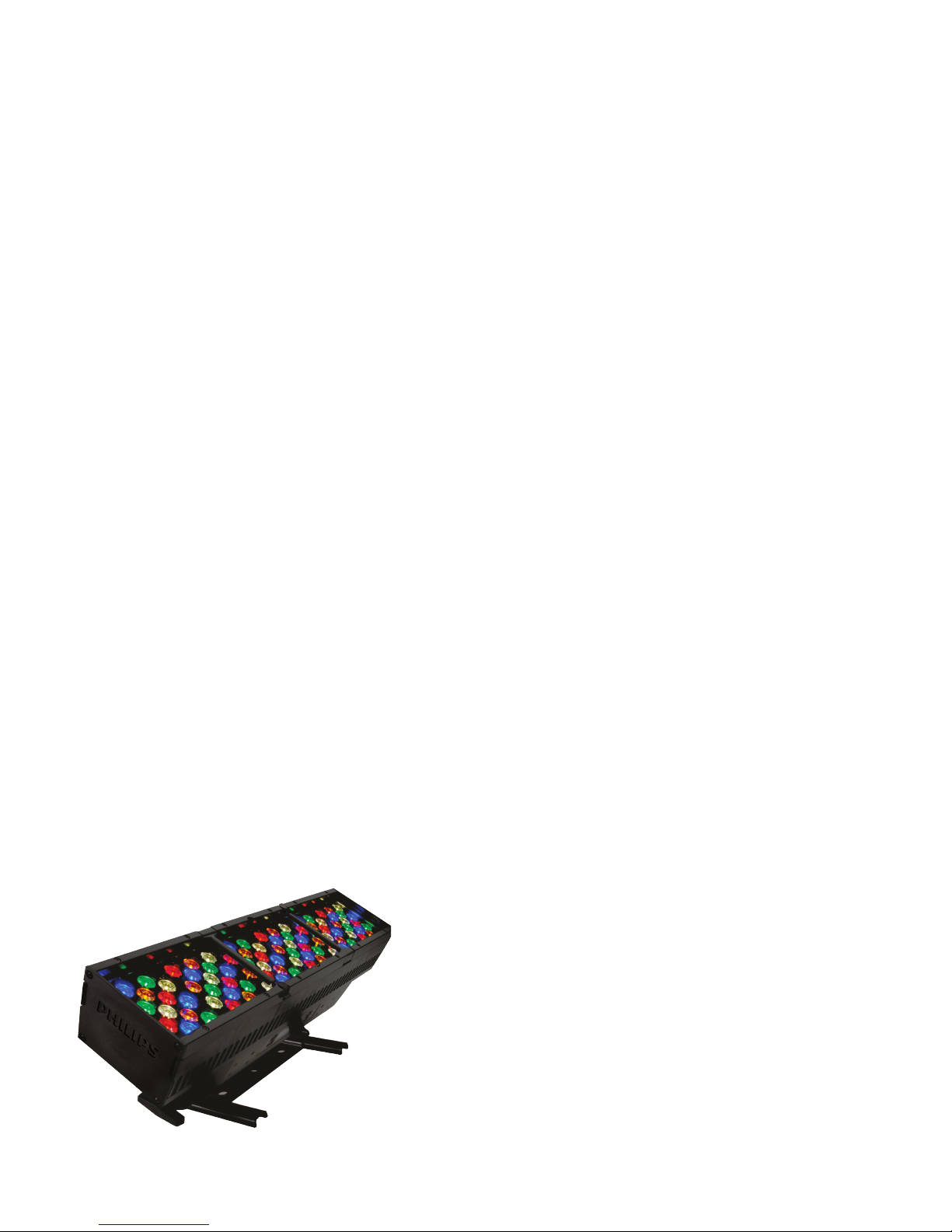
Photometrics
Center Beam fc Beam Width
4.0 ft
8.0 ft
12.0 ft
16.0 ft
20.0 ft
24.0 ft
6378 fc
1594 fc
709 fc
399 fc
255 fc
177 fc
0.9 ft
1.7 ft
2.6 ft
3.4 ft
4.3 ft
5.1 ft
0.9 ft
1.9 ft
2.8 ft
3.7 ft
4.6 ft
5.6 ft
Vert. Spread: 12.2º
Horiz. Spread: 13.2º
Zonal Lumen Summary
Candela Table
15 464 554 591 556 521
35 24 12 11 12 11
45 10 8 8 9 8
55 6 4 3 6 4
75 1 2 1 2 2
Cd: 0
17,167
34,333
51,500
68,667
85,833
103,000
VA: 0º 10º 20º 30º 40º
90º
80º
70º
60º
50º
- 0º H - 90º H
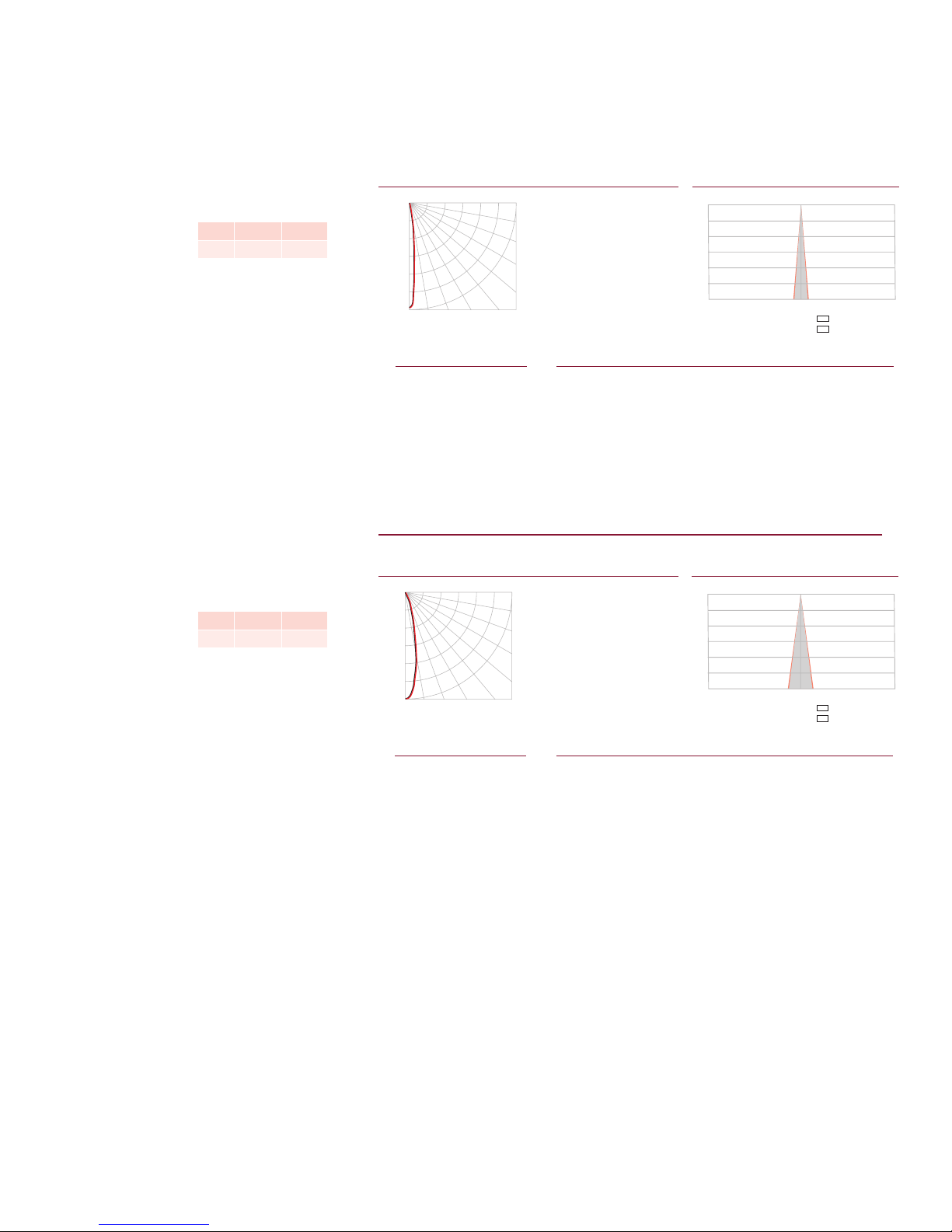
Center Beam fc Beam Width
4.0 ft
8.0 ft
12.0 ft
16.0 ft
20.0 ft
24.0 ft
1794 fc
449 fc
199 fc
112 fc
72 fc
50 fc
1.7 ft
3.4 ft
5.1 ft
6.8 ft
8.4 ft
10.1 ft
1.7 ft
3.4 ft
5.1 ft
6.8 ft
8.5 ft
10.2 ft
Vert. Spread: 23.8º
Horiz. Spread: 24.0º
Zonal Lumen Summary
Candela Table
5 25617 25590 25590 25610 25535
25 1598 1604 1621 1605 1593
45 116 96 85 85 87
85 0 0 0 0 2
Cd: 0
4,833
9,667
14,500
19,333
24,167
29,000
VA: 0º 10º 20º 30º 40º
90º
80º
70º
60º
50º
- 0º H - 90º H
Photometric data is based on test results from an independent NIST traceable testing
lab. IES data is available at www.philipscolorkinetics.com/support/ies.
ColorBlaze TRX
2 ft (610 mm), no spread lens
LED Lumens Efficacy
RGB 7079 23.8
ColorBlaze TRX
2 ft (610 mm), 22° spread lens
LED Lumens Efficacy
RGB 6008 20.2
Polar Candela Distribution
Zonal Lumen
ZONE LUMENS %FIXT
0- 30 6828 96.4
0- 40 6917 97.7
0- 60 7026 99.2
0- 90 7079 100.0
90-180 0 0.0
0-180 7079 100.0
Zonal Lumen
ZONE LUMENS %FIXT
0- 30 5678 94.5
0- 40 5851 97.4
0- 60 5969 99.4
0- 90 6008 100.0
90-180 0 0.0
0-180 6008 100.0
For lux multiply fc by 10.7
Illuminance at Distance
0.0 22.5 45.0 67.5 90.0
0 10204 10204 10204 10204 10204
5 6086 6259 6572 6670 6668
25 52 34 30 29 27
65 4 3 4 5 4
85 0 0 0 0 0
90 0 0 0 0 0
Multiply all candela values by 10
320 ft (97.5 m)
1 fc maximum distance
Coefficients Of Utilization - Zonal Cavity Method
RC 80 70 50 30 10 0
RW 70 50 30 10 70 50 30 10 50 30 10 50 30 10 50 30 10 0
0 119119119119 116116116116 111111111 106106106 102102102 100
1 116114112111 113112110109 108107106 104103103 101100100 98
2 113110107105 111108106104 105103102 102101100 100 99 98 96
3 110107104101 109105103100 103101 99 101 99 97 99 97 96 95
4 108104101 98 107103100 98 101 98 97 99 97 96 97 96 95 93
5 106101 98 96 105101 98 95 99 97 95 98 96 94 96 95 93 92
6 104 99 96 94 103 99 96 94 97 95 93 96 94 92 95 93 92 91
7 102 98 94 92 101 97 94 92 96 93 92 95 93 91 94 92 91 90
8 101 96 93 91 100 95 93 91 95 92 90 94 92 90 93 91 90 89
9 99 94 92 90 99 94 91 89 93 91 89 93 91 89 92 90 89 88
10 98 93 90 88 97 93 90 88 92 90 88 92 90 88 91 89 88 87
Effective Floor Cavity Reflectance: 20%
Illuminance at DistancePolar Candela Distribution
0.0 22.5 45.0 67.5 90.0
0 28710 28710 28710 28710 28710
15 9530 9605 9689 9718 9712
35 280 255 233 228 227
55 55 51 47 51 55
65 29 26 25 27 32
75 6 6 6 9 14
90 0 0 0 0 0
169.5 ft (51.7 m)
1 fc maximum distance
Coefficients Of Utilization - Zonal Cavity Method
RC 80 70 50 30 10 0
RW 70 50 30 10 70 50 30 10 50 30 10 50 30 10 50 30 10 0
0 119119119119 116116116116 111111111 106106106 102102102 100
1 115113111109 113111109107 107105104 103102101 100 99 98 97
2 111107104102 109106103101 103101 99 100 98 97 97 96 95 93
3 108103 99 96 106102 98 96 99 96 94 97 95 93 95 93 91 90
4 104 99 95 92 103 98 94 91 96 93 90 94 91 89 92 90 88 87
5 101 95 91 88 100 94 91 88 93 90 87 91 88 86 90 88 86 84
6 98 92 88 85 97 91 87 85 90 87 84 89 86 84 88 85 83 82
7 96 89 85 82 94 89 85 82 87 84 81 86 83 81 85 83 81 80
8 93 86 82 79 92 86 82 79 85 82 79 84 81 79 83 81 78 77
9 91 84 80 77 90 84 80 77 83 79 77 82 79 77 81 78 76 75
10 88 82 78 75 88 81 78 75 81 77 75 80 77 75 79 77 74 74
Effective Floor Cavity Reflectance: 20%
ColorBlaze TRX Product Guide 3
Page 4
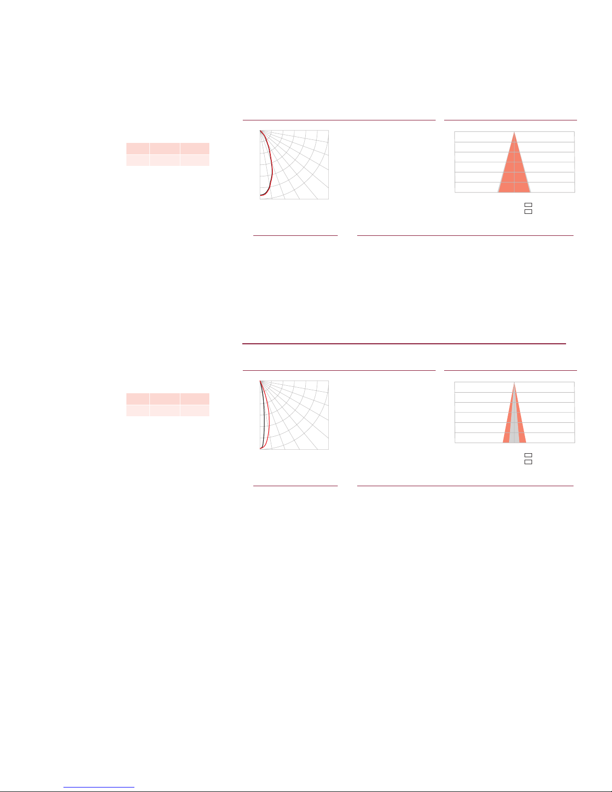
ColorBlaze TRX
Center Beam fc Beam Width
4.0 ft
8.0 ft
12.0 ft
16.0 ft
20.0 ft
24.0 ft
701 fc
175 fc
78 fc
44 fc
28 fc
19 fc
2.9 ft
5.8 ft
8.7 ft
11.7 ft
14.6 ft
17.5 ft
2.8 ft
5.5 ft
8.3 ft
11.0 ft
13.8 ft
16.5 ft
Vert. Spread: 40.0º
Horiz. Spread: 38.0º
Zonal Lumen Summary
Candela Table
65 51 51 50 54 55
Cd: 0
2,000
4,000
6,000
8,000
10,000
12,000
VA: 0º 10º 20º 30º 40º
90º
80º
70º
60º
50º
- 0º H - 90º H
Center Beam fc Beam Width
4.0 ft
8.0 ft
12.0 ft
16.0 ft
20.0 ft
24.0 ft
2431 fc
608 fc
271 fc
152 fc
97 fc
68 fc
1.0 ft
1.9 ft
2.9 ft
3.8 ft
4.8 ft
5.8 ft
2.1 ft
4.2 ft
6.4 ft
8.5 ft
10.6 ft
12.7 ft
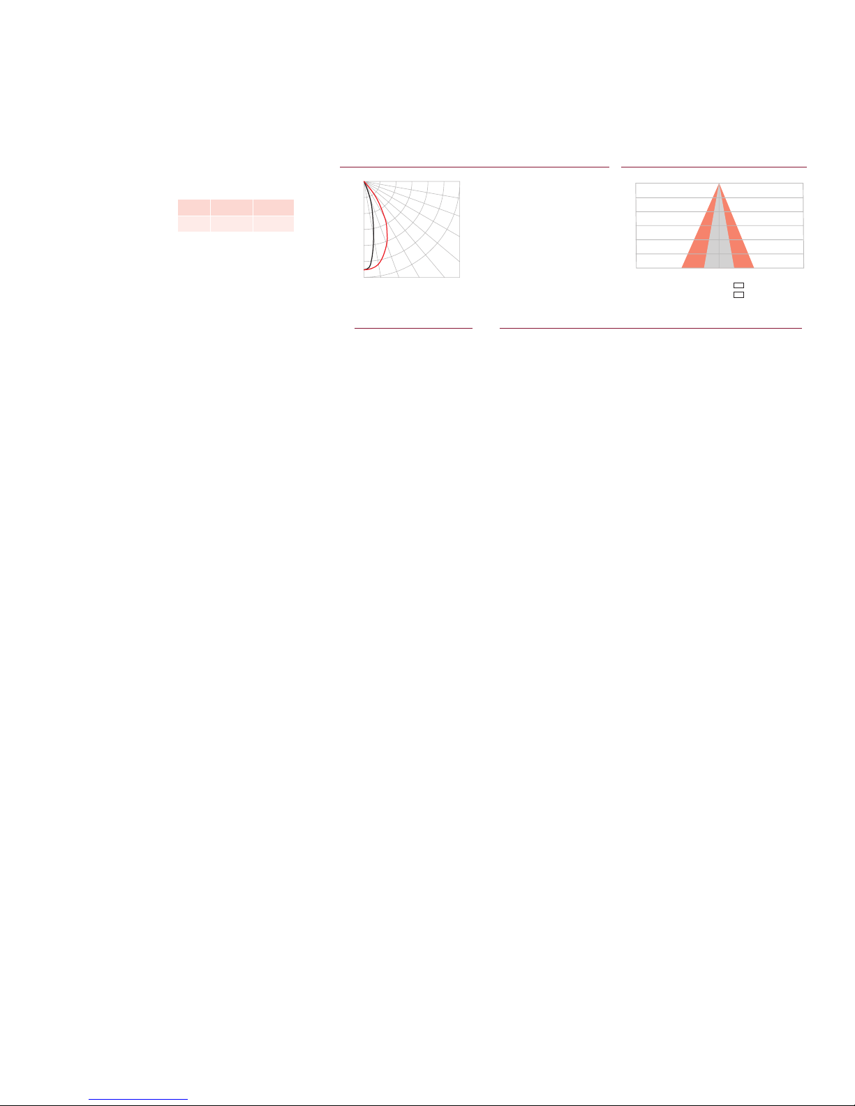
Vert. Spread: 13.7º
Horiz. Spread: 29.7º
Zonal Lumen Summary
Candela Table
35 158 160 158 360 928
45 71 73 76 103 232
55 37 38 43 52 114
65 19 19 20 26 69
75 3 5 6 10 31
85 0 0 0 0 3
Cd: 0
6,500
13,000
19,500
26,000
32,500
39,000
VA: 0º 10º 20º 30º 40º
90º
80º
70º
60º
50º
- 0º H - 90º H
2 ft (610 mm), 32° spread lens
LED Lumens Efficacy
RGB 6008 19.7
Polar Candela Distribution
Zonal Lumen
ZONE LUMENS %FIXT
0- 30 4678 79.7
0- 40 5428 92.5
0- 60 5791 98.7
0- 90 5868 100.0
90-180 0 0.0
0-180 5868 100.0
Illuminance at Distance
0.0 22.5 45.0 67.5 90.0
0 11208 11208 11208 11208 11208
5 10833 10812 10767 10734 10684
15 7699 7649 7517 7374 7302
25 3684 3651 3554 3422 3356
35 1193 1190 1158 1108 1081
45 326 321 313 305 300
55 116 111 107 110 110
75 19 20 20 22 25
85 1 1 1 2 4
90 0 0 0 0 0
106 ft (32.3 m)
1 fc maximum distance
Coefficients Of Utilization - Zonal Cavity Method
RC 80 70 50 30 10 0
RW 70 50 30 10 70 50 30 10 50 30 10 50 30 10 50 30 10 0
0 119119119119 116116116116 111111111 106106106 102102102 100
1 114111109107 111109107105 105103102 101100 99 98 97 96 94
2 109104100 97 106102 99 96 99 96 94 96 94 92 93 92 90 88
3 104 98 93 89 102 96 92 89 94 90 87 91 88 86 89 87 85 83
4 99 92 87 83 97 91 86 83 89 85 82 87 83 81 85 82 80 78
5 95 87 82 78 93 86 81 77 84 80 77 83 79 76 81 78 75 74
6 91 82 77 73 89 82 76 73 80 76 72 79 75 72 78 74 71 70
7 87 78 73 69 85 78 72 69 76 72 68 75 71 68 74 70 68 66
8 83 74 69 65 82 74 69 65 73 68 65 72 68 65 71 67 64 63
9 80 71 66 62 79 71 65 62 70 65 62 69 65 61 68 64 61 60
10 77 68 63 59 76 67 62 59 67 62 59 66 62 59 65 61 58 57
Effective Floor Cavity Reflectance: 20%
ColorBlaze TRX
2 ft (610 mm), 32° x 12° spread lens
LED Lumens Efficacy
RGB 6018 20.2
Zonal Lumen
ZONE LUMENS %FIXT
0- 30 5639 93.7
0- 40 5850 97.2
0- 60 5979 99.4
0- 90 6018 100.0
90-180 0 0.0
0-180 6018 100.0
For lux multiply fc by 10.7
Illuminance at DistancePolar Candela Distribution
0.0 22.5 45.0 67.5 90.0
0 38890 38890 38890 38890 38890
5 26212 27341 30371 34411 36000
15 2513 3228 6149 13126 19131
25 330 333 604 2448 5242
90 0 0 0 0 0
197 ft (60 m)
1 fc maximum distance
Coefficients Of Utilization - Zonal Cavity Method
RC 80 70 50 30 10 0
RW 70 50 30 10 70 50 30 10 50 30 10 50 30 10 50 30 10 0
0 119119119119 116116116116 111111111 106106106 102102102 100
1 115113111109 113111109108 107106104 103102101 100 99 98 97
2 111108105102 109106103101 103101 99 100 98 97 97 96 95 93
3 108103100 97 106102 99 96 99 97 95 97 95 93 95 93 92 91
4 105 99 95 92 103 98 95 92 96 93 91 94 92 90 93 91 89 88
5 102 96 92 89 100 95 91 89 93 90 88 92 89 87 91 88 86 85
6 99 93 89 86 98 92 88 86 91 87 85 90 87 84 88 86 84 83
7 96 90 86 83 95 89 86 83 88 85 82 87 84 82 86 84 82 81
8 94 87 83 81 93 87 83 81 86 83 80 85 82 80 84 82 80 79
9 92 85 81 79 91 85 81 78 84 81 78 83 80 78 83 80 78 77
10 89 83 79 77 89 83 79 76 82 79 76 81 78 76 81 78 76 75
Effective Floor Cavity Reflectance: 20%
ColorBlaze TRX Product Guide4
Page 5
ColorBlaze TRX
Center Beam fc Beam Width
4.0 ft
8.0 ft
12.0 ft
16.0 ft
20.0 ft
24.0 ft
637 fc
159 fc
71 fc
40 fc
25 fc
18 fc
2.0 ft
4.0 ft
6.1 ft
8.1 ft
10.1 ft
12.1 ft
4.8 ft
9.6 ft
14.4 ft
19.2 ft
24.0 ft
28.8 ft
Vert. Spread: 28.4º
Horiz. Spread: 62.0º
Zonal Lumen Summary
Candela Table
15 4684 5118 6386 8006 8779
25 1227 1527 2693 5041 6621
35 270 342 762 2362 4064
45 112 128 211 807 1877
65 33 38 47 84 191
Cd: 0
1,833
3,667
5,500
7,333
9,167
11,000
VA: 0º 10º 20º 30º 40º
90º
80º
70º
60º
50º
- 0º H - 90º H
2 ft (610 mm), 60° x 32° spread lens
LED Lumens Efficacy
RGB 5815 19.5
Polar Candela Distribution
Zonal Lumen
ZONE LUMENS %FIXT
0- 30 4213 72.4
0- 40 5111 87.9
0- 60 5715 98.3
0- 90 5815 100.0
90-180 0 0.0
0-180 5815 100.0
For lux multiply fc by 10.7
Illuminance at Distance
0.0 22.5 45.0 67.5 90.0
0 10197 10197 10197 10197 10197
5 9421 9507 9713 9935 9992
55 63 70 92 238 642
75 11 14 18 28 56
85 0 0 1 3 3
90 0 0 0 0 0
101 ft (30.8 m)
1 fc maximum distance
Coefficients Of Utilization - Zonal Cavity Method
RC 80 70 50 30 10 0
RW 70 50 30 10 70 50 30 10 50 30 10 50 30 10 50 30 10 0
0 119119119119 116116116116 111111111 106106106 102102102 100
1 113111108106 111109106104 105103101 101 99 98 97 96 95 93
2 108103 99 96 106101 98 95 98 95 92 95 93 90 92 90 89 87
3 103 96 91 87 101 95 90 87 92 88 85 90 87 84 88 85 83 81
4 98 90 85 80 96 89 84 80 87 82 79 85 81 78 83 80 77 76
5 93 85 79 75 91 84 78 74 82 77 74 80 76 73 79 75 72 71
6 88 80 74 70 87 79 73 69 77 73 69 76 72 69 75 71 68 67
7 84 75 69 65 83 75 69 65 73 68 65 72 68 65 71 67 64 63
8 81 71 66 62 79 71 65 61 70 65 61 69 64 61 68 64 61 59
9 77 68 62 58 76 67 62 58 66 61 58 65 61 58 65 61 58 56
10 74 64 59 55 73 64 59 55 63 58 55 63 58 55 62 58 55 53
Effective Floor Cavity Reflectance: 20%
ColorBlaze TRX Product Guide 5
Page 6
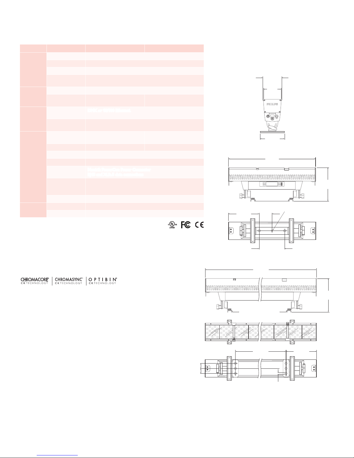
Specications
55 in
(1402 mm)
8.5 in
(216 mm)
72 in
(1829 mm)
4.9 in
(124 mm)
5.25 in
(133 mm)
.5 in
(12.7 mm)
6.7 in
(170 mm)
9.3 in
(236 mm)
4.9 in
(124 mm)
5.25 in
(133 mm)
6.7 in
(170 mm)
Due to continuous improvements and innovations, specifications may change without notice.
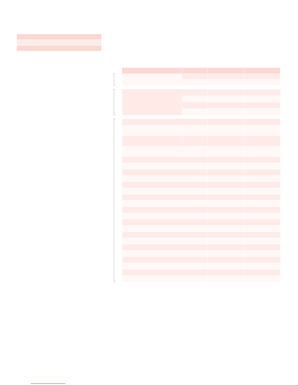
Item Specication 2 ft (610 mm) 6 ft (1.8 m)
Beam Angle 10° native (no spread lens)
LED Channels Red / Green / Blue / Amber / White
Output
Electrical
Control
Physical
Certication
and Safety
* Lumen measurement complies with IES LM-79-08
† L50 = 50% lumen maintenance (when light output drops below 50% of initial
output). Ambient luminaire temperatures specied. Lumen maintenance
calculations are based on lifetime prediction graphs supplied by LED source manufacturers. Calculations
for white-light LED xtures are based on measurements that comply with IES LM-80-08 testing
procedures. Refer to www.philipscolorkinetics.com/suppor t/appnotes/lm-80-08.pdf for more
information.
Lumens* 7079 (2 ft length, RGBAW channels full on)
Lumen Maintenance†
50,000 hours L50 @ 25° C
35,000 hours L50 @ 50° C
Input Voltage 100 – 240 VAC, auto-switching, 50 / 60 Hz
Power Consumption
Interface
Control System
Dimensions
(Height x Width x Depth)
315 W maximum at full output,
steady state
DMX or 10/100 Ethernet. Fixture rmware addressable 8- and
16-bit control, RGBAW, and RGB modes.
Philips full range of controllers, including Video System Manager Pro
and Light System Manager, or third-party controllers
9.3 x 24 x 6.7 in
(236 x 610 x 170 mm)
930 W maximum at full output,
steady state
9.3 x 72 x 6.7 in
(236 x 1829 x 170 mm)
Weight 16.2 lb (7.3 kg) 43 lb (19.5 kg)
Housing Extruded aluminium and polymer, black nish
Lens Clear polycarbonate
Fixture Connections
Neutrik PowerCon Power Connector
RJ45 and XLR-5 data connections
-40° – 122° F (-40° – 50° C) Operating
Temperature Ranges
32° – 122° F (0° – 50° C) Startup
-40° – 122° F (-40° – 50° C) Storage
Humidity 0 – 95%, non-condensing
Certication UL / cUL, FCC Class A, CE
Environment Dry Location, IP20
8.5 in
(217 mm)
3.5 in
(89 mm)
72 in
(1829 mm)
5.25 in
(133 mm)
4.9 in
(124 mm)
6.7 in
(170 mm)
24 in
(610 mm)
7 in
(178 mm)
.51 in
(Ø13 mm)
9.3 in
(236 mm)
9.3 in
(236 mm)
ColorBlaze TRX Product Guide6
1.4 in
(35 mm)
1.4 in
(35 mm)
55 in
(1402 mm)
.5 in
(12.7 mm)
8.5 in
(216 mm)
Page 7
Included in the box
ColorBlaze TRX xture
Neutrik PowerCon connector
Ferrite core for EMI suppression
ColorBlaze TRX eld replaceable units
E Field replaceable units (FRUs) must be
installed by trained / qualified personnel in
accordance with procedures detailed in the
ColorBlaze TR X Service Manual.
Fixtures, Lenses, and Replacement Parts
ColorBlaze TRX fixtures are part of a complete system which includes a full range of
Philips controllers, including Video System Manager Pro, Light System Manager, and
iPlayer 3, or a third-party controller, and RJ45 or XLR-5 data cables for connecting
xtures together in series or to controllers, and power cables using Neutrik
PowerCon connectors for connecting xtures to power, or for connecting multiple
xtures to a single circuit.
Item Type Item Number Philips 12NC
ColorBlaze TRX xtures ColorBlaze TRX
Spread lenses Spread Lenses, 2 ft
LED board assembly 120-000127-00 910503701963
Power supply / lter board assembly
with battery holders
Power supply / lter board assembly
without battery holders
Control board with OLED display, UI components,
and UI buttons
Fan assembly 120-000130-00 910503701967
Primary lens, 2 ft 120-000131-00 910503701968
Primary lens, 6 ft 120-000131-01 910503701969
LED board carrier 120-000132-00 910503701970
Secondary lens rail pair, 2 ft 120-000133-00 910503701971
Secondary lens rail pair, 6 ft 120-000133-01 910503701972
Lens clip assembly, pair 120-000134-00 910503701973
Diffuser spacer assembly, pair 120-000134-01 910503701974
Top end cap assembly, pair 120-000135-00 910503701974
Yoke with mounting feet (for 2 ft unit only) 120-000136-00 910503701975
Trunion with mounting foot, pair 120-000137-00 910503701976
Thermoplastic T-handle, pair 120-000138-00 910503701977
End cap rotation bracket assembly, input side 120-000139-00 910503701978
End cap rotation bracket assembly, output side 120-000139-01 910503701789
Input connector board assembly 120-000140-00 910503701979
Output connector board assembly 120-000140-01 910503701980
Optic tray assembly with optics, pair 120-000141-00 910503701981
Back cover, 2 ft 120-000142-00 910503701982
Back cover, 6 ft 120-000142-01 910503701983
Power distribution board assembly, 2 ft section 120-000143-00 910503701984
2 ft 116-000028-00 910503701741
6 ft 116-000028-01 910503701742
22° 120-000109-00 910503701959
32° 120-000109-01 910503701960
60° x 32° 120-000109-02 910503701961
32° x 12° 120-000109-03 910503701962
Center unit 120-000128-00 910503701964
End units 120-000128-01 910503701965
120-000129-00 910503701966
Use Item Number when ordering in North America.
ColorBlaze TRX Product Guide 7
Page 8

Installation
ColorBlaze TRX fixtures have integrated power supplies and onboard menus, located
on the front of the fixture, for addressing and other functions. These features,
along with remote configuration capabilities and flexible mounting hardware, make
ColorBlaze TRX fixtures easy to set up, configure, and tear down.
Owner / User Responsibilities
It is the responsibility of the contractor, installer, purchaser, owner, and user to
install, maintain, and operate ColorBlaze TRX fixtures in such a manner as to comply
with all applicable codes, state and local laws, ordinances, and regulations. Consult
with the appropriate electrical inspector to ensure compliance.
Planning Your Installation
ColorBlaze TRX is a highly exible, capable LED lighting xture with multiple points
of control. Your approach to addressing, conguring, and mounting ColorBlaze TRX
xtures will differ depending on your situation:
▪ In simple installations using pre-programmed light shows, a lighting board, or
DMX controller, you may not need to perform any onboard or per-xture
addressing.
▪ In rental, touring, and other temporary installations, it’s often advantageous to
address and congure xtures in a preparation area before hanging or mounting
them. Doing so requires you to power up the xtures, congure them with the
onboard controls, and install any spread lenses or other accessories. At the
installation site, the xtures must be hung or mounted and connected to power.
E Refer to t he ColorBlaze TRX Installation
Instructions for specif ic warning and caution
statements.
E You can conf igure ColorBlaze TRX f ixtures
on battery power, without connecting them to
AC power.
In architectural applications where fixtures are mounted permanently against flat
surfaces, in niches, or in other areas that may be difficult to access, we strongly
recommend configuring ColorBlaze TRX fixtures before installing them.
▪ In permanent installations, xtures are likely to be installed in xed locations
and recongured for different purposes and events. In such situations, you can
congure ColorBlaze TRX xtures in position using the onboard controls, or you
can perform certain congurations over the lighting network using a personal
computer and QuickPlay Pro addressing and conguration software.
Because it’s the most common situation, the installation sections that follow describe
the process for a rental or touring installation, where fixtures are addressed and
configured in a preparation area, then hung at the installation site.
DMX or Ethernet?
ColorBlaze TRX fixtures can accept either DMX or Ethernet (KiNET) data
input. Because of addressing limitations, DMX is appropriate for relatively simple
installations, or for light shows in which multiple fixtures operate in unison. A DMX
universe consists of 512 addresses, while ColorBlaze TR X fixtures can consume from
3 to 216 DMX addresses each, depending on length and configuration.
Because it is not subject to DMX addressing limitations, Ethernet is the preferred
environment for intricate, color-changing light shows and video displays, in which
each fixture node must be controlled individually. In an Ethernet lighting network,
each ColorBlaze TRX fixture effectively functions as its own universe, identified by
the fixture's unique IP address. Depending on your controller, Ethernet installations
can have tens of thousands of unique, individually controllable nodes — in some
cases, hundreds of thousands.
A typical DMX installation uses a DMX controller such as iPlayer 3, or a third-party
DMX lighting control board. ColorBlaze TRX devices can be connected in series to a
controller's DMX output port. The number of fixture runs is limited by the number
of DMX output ports on each controller.
ColorBlaze TRX Product Guide8
Page 9
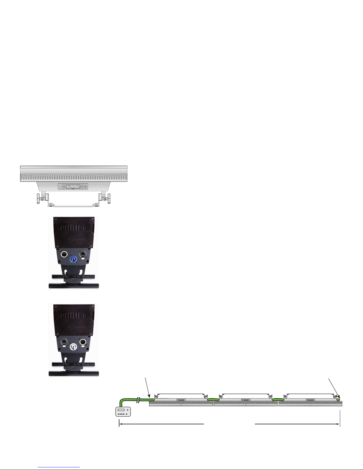
Inputs Outputs
Onboard controls
A typical Ethernet installation uses one or more Ethernet switches, and an Ethernet
controller such as Light System Manager or Video System Manager Pro. You can
connect a series of up to 15 ColorBlaze TRX xtures to each available Ethernet port.
Creating a Lighting Design Plan
Regardless of the details of your installation, it’s good practice to create a
lighting design plan that identifies your fixtures, details their addresses and other
configuration information, and identifies their locations in relation to other required
hardware. For complex installations displaying light shows with dynamic effects, such
a lighting design plan is essential.
To create a lighting design plan, determine the appropriate location of each
ColorBlaze TRX fixture in relation to power sources and controllers. On an
architectural diagram or other diagram that shows the physical layout of the
installation, identify the locations of all controllers, xtures, power sources, and
cables. To streamline installation and aid in light show programming, you can afx
a label identifying the order or placement in the installation to an inconspicuous
location on each ColorBlaze TRX xture’s housing.
Keep the following considerations in mind when planning your installation:
• The integrated, auto-switching power supply automatically adjusts to any 50 / 60
Hz power source from 100 – 240 VAC. Each ColorBlaze TR X xture includes a
Neutrik PowerCon connector to which you can connect a power cable with ying
leads appropriate for your geographic location.
• You can connect ColorBlaze TRX data control in series, using XLR-5 data cables
for DMX, or Ethercon or RJ45 for Ethernet.
Power and data inputs
Power and data outputs
• ColorBlaze TRX xtures can work as a single pixel, or you can set xtures to have
multiple segments that display different colors simultaneously for dynamic effects.
Segment lengths can be as small as 4 in (102 mm) or as large as the entire xture
— 2 ft (610 mm) or 6 ft (1.8 m). When installing xtures end-to-end, you can
create virtual segments that span multiple xtures.
• You can mix 2 ft and 6 ft ColorBlaze TR X xtures in a single run. A mixture of
xture lengths can offer exibility in architectural applications where you need to
install xtures around corners or in conned areas.
• Using a combination of Neutrik PowerCon power in and power out connectors,
you can connect a run of multiple ColorBlaze TRX xtures from a single power
source.
Data Conguration Guidelines
You can mount ColorBlaze TRX fixtures end-to-end, or you can space them
however you wish, so long as you follow these data configuration guidelines:
• In DMX networks using shielded XLR-5 data cables, maximum data run lengths
are 1,640 ft (500 m). The maximum number of DMX devices that can be
connected in series is 32. We recommend using DMX repeaters for runs that
exceed the maximum length, as well as for runs of more than 32 DMX devices
connected in series.
RJ45 or XLR-5
Data cables
DMX
Terminator
1640 ft Maximum DMX
(500 m)
ColorBlaze TRX Product Guide 9
Page 10
• In Ethernet networks, maximum data cables lengths are 328 ft (100 m) between
910503701741
116-000028-00
111000 22b342-45/567
123-4567 8 91 01
1046BMG0001
12345678
00
0000
Ethernet devices without a repeater (for example, controller to switch, switch
to ColorBlaze TRX xture, or xture to xture). You can connect up to 15
ColorBlaze TRX xtures in series.
Power Conguration Guidelines
For proper power management, ColorBlaze TRX fixtures should be installed on a
separate power circuit of 20 A maximum. We recommend using 3-conductor 12
AWG (3.3 mm
2
) stranded copper wire for power cables.
You can connect multiple ColorBlaze TRX in series on a single circuit. The maximum
number of fixtures each circuit can support depends on fixture power consumption
(fixture length), voltage, and power cable lengths. The table to the right lists
maximum run lengths for fixtures and power cables per circuit at different voltages.
Keep in mind that these gures, provided as a guideline, are accurate for the specied
conguration only. Changing the conguration can affect the run lengths.
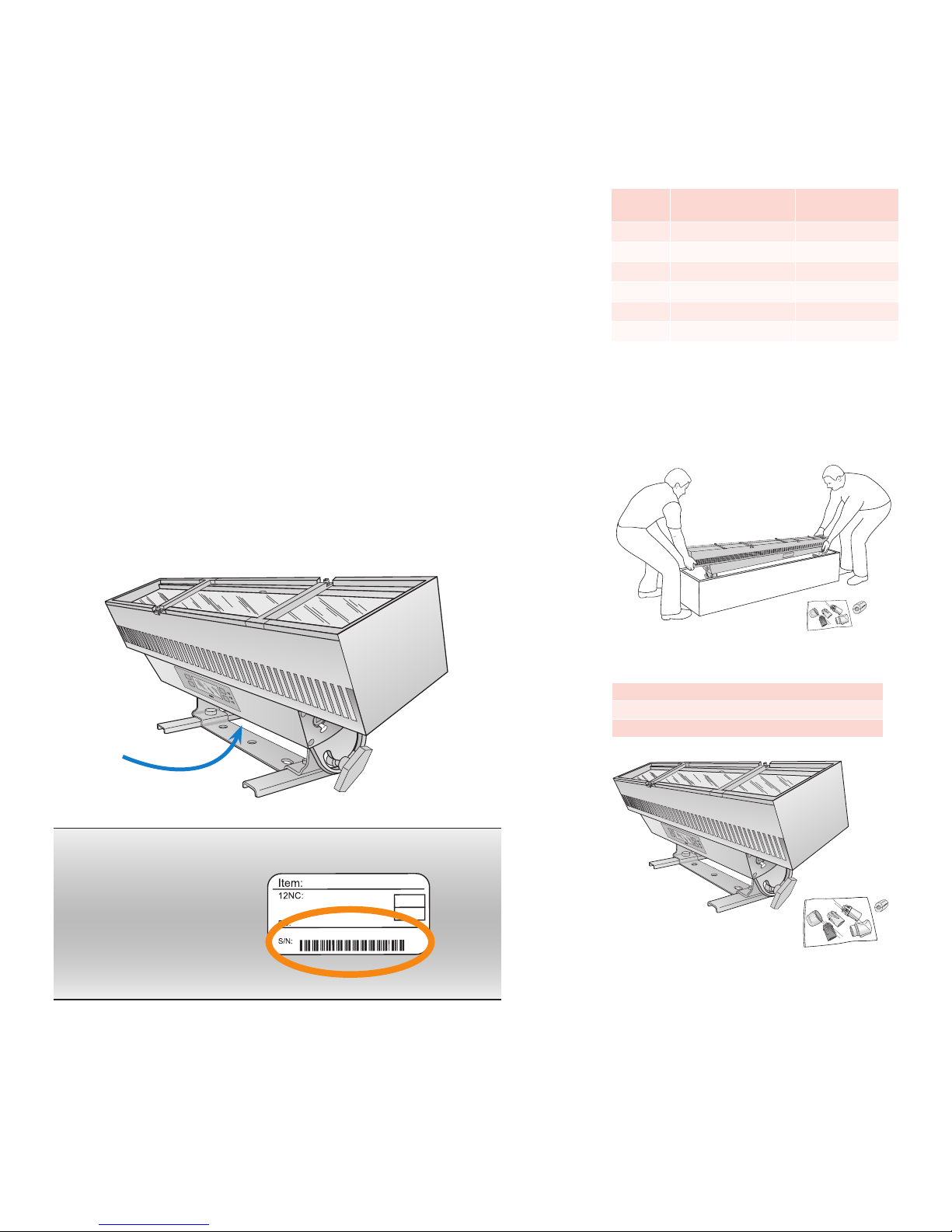
Unpack Fixtures
1. As you unpack ColorBlaze TRX, carefully inspect the box and contents for any
damage that may have occurred in transit. Because each 6 ft ColorBlaze TRX
fixture is bulky and weighs 43 lb (19.5 kg), you may need two people to lift the
fixture out of the box.
2. Each ColorBlaze TRX xture is assigned a date code and unique serial number.
We recommend recording the serial numbers and date codes in a layout grid
(typically a spreadsheet or list) to aid in servicing and troubleshooting.
Maximum power run lengths
Voltage
100 VAC 8 100
120 VAC 12 100
208 VAC 20 200
220 VAC 22 175
230 VAC 22 200
240 VAC 24 200
Assumes xtures installed in series on a 20 A circuit with 12 AWG
power cables. Maximum number of xtures can include any
combination of 2 f t and 6 ft xtures. Maximum feet of power
cables = leader cable + jumper cables.
Maximum Feet of
ColorBlaze TRX Fixtures
Maximum Feet of
Power Cables
3. Assign each xture to a position in the lighting design plan.
4. To streamline installation and aid in light show programming, you can afx a label
identifying the order or placement in the installation to an inconspicuous location
on each light xture’s housing.
ColorBlaze TRX Product Guide10
Included in the box
ColorBlaze TRX xture
Neutrik PowerCon connector
Ferrite core for EMI suppression
Page 11
Connect Fixture to Power
ColorBlaze TRX has integrated, auto-switching power supplies that automatically
adjust to any 50 / 60 Hz power source from 100 – 240 V. ColorBlaze TRX fixtures
connect directly to line power using the included Neutrik PowerCon connector and
the appropriate length of power cable. We recommend using 3-conductor 12 AWG
(3.3 mm
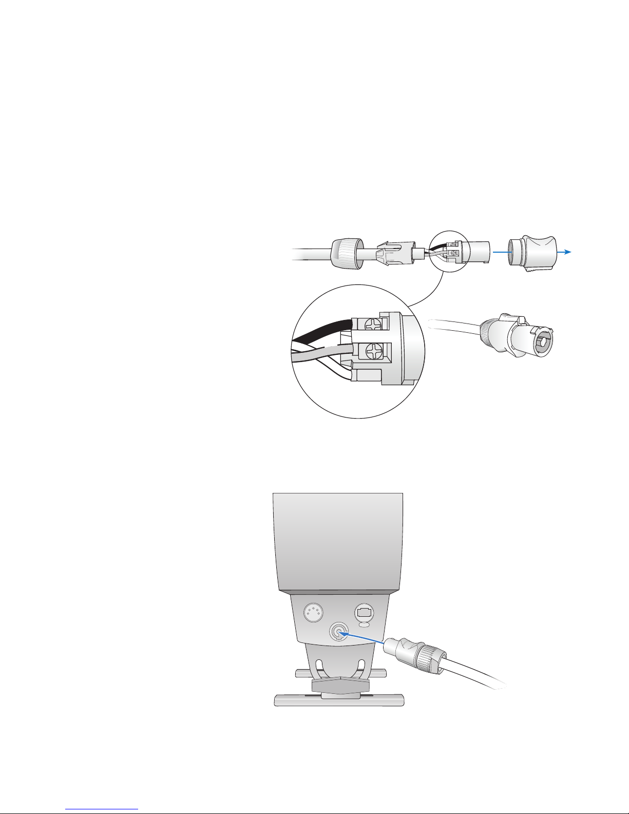
1. Unpack the xture, and place it in a staging area or other location where the
2. Connect the appropriate length of 3-wire power cable from line power to
2
) stranded copper wire
power and data ports on the ends of the xture are readily accessible.
the Neutrik PowerCon connector. Following the connector manufacturer’s
instructions, assemble the connector, connecting ground (earth), line, and
neutral.
.2 – .6 in Ø
(5 – 15 mm Ø)
12 AWG
(3.3 mm2)
L
z
N
3. Insert the assembled power connector into the power input port on the input
side of the xture (with the onboard controls facing you, the left end of the
xture).
3
2
4
5
1
PUSH
From line power
ColorBlaze TRX Product Guide 11
Page 12
Address and Congure the Fixtures
Make sure the power is ON before addressing and configuring fixtures.
When in DMX / Ethernet mode, each ColorBlaze TRX fixture uses a set of
sequential DMX addresses. A ColorBlaze TRX fixture uses from 3 to 216 DMX
addresses, depending on color control mode (3-channel or 5-channel DMX input),
fixture resolution (8-bit or 16-bit), fixture length (2 ft or 6 ft), segment size (ranging
from 4 in to the total fixture length), and whether the intensity channel is enabled or
disabled.
In 8-bit mode, each segment uses one DMX address per channel, while in 16-bit
mode each segment uses two DMX addresses per channel, one for coarse control
and one for fine control. The coarse channel allows values in multiples of 256, while
the fine channel adds 256 additional values to each coarse channel value, resulting in
a total of 65,536 individual steps or settings (256 x 256). Channel assignments per
segment are as follows:
Channels Per Node
RGB in / out and RGB -> RGBAW (3-channel RGB input)
8-Bit Mode
16-Bit Mode
Red Coarse Red Fine
1 2 3 4
Red Green Blue Intensity
1 2 3 4 5 6 7 8
Green
Coarse
Green Fine
Blue
Coarse
Blue Fine
Intensity Channel
Intensity
Coarse
Enabled
Intensity
Fine
RGBAW in / out (5-channel RGBAW input)
8-Bit Mode
16-Bit Mode
1 2 3 4 5 6
Red Green Blue Amber White Intensity
1 2 3 4 5 6 7 8 9 10 11 12
Red
Coarse
Red
Fine
Green
Coarse
Green
Fine
Blue
Coarse
Blue
Fine
Amber
Coarse
Each ColorBlaze TRX fixture is factory-addressed with a DMX starting address of 1.
Sequential DMX addresses are automatically assigned to the fixture beginning with
the starting address. For instance, if you set a 2 ft fixture to RGB in / out mode,
8-bit operation, segment size of 24 in, and DMX starting address 73, the fixture is
automatically assigned three DMX addresses, 73 – 75. If you set a 2 ft fixture to
RGBAW in / out mode, 16-bit operation, segment size of 4 in, and DMX starting
address 400, the fixture is automatically assigned 60 DMX addresses, 400 – 459.
Make sure that the DMX starting address allows enough DMX addresses for all of
the fixture’s segments, or the fixture will not function properly. For example, a 2
ft fixture with 4 in segments set to RGBAW in / out at 8-bit resolution requires 30
DMX addresses — 5 addresses per each of six segments. Therefore, the fixture's
DMX starting address should be 483 or lower.
Addressing in a DMX Lighting Network
Since each DMX universe is limited to 512 DMX addresses, you must take care to
configure and address your fixtures to ensure that enough unique addresses are
available to support your light show designs.
Amber
Fine
White
Coarse
White
Fine
E Terminology for individually controllable
LED lighting units varies and can become
confusing. In general, an individually
controllable lighting unit is referred to as
a node. A xture can function as a single
node, or it can contain multiple nodes.
ColorBlaze TRX is unusual because it can be
segmented into one or more nodes.
In video displays, individually controllable
nodes are often referred to as pixels. A pixel
can be a single-node xture, or a segment of
a multiple-node xture.
Intensity Channel
Enabled
Intensity
Coarse
Intensity
Fine
For lighting designs where fixtures work in unison, all fixtures can be assigned the
same DMX starting address. For light show designs that display different output on
different fixtures or segments simultaneously, you must address your fixtures such
that the DMX addresses assigned to each segment are unique and do not overlap.
ColorBlaze TRX Product Guide12
Page 13

(2 ft)
(6 ft)
24 in segments
9 ft segments
ColorBlaze TRX
(2 ft)
ColorBlaze TRX
(6 ft)
24 in segments
9 ft segments
12549
ColorBlaze TRX
(6 ft)
DMX starting addresses
(2 ft)
ColorBlaze TRX
(6 ft)
ColorBlaze TRX
(6 ft)
ColorBlaze TRX
(6 ft)
ColorBlaze TRX
(6 ft)
ColorBlaze TRX
(6 ft)
For example, in a series of three 2 ft fixtures, each with 4 in segments, RGB in / out,
8-bit resolution, and the intensity channel enabled, you can ensure that each fixture
segment is uniquely addressed by setting the DMX starting address of the first
fixture to 1, the starting address of the second fixture to 25 (1 + 24), and the starting
address of the third fixture to 49 (25 + 24).
ColorBlaze TRX
ColorBlaze TRX
ColorBlaze TRX
Addressing in an Ethernet Lighting Network
Because it eliminates the addressing limitations of DMX, Ethernet is preferred for
lighting installations that display intricate effects requiring hundreds or thousands of
individually addressable nodes.
In Ethernet lighting networks, each fixture effectively functions as its own DMX
universe. Ethernet lighting controllers identify each ColorBlaze TRX fixture by an IP
address. As long all ColorBlaze TRX IP addresses are unique within an installation,
the set of DMX addresses assigned to a given fixture is unique within the installation,
regardless of the fixture’s DMX starting address.
Some Notes About Fixture Segments
Each ColorBlaze TRX fixture is factory-addressed to have a segment size of 4 in
(highest resolution) and a DMX starting address of 1. For complex installations
where you set different numbers of groups on different xtures, it’s good practice to
notate each xture’s group setting on the lighting design plan.
Keep the following considerations in mind when setting the number of fixture
groups:
• You can mix 2 ft and 6 ft ColorBlaze TR X fixtures in the same series while
maintaining consistent segment lengths of 4 in, 8 in, 12 in, or 24 in.
ColorBlaze TRX
(6 ft)
E To streamline conguration and light
show programming, note each xture's IP
address, if applicable, and the DMX starting
address of each xture segment, on your
lighting design plan.
ColorBlaze TRX
(6 ft)
ColorBlaze TRX
ColorBlaze TRX
• If you install fixtures of the same length end to end, you can create virtual
segments that span multiple fixtures. For example, you can create virtual 9 ft
segments with 6 ft ColorBlaze TRX fixtures by alternating fixtures with 72 in and
36 in segment sizes.
ColorBlaze TRX
(6 ft)
ColorBlaze TRX
(6 ft)
ColorBlaze TRX
(6 ft)
Addressing and Conguration Methods
You can manually set the color control mode, fixture resolution, segment size,
intensity channel setting, and DMX starting address of a ColorBlaze TRX fixture
using the onboard menus. Refer to “Using the ColorBlaze TRX Onboard Menus,”
beginning on page 23, for details.
You can also remotely address and configure ColorBlaze TRX fixtures using
QuickPlay Pro addressing and configuration software with a computer connected to
your lighting network. Refer to “Addressing and Configuring ColorBlaze TRX with
QuickPlay Pro” on page 37 for details.
ColorBlaze TRX Product Guide 13
Page 14

Using the Intensity Channel
Enabling the intensity channel lets you adjust the brightness of all LED channels
proportionally using a fader on a DMX console. For example, you can set a desired
color, then adjust the brightness with the assigned fader while maintaining the color
value.
When you enable the intensity channel, each ColorBlaze TRX node consumes an
additional DMX address in 8-bit mode and two additional DMX addresses in 16-bit
mode (as shown in the table on page 12). Make sure that your addressing scheme
accounts for the additional DMX addresses that the intensity channel requires.
You can use the Single-Channel Fixture icon in ColorPlay 3 (version 1.10 and higher)
to represent and control the intensity channel in a ColorPlay 3 light show. Refer to
the ColorPlay 3 User Guide for more information.
Options for Controlling ColorBlaze TRX
Fixtures
In addition to standard control schemes using DMX- or Ethernet-based lighting
consoles and controllers, ColorBlaze TRX offers a number of control options
designed to support architectural, theatrical, and portable lighting applications.
Standalone Mode
By default, the input source of a ColorBlaze TRX xture is DMX / Ethernet. When in
DMX / Ethernet mode, ColorBlaze TRX listens for and responds to DMX or Ethernet
data transmitted to the lighting network by a console or controller.
E For instructions on enabling and
disabling the intensity channel, refer to
"Enabling and Disabling the Intensity
Channel" on page 31.
You can change the input source of ColorBlaze TRX xture to Standalone. In
Standalone mode, a ColorBlaze TRX xture ignores DMX and Ethernet data input
and displays either a pre-set show or a ColorPlay 3 show stored on the xture's SD
card. ColorBlaze TRX offers three pre-set shows — Fixed Color, Color Wash, and
Chasing Rainbow — which you can congure using the xture's on-board menus.
You can download light shows and triggers onto a xture's installed SD card from
ColorPlay 3, light show authoring and conguration software from Philips Color
Kinetics. ColorPlay 3 is bundled with the iPlayer 3 DMX controller, and is also
available as a free download from the Philips Color Kinetics website.
To download ColorPlay 3 light shows and triggers to the ColorBlaze TRX SD card,
you connect a computer running ColorPlay 3 to an Ethernet switch in the lighting
network, or directly to the Ethernet input on a ColorBlaze TRX xture, using a
standard CAT-5e or better cable. An iPlayer 3 controller is not required.
ColorBlaze TRX
ColorPlay 3
software
Ethernet
switch
E You can download the latest version of
ColorPlay 3 from www.colorkinetics.com/
support/iplayer3/
E For instructions on setting xture input
source, conguring pre-set shows, and
playing triggers and shows from the xture's
SD card, refer to "Using the ColorBlaze TRX
Onboard Menus," beginning on page 23.
You can download up to 255 triggers to the ColorBlaze TRX SD card. You can
download as many ColorPlay 3 light shows as the SD card can contain, but only the
255 most recently downloaded shows appear on the ColorBlaze TRX menu.
ColorBlaze TRX Product Guide14
Page 15

E You can download the ColorPlay 3 User
Guide from www.philipscolorkinetics.com/
ls/controllers/iplayer3/
Commands on the on-board menus let you trigger shows or play show les directly
from the SD card. For complete details on authoring ColorPlay 3 light shows,
conguring triggers, and downloading shows and triggers, refer to the ColorPlay 3
User Guide.
Master / Slave Mode
By default, ColorBlaze TRX xtures are in Slave mode — that is, they respond to
DMX or Ethernet data in the network (unless they are also in Standalone mode). You
can congure a ColorBlaze TRX xture to act as a master controller for ColorBlaze
TRX xtures that follow it in a run by putting the xture in Master mode. When
connected together properly, you can congure slave xtures that follow the master
xture in a run to show the same output as the master xture — a show playing from
the master xture's SD card, for example, or light output from a controller or lighting
console connected to the master xture.
Keep the following considerations in mind when using master / slave mode:
▪ Each run of ColorBlaze TRX xtures can contain only one xture in Master mode.
All other xtures in the run must be in Slave mode.
▪ The master ColorBlaze TRX xture can send either DMX or Ethernet (KiNET)
data to downstream slave xtures. When sending DMX, xtures must be
connected together using XLR-5 cables and the xtures' DMX input and output
ports. When sending Ethernet, xtures must be connected together using CAT-5e
or better cables and the xtures' Ethernet input and output ports.
▪ To listen to the DMX or KiNET output from the master xture, the input source
of downstream slave xtures must be set to DMX / Ethernet. Downstream
xtures set to Standalone do not respond to the master xture, but instead play
their currently congured standalone effect or light show.
Lighting console Master fixture
E In master mode, ColorBlaze TRX
broadcasts one DMX universe of data. All
ports on a multi-port power / data supply
receive the same data.
Master fixture
playing show stored
on SD card
Fixture showing
output from
lighting console
Slave fixture
in DMX / Ethernet
input mode
playing show stored
on SD card
Slave fixture
in DMX / Ethernet
input mode
Slave fixture
in DMX / Ethernet
input mode
Slave fixture
in Standalone
mode
Slave fixture
in DMX / Ethernet
input mode
▪ For consistent results, make sure that all master and slave xtures in a run are
congured alike, with the same color control mode, bit depth, segment size,
segment order, dimming curve, transition speed, and so on.
▪ You can connect a Philips Color Kinetics devices that accept Ethernet input —
such as sPDS- 480ca 24V power / data supplies, Data Enabler Pro devices, or
iColor Accent MX Powercore xtures — to the end of the run. When congured
properly, the master ColorBlaze TRX xture acts as a controller for these devices
as well, allowing you to add other xture types to a run.
24V
sPDS-480ca
Ethernet
Slave fixture
in DMX / Ethernet
input mode
Slave fixture
in DMX / Ethernet
input mode
sPDS 480ca 24V
power / data supply
iColor Flex LMX strands
ColorBlaze TRX Product Guide 15
Page 16

Controlling ColorBlaze TRX Effects and Shows
with Ethernet Controller Keypad
Ethernet Controller Keypad is a wall-mounted keypad from Philips Color Kinetics
that triggers up to eight light shows at the touch of a button. When used in
conjunction with ColorBlaze TRX, Ethernet Controller Keypad can provide push-
button control of the first eight ColorPlay 3 triggers stored on the fixture's SD card.
In architectural and portable installations consisting of multiple ColorBlaze TRX
fixtures, we recommend using Ethernet Controller Keypad in conjunction with
master / slave mode to ensure that fixtures work in unison. If you trigger the same
set of shows from the individual SD cards of fixture's in a run, the fixtures can fall
out of synch with each other, especially when displaying lengthy shows.
To use Ethernet Controller Keypad with ColorBlaze TRX, configure master and slave
fixtures in a run as described on the previous page. Connect Ethernet Controller
Keypad to a Power-over-Ethernet port on an Ethernet switch, then connect the
master fixture to another port on the switch.
E For detailed product information, refer
to the Ethernet Controller Keypad Product
Guide at www.philipscolorkinetics.com/ls/
controllers/enetkeypad/
Ethernet Controller
Keypad
PoE Ethernet
switch
Master fixture
playing show stored
on SD card
Slave fixture
in DMX / Ethernet
input mode
in DMX / Ethernet
As shown below, buttons 1 – 8 on the Ethernet Controller Keypad activate triggers
1 – 8 stored on a ColorBlaze TRX fixture's SD card. If the fixture is currently playing
a pre-set show, pressing buttons 1 – 8 stops the pre-set show and activates the
trigger associated with the pressed button. The dimmer and OFF buttons work with
both pre-set shows and triggers stored on the SD card.
Ethernet Controller Keypad buttons
1 –
2 –
3 –
4 –
– 5
– 6
– 7
– 8
Activates triggers 1 – 8 on
the ColorBlaze TRX SD card
Dimmer controls
Turns all show lights off
Slave fixture
input mode
Slave fixture
in DMX / Ethernet
input mode
E
For instructions on how to congure
ColorBlaze TRX xtures, shows, and triggers
in Standalone mode, refer to "Using the
ColorBlaze TRX Onboard Menus," beginning
on page 23.
ColorBlaze TRX Product Guide16
Page 17

1
9
8
7
6
5
2
1
0
0
9
8
7
6
5
2
1
0
9
8
6
2
0
100
9
8
7
6
5
2
1
0
1
E For instructions on conguring DMX
triggers, refer to "Conguring DMX Triggers"
on page 32.
Activates trigger 10 on
ColorBlaze TRX SD Card
Deactivates DMX trigger
Trigger 9
Trigger 8
Trigger 7
Trigger 6
Trigger 5
Trigger 4
Trigger 3
Trigger 2
Trigger 1
Using DMX Triggers
You can enable a DMX trigger to implement convenient playback of stored shows
from a lighting console.
To enable a DMX trigger on a ColorBlaze TRX xture, you assign an unused DMX
address to serve as the trigger channel. Then you assign that DMX address to a
channel on your lighting console and control the value — usually on a scale of 1% –
100% or 0 – 255. The DMX trigger divides the scale of values into 11 regions. The
lowest region of the scale deactivates the trigger, while the other 10 regions activate
the rst 10 triggers stored on the xture's SD card.
DMX Trigger Behavior
Action 0% – 100% Scale 0 – 255 Scale
Deactivate trigger 0% – 9% 0 – 23
Activate trigger 1 10% – 18% 24 – 46
10
10
9
8
7
6
5
4
3
2
1
0
10
9
8
7
6
5
4
3
2
1
0
10
9
8
7
6
5
4
3
2
1
0
9
8
7
6
5
4
3
2
1
0
Activate trigger 2 19% – 28% 47 – 69
Activate trigger 3 29% – 36% 70 – 93
Activate trigger 4 37% – 45% 94 – 116
Activate trigger 5 46% – 54% 117 – 139
Activate trigger 6 55% – 63% 140 – 162
Activate trigger 7 64% – 72% 163 – 186
Activate trigger 8 73% – 81% 187 – 209
Activate trigger 9 82% – 90% 210 – 232
Activate trigger 10 91% – 100% 233 – 255
You can also assign the DMX trigger to a lighting console's
fader. Fader positions 1 through 10 activate stored triggers
1 through 10, while fader position 0 deactivates the trigger.
Lighting console ColorBlaze TRX fixtures
Using a DMX trigger in conjunction with master / slave mode is a convenient way to
show the same light output on multiple xtures within the control network. Set a
DMX trigger on the master xture, and all properly congured slave xtures respond
in unison when the lighting console fader activates a show.
If you're not using master / slave mode, you can congure multiple ColorBlaze TRX
xtures to respond simultaneously by assigning the same DMX trigger to multiple
ColorBlaze TRX xtures in the network. Each xture plays the set of shows stored
on its own SD card.
in Standalone mode
If you want all triggered xtures to show the same light output, all SD cards must
contain the same shows, 1 through 10. Note that if you trigger the same set of shows
from the individual SD cards of multiple ColorBlaze TRX fixtures in a run, the fixtures
can fall out of synch with each other, especially when displaying lengthy shows. To
ensure consistent results, we recommend using a DMX trigger in conjunction with
master / slave mode.
ColorBlaze TRX Product Guide 17
Page 18

Install Spread Lenses (Optional)
Spread lenses of 22°, 32°, 60°x 32°, or 32° x 12° rest in the ColorBlaze TRX lens
rails, and are held in place by lens clips integrated into the fixture housing. Spread
lenses are available in 2 ft sections, and can be laid end-to-end for full coverage in
6 ft fixtures.
1. Using ngers or a athead screwdriver, loosen captive screws on lens clips and lift
out of the way.
2. Rest lens or lenses in lens rail.
ColorBlaze TRX Product Guide18
3. Fold lens clips
back into position,
and secure using
ngers or a athead
screwdriver.
Page 19

Start the Installation
1. Verify that all supporting equipment (switches, controllers) is in place.
2. Ensure that all additional parts and tools are available, including:
• Power cable using included PowerCon connector
We recommend using 22 AWG 5-pin
E
XLR shielded cable with all ve pins wired.
E
Because 6 ft ColorBlaze TRX xtures
are bulky and weigh 43 lb (19.5 kg), you
may need two people to position and install
each xture in its mounting location.
• If installing in series, a sufcient number and length of XLR-5, Ethercon, or
RJ45 cable for data connections
• If installing in series, a sufcient length of 3-wire cable for power, and a
sufcient number of Neutrik PowerCon locking 3-pole power connectors,
Use Neutrik NAC3FCA Power Connector Type A (blue connector) for power
input, and Neutrik NAC3FCB Power Connector Type B (gray connector) for
power output. We recommend 12 AWG (3.3 mm
2
) stranded copper wire.
• If installing in series in a DMX network, a DMX terminator
• C-clamps, bases, or other hardware for pipe, truss, or oor mounting, as
needed
Mount Fixtures
ColorBlaze TRX fixtures come with an attached mounting trunion or mounting feet
designed for 1/2 in mounting hardware. Fixtures can be mounted to a surface or to a
pipe or truss with standard pipe clamps or Cheeseborough clamps.
Ensure that the installation is suitable and safe and that the hardware is properly
rated for the task. When mounting ColorBlaze TRX fixtures on the floor or a base,
also ensure that the fixture sits flush to the surface.
The three holes in each foot of the 6 ft fixture, and in the mounting trunion of the 2
ft fixture, provide a clearance for a 1/2 in bolt for mounting to a pipe, truss, weighted
base, or floor using a standard theatrical C-clamp or other mounting hardware.
3
2
4
5
1
PUSH
5 in
(127 mm)
E When a xture is hung upside down or
is hard to access, you can ip the orientation
of the menu display so that it appears right
side up to the operator. Refer to page 23
for details.
ColorBlaze TRX Product Guide 19
Page 20

Attach Safety Cables (Optional)
Each ColorBlaze TRX fixture is designed for use with safety cables to tether
fixtures to secure anchor points. When suspending or installing ColorBlaze TRX
fixtures overhead, or when dictated by local or state code or advised by a structural
engineer, loop safety cables through the restraining holes located at the either end of
the ColorBlaze TRX housing. Securely anchor the safety cables using a method that
follows code or engineer’s requirements.
Safety cable minimum requirements
Material 316 Stainless Steel
Size
Construction 7 x 7 (49 wires) preformed stranded
5/64 to 3/16 in (2 to 5 mm) nominal
diameter. Minimum break load must be
greater than 4 00 lb (181 k g)
Connect Data and Power
Make sure the power is OFF before connecting ColorBlaze TRX fixtures.
1. Supply power to the rst ColorBlaze TRX xture in a series by plugging a power
cable with Neutrik PowerCon connector into the blue Power In port on the input
side of the xture.
3
2
4
5
1
PUSH
From line power
ColorBlaze TRX Product Guide20
Page 21

E We recommend using 22 AWG 5-pin
XLR shielded cable with all ve pins wired.
2. Using a standard RJ45 or Ethercon cable for Ethernet, or XLR-5 data cable for
DMX, connect data directly from an Ethernet or DMX controller’s data output
port to a data input port on the rst ColorBlaze TRX xture in a series.
For EMI suppression, loop each XLR-5
E
cable and snap the included ferrite core
onto the cable as close as possible to the
xture's data input port.
XLR-5
3
2
4
5
1
PUSH
PUSH
RJ45
3. If connecting in series for data, connect a data output port on the rst xture to
a data input port on the next xture in sequence, using a standard RJ45, Ethercon,
or XLR-5 data cable.
4. If connecting in series for power, connect the power output port on the rst
xture to the power input port on the next xture using a power cable with a
gray Neutrik NAC3FCB Power Connector Type B on one end and a blue Neutrik
NAC3FCA Power Connector Type A on the other end.
To next fixture
RJ45
XLR-5
3
2
4
5
PUSH
1
ColorBlaze TRX Product Guide 21
Page 22

4. If connecting in series, repeat steps 3 and 4, as needed, for each ColorBlaze TRX
xture in the series.
5. In a DMX network, insert a standard data terminator in a data output port on the
last xture in the series.
Data in
Rotate and Aim Fixtures
Make sure the power is ON before rotating and aiming ColorBlaze TRX fixtures. Be
careful not to look directly into the beam.
1. Loosen the locking knobs at each end of a ColorBlaze TRX xture to allow the
xture to rotate freely through 165°.
2. Rotate the xture to the desired position.
3. Hand-tighten the locking knobs.
Terminator
10º
3
2
4
5
1
PUSH
E Do not look directly into the xture
when aiming and locking.
(DMX)
165º
ColorBlaze TRX Product Guide22
Page 23

Using the ColorBlaze TRX Onboard Menus
ColorBlaze TRX offers extensive onboard menus that give you fingertip control of all
of the fixture’s functions. Functions include the ability to:
▪ Put the xture in Standalone mode and choose from congurable pre-set shows
or custom shows stored on the installed SD card
▪ Set the xture’s starting DMX address, segment size and order, resolution,
intensity channel, dimming curve, LED transition speed, color control mode, and
IP address
▪ Put the xture in Master / Slave mode and set the master xture's output mode
▪ Flip the menu display for convenience when hanging the xture upside-down, and
set menu display and lock timeouts
▪ Test the LED channels, user interface, fan speeds, and operating temperatures
▪ Display version information, such as installed rmware versions, serial numbers of
internal hardware, current ambient and board temperatures, and fan speeds
Overview of the Onboard Menus
The ColorBlaze TRX onboard menus appear in a control panel on the front of the
xture, with the xture's input side to the left and the output side to the right. The
control panel displays menu option names, icons indicating current button behavior,
and xture conguration and status information.
Advance / Enter
O
STANDALO NE
Fixed Color
Color Wash
Chasing Rainbow
Control Buttons Control Buttons
Readout
You can navigate the menus and make selections using four rubberized control
buttons, the behavior of which can change depending on context and menu
orientation (normal or ipped). In general, when the menus are unlocked, the buttons
behave as follows:
Move Up
▪ Advance / Enter advances to the next menu (moves down one level in the menu
tree), or conrms a selection
▪ Return / Cancel returns to the previous menu (moves up one level in the menu
tree) or cancels a selection
▪ Up moves up in the current menu’s set of options
▪ Down moves down in the current menu’s set of options
Power Status
Data Status
Problem
Return / Cancel
Move Down
ColorBlaze TRX Product Guide 23
Page 24

Te st
User Interface
Fans: Auto
LEDs: Auto
LEDs: Manual
SD Card
Complete Self Test
ColorBlaze TRX On-Board Menus
DMX Start Address
1–512
Input Source
DMX / Ethernet
Standalone
Fixed Color
Color Wash
Chasing Rainbow
Stored Show
Red
Green
Blue
Amber
White
Direction
Cycle Speed
Saturation
Brightness
Direction
Cycle Speed
Saturation
Brightness
Width 2–170
Play Show File
Play Tr igger
Stop Show
0–255
Set the
0–255
fixed color
to display in
standalone
0–255
mode
by adjusting
the intensity
0–255
of each channel
0–255
Forward –
Reverse
1 second, 2 seconds,
3–10 seconds, 15, 20,
25, 30, 45, 1, 2, 5, 10, 15,
30, 45 minutes, 1 hour
0%–100%
0%–100%
Forward –
Reverse
1second, 2 seconds,
3–10 seconds, 15, 20,
25, 30, 45, 1, 2, 5, 10, 15,
30, 45 minutes, 1 hour
0%–100%
0%–100%
10 is factory
default
Configuration
Color Control Mode
8 / 16 Bit Control
Segment Size
Segment Order
Dimming Curve
Transition Speed
Intensity Channel
Master / Slave Mode
DMX Trigger
Fan Control
Ethernet
RGBAW in / out
RGB in / out
RGB > RGBAW
8 Bit
16 Bit
2 ft. version6 ft. version
4 Inch
8 inch
12 inch
24 inch
Normal
Reverse
Normal
Tungsten
Linear
Fast
Delay 1
Delay 2
Delay 3
Delay 4
Disabled
Enabled
IP Address
Universe
4 Inch
8 inch
12 inch
24 inch
36 inch
72 inch
Master / Slave Mode
Output
DMX Trigger
Address 1–512
Thermally Regulated
Constant Fan Speed
IP Address [0]
IP Address [1]
IP Address [2]
IP Address [3]
0–255
Master
Slave
KiNET
DMX
Disabled
Enabled
1–10
0–255
0–255
0–255
0–255
Initial System Setting
ColorBlaze TRX Product Guide24
User Interface
KiNET Output Mode
KiNET Output Num Ports
Status LEDs
Flip Display
Display Timeout
1
2
1–16
High
Low
Off
No
Ye s
15 seconds
30 seconds
1 minute
2 minutes
Page 25

Te st
User Interface
Fans: Auto
LEDs: Auto
LEDs: Manual
SD Card
Complete Self Test
Red
Green
Blue
Amber
White
RGBAW – Dim
RGBAW – Bright
Off
Utilities
Information
Settings Overview
Firmware Versions
Serial Numbers
Temperature
DMX Start Address
IP Address
Mode
Segment Order
Dimming Curve
Transition Speed
8 / 16 Bit Control
Color Control Mode
Intensity Channel
Master / Slave Mode
DMX Trigger
MAC Address
2 ft. version6 ft. version
Main Controller
LED Controller 1A
LED Controller 1B
LED Controller 2A
LED Controller 2B
LED Controller 3A
LED Controller 3B
Fan Controller 2
Main Controller
LED Controller 1A
LED Controller 1B
LED Controller 2A
LED Controller 2B
LED Controller 3A
LED Controller 3B
Ambient
Power Supply
LED Controller 1A
LED Controller 1B
LED Controller 2A
LED Controller 2B
LED Controller 3A
LED Controller 3B
LED Controller 4A
LED Controller 4B
LED Controller 5A
LED Controller 5B
LED Controller 6A
LED Controller 6B
Fan Controller 1
LED Controller 4A
LED Controller 4B
LED Controller 5A
LED Controller 5B
LED Controller 6A
LED Controller 6B
LED Controller 4A
LED Controller 4B
LED Controller 5A
LED Controller 5B
LED Controller 6A
LED Controller 6B
LED Controller 7A
LED Controller 7B
LED Controller 8A
LED Controller 8B
LED Controller 9A
LED Controller 9B
Fan Controller 3
LED Controller 7A
LED Controller 7B
LED Controller 8A
LED Controller 8B
LED Controller 9A
LED Controller 9B
LED Controller 7A
LED Controller 7B
LED Controller 8A
LED Controller 8B
LED Controller 9A
LED Controller 9B
Lock Screen
Fan Speeds
Fixture Profiles Reset System Settings
Update LED Firmware
Fan 2A
Fan 2B
Fan 1A
Fan 1B
Fan 3A
Fan 3B
ColorBlaze TRX Product Guide 25
Page 26

Locking and Unlocking Menus
The ColorBlaze TRX onboard menus time out and lock after a period of inactivity
When the menus are locked and a button is pressed, the control panel displays a
Locked icon and information about the xture's current mode. If the xture is in DMX
/ Ethernet mode, the control panel displays the starting DMX address. If in Standalone
mode, the readout displays the name of the currently selected pre-set show.
Without unlocking the menus, you can press the Settings button to display settings
overview information, or press and hold the Flip button to ip the menu display in
cases where a xture is hung upside down.
► To unlock the ColorBlaze TRX menus:
▪ Press and hold the Unlock button for approximately three seconds.
Settings Overview
DMX Start Address: 1
Unlock
► To set the ColorBlaze TRX display timeout:
Flip Display
1. Select Conguration > User Interface > Display Timeout.
2. Select a display timeout of 15 seconds, 30 seconds, 1 minute, or 2 minutes.
► To manually lock the ColorBlaze TRX menus:
▪ Select Lock Screen from the main menu.
Displaying and Setting Fixture Mode
ColorBlaze TRX can work in either DMX / Ethernet mode or Standalone mode.
When in DMX / Ethernet mode, ColorBlaze TRX responds to data input from a DMX
or Ethernet controller. In Standalone mode, ColorBlaze TRX ignores any data input
and displays a pre-set show, such as Fixed Color, Color Wash, or Chasing Rainbow.
You can congure various properties of the shows, as described on pages 23 – 24.
► To display the xture’s current mode, do one of the following:
▪ With the menus locked, press any button. If in DMX / Ethernet mode, the
readout displays the starting DMX start address (1 – 512). If in standalone
mode, the readout displays the name of the selected pre-set show.
▪ Select Utilities > Information > Settings Overview. The Mode entry displays
either DMX / Ethernet or Standalone.
► To put a xture in DMX / Ethernet mode:
▪ Select Input Source > DMX / Ethernet.
E You can also display Settings Overview
when the menus are locked by pressing the
button next to the Settings icon.
► To put a xture in Standalone mode:
▪ Select Input Source > Standalone, then select a pre-set show. You can congure
the show's properties, as described in "Conguring Pre-Set Show Properties"
below.
ColorBlaze TRX Product Guide26
Page 27

Displaying and Setting the DMX Start Address
By default, the DMX start address of a ColorBlaze TRX xture is 1. ColorBlaze TRX
uses a set of consecutive DMX addresses, beginning with the DMX start address.
A ColorBlaze TRX fixture uses from 3 to 216 DMX channels, depending on color
control mode (3-channel or 5-channel DMX input), fixture resolution (8-bit or 16-
bit), fixture length (2 ft or 6 ft), whether the intensity channel is enabled or disabled,
and segment size, which can range from 4 in to the total fixture length.
Make sure that the DMX start address allows enough DMX addresses for all
of the xture’s segments, or the xture will not function properly. For example, a
2 ft xture with 4 in segments set to normal color control mode (RGBAW in / out) at
8-bit resolution requires 30 DMX addresses — 5 addresses per each of six segments.
Therefore, the xture's DMX start address should be 483 or lower.
► To display the DMX start address currently assigned to a xture:
▪ With the menus locked, press any button. If in DMX / Ethernet mode, the
readout displays the xture's DMX start address.
▪ Select Utilities > Information > Settings Overview. The DMX Start Address
entry displays the xture's DMX Start address.
► To set a xture’s DMX start address:
1. Select DMX Start Address from the main menu.
2. Select a DMX start address (1 – 512).
3. Press Enter to conrm your selection.
E When playing the Fixed Color show on a
master xture, the slave xtures must be in
8-bit RGBAW in / out mode.
Conguring Pre-Set Show Properties
When you put a ColorBlaze TRX xture in Standalone mode, it ignores any data input
and displays a selected pre-set show. You can congure the properties of each pre-set
show to produce a desired effect.
Fixed Color
Fixed Color displays a single solid color. You select the color by adjusting the intensity
of each LED channel. By default, the intensity of each channel is 0 (the xture displays
black output).
► To congure Fixed Color properties:
1. Select Input Source > Standalone > Fixed Color.
2. Select the Red, Green, Blue, Amber, or White channel, then select an intensity
for the channel (0 – 255).
3. Repeat step 2 for each channel that you want to set.
Color Wash
The Color Wash effect creates a smooth transition through a series of solid colors on
all xtures simultaneously.
► To congure Color Wash properties:
1. Select Input Source > Standalone > Color Wash.
2. Set Color Wash properties:
▪ Direction is the order in which the effect transitions through the sequence
of colors. Forward (the default) progresses from red through yellow, green,
blue, and back to red. Reverse progresses from red through blue, green,
yellow, and back to red.
ColorBlaze TRX Product Guide 27
Page 28

Select Direction, then select Forward or Reverse. Press Enter to conrm
your selection.
▪ Cycle Speed is the transition time, from 1 second to 1 hour, between colors
in the effect.
Select Cycle Speed, then a transition time. Press Enter to conrm your
selection.
▪ Saturation is the maximum colorfulness of each color in the sequence.
Transitions fade colors in from 0% colorfulness to the Saturation setting.
Setting Saturation to 100% produces the greatest color variation, while
setting the saturation to 0% produces no color variation.
Select Saturation, then select a saturation from 0% to 100%. Press Enter to
conrm your selection.
▪ Brightness is the overall brightness of the effect. Setting the brightness to
100% produces the maximum light output, while setting the brightness to 0%
produces no light output (xture is black).
Select Brightness, then select a brightness from 0% to 100%. Press Enter to
conrm your selection.
Chasing Rainbow
Chasing Rainbow creates bars of repeated color moving or “chasing” each other from
node to node in one direction.
► To congure Chasing Rainbow properties:
1. Select Input Source > Standalone > Chasing Rainbow.
2. Set Chasing Rainbow properties:
▪ Direction is apparent direction in which the color bars move. Forward (the
default) moves from the xture's input side to its output side. Reverse moves
from the output side to the input side.
Select Direction, then select Forward or Reverse. Press Enter to conrm
your selection.
▪ Cycle Speed is how long it takes, from 1 second to 1 hour, to cycle through
the color sequence.
Select Cycle Speed, then a cycle time. Press Enter to conrm your selection.
▪ Saturation is the maximum colorfulness of each color in the sequence.
Transitions fade colors in from 0% colorfulness to the Saturation setting.
Setting Saturation to 100% produces the greatest color variation, while
setting the saturation to 0% produces no color variation.
Select Saturation, then select a saturation from 0% to 100%. Press Enter to
conrm your selection.
▪ Brightness is the overall brightness of the effect. Setting the brightness to
100% produces the maximum light output, while setting the brightness to 0%
produces no light output (xture is black).
Select Brightness, then select a brightness from 0% to 100%. Press Enter to
conrm your selection.
▪ Width is the number of pixels (nodes) that the effect uses (10 pixels by
default). If a xture has fewer nodes than the effect width, only a portion of
the effect will be visible at a time. If a xture has more nodes than the effect
width, the effect will "tile" or repeat.
Select Width, then select the pixel width for the effect, from 1 to 170. Press
Enter to conrm your selection.
E
When playing the Color Wash or
Chasing Rainbow show on a master xture,
the slave xtures must be in 8-bit RGB in /
out or RGB -> RGBAW mode, and they must
be addressed properly .
E Setting the Chasing Rainbow effect
width to 1 pixel effectively produces a Color
Wash effect, since all nodes act in unison.
ColorBlaze TRX Product Guide28
Page 29

For complete details on authoring
E
ColorPlay 3 light shows, conguring triggers,
and downloading shows and triggers, refer to
the ColorPlay 3 User Guide, available at
www.philipscolorkinetics.com/ls/controllers/
iplayer3/
For proper playback, make sure that
E
the conguration of ColorBlaze TRX xtures
matches the settings of the ColorPlay 3
show.
E You can use Ethernet Controller Keypad
to play triggers 1 – 8, and to control the
brightness of lights in Standalone mode.
Refer to "Controlling Effects and Shows with
Ethernet Controller Keypad" on page 16 for
more information.
Storing and Playing ColorPlay 3 Shows and Triggers
ColorBlaze TRX contains an installed SD card to which you can download light shows
and triggers from ColorPlay 3, light show authoring and conguration software from
Philips Color Kinetics. Commands on the Input Source > Standalone > Stored Show
menu let you trigger shows or play show les directly from the SD card.
► To trigger a show stored on the SD card:
1. Select Input Source > Standalone > Stored Show > Play Trigger.
2. Select the trigger you want to play.
3. Press Enter to conrm your selection.
► To play a show stored on the SD card:
1. Select Input Source > Standalone > Stored Show > Play Show File.
2. Select the show le you want to play.
3. Press Enter to conrm your selection.
► To stop show playing from the SD card and display black:
▪ Select Input Source > Standalone > Stored Show > Stop Show.
Setting Color Control Mode
ColorBlaze TRX offers three color control modes:
RGBAW in / out ColorBlaze TRX accepts ve channels of DMX data, and outputs
to ve channels of LEDs (red, green, blue, amber, and white)
RGB in / out ColorBlaze TRX accepts three channels of DMX data (red, green,
and blue), and outputs to three channels of LEDs (the amber and white channels are
not used)
RGB -> RGBAW ColorBlaze TRX accepts three channels of DMX data (red,
green, and blue), and maps the input to ve channels of LEDs (red, green, blue, amber,
and white)
► To set a xture’s color control mode:
1. Select Conguration > Color Control Mode.
2. Select RGBAW in/out, RGB in/out, or RGB->RGBAW.
3. Press Enter to conrm your selection.
Setting Fixture Resolution
ColorBlaze TRX can function in 8-bit or 16-bit mode. 16-bit mode affords ner
control over brightness and color selection, but requires a 16-bit DMX controller.
In 16-bit mode, each xture segment consumes twice as many consecutive DMX
channels.
► To set a xture’s resolution:
1. Select Conguration > 8 / 16 Bit Control.
2. Select 8 bit or 16 bit.
3. Press Enter to conrm your selection.
ColorBlaze TRX Product Guide 29
Page 30

Setting Segment Size and Segment Order
ColorBlaze TRX xtures have variable segment sizes, ranging from 4 in to the total
xture length (24 in or 72 in). Each segment functions as a separate, individually
controllable node or pixel. Increasing the number of segments increases the number
of consecutive DMX addresses that a xture consumes.
Number of DMX Channels Per Segment
8-Bit Resolution 16-Bit Resolution
Color Control Mode
RGBAW in / out 5 6 10 12
RGB in / out 3 4 6 8
RGB -> RGBAW 3 4 6 8
Segment order is important for dynamic effects that move, chase, or sweep across
the nodes in a xture or set of xtures. Normal segment order is from input side to
output side (left to right facing the front of the xture). Reverse segment order is
from output side to input side (right to left).
► To set segment size:
1. Select Conguration > Segment Size.
2. Select a segment size of 4 in, 8 in, 12 in, 24 in, 36 in (6 ft xture only), or 72 in
(6 ft xture only).
3. Press Enter to conrm your selection.
Intensity Channel Off Intensity Channel On Intensity Channel Off Intensity Channel On
► To set segment order:
1. Select Conguration > Segment Order.
2. Select Normal or Reverse.
3. Press Enter to conrm your selection.
Setting Fixture Dimming Curve
Dimming curves describe how slowly or quickly a xture dims at different levels of
input. For ner control, ColorBlaze TRX offers three different dimming curves for
use in different situations and applications:
Normal The non-linear (gamma) dimming curve used in most Philips Color Kinetics
LED lighting xtures. Use this dimming curve to achieve consistent dimming behavior
in an installation where ColorBlaze TRX is installed alongside other Philips Color
Kinetics lighting xtures.
Tungsten A non-linear dimming curve that emulates the dimming curve of
incandescent lamps on a DMX dimmer. This curve offers the most control at low
intensities.
Linear A dimming curve with a linear relationship between DMX input and LED
po wer.
► To set a xture’s dimming curve:
1. Select Conguration > Dimming Curve.
2. Select Normal, Tungsten, or Linear.
3. Press Enter to conrm your selection.
ColorBlaze TRX Product Guide30
Page 31

E Make sure that your addressing scheme
accounts for the additional DMX addresses
that the intensity channel requires.. Refer to
"Using the Intensity Channel" on page 14
for more information.
Setting LED Transition Speed
Normally, LEDs react to DMX or other control data instantaneously. You may want
to slow down the reaction speed for smoother transitions when the intensity of LED
channels changes. ColorBlaze TRX offers ve levels of decreasing LED transition
speed, from Fast (instant snap changes) to Delay 4 (slowest transition speed).
► To set a xture’s LED transition speed:
1. Select Conguration > Transition Speed.
2. Select Fast, Delay 1, Delay 2, Delay 3, or Delay 4.
3. Press Enter to conrm your selection.
Enabling and Disabling the Intensity Channel
Enabling the intensity channel lets you adjust the brightness of all LED channels
proportionally using one slider on a DMX console. For example, you can set a color
that you want, then adjust the brightness with the assigned slider while maintaining
the color value.
You can use the Single-Channel Fixture icon in ColorPlay 3 (version 1.10 and higher)
to represent and control the intensity channel in a ColorPlay 3 light show. Refer to
the ColorPlay 3 User Guide for more information.
► To enable the intensity channel:
1. Select Conguration > Intensity Channel.
2. Select Enabled.
3. Press Enter to conrm your selection.
For guidelines on the proper
E
conguration of ColorBlaze TRX xtures
in master / slave mode, refer to "Master /
Slave Mode" on page 15.
E
You may need to set the KiNET output
mode (1 or 2) to control Ethernet-based
devices in Master mode. Refer to "Setting a
Fixture's KiNET Output Mode" on page 33
for details.
► To disable the intensity channel:
1. Select Conguration > Intensity Channel.
2. Select Disabled.
3. Press Enter to conrm your selection.
Using Master / Slave Mode
When in master mode, a ColorBlaze TRX xture acts as a master controller for
xtures that follow it in a run. When connected together properly, downstream slave
xtures can be congured to show the same output as the master xture.
You can congure the master xture to send DMX or Ethernet (KiNET) data. For
data integrity reasons, do not set the master mode output type to KiNET when
connected to ColorPlay 3, or to DMX when the xture is using the DMX trigger
or receiving DMX data from a controller or other data source. Note that you may
have trouble communicating with slave xtures via Ethernet when a master xture is
sending data in KiNET output mode.
► To put a xture in master or slave mode:
1. Select Conguration > Master / Slave Mode > Master / Slave Mode.
2. Select Master or Slave.
3. Press Enter to conrm your selection.
► To set master mode output type:
1. On a ColorBlaze TRX xture in Master mode, select Conguration > Master /
Slave Mode > Output.
2. Select KiNET or DMX.
3. Press Enter to conrm your selection.
ColorBlaze TRX Product Guide 31
Page 32

Conguring DMX Triggers
You can enable a DMX trigger to implement convenient playback of stored triggers
from a lighting console. To enable a DMX trigger on a ColorBlaze TR X xture, you
use the DMX Trigger command on the xture's Conguration menu to assign an
unused DMX address to serve as the trigger channel. Then you assign that same DMX
address to a channel on your lighting console. Regions 1 through 10 activate shows 1
through 10 from the ColorBlaze TRX xture's SD card, while region 0 deactivates the
tri g g er.
E For guidelines on setting up DMX
triggers and a table of values, refer to "Using
DMX Triggers" on page 17.
► To enable the DMX trigger for a ColorBlaze TRX xture:
1. Select Conguration > DMX Trigger > DMX Trigger.
2. Select Enabled.
3. Press Enter to conrm your selection.
► To set the DMX trigger address for the enabled DMX trigger:
1. Select Conguration > DMX Trigger > Address.
2. Select an unused DMX address (1 – 512).
3. Press Enter to conrm your selection.
► To disable the DMX trigger for a ColorBlaze TRX xture:
1. Select Conguration > DMX Trigger > DMX Trigger.
2. Select Disabled.
3. Press Enter to conrm your selection.
Regulating Fan Speed
To maintain safe internal operating temperatures, ColorBlaze TRX xtures are
equipped with variable-speed onboard fans (two for each 2 ft xture, six for each 6
ft xture). By default, ColorBlaze TRX fans are thermally regulated — that is, the fan
speed is automatically adjusted based on internal operating temperatures. You can
also set the fans to a constant speed, which can limit the amount of fan noise in hot
operating environments where fans need to run continuously.
E For data integrity reasons, do not set
a xture in Master mode to output DMX
when using the DMX trigger.
► To regulate a xture's fan speed:
1. Select Conguration > fan Control.
2. Select Thermally Regulated or Constant Fan Speed.
If you select Constant Fan Speed, select a fan speed from 1 (1100 RPM) to 10
(2520 RPM). Press Enter to conrm your selection.
3. Press Enter to conrm your selection.
Setting a Fixture's Ethernet Properties
Each ColorBlaze TRX xture comes factory-set with a unique IP address. If necessary,
you can change a xture's IP address. To ensure that xtures function properly, make
sure that the IP addresses of all ColorBlaze TRX xtures within a single installation
are unique.
Normally, Ethernet controllers segment data based on xtures' IP addresses. This
means that each xture effectively functions as its own universe. For Ethernet
controllers that broadcast data to all IP addresses, such as ColorDial Pro, you can
create sub-groups of ColorBlaze TRX xtures within an installation by assigning
them to different universes. Each ColorBlaze TRX xture is assigned to universe 0 by
default.
ColorBlaze TRX Product Guide32
Page 33

E Refer to "Master / Slave Mode" on page
15 for more information.
To change a xture’s IP address:
►
1. Select Conguration > Ethernet > IP Address.
2. Select IP Address[0]. Select the desired value for this byte (0 – 255), then press
Enter to conrm your selection.
3. Repeat step 2 for the other bytes in the address (IP Address[1], IP Address[2],
and IP Address[3]), as needed.
► To set a xture’s universe:
1. Select Conguration > Ethernet > Universe.
2. Select a universe (0 – 255).
3. Press Enter to conrm your selection.
Setting a Fixture's KiNET Output Mode
When a xture is in Master mode and is congured to output KiNET data, you can
set the KiNET output mode (1 or 2) to add other Philips Color Kinetics devices that
accept Ethernet input to the end of the run. The master ColorBlaze TRX xture acts
as a controller for these devices, allowing you to mix different xture types in a run.
KiNET output mode is set to 1 by default. Most Philips Color Kinetics devices,
including ColorBlaze TR X xtures, accept both KiNET mode 1 and KiNET mode 2.
Some accept KiNET mode 1 only or KiNET mode 2 only, as shown in the table below.
KiNET Mode of Ethernet-Enabled Devices
Device
ColorBlaze TRX
Data Enabler Pro
eW Accent MX Powercore
iColor Accent MX Powercore
PDS-60 24V DMX / Ethernet
PDS-60ca 7.5V DMX / Ethernet
sPDS-60ca 24V
PDS-60ca 24V Ethernet
PDS-150e
sPDS-480ca 7.5V
sPDS-480ca 24V
KiNET Mode
1 2
ü ü
ü ü
ü ü
ü ü
ü ü
ü ü
ü ü
ü
ü
ü
ü
When you set KiNET output mode to 2, you can also set the number of ports on
power / data supplies with multiple ports, such as sPDS- 480ca.
► To change a xture’s KiNET output mode:
1. Select Conguration > Ethernet > KiNET Output Mode.
2. Select KiNET output mode (1 or 2).
3. Press Enter to conrm your selection.
► To set the number of output ports on a KiNET 2 device:
1. Select Conguration > Ethernet > KiNET Num Output Ports.
2. Select the number of ports (1 – 16).
3. Press Enter to conrm your selection.
ColorBlaze TRX Product Guide 33
Page 34

Interpreting and Setting the Brightness
of the Status LEDs
Status LEDs on the right side of the control panel provide feedback about the current
functioning of a ColorBlaze TRX xture
Status LED Modes
Status LED Mode Meaning
Power Status
Data Status
Blue Connected to AC power
Off Not connected to AC power
Blue In DMX / Ethernet mode and receiving DMX data
Green In DMX / Ethernet mode and receiving Ethernet data
Off In DMX / Ethernet mode and receiving no data
Blinking blue and green In DMX / Ethernet mode and receiving both DMX and Ethernet data
Yellow In Standalone mode
Blinking yellow In Standalone mode and receiving DMX or Ethernet data
Power Status
Data Status
Problem
Indicator
Off No problems
Red At least one fan is not operating
Fast blinking red Fixture has exceeded thermal protection temperature
You can set the brightness of the status LEDs, or turn them off.
► To set the brightness of the status LEDs:
1. Select Conguration > User Interface > Status LEDs.
2. Select High, Low, or Off.
3. Press Enter to conrm your selection.
Flipping the Menu Display
When a xture is hung upside down or is hard to access, you may nd it convenient
to ip the orientation of the menu display so that it appears right side up to the
operator. When you ip the menu display, the functions of the control buttons are
automatically updated to match the display.
► To ip the menu display:
1. Do one of the following:
▪ When the menus are locked, press the Flip Display button.
▪ When the menus are unlocked, select Conguration > User Interface > Flip
Display.
2. Select Yes (menu is upside down) or No (menu is right side up).
3. Press Enter to conrm your selection.
Problem
ColorBlaze TRX Product Guide34
STANDALO NE
O
Chasing Rainbow
Color Wash
Fixed Color
Page 35

Setting Display Timeout
The ColorBlaze TRX onboard menus time out and lock after a period of inactivity.
► To set menu display timeout:
1. Select Conguration > User Interface > Display Timeout.
2. To set a timeout, select 15 seconds, 30 seconds, 1 minute, or two minutes.
3. Press Enter to conrm your selection.
Running Fixture Self-Tests
ColorBlaze TRX has a set of built-in self-tests that let you visually check the
operation of the menu display, fans, LED channels, and SD card.
► To test the proper operation of the menu display:
1. Select Test > User Interface.
2. Press each of the four rubberized selection buttons. (You must press them all
within 10 seconds or the test will fail.) If the buttons are operating properly,
each button receives a checkmark, and a Button Test Passed message appears.
The test then tests the status LEDs, and automatically returns to the Test menu.
► To test the proper operation of the fans:
▪ Select Test > Fans: Auto.
The test runs, then automatically returns to the Test menu.
► To run the automatic LED channel self-test:
▪ Select Test > LEDs: Auto. In sequence, the test illuminates the red, green, blue,
amber, and white LED channels, illuminates all channels dim, illuminates all
channels bright, then turns all channels off.
► To run a manual LED channel self-test:
1. Select Test > LEDs: Manual.
2. Test the proper operation of the LED channels by using the Move Up and Move
Down buttons to select Red, Green, Blue, Amber, White, RGBAW - Dim,
RGBAW - Bright, and Off.
3. Press Cancel to end the test.
► To test the proper operation of the SD Card:
▪ Select Test > SD Card. Press Return once the test completes.
► To run a complete self-test:
▪ Select Test > Complete Self Test. The user interface, status LED, fan, LED
channel, and SD card tests run in sequence.
Displaying Fixture Information
You can display current conguration and operational information for a ColorBlaze
TRX xture.
► To display the settings overview:
1. Do one of the following:
▪ When menus are locked, press the Settings Overview button.
▪ When menus are unlocked, select Utilities > Information > Settings
Overview.
ColorBlaze TRX Product Guide 35
Page 36

2. Using the Up and Down buttons, scroll through the list of settings.
Settings Overview displays information on current starting DMX address, IP
address, xture mode, segment order, dimming curve, transition speed, xture
resolution, color control mode, and MAC address.
3. Press Return to exit Settings Overview.
► To display rmware versions:
1. Select Utilities > Information > Firmware Versions.
2. Using the Up and Down buttons, scroll through the list.
Firmware Versions displays the versions of the rmware currently installed on
the main controller board, the LED controller boards (three LED boards for
each 2 ft xture; nine for each 6 ft xture), and the fan controller boards (one
fan board for each 2 ft xture; 3 fan boards for each 6 ft xture).
3. Press Return to exit Firmware Versions.
► To display serial numbers:
1. Select Utilities > Information > Serial Numbers.
2. Using the Up and Down buttons, scroll through the list.
Serial Numbers displays the serial numbers assigned to the xture's main
controller board and the LED controller boards (three LED boards for each 2 ft
xture; nine for each 6 ft xture).
3. Press Return to exit Serial Numbers.
► To display temperatures:
1. Select Utilities > Information > Temperature.
2. Using the Up and Down buttons, scroll through the list.
Temperatures displays, in degrees C, the current ambient temperature, and the
internal operating temperatures of the power supply and LED controller boards
(three LED boards for each 2 ft xture; nine for each 6 ft xture).
3. Press Return to exit Temperature.
► To display fan speeds:
1. Select Utilities > Information > Fan Speeds.
2. If necessary, use the Up and Down buttons to scroll through the list.
Fan Speeds displays, in RPM, the speed of each fan (two fans for each 2 ft
xture; six fans for each 6 ft xture).
3. Press Return to exit Fan Speeds.
Resetting System Settings
You can load a xture's default prole at any time to restore the xture’s initial
system settings.
► To restore a xture’s initial system settings:
▪ Select Utilities > Fixture Proles > Reset System Settings.
ColorBlaze TRX Product Guide36
Page 37

E You can download QuickPlay Pro
from www.philipscolorkinetics.com/support/
addressing.
QuickPlay Pro
software
Addressing and Conguring ColorBlaze TRX
with QuickPlay Pro
In Ethernet lighting installations, you can remotely address and configure ColorBlaze
TRX fixtures by connecting a computer running QuickPlay Pro addressing and
configuration software to the lighting network. You can either connect the computer
to an available port on an Ethernet switch, or to the data input on the first
ColorBlaze TRX fixture in a series. In Ethernet, QuickPlay Pro will automatically
discover all connected fixtures for easy configuration.
ColorBlaze TRX
Ethernet
Switch
1. Connect a computer running QuickPlay Pro to an available port on an Ethernet
switch, or to the data input on the rst ColorBlaze TRX xture in a series, using
a standard RJ45 patch cable.
2. Run QuickPlay Pro, and click Fixture Conguration.
3. Click the Refresh button to the right of the Controller list. QuickPlay Pro
automatically discovers all connected ColorBlaze TRX xtures and enters them,
by IP address, in the Controller list. Select a xture to congure from the list.
ColorBlaze TRX Product Guide 37
Page 38

4. Congure the xture by doing one or more of the following:
▪ To set the xture input source, select Standalone or DMX / Ethernet from the
Input Source drop-down list.
▪ To set the pre-set show to display when in Standalone mode, select Fixed Color,
Color Wash, or Chasing Rainbow from the Effect drop-down list. To congure
pre-set light shows, refer to “Conguring Pre-Set Shows with QuickPlay Pro”
on pages 23 – 24.
▪ To set the xture’s color control mode, select RGBAW in / out, RGB in / out,
or RGB -> RGBAW from the Color Control Mode drop-down list.
▪ To set the xture’s dimming curve, select Normal, Linear, or Tungsten from the
Dimming Curve drop-down list, then click Program.
▪ To set the xture’s LED transition speed, select Fast, Delay 1, Delay 2, Delay 3,
or Delay 4 from the Transition Speed drop-down list, then click Program.
▪ To set the xture's segment size, select 4 inches, 8 inches, 12 inches, 24 inches,
36 inches (6 ft xture only), or 72 inches (6 ft xture only) from the Segment
Size drop-down list.
▪ To set the segment order, select Normal or Reverse from the Segment Order
drop-down list.
▪ To set the orientation of the menu display area, select Yes or No from the Flip
Display drop-down list.
▪ To set the menu display timeout, select 15 sec, 30 sec, 1 min, or 2 min from the
Display Timeout drop-down list.
▪ To set the fan mode, select Thermally Regulated or Constant from the Fan
Mode drop-down list.
▪ When Fan Mode is set to Constant set a fan speed, by selecting a relative speed
(1 is slowest, 10 is fastest) from the Constant Fan Speed drop-down list.
5. When you're ready, click Program to apply all changes.
E
Refer to “Using the Onboard ColorBlaze
TRX Menus” above for descriptions of each
of these conguration options.
6. Repeat steps 3 – 5 for each xture you want to address and congure.
Conguring Pre-Set Shows with
QuickPlay Pro
When a ColorBlaze TRX show is in Standalone mode, the fixture can display one of
a set of pre-set light shows. By default, ColorBlaze TR X displays Fixed Color with
all LED channels set to 0 brightness (fixture is black). QuickPlay Pro lets you set
parameters for each pre-set show.
E You can program all discovered ColorBlaze
TRX xtures with the selected settings
simultaneously by checking "Program all
ColorBlaze TRX" before clicking Program.
ColorBlaze TRX Product Guide38
Page 39

1. Connect QuickPlay Pro to your lighting network, and discover the ColorBlaze
TRX xture you want to congure, as described in the preceding procedure.
2. On the ColorBlaze TRX tab on QuickPlay Pro, click Parameters.
3. Set effect parameters:
▪ For Fixed Color, select a brightness for each channel (0 – 255).
▪ For Color Wash, set cycle speed (1 second – 1 hour), direction (forward or
reverse), saturation (0% – 100%), and brightness (0% – 100%).
▪ For Chasing Rainbow, set cycle speed (1 second – 1 hour), direction (forward
or reverse), saturation (0% – 100%), width (1 – 170 pixels) and brightness (0% –
100%).
4. To apply the selected settings to all discovered ColorBlaze TRX xtures, click the
Program All ColorBlaze TRX checkbox.
5. When you're ready, click Program to apply all changes.
6. Click the window's close box.
Updating ColorBlaze TRX Firmware
The ColorBlaze TRX firmware image is periodically updated to improve system
performance and functionality. To maximize system performance, make sure your
ColorBlaze TRX fixtures are running the most recent version of the firmware.
Download ColorBlaze TRX Firmware
If a more recent version of the ColorBlaze TRX firmware is available, download the
firmware file (.hex extension):
1. Visit the Firmware Updates page at www.philipscolorkinetics.com/support/
downloads/rmware/ to check for the latest rmware version.
2. If a newer rmware image is available, click the link on the Firmware Updates page
to download the rmware le to an accessible location on your computer.
Download CK Firmware Updater
To update the firmware image on a ColorBlaze TRX fixture, you must download and
install the CK Firmware Updater application on your computer.
1. Visit the Firmware Updates page at www.philipscolorkinetics.com/support/
downloads/rmware/
2. Download the Firmware Updater Utility.
3. Decompress the le to an accessible location on your computer and open it.
4. Run the installer, and follow the on-screen instructions.
ColorBlaze TRX Product Guide 39
Page 40

Running a ColorBlaze TRX Firmware Update
You can update ColorBlaze TRX firmware using a computer running CK Firmware
Updater software.
ColorBlaze TRX
CK Firmware Updater
software
Ethernet
Switch
1. Connect a computer to your lighting network using a standard Ethernet cable.
2. Run CK Firmware Updater.
3. From the Interface Select drop-down list, select Ethernet Controllers.
4. From Device Select drop-down list, select ColorBlaze TRX.
5. Click File Select, navigate to the folder to which you downloaded the rmware le
(.hex extension), and click Open.
6. Click Discover. CK Firmware Updater discovers the ColorBlaze TRX xtures
installed in the lighting network.
7. Select the ColorBlaze TRX xture you want to update.
8. Click PROGRAM.
9. Repeat steps 7 and 8 for each ColorBlaze TRX xture you want to update.
E Your computer must have a static IP address
(of the form 10.x.x.x), and the subnet mask
must be set to 255.0.0.0.
Philips Color Kinetics
3 Burlington Woods Drive
Burlington, Massachusetts 01803 USA
Tel 888.385.5742
Tel 617.423.9999
Fax 617.423.9998
www.philipscolorkinetics.com
Copyright © 2011 - 2012 Philips Solid-State Lighting Solutions, Inc. All rights reserved.
Chromacore, Chromasic, CK, the CK logo, Color Kinetics, the Color Kinetics logo, ColorBlast,
ColorBlaze, ColorBurst, ColorGraze, ColorPlay, ColorReach, iW Reach, eW Reach, eW Fuse,
DIMand, EssentialWhite, eW, iColor, iColor Cove, IntelliWhite, iW, iPlayer, Optibin, and Powercore
are either registered trademarks or trademar ks of Philips Solid-State Lighting Solutions, Inc. in
the United States and / or other countries. All other brand or product names are trademarks
or registered trademarks of their respective owners. Due to continuous improvements and
innovations, specifications may change without notice.
DAS-000076-00 R02 05-12
 Loading...