

Philips DFR9000/01, DFR9000 - annexe 1, Cineos DFR9000 Instructions For Use Manual
Digital Surround Receiver DFR9000
Instructions for Use
English 4
Important notes for users in the U.K.
Mains plug
This apparatus is fitted with an approved 13 Amp plug.
To change a fuse in this type of plug proceed as follows:
1 Remove fuse cover and fuse.
2 Fix new fuse which should be a BS1362 5 Amp,A.S.T.A. or
BSI approved type.
3 Refit the fuse cover.
If the fitted plug is not suitable for your socket outlets, it should
be cut off and an appropriate plug fitted in its place. If the mains
plug contains a fuse, this should have a value of 5 Amp.
If a plug without a fuse is used, the fuse at the distribution board
should not be greater than 5 Amp.
Note: The severed plug must be disposed of to avoid a
possible shock hazard if it is inserted into a 13 Amp socket
elsewhere.
How to connect a plug
The wires in the mains lead are coloured with the following
code: blue = neutral (N), brown = live (L).
As these colours may not correspond with the colour markings
identifying the terminals in your plug, proceed as follows:
• Connect the blue wire to the terminal marked N or coloured
black.
• Connect the brown wire to the terminal marked L or
coloured red.
• Do not connect either wire to the earth terminal in the plug,
marked E (or e ) or coloured green (or green and yellow).
Before replacing the plug cover, make certain that the cord grip
is clamped over the sheath of the lead - not simply over the
two wires.
Copyright in the U.K.
Recording and playback of material may require consent.
See Copyright Act 1956 and The Performer’s Protection Acts
1958 to 1972.
This product is equipped with copy protection technology required by
many motion picture companies that produce high definition movies.
Consumers should note that not all high definition television sets are fully
compatible with the applied technology and therefore may cause artifacts
to be displayed in the picture. In case of 525 or 625 Progressive Scan
picture problems, it is recommanded that the user switches the
connection to the 'standard definition' output.
Copyright protection
This product incorporates copyright protection technology that is
protected by U.S. patents and other intellectual proper ty rights.
Use of this copyright protection technology must be authorised by
Macrovision, and is intended for home and other limited viewing uses
only unless otherwise authorised by Macrovision. Reverse engineering or
disassembly is prohibited.
Recording is permissible insofar as copyright or other rights of
third parties are not infringed upon.
STANDBY-ON
SOURCE
OK SYSTEM MENU
++
SURROUND BASS/TREBLE IR PHONES
VOLUME
PULL TO OPENPULL TO OPEN
++ +
DFR 9000 0 DIGITAL SURROUND RECEIVER
$
%
1
2
5
3
4
6
7
8
0
!
#
9
@
CD IN CD-R IN AUX IN
^
&
∞
*
≤
§
≥
ª
(
)
™
¡
£
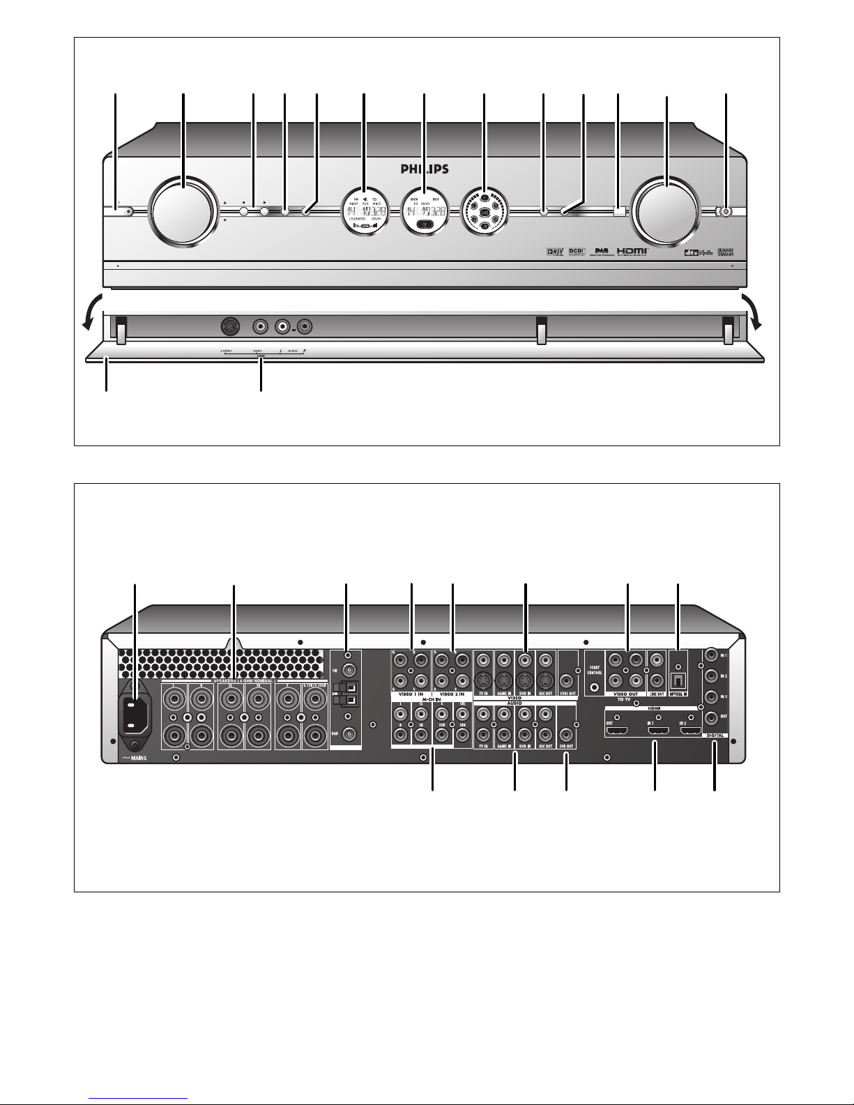
Front view
Rear view

4 ENGLISH
Index
1. Important information ..........................................................................................6
2. Introduction.........................................................................................................7-8
Packaging contents..............................................................................................................................................................8
3. Functional overview..........................................................................................9-13
3.1 Front view .......................................................................................................................................................................9
3.2 Rear view...............................................................................................................................................................10-11
3.3 Remote control..................................................................................................................................................11-12
3.4 Displays ..........................................................................................................................................................................13
4. Installation .......................................................................................................14-23
4.1 General remarks .......................................................................................................................................................14
4.2 Connecting to your TV..................................................................................................................................14-15
4.3 Connecting analogue audio equipment...............................................................................................15-16
4.4 Connecting digital audio equipment.............................................................................................................16
4.5 Connecting analogue multi-channel equipment.....................................................................................17
4.6 Connecting digital HDMI equipment ...........................................................................................................18
4.7 Connecting video equipment....................................................................................................................18-20
4.8 Connecting speakers.......................................................................................................................................20-21
4.9 Positioning the speakers................................................................................................................................21-22
4.10 Connecting antennas...........................................................................................................................................22
4.11 Connecting a video camera............................................................................................................................23
4.12 Connecting headphones ...................................................................................................................................23
4.13 Installing the batteries in the remote control.......................................................................................23
4.14 Connecting to the mains ..................................................................................................................................23
5. System menu ........................................................................................................24
5.1 Basic menu navigation............................................................................................................................................24
6. Setting up the receiver...................................................................................25-26
6.1 Positioning your DFR9000..................................................................................................................................25
6.2 Switching on and off...............................................................................................................................................25
6.3 Selecting your system menu language.........................................................................................................25
6.4 Setting the speaker size and distance...................................................................................................25-26
6.5 Setting the speaker volume................................................................................................................................26
6.6 Reassigning input sockets.....................................................................................................................................26
7. Operating the amplifier..................................................................................27-28
7.1 Source selection........................................................................................................................................................27
7.2 Sound control.............................................................................................................................................................27
7.3 Selecting surround modes ..................................................................................................................................27
7.4 Playing sources...........................................................................................................................................................28
7.5 Recording from sorces..........................................................................................................................................28
7.6 Recording from the digital input .....................................................................................................................28
8. Operating the tuner........................................................................................29-31
8.1 Tuning to radio stations (FM, FM-M and MW band)......................................................................... 29
8.2 Preset radio stations (FM, FM-M and MW band)........................................................................ 29-30
8.3 DAB radio stations...........................................................................................................................................30-31
9. Surround modes...................................................................................................32

ENGLISH 5
10. System menu overview ..................................................................................33-39
10.1 Configuration menu......................................................................................................................................33-34
10.2 Balance menu...........................................................................................................................................................34
10.3 Speakers menu................................................................................................................................................34-35
10.4 Tuner menu ...............................................................................................................................................................35
10.5 Picture menu............................................................................................................................................................36
10.6 Enhancement menu......................................................................................................................................36-37
10.7 A/V input menu...............................................................................................................................................37-38
10.8 Gain menu.................................................................................................................................................................39
11. Troubleshooting...............................................................................................40-42
12. Glossary............................................................................................................43-45
13. Technical specifications...................................................................................46-47
Helpline ........................................................................................................................49
Warranty ......................................................................................................................50

6 ENGLISH
1. Important information
• Please install and connect the product in the order described in this manual only.
This assures best installation results with the least technical hassles.
• Please read this guide carefully before using your DFR9000 and keep it for future
reference.
• During set-up and installation, it may be helpful to have the instructions for your audio
system,TV or other components at hand.
Safety Precautions
• NEVER MAKE OR CHANGE CONNECTIONS WITH THE POWER OF YOUR AUDIO
SYSTEM SWITCHED ON OR YOUR DFR9000 CONNECTED TO THE MAINS.
• Before operating the set, check that the operating voltage indicated on the type plate on
the bottom of your set is identical with the voltage of your local mains supply. If not, please
consult your dealer.
• The set should not be exposed to dripping or splashing.
No object filled with liquids, such as vases, should be placed on the product.
• Do not expose the set to excessive moisture, rain, sand or heat sources caused by heating
equipment or direct sunlight.
• Allow a sufficient amount of free space all around your DFR9000 for adequate ventilation.
• Do not open the set. Contact your Philips retailer if you experience technical difficulties.
• Place the set on a flat, hard and stable surface. When the set is switched to standby mode,
it is still consuming some power. To disconnect the set from the power supply completely,
remove the AC power plug from the wall socket.
• Do not place the unit directly on a carpeted surface.
• To prevent your DFR9000 from overheating internally, make sure the air around your
DFR9000 can circulate . Also, avoid putting any heat sources (e.g. a DVD player)
underneath.
• To prevent your DFR9000 from overheating internally, never place anything on top of it.
• Do not use extension leads.To avoid safety hazards, use only the mains lead supplied with
your set.
• Do not run mains leads under rugs or carpets or place heavy objects on them.
• Damaged mains leads should be replaced immediately by a mains lead meeting factory
specifications.
• When disconnecting the mains lead from the wall socket, always pull on the plug; never pull
on the lead.
• If you do not intend to use the set for any considerable length of time, disconnect the plug
from the wall socket.
• Before moving the set, be certain to disconnect any interconnection leads with other
components, and make certain that you disconnect the set from the wall socket.
Note:To avoid overheating of the set, a safety circuit has been built in.The set will turn down the
volume or switch off sound completely if it becomes too hot. If this happens, wait until the set
has cooled down.
This set complies with the radio interference requirements
of the European Community.

ENGLISH 7
2. Introduction
DFR9000
Congratulations on your purchase of one of the most sophisticated and reliable products on
the market today.Your DFR9000 is a high-definition multimedia interface A/V receiver. Not only
is your DFR9000 an exellent audio receiver with extremely clear sound, it also provides an
HDMI interface for delivering excellent digital picture quality from source components to your
TV or monitor screen.Your DFR9000 combines FM and DAB, giving the widest of listening
options, as well as improved clarity of sound and more stations.We are sure that, used
properly, it will bring you years of enjoyment. Please read this manual carefully before using
your DFR9000 and keep it for future reference, as it is a convenient source of information
about your DFR9000.
DFR9000 features
Dolby Digital EX and DTS ES
Dolby Digital EX and DTS ES are 6.1-channel formats, with the rear surround audio channel
discretely encoded into the Dolby Digital and DTS bit-stream.The formats offer enhanced
spatialization over the surround channels for complete 360º sound localization.
HDMI Digital AV connection
HDMI stands for High Definition Multimedia Interface. It is a direct connection that can carry
digital HD video as well as digital multi-channel audio. By eliminating the conversion to
analogue signals it delivers perfect picture and sound quality.
Digital Audio Broadcasting
Digital Audio Broadcasting (DAB) is the latest in digital radio technology.
It allows you to enjoy your favorite radio stations in crystal clear, near CD-quality sound.
What’s more, you get an even wider choice of radio stations.
NSV™ Precision Video
NSV™ Precision Video is an embedded noise reduction technology that eliminates existing
noise inherent in video signals, thereby providing a more refined picture viewing experience.
Video Upscaling
With Video Upscaling you can increase the resolution of SD (Standard Definition) video signals
that DVD uses to HD (High Definition) so you will be able to see more details thanks to a
sharper, more true-to-life picture.
UCD Digital Amplifier
The UCD Audiphile Digital Amplifier is a full digital Class D amplifier designed to give the
lowest output impedance and the best audio performance and efficiency.
Trademark acknowledgment
HDMI, the HDMI logo and High-Defenition-Multimedia Interface are trademarks or registered trademarks of HDMI
licening LLC.
Noise Shaped Video is a trademark of Analog Devices Inc.
8 ENGLISH
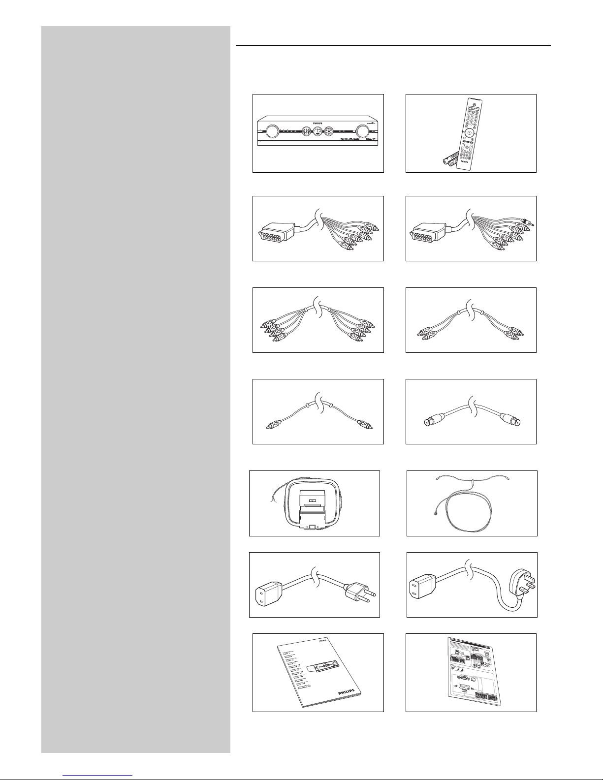
Packaging contents
Please check whether the following items are present in the box of the Digital Surround
Receiver.They are provided to help you set up and use your DFR9000.
DFR9000 Remote control (including batteries)
6-cinch to Scart cable 6-cinch + Scart control to Scart cable
4-cinch audio cable (2x) 2-cinch audio cable
Digital cinch (coaxial) cable FM antenna cable
AM antenna DAB antenna
OR
Mains lead Europe Mains lead U.K.
Instructions for Use Quick Install Guide
S
TAN
D
B
Y
-
O
N
S
O
U
R
C
E
O
K
SY
S
T
EM
M
EN
U
+
+
SU
R
R
OU
N
D
BA
SS
/TREB
L
E
IR
PH
O
N
ES
V
O
L
U
M
E
P
U
L
L
T
O
O
P
E
N
P
U
L
L
T
O
O
P
E
N
+
+
+
STANDBY-ON
SOURCE
OK SYSTEM MENU
++
SURROUND BASS/TREBLE IR PHONES
VOLUME
PULL TO OPENPULL TO OPEN
++ +
DFR 9000 DIGITAL SURROUND RECEIVER

ENGLISH 9
3. Functional overview
3.1 Front view
1 B STANDBY-ON
Switches the DFR9000 on and to standby.
Standby/On indicator (indicator in the Power/standby button)
– Lights up red when your DFR9000 is connected to the mains and when it is switched
off (to Standby).
– Goes out when your DFR9000 is switched on.
2 SOURCE
Selects the various connected sources in amplifier mode.
34
– Navigates in up (3) and down (4) direction in the menu.
– Select previous (4) and next (3) radio stations in TUNER or DAB mode.
3 12
– Navigates in left (1) and right (2) direction in the menu.
– Selects next (2) or previous (1) preset station in TUNER and DAB mode.
4 OK
– Confirms actions in the menu.
– Selects secondary audio services in DAB mode.
5 SYSTEM MENU
Opens and closes the system menu.
6 Left display
– Indicates the present status of the DFR9000.
– Indicates signal strength in DAB mode.
– Indicates the present source.
7 Centre display
Informs you on the present status of your DFR9000, selected surround modes and
displays the system menu, submenus and menu settings.
8 Right display
– Shows which speakers are active.
– Indicates volume level.
9 SURROUND
Selects the various available surround modes. Availability of surround modes depends on
speaker setup and type of input signal.
10 BASS / TREBLE
Enables the VOLUME control to adjust the low (Bass) and high (Treble) frequency
response for all channels.
11 IR
Receives the signals from the remote control.
12 VOLUME
Controls the output level of all audio channels.
13 PHONES
Outputs audio signals when listening with headphones.
14 Flap
Covers the audio and video input sockets on the front of the DFR9000.
15 CAM
Inputs audio and video signals from a portable external source, e.g. a video camera.
Legend of illustrations on inside flap.

10 ENGLISH
3.2 Rear view
Note: Most of the input connectors at the rear of your DFR9000 are assigned for connecting to a
specific audio/video playback/recording device.These connectors can be reassigned in the
system menu. For this see ‘6.7 Reassigning input sockets’ and ‘10.7 A/V input menu’.
16 MAINS
Mains inlet socket.
17 SPEAKERS (4 OHM NOMINAL)
Speaker connection panel for connecting:
L/R - Left (L) and right (R) front speakers;
SL/SR - Surround left (SL) and surround right (SR) speakers;
C - Centre speaker.
6.1SB/5.1SUB - Surround back speaker.To be connected in a 6.1 speaker configuration.
If no surround back speaker is connected (5.1 or less speaker configuration), these sockets
can be used for connecting a passive subwoofer.
18 ANTENNA
FM-, AM- and DAB antenna connectors.
19 VIDEO 1 IN (R, G, B, S)
RGBS video input sockets for connection to the SCART connector of a DVD player/
recorder using the 6-cinch to Scart cable supplied.
These sockets can be reassigned for connection to other video equipment.
20 VIDEO 2 IN (R, G, B, S)
RGBS video input sockets for connection to the SCART connector of a satellite receiver,
using the 6-cinch to Scart cable supplied.
These sockets can be reassigned for connection to other video equipment.
21 VIDEO
TV IN / GAME IN / DVD IN
CVBS (upper row) and S-Video (lower row) video input sockets for connecting to the
CVBS or S-Video output sockets of a TV, game console or DVD player/recorder.
These sockets can be reassigned for connection to other video equipment.
REC OUT
CVBS (upper socket) and S-Video (lower socket) video output sockets for connecting to
the CVBS or S-Video input sockets of a DVD recorder or VCR.
CVBS OUT
CVBS output socket for connection to a TV with a CVBS input socket.
22 TO TV
These output sockets are used for connecting your DFR9000 to the Scart connector of
your TV, using the 6-cinch + Scart control to Scart cable.
SCART CONTROL
For inserting the 2.5mm jack.When your DFR9000 is activated, Scart control will
automatically switch your TV to the correct (active) input source (provided that a
Scart connection has been made).The active source will be shown on the TV screen.
VIDEO OUT
RGBS output sockets for inserting the four video cinch connectors.
These sockets can also be connected to the RGB input sockets of a TV.
LINE OUT
Audio output sockets for inserting the two audio cinch connectors.
23 OPTICAL IN
Audio input socket for connection to the digital (optical) audio output socket of a satellite
receiver.This socket can be reassigned for connection to other digital equipment
(e.g. a CD player, DVD player or CD recorder).
24 M-CH IN
Audio input sockets for connection to the multichannel audio output sockets of
multichannel equipment.These sockets are assigned for connection to a SACD player.
If no multichannel equipment is available the L/R, SL/SR and C/SUB sockets can be
reassigned for connection to analog audio equipment (CD IN, CD-R IN and AUX IN).
The SBL/SBR sockets has no function when no multichannel equipment is connected.
ENGLISH 11
25 AUDIO - TV IN / GAME IN / DVD IN
Stereo audio input sockets for connection to the audio output sockets of a TV, game
console or DVD player. If one of these sockets is connected to a recording device, this
socket needs to be selected in the 'Configuration' menu (submenu 'Rec audio').
AUDIO - REC OUT
Stereo audio output sockets for connecting to the audio input sockets of a DVD recorder
or VCR.
26 SUB OUT
Output socket for connecting to an active subwoofer.
27 HDMI - OUT
Output socket for connection to a TV with an HDMI input socket.
HDMI - IN 1
Input sockets for connection to the output socket of a SACD player.
HDMI - IN 2
Input sockets for connection to the output socket of an HDMI source device.
These sockets can be reassigned for connection to other HDMI equipment (e.g. an HDMI
DVD player or a satellite receiver).
28 DIGITAL IN 1 / IN 2 / IN 3
Audio input sockets for connection to the digital (coaxial) output socket of digital
playback/recording equipment.
IN 1: DVD player/recorder
IN 2: CD player/recorder
IN 3: Any digital (coaxial) device.
These sockets can be reassigned for connection to other digital playback/recording
equipment (e.g. a CD player/recorder, DVD player/recorder).
DIGITAL OUT
Output socket for connection to the digital input socket of a CD recorder.
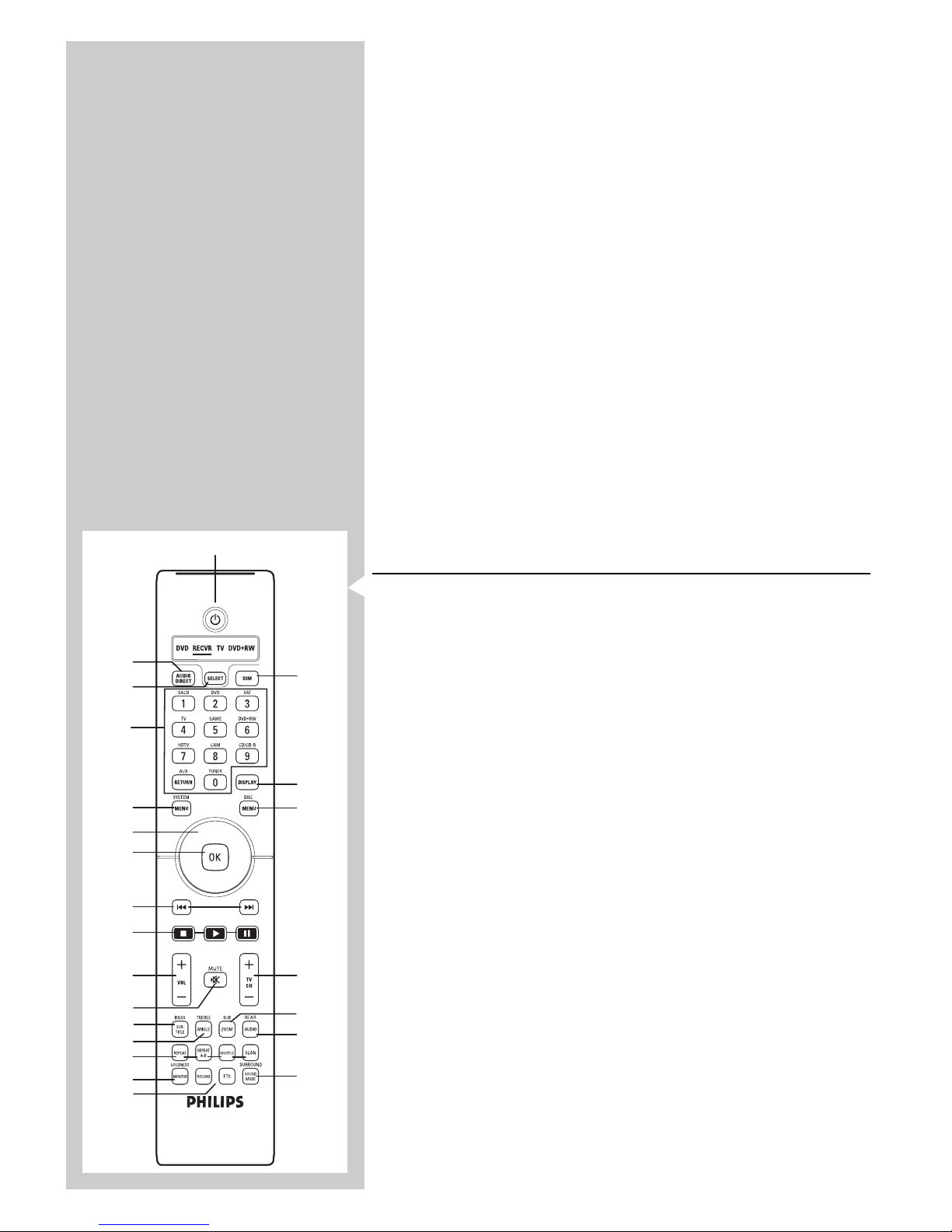
3.3 Remote control
Notes
– This remote control is a Philips system remote control which is capable of controlling other
Philips equipment as well.Your DFR9000 however does not operate all functions of other
equipment. If you wish to operate specific functions of other Philips equipment, please refer to
the Instructions for Use, supplied with the respective equipment.
–Your DFR9000 can only be controlled via the remote control if the remote control is set to
RECVR.
– Buttons with a blue function description can only perform this function in RECVR (receiver)
mode.
1 B
Switches the DFR9000 on and to standby.
2
AUDIO DIRECT
Switches between audio delay on and off.Audio delay must first be enabled in the system
menu.
3 SELECT
Selects the device you wish to operate via the remote control. In RECVR mode, the
DFR9000 can be operated. In DVD,TV and DVD+RW mode, Philips DVD players,TVs
and DVD recorders can be operated.
Status window
Shows the selected device (underlined).
4 Source selection buttons
– In RECVR mode these buttons select the required source (only sources configured in
the A/V input menu your DFR9000. See '10.7 A/V input menu').
– When SACD is selected as source, the SACD button toggles between audio input 1
and audio input 2. See '4.5 Connecting analogue multichannel equipment' and
'4.6 Connecting digital HDMI equipment'.
– When TUNER is selected as source, the TUNER button toggles between FM,
FM-M(ono), MW and DAB broadcasting.
– When system menu sub-item 'Audio in' (in 'Configuration' menu) is set to '3 x stereo',
the CD/CDR button toggles between CD and CDR input.
Numerical keypad (0-9)
Your DFR9000 does not support this function.
3
2
4
5
6
7
8
9
0
!
@
#
$
%
^
£
™
¡
)
*
&
1
(
1
2
3
4
12 ENGLISH
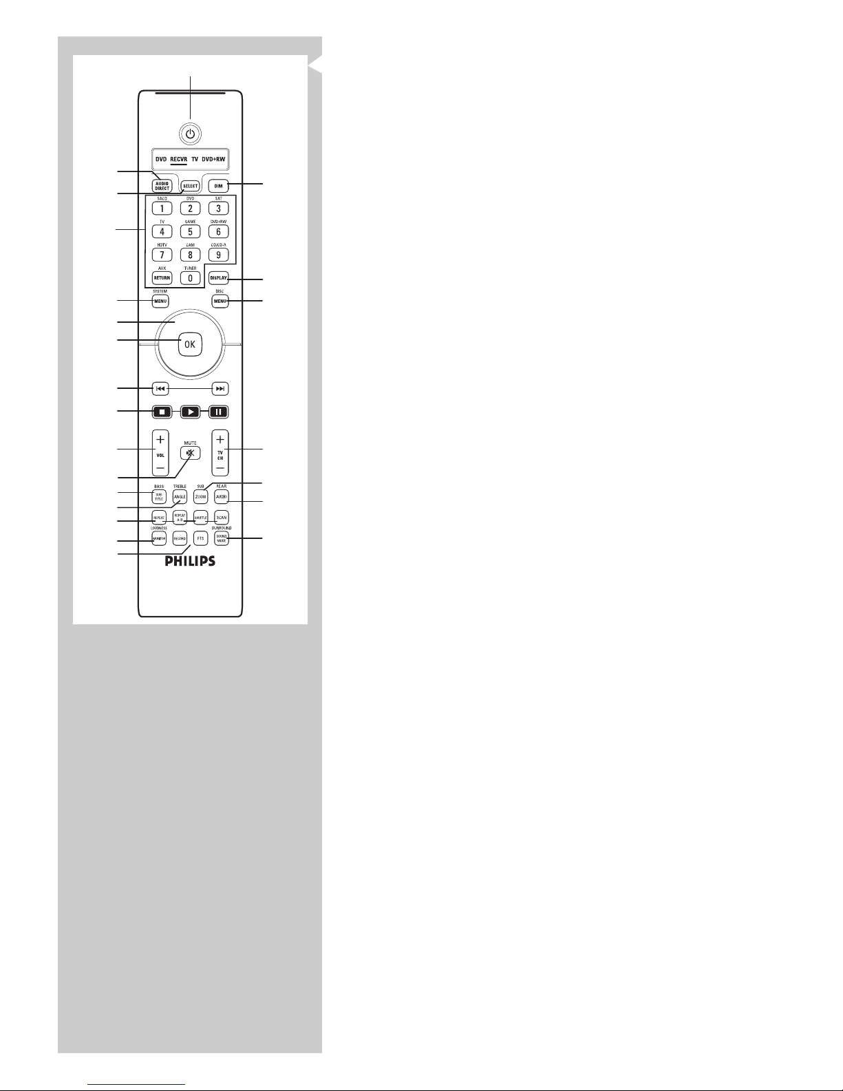
5 SYSTEM MENU
Opens and close the system menu.
6 3, 4, 1 and 2
– Navigates in up (3), down (4), left (1) and right (2) direction in the system menu.
– Selects next (4, 2) or previous (3, 1) preset station in Tuner and DAB mode.
7 OK
– Confirms actions in the menu.
– Selects secondary audio services in DAB mode.
8 ∞§
Search previous/next frequency in TUNER mode.
Select previous/next broadcasting frequency in DAB mode.
9 9 (STOP) / B (PLAY) / ; (PAUSE)
In system menu mode, the 9 (STOP) closes the menu without storing any settings.
The other functions are not supported by your DFR9000.
10 – VOL +
Adjusts the volume up (+) and down (–).
11 c MUTE
Mutes speaker and headphones output.
12 BASS / SUBTITLE
Enables the – VOL + button to adjust the low frequency response.
13 TREBLE / ANGLE
Enables the – VOL + button to adjust the high frequency response.
14 REPEAT / REPEAT (A-B) / SHUFFLE /SCAN
These buttons have no function.
15 LOUDNESS / MONITOR
Switches loudness on and off.
16 RECORD / FTS
This button has no function.
17 SURROUND / SOUND MODE
Selects the various available surround modes.What surround modes are available is
dependent on the number of speakers connected and the type of input signal
(stereo or multichannel).
18
REAR / AUDIO
Enables the – VOL + button to adjust the volume of the surround rear speaker.
19 SUB / ZOOM
Enables the – VOL + button to adjust the volume of the subwoofer.
20 – TV CH +
Selects TV channels up (+) and down (–).
21 DISC MENU
These buttons have no function.
22 DISPLAY
In tuner mode:Toggles between RDS name and frequency on left display.
In DAB mode:Toggles between station name, programme type, ensemble, signal strength
information on left and middle display.
In other (A/V) modes:Toggles between surround mode information, video input
information, audio input information and type of incoming signal
(video- and audio stream information).
Information is shown on left and middle display.
23 DIM
Decreases/increases display brightness.
3
2
4
5
6
7
8
9
0
!
@
#
$
%
^
£
™
¡
)
*
&
1
(
1
2
3
4
ENGLISH 13
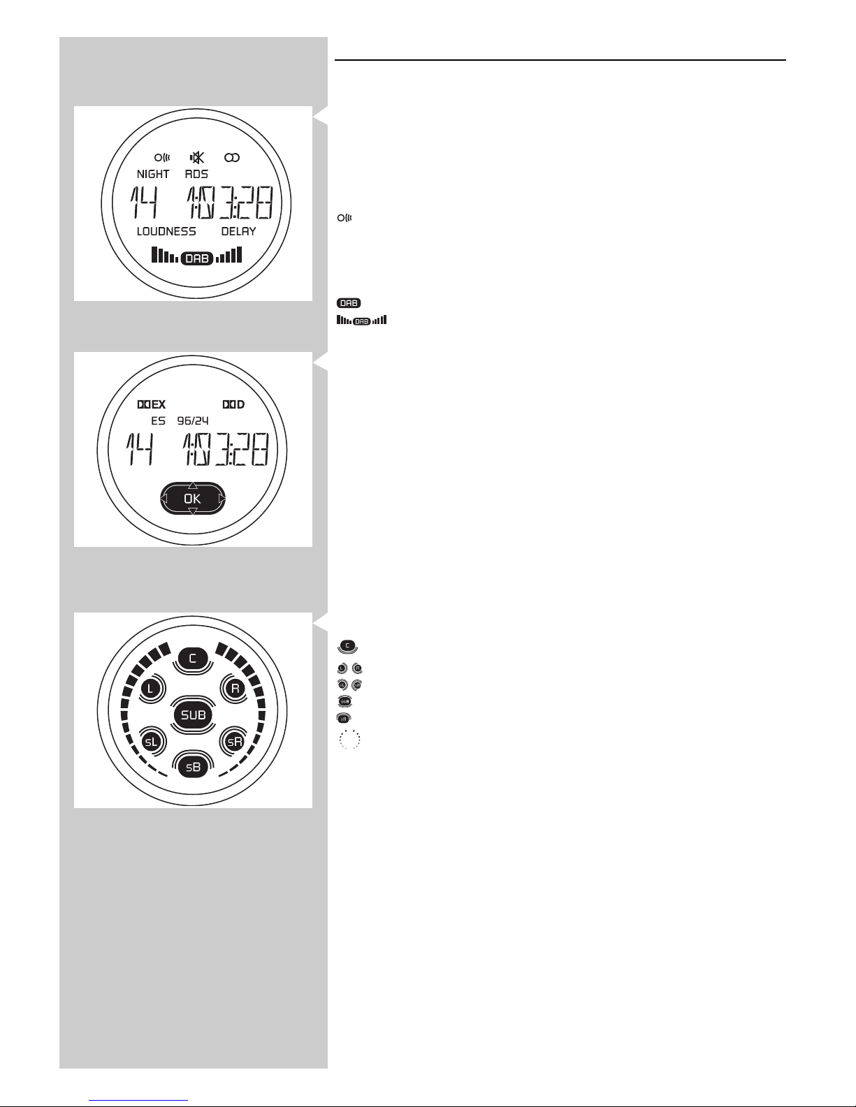
3.4 Displays
Left display
This display informs you on the current status of the active source.
88888888
This section of the display indicates the selected source, selected waveband, preset radio station
number, tuner frequency, audio/video selection and shows feedback of the receiver during
operation.
c - Sound of active source muted.
- Signal from remote control received.
i - Radio station received in stereo.
NIGHT - Night mode selected.
RDS - RDS radio station is being received.
DELAY - Audio delay activated.
LOUDNESS - Loudness activated.
- DAB broadcasting activated. Flashes if secondary audio services are available.
- Indicate reception quality level.
Centre display
This display informs you on the the type of incoming audio signal, selected surround modes and
displays the system menu, submenus and menu settings.
For an explanation of surround modes see '9. Surround modes'.
For an overview and expanation of menu items see '10. System menu overview'.
Input signal indications:
dEX - Dolby Digital EX available.
dD - Dolby Digital available.
DTS ES - DTS ES available.
DTS 96/24 - DTS 96/24 available.
88888888
This section of the display is used for feedback of the receiver, selected wavebands, preset radio
station numbers, tuner frequencies, selected sources, selected surround modes, audio/video
indication, values, menu information and scrolling text.
Right display
This display informs you of the current channel output.
- Centre speaker channel active.
- Left and right speaker channels active.
- Surround left and right speaker channels active.
- Subwoofer channel active.
-
Surround back channel active.
- Volume level indication.
14 ENGLISH
4. Installation
4.1 General remarks
– Most input sockets of your DFR9000 are assigned for connection to a specific device.
In the next chapters we will therefore only describe how to connect these specific devices
to your DFR9000. If you wish to connect other devices, you first reassign the sockets for
connection to these devices.This can be done in the system menu.
For this see '6.7 Reassigning input sockets' and '10.7 A/V Input menu'.
Connections can then be made as described below. Please refer to the chapter
'Functional overview' for an overview of connectors and the devices they are assigned to.
– The numbers between brackets refer to the numbers in the illustrations on page 3.
– The arrows in the illustrations indicate the direction of the signal.
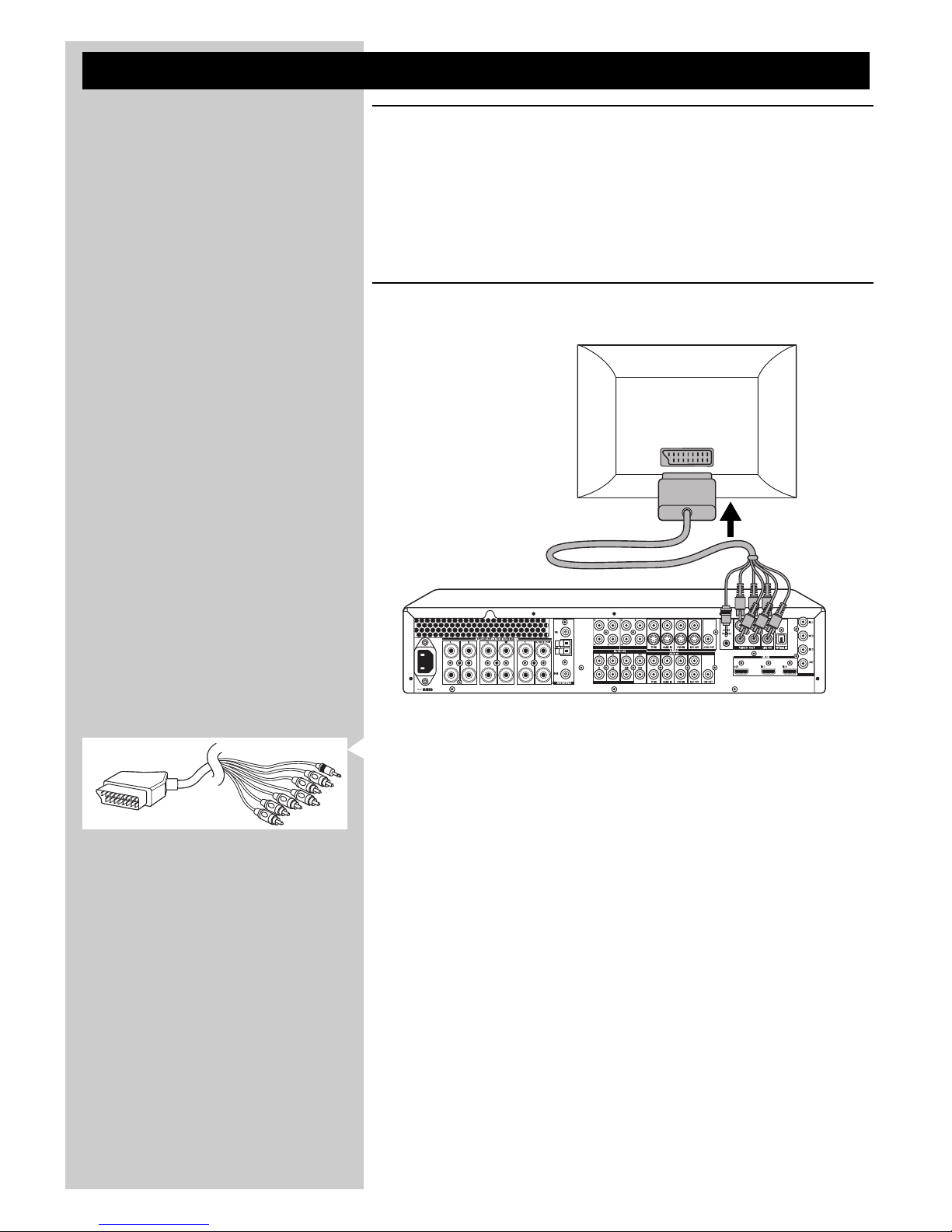
4.2 Connecting to your TV
SCART/RGBS connection
• Make sure the receiver is switched off and unplugged from the wall outlet before making
any connections.
• Connect the Scart control (2.5 mm jack) of the 6-cinch + Scart control to Scart cable
supplied to the SCART CONTROL connector (22) of your DFR9000.
> When your DFR9000 is reactivated after being switched off, Scart control switches your
Scart-enabled TV to the correct input source immediately.
• Connect the red, green, blue and yellow plugs of the cable to the corresponding VIDEO
OUT connectors (22) of your DFR9000.
• Connect the red and white audio plugs of the cable to the corresponding LINE OUT
connectors (22) of your DFR9000.
• Connect the Scart connector at the other end of the cable to the Scart input connector
of your TV.
CD IN CD-R IN AUX IN
SCART INPUT
TV
ENGLISH 15
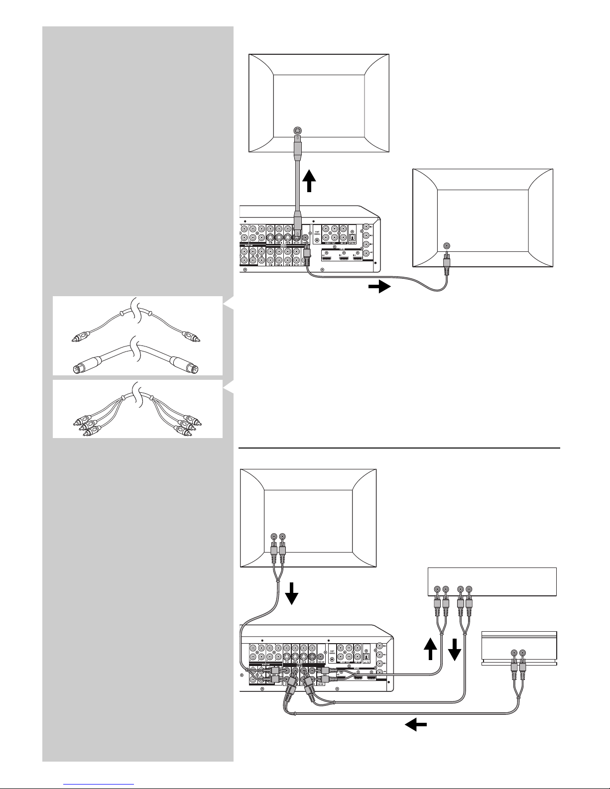
S-Video / CVBS connection
• If your TV is equipped with an S-Video input socket you can connect this socket to the
REC OUT output socket (21 - lower row) of your DFR9000. For this, use an optional S-
Video connection cable.
• If your TV is equipped with a CVBS input socket you can connect this socket to the
CVBS output socket (21) of your DFR9000. For this use an optional 1-cinch connection
cable.
Notes:
– If your TV is equipped with progressive scan component video, connect an optional 3-cinch
connection cable to the RGB sockets (22) of your DFR9000.
– For connection to a TV with an HDMI input socket see ‘Connecting HDMI equipment’.
4.3 Connecting analogue stereo audio equipment
For connection to analogue audio equipment, six input sockets (AUDIO:TV IN, GAME IN and
DVD IN - 25) and two output sockets (REC OUT 25) are available.
CD IN CD-R IN AUX IN
AUDIO OUT
AUDIO IN AUDIO OUT
AUDIO OUT
TV
DVD recorder
Game console
CD-R IN AUX IN
CVBS IN
S-VIDEO IN
TV
TV
 Loading...