

Page 1
Car Entertainment System
CEM250/55/98/51
CEM250X/78
TABLE OF CONTENTS
Page
PCBs Location ......................................................................1-1
Speci cations .......................................................................1-2
Measurement Setup .............................................................1-3
Service Aids, Safety Instruction, etc .....................................1-4
Instructures on CD Playability ....................................1-5 to 1-6
Disassembly Diagrams ...............................................2-1 to 2-2
Software Version Check & Upgrade .....................................3-1
Malfunction Check Chart ......................................................3-2
Set Block Diagram ................................................................4-1
Set Wiring Diagram ..............................................................5-1
Main Board ..............................................................................6
Servo Board.............................................................................7
CB/FB/USB Board ................................................................... 8
SD Board ................................................................................. 9
Key Board ..............................................................................10
Set Mechanical Exploded View & Parts List .......................... 11
Revision List .......................................................................... 12
©
Copyright 2009 Philips Consumer Electronics B.V. Eindhoven, The Netherlands
All rights reserved. No part of this publication may be reproduced, stored in a retrieval system or
transmitted, in any form or by any means, electronic, mechanical, photocopying, or otherwise without
the prior permission of Philips.
Published by JZ-SL 0950 Service Audio Printed in The Netherlands Subject to modification
Version 1.4
CLASS 1
LASER PRODUCT
© 3141 785 33194
Page 2

Location of PCBS
1-1
SD BOARD
VERSION VARIATIONS:
Board inused:
SD BOARD
FB BOARD
KB BOARD
CB BOARD
MAIN BOARD
SERVO BOA RD
Features
FB BOARD
MAIN BOARD
Type/Versions
Service policy
Type/Versions
Feature diffr ence
CB BOARD
/78 /98
/55
C C C
C C C
C C C
C C C
C/M C/M C/M
C/M C/M C/M
/78 /98
/55
KB BOARD
SERVO BOA RD
CEM250
CEM250
* TIPS:C--Com po ne nt Lever Repair.
M--Module Lever R ep ai r
--Used
Page 3

SPECIFICATIONS
1-2
General
Power supply:
Fuse:
Suitable speake r im pe dance:
Maximum power out pu t:
Continuous powe r ou tp ut:
Pre-Amp outpu t vo lt age:
Subwoofer outpu t vo lt age:
Aux-in level:
Dimensions(W×H×D) :
Wight:
Radio
Frequency range
-FM
Frequency range
-AM(MW)
Usable sensitiv it y
-FM
Usable sensitiv it y
-AM(MW)(S/N =2 0d B)
Frequency respo ns e
Stereo separati on
Signal/noise ra ti o
12V DC(11V- 16 -) ,
negative ground
15V
4-8Ω
45W×4channels
22W×4channels(4Ω1 0%
T. H.D )
2. 0V(USB p la y mo de;
1kHz,0dB ,10kΩ load)
2. 0V(USB p la y mo de;
61kHz, 0d B, 10kΩ load)
≥300mV
188×58×128MM
1. 0kg
87.5-108 .0MHz(Eur)
87.5-107 .9MHz(Ame)
522-1620kHz(E ur )
530-1710MHz(A me )
8dBu
3. 2dBu
20Hz-20kHz
30db(1kHz)
>75dB
Components
Car audio system
Remote contro l
Microphone
Microphone hold
Rubber cushion
Disassembly too l
Front panel
Carrying case f or f ro nt panel
Tri m pl ate
Screw
User manual
Quick start gui de
Standard connec to r
1
1
1
1
1
2
1
1
2
4
1
1
1
Note: Specifications and design are subject to change
without notice for product improvements.
Page 4

MEASUREMENT SETUP
Tuner FM
1-3
Bandp as s
25 0Hz -1 5kH z
e.g . 7122 70 7 48001
LF Voltm et er
e.g . PM253 4
RF Gene ra tor
e.g . PM532 6
DUT
Ri=50Ω
S/N and d is torti on mete r
e.g . Sound Tec hnolo gy ST17 00B
Use a ban dp ass fil ter to el imina te h um(50 Hz,10 0H z) and di sturb ance fr om t he pilo ttone (1 9kHz, 38kHz ).
Tuner AM (MW,LW)
RF Gene ra tor
e.g . PM532 6
Ri=50Ω
DUT
Frame a er ial
e.g . 7122 70 7 89001
Bandp as s
25 0Hz -1 5kH z
e.g . 7122 70 7 48001
LF Voltm et er
e.g . PM253 4
S/N and d is torti on mete r
e.g . Sound Tec hnolo gy ST17 00B
To avoid at mo spher ic inte rfere nc e all AM-m easur em ents ha ve to be ca rr ied out i n a Farad ay s c age.
Use a ban dp ass fil ter ( or at l east a hi gh p ass fil ter wit h 250Hz ) to e limin ate hum ( 5 0H z,100 Hz ).
CD
Use Audi o Si gnal Di sc SBC4 29 4 822 397 3 0184
(repl ac es test d isc 3)
DUT
L
Cassette
Use Uni ve rsal Test Cass et te CrO2 S BC419 4 822 397 3 00 69
or Univ er sal Test Cas sette F e SB C420 48 22 397 30 071
LF Gene ra tor
e.g . PM5110
DUT
R
S/N and d is torti on mete r
e.g . Sound Tec hnolo gy ST17 00B
LEVEL METE R
e.g . Sennh eiser U PM550
wit h FF-fi lter
'
L
R
S/N and d is torti on mete r
e.g . Sound Tec hnolo gy ST17 00B
LEVEL METE R
e.g . Sennh eiser U PM550
wit h FF-fi lter
Page 5
SERVICE AIDS
1-4
GB
All ICs and many other semi-conductors are
susceptible to electrostatic discharges (ESD).
Careless handling during repair can reduce life
drastically.
When repairing, make sure that you are
connected with the same potential as the mass
of the set via a wrist wrap with resistance.
Keep components and tools also at this
potential.
WARNING
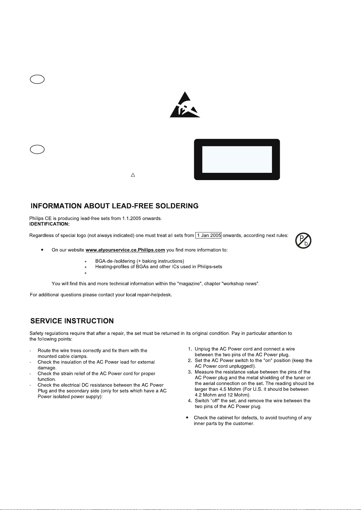
GB
Safety regulations require that the set be restored to its original
condition and that parts which are identical with those specified,
be used
Safety components are marked by the symbol
!
.
ESD
CLASS 1
LASER PRODUCT
Lead free
Page 6
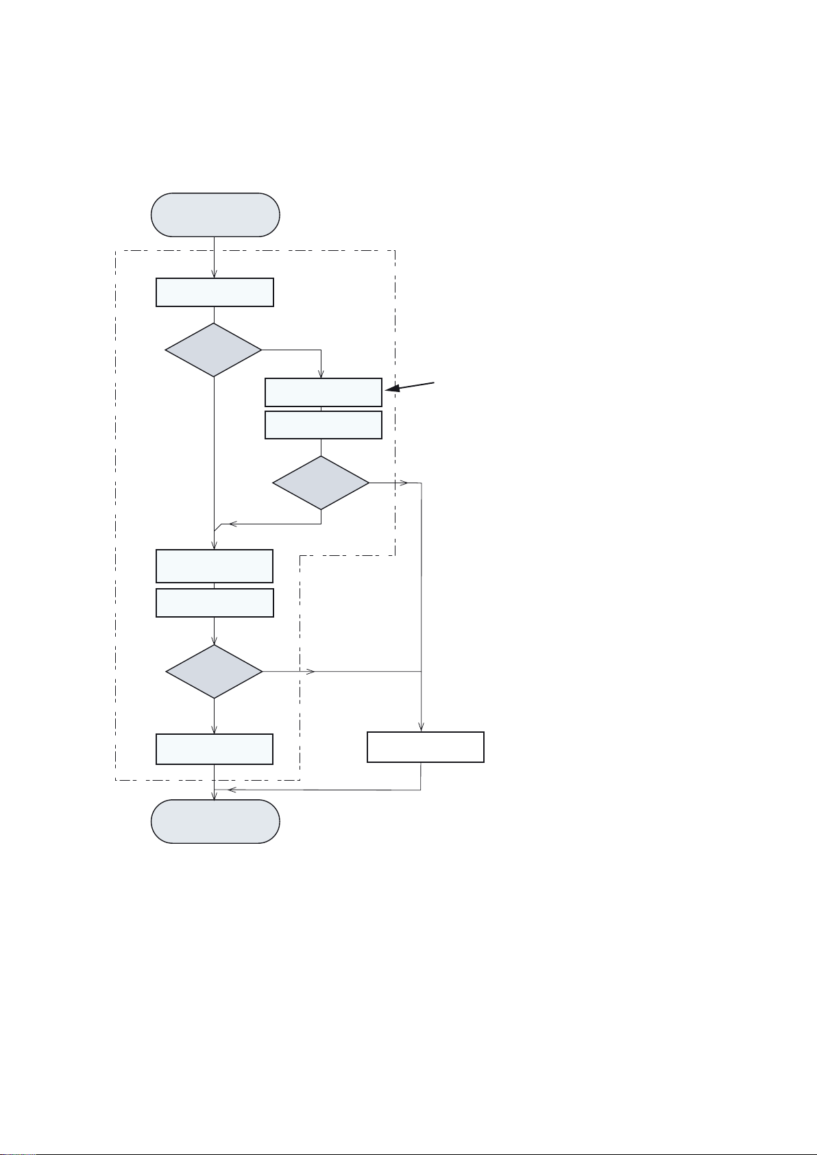
INSTRUCTIONS ON CD PLAYABILITY
Customer comp la in t
"CD relate d pr ob lem"
Set remains closed!
Check playabili ty
①
1-5
playability
ok?
Y
Play a CD
for at le ast 10 mi nutes
check playability
playability
ok?
Y
N
"fast" lens cleaning
check playability
playability
ok?
Y
N
③
N
For flap loaders( =a ccess to CD drive pos si bl e)
clesning method④i s re co mmended
ann lnf o fo r custo mer
"SET O K"
return set
①-④For descripti on -s ee following pages
②
Exchange CDM
Page 7

INSTRUCTIONS ON CD PLAYABILITY
Customer comp la in t
"CD relate d pr ob lem"
Set remains closed!
Check playabili ty
①
1-5
playability
ok?
Y
Play a CD
for at le ast 10 mi nutes
check playability
playability
ok?
Y
N
"fast" lens cleaning
check playability
playability
ok?
Y
N
③
N
For flap loaders( =a ccess to CD drive pos si bl e)
clesning method④i s re co mmended
ann lnf o fo r custo mer
"SET O K"
return set
①-④For descripti on -s ee following pages
②
Exchange CDM
Page 8

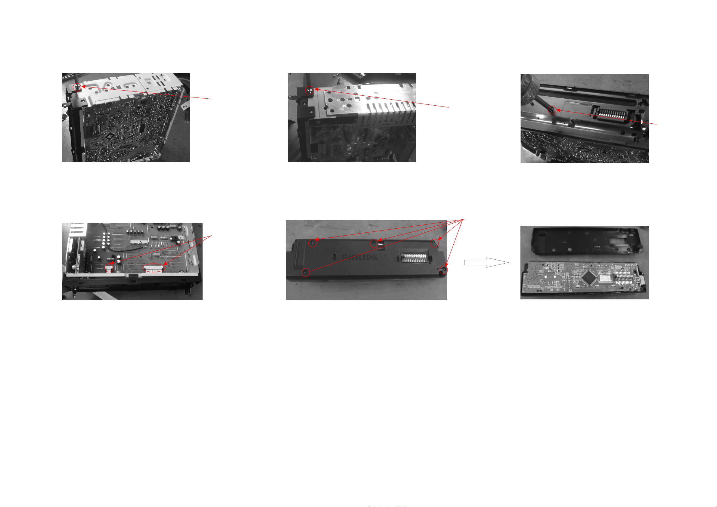
Disassembly Diagram
2-1 2-1
1
2
1. Remove the mounti ng sleeve with the removal keys.
Press key and remove t he front panel.
4. Remove the screw 3 as s hown.
2. Remove the two scre ws on the back side of
3. Remove the upper co ver with a tool.
the unit with a screw dr iver.
3
4
5. Remove the bottom c over with a tool.
6. Remove the screws 4 w ith a screw driver.
7. Remove the screw 5 wi th a screw driver.
5
8. Remove the connec tors 6, and then remove
6
7
9. Remove the adhesi ve tapes 7.
the mechanism core .
Page 9
Disassembly Diagram
10. Remove the screw 8 . 11. Remove the scr ew 9 . 12. Remove the screw 1 0 .
2-2 2-2
8
9
10
13. Remove the conne ctors 11, and then remove
the bracket with a too l.
12
11
14. Remove the screw s 12.
Page 10

3-1 3-1
Software version check & upgrade Upgrade software
1、Check Servo software version
In USB/SD/Disc mod e, press DISP + 6 simutalious ly
for 2 sec, LCD display i s as below:
VS-104
102 is the servo softw are version
2、Check MCU software version
In tuner mode, press D ISP + 6 simutaliously for 2 sec ,
LCD display is as belo w:
VM-103
101 is the MCU softwar e version
3、Check BT software version
In tuner mode, press D ISP + 5 simutaliously for 2 sec ,
LCD display is as belo w:
1、 C opy servo software "BOOT.AL I" and "nemo.bin" into USB m emory,
plug th e USB memory into USB socket.D evice u pgrade servo s oftwa re
automatically, Don't power off or disconne ct power during the upgrade,
LCD show:
SERVO UPGRADING,,,DON'T PWR OFF
Around 1 minute, servo soft ware upgrade completed and dev ice change
to radio mode automa tically
2、 Del ete the servo software in th e USB and copy the MCU so ftware
"CEM250MCU" (for C EM250) into USB memory, plug the USB memory
into USB so cket. D evice upgra de MB software software automatically
Don't powe r off or disc onnect p ower during the upgrade, LCD sho w:
MCU UPG
VBT-177
177 is the MCU softwar e version
Around 1 minute, MB software upgrade completed and device p ower
off automatic ally, d iscon nect the USB memory.
Page 11

Malfunction check chart
3-2 3-2
CD no
sound
Check power wirt,
speaker wire is
fasten or not
Powe
Fix the wire
TDA73 86 o f AMP
Chang e th e r
compo ne nts
Check C D ou tput
Check tuner circu it
and is conjoin part
is good or bad
Components
Chang e th e tuner
Check C D co ntrol
circu it i s good or b ad
Check the related
components of CD si gn al
channel, ca bl e, socket i s
good or bad
Change componen ts
of CD circuit
CD
CD display
Check 5673 ALI
circuit and its
conjoint part
Check cd whether ra nd
disc,and i ts f un ctions
whether connect t o US B
Page 12

SET BLOCK DIAGRAM
4-1 4-1
Page 13

WIRING DIAGRAM
5-1 5-1
A1 A2 A3 A4 A5 A6 A7 A8
B1 B2 B3 B4 B5 B6 B7 B8
15 A
SUB OUT
Rear line Out R
Rear line Out L
ANTENNA
Purple
Purple/
Black
Stripe
Gray
Gray/
Black
Stripe
DO NOT connect any speaker wires
to the metal body or chassis of the
vehicle. DO NOT connect the speaker
common (-) wires to each other. Connect each speaker wire directly to each
speaker terminal. All speaker common
(-) wires must remain floating.
B
Connector
1 3 5 7
B
2 4 6 8
1 3 5 7
2 4 6 8
A
FUSE
A
White/
Black
Stripe
Brown
Yellow
White
Red
Black
Blue
Green/
Stripe
Black
Green
Ignition key+12V DC When ON/ACC
Ground Lead
Motor/Electric Antenna relay control Lead
Amplifier relay control Lead
Illumination/brown
To car battery (+) Continuous +12V DC
MIC(CEM250 only)
Right Speaker
(Rear)
Right Speaker
(Front)
Left Speaker
(Front)
Left Speaker
(Rear)
Page 14

MAIN BOARD-CIRCUIT DIAGRAM
6-1 6-1
Page 15

6-2 6-2
MAIN BOARD-PCB LAYOUT TOP/BOTTOM VIEW
Page 16

SERVO BOARD-CIRCUIT DIAGRAM
7-1 7-1
Page 17

7-2 7-2
SERVO BOARD-LAYOUT DIAGRAM TOP/BOTTOM VIEW
Page 18

CB/FB/USB BOARD-CIRCUIT DIAGRAM
8-1 8-1
Page 19

8-2
CB BOARD-PCB LAYOUT TOP/BOTTOM VIEW
8-2
Page 20

8-3
FB BOARD-PCB LAYOUT TOP/BOTTOM VIEW
8-3
Page 21

8-4
USB BOARD-PCB LAYOUT TOP/BOTTOM VIEW
8-4
Page 22

SD BOARD-CIRCUIT DIAGRAM
9-1 9-1
Page 23

9-2 9-2
SD BOARD-PCB LAYOUT TOP/BOTTOM VIEW
Page 24

KB BOARD-CIRCUIT DIAGRAM
10-1 10-1
Page 25

10-2 10-2
KB BOARD-LAYOUT DIAGRAM TOP/BOTTOM VIEW
Page 26

EXPLODED VIEW-MAIN UNIT
11-1 11-1
Page 27

11 - 2
13
996510019807
30
996510019811
DOWN BUTTON LI-GUIDE
_
112
996510019644
CMB752 SPRING 1 D0.6
141
996510020150
CE250 MAIN BOARD
MECHANICAL & ACCESSORIES PARTS LIST
1 996510019813
2 996510019812
3 996510019814
4 996510019804 1 BUTTON F 996510019729 FFC 6P 1.0mm 35mm TYPE A
5 996510019805 3 BUTTON Q 996510019829 REMOTE CONTROL
6 996510019806
7 996510019802
8 996510019803
9 996510019801 DISP BUTTON
10 996510019815 USB COVER
11 996510019837
12 996510019818 BUTTON BRACKET 1
14 996510019607 SPRING PWR D0.25
16 996510019840
18 996510019839
27 996510019838 REAR PANEL
29 996510019810
30 996510019811
31 996510019800 SKIP BUTTON
DECORAT DOWN
DECORAT UP D 996510019784 I/O CABLE 2RCA/LINE/SUB/MIC
LENS BLK PHILIPS E 996510019543 I/O CABLE 16P ACC/ILL IN/SPK
5 BUTTON 5A 996510019646 CMV100 SIDE KEY
EQ BUTTON 7A 996510019785 FFC 24P 1.0mm 32mm TYPE C
RETURN BUTTON
FRONT PANEL
OPEN BUTTON
LCD ETN
LCD BACKET
UP BUTTON LI-GUIDE
-
C
996510019783 ANT CEM250 BLUETOOTH 170MM
32 996510019819
33 996510019816
34 996510019817
35 996510019799 SOURCE BUTTON 2) For Key Board module, please order
37 996510019796 DIAL UP BUTTON 996510019836_FRONT PANEL ASSY which
38 996510019797
39 996510019798 DBB AS BUTTON 3) For Main Board & Servo Board, module level
40 996510019809 RING repair can be a service option also.
41 996510019808
101 996510019836
102 996510019786 RIM 996510020151
104 996510019780
105 996510019781
107 996510019642
109 996510019641
111 996510019782 EJECT BUTTON
113 996510019638
114 996510019639 CMB752 LOCKER
115 996510019643 CMB752 SPRING 2 D0.4
BUTTON SHADE Note: 1) Only these parts mentioned in the list are
BKT FOR SOURCE BUTTON normal service parts.
BUTTON BRACKET
contains Key Board.
DIAL DOWN BUTTON
KNOB ENCODER
FRONT PANEL ASSY 4) For CD Mechanism must be ordered with Servo
board, the combined part is with code number
CABINET
LIGHT GUIDE
CM700 GEAR
DAMPER
CMB752 HANDSPIKE
129
136
141 996510020150 CE250 MAIN BOARD
996510020151 SERVO BOARD & CD MECHANISM
996510019645 SCD550 RUBBER CAP RUBBER
Page 28

11 - 3
03
996510019820
LED103
996510019820
LED WHITE D3 20mA
D
G
R
G
R
LED314
996510019610
LED B/R
Q101
996510019572
MOSFET AO3401
)
)
)
996510019697
)
ELECTRICAL PARTS LIST - KEY BOARD
EN301
IC101
IC301
LED101
LED102
LED1
LED104
LED105
LED106
LED301
LED302
LED303
LED304
LED304
LED305
LED306
LED306
LED307 996510019610
LED308 996510019610
LED309 996510019610 LED B/R IC902 996510019792 IC L7806CV TO-220 ST
996510019674
996510019609
996510019583
996510019820
996510019820
996510019820
996510019820
996510019820
996510019610
996510019610
996510019610
996510019822 LED GREEN 19-217/GHC-YRSM/3T C901 996510019789 E.CAP 3300uF 20%
996510019822
996510019610
996510019823
996510019823
ENCODER EVEJBBF2020B H20.0 SW313 996510019697 TACT SW WT1101EW1-43F-02
IC PT6523HQ LQFP-64 PTC SW314 996510019697
PHOTO DIODE 638AF4 5V 1.1A SW315 996510019697 TACT SW WT1101EW1-43F-02
LED WHITE D3 20mA SW316 996510019697 TACT SW WT1101EW1-43F-02
LED WHITE D3 20mA
LED WHITE D3 20mA
LED WHITE D3 20mA
LED WHITE D3 20mA
LED WHITE D3 20mA
LED B/R
LED B/R BT101 996510019793 MODULE BLUETOOTH
LED B/R C209 996510019788 CAP 0.047F 5.5V
LED GREEN 19-217/GHC-YRSM/3T CON406 996510019794 FFC SOCKET 25P 1.0mm
LED B/R CON601 996510019790 SOCKET 14P 2.0mm
LED RED FC-1608SEK-624C CON801 996510019560 SOCKET 16P 3.5mm DIP 90
LED RED FC-1608SEK-624C D101 996510019561 LIGHTNING DIODE YP-701M 700V
LED B/R FUS ! 996510019549 FUSE ATC-5 15A 32V
LED B/R IC901 996510019658 IC KIA78D09 TO-252
ELECTRICAL PARTS LIST - MAIN BOAR
TACT SW WT1101EW1-43F-02
LED310 996510019610 LED B/R L101 996510019795 INDUCTOR 10uH
LED311
LED312
LED313
LED315
LED316
LED317 996510019610 LED B/R Q203 996510019572 MOSFET AO3401
LED318 996510019821 LED BLUE SBS-0604BC-T3 Q204 996510019566 TRANSISTOR KRC102(NPN)
Q301
Q302
Q303
Q304
SW301
SW302
SW303
SW304
SW305
SW306
SW307
996510019610
996510019610
996510019610
996510019610
996510019610
996510019571
996510019571
996510019569
996510019569
996510019697
996510019697
996510019697
996510019697
996510019697
996510019697
996510019697
LED B/R L201 996510019795 INDUCTOR 10uH
LED B/R L401 996510019795 INDUCTOR 10uH
LED B/R L901 996510019555 CHOKE 200uH 1A 30%
LED B/R Q201 996510019569 TRANSISTOR KTC8550
LED B/R Q202 996510019566 TRANSISTOR KRC102(NPN)
TRANSISTOR 2N3904(NPN) Q401 996510019566 TRANSISTOR KRC102(NPN)
TRANSISTOR 2N3904(NPN) Q403 996510019556 TRANSISTOR BD435 TO-126C
TRANSISTOR KTC8550 Q404 996510019570 TRANSISTOR MMBT3906LT1(PNP
TRANSISTOR KTC8550 Q405 996510019566 TRANSISTOR KRC102(NPN)
TACT SW WT1101EW1-43F-02 Q406 996510019571 TRANSISTOR 2N3904(NPN)
TACT SW WT1101EW1-43F-02 Q407 996510019671 TR KRA102S(PNP) SOT-23
TACT SW WT1101EW1-43F-02 Q408 996510019570 TRANSISTOR MMBT3906LT1(PNP
TACT SW WT1101EW1-43F-02 Q409 996510019571 TRANSISTOR 2N3904(NPN)
TACT SW WT1101EW1-43F-02 Q410 996510019570 TRANSISTOR MMBT3906LT1(PNP
TACT SW WT1101EW1-43F-02 Q411 996510019566 TRANSISTOR KRC102(NPN)
TACT SW WT1101EW1-43F-02 Q412 996510019566 TRANSISTOR KRC102(NPN)
SW308
SW309
SW310
SW311
SW312
996510019697
996510019697
996510019697
996510019697
TACT SW WT1101EW1-43F-02 Q413 996510019572 MOSFET AO3401
TACT SW WT1101EW1-43F-02 Q414 996510019566 TRANSISTOR KRC102(NPN)
TACT SW WT1101EW1-43F-02 Q421 996510019566 TRANSISTOR KRC102(NPN)
TACT SW WT1101EW1-43F-02 Q422 996510019570 TRANSISTOR MMBT3906LT1(PNP
TACT SW WT1101EW1-43F-02 Q423 996510019566 TRANSISTOR KRC102(NPN)
Page 29

11 - 4
(
)
Q603
996510019567
TRANSISTOR KRC231S(NPN)
M
996510019827
SCREW PWTS BLUE ZINC M2 4
(
)
S
D
SW102
996510019727
TACT SW TS 06V ASM
D
D
ELECTRICAL PARTS LIST - MAIN BOARD ELECTRICAL PARTS LIST - SERVO BOARD
Q425 996510019571 TRANSISTOR 2N3904(NPN) EC6 996510019709 TAN.CAP 10uF 10V 20% A
Q426 996510019791 TR S8050(NPN) TO-92 K 996510019825 FFC 12P 1.00mm 160mm B TYPE
Q501 996510019571 TRANSISTOR 2N3904(NPN) L 996510019826 FFC 25P 1.0mm 120mm TYPE A
Q601 996510019567 TRANSISTOR KRC231S(NPN) LED1 996510019723 INFRARED TRANSMITTER
Q602 996510019567 TRANSISTOR KRC231S(NPN) LED2 996510019723 INFRARED TRANSMITTER
Q603 996510019567 TRANSISTOR KRC231S
Q604 996510019567 TRANSISTOR KRC231S(NPN) N 996510019564 V-RES EZJZ1V800AA 3pF DC18V
Q701 996510019570 TRANSISTOR MMBT3906LT1(PNP) Q1 996510019571 TRANSISTOR 2N3904(NPN)
Q703 996510019567 TRANSISTOR KRC231S(NPN) Q2 996510019569 TRANSISTOR KTC8550
Q805 996510019571 TRANSISTOR 2N3904(NPN) Q3 996510019571 TRANSISTOR 2N3904(NPN)
Q901 996510019572 MOSFET AO3401 Q5
Q902 996510019566 TRANSISTOR KRC102(NPN)
Q904 996510019569 TRANSISTOR KTC8550
Q905 996510019571 TRANSISTOR 2N3904(NPN)
Q906 996510019570 TRANSISTOR MMBT3906LT1(PNP)
Q907 996510019569
Q908 996510019566 TRANSISTOR KRC102(NPN) U2 996510019717 IC AM5766FM MOTOR DRIVER
Q980 996510019566 TRANSISTOR KRC102(NPN) U3 996510019621 IC AMS1117-3V3 SOT-223 AMS
Q981 996510019570 TRANSISTOR MMBT3906LT1(PNP) U7 996510019828 IC HY57V161610FTP-7
Q982 996510019566 TRANSISTOR KRC102(NPN)
Q983 996510019572 MOSFET AO3401 XT2 996510019618 TCXO 16.9344M 10ppm 20pF
R157 996510019551 THERMAL RES GBX050 PTC
TUN101 996510019562 TUNER FM/AM/LW/OIRT
TVS901 996510019577 TVS DIODE SMCJ33CA 1500W
996510029623 IC UPD78F0547 LQFP /55/78U401
TRANSISTOR KTC8550 U1
NPN
M 996510019827 SCREW PWTS BLUE ZINC M2*4
Q6
Q7
SD901
SWCLO
U8
996510019571
996510019571 TRANSISTOR 2N3904(NPN)
996510019571 TRANSISTOR 2N3904(NPN)
996510019625 12P 2.5MM SD/MMC SOCKET
996510019722 END-SENSE SW ESE11MH1
996510019622 IC M5673S LQFP-176PIN ALI
996510019619 IC EN25P20-100GCP 2M-BIT SOP8
TRANSISTOR 2N3904
NPN
U402 996510019553 IC KIA7027 TO-92 KEC
U403
U501 996510019656 IC TDA7419TR SO28 ST
U601 996510019573 IC NJM4558M SOP8 NJRC P 996510019823 LED RED FC-1608SEK-624C
U603 996510019573 IC NJM4558M SOP8 NJRC SW101 996510019612 TACT SW 2.0mm TS1107GS-3
U604 996510019573 IC NJM4558M SOP8 NJRC SW103 996510019725 TACT SW ESE11MV9
U801 996510019650 IC E-TDA7386 FLEXIWATT25 ST
U902 996510019557 IC LM2950-5V TO-92 HTC
XT401 996510019563 TCXO 8.000M 20ppm 32pF
XT402 996510019558 TCXO 32.768K 20ppm 12.5pF
Z202 996510019580 ESD DIODE PG05GBUSV 200W 24A
Z203 996510019580 ESD DIODE PG05GBUSV 200W 24A ELECTRICAL PARTS LIST - USB BOAR
Z204 996510019580 ESD DIODE PG05GBUSV 200W 24A
996510019621 IC AMS1117-3V3 SOT-223 AMS
ELECTRICAL PARTS LIST - FB BOAR
SW102 996510019727
AUX901
USB901 996510019688
996510019830
TACT SW TS-06V-ASM
SOCKET 3P 6.0mm EARPHONE
USB SOCKET 4P 2.5mm
ELECTRICAL PARTS LIST - SERVO BOAR
Note: 1) Only these parts mentioned in the list are
D2 996510019617 SCHTTKY DIODE RB551 0.5A 20V normal service parts.
Page 30

11 - 2B 11 - 2B
R
R
9
996510019642
CM700 GEAR
CON904
996510027853
F SOCKET 24P
LED317G
996510019821
LED BLUE SBS-0604BC-T3
R
R
R
18 996510019639
CMB752 LOCKER
D101
996510019823
LED RED FC 1608SEK 624C
Q101
996510019572
MOSFET AO3401
A
53 996510027861
OPEN BUTTON
IC301
996510019583
PHOTO DIODE 638AF4 5V 1.1A
Q301
996510019571
TRANSISTOR 2N3904(NPN)
()
77 996510020881
DBB AS BUTTON
L901
996510019555
CHOKE 200uH 1A 30%
Q406
996510019571
TRANSISTOR 2N3904(NPN)
(
)
B 996510019826
FFC 25P 1.0mm 120mm TYPE A
LED105
996510019820
LED WHITE D3 20mA
Q409
996510019571
TRANSISTOR 2N3904(NPN)
R
R
LED304R
996510019822
LED GREEN 19-217/GHC-YRSM/3T
Q425
996510019571
TRANSISTOR 2N3904(NPN)
R
)
Q
)
LED306R
996510027684
LED R 19 22/R6BHC C03/2T YUG
Q501
996510019571
TRANSISTOR 2N3904(NPN)
R
R
R
R
CN101
996510027869
SOCKET 6P
LED311G
996510019821
LED BLUE SBS-0604BC-T3
Q703
996510019567
TRANSISTOR KRC231S(NPN)
R
()
MECHANICAL & ACCESSORIES PARTS LIST (only for CEM250/98)
Loc. 12NC Description Loc. 12NC Description Loc. 12NC Description
MAIN UNIT
4 996510020872 1 BUTTON CON601 996520035475 SOCKET 14P 2.0mm LED315
5 996510020879 3 BUTTON CON801 996520035474 SOCKET 16P 3.5mm LED316G 996510019821 LED BLUE SBS-0604BC-T3
6 996510019781 LIGHT GUIDE
11 996510019641 CMU706 DAMPE
14 996510019782 EJECT BUTTON D101 996510019561 LIGHTNING DIODE YP-701M 700V Q1 996510019571 TRANSISTOR 2N3904(NPN)
17 996510019643 CMB752 SPRING 2 D0.4 D101 996510019561 LIGHTNING DIODE YP-701M 700V Q1 996510019568 TRANSISTOR S8050(NPN)
18 996510019639 CMB752 LOCKE
21 996510027661 CMB752 SPRING 1 D0.6
22 996510019638 CMB752 HANDSPIKE D2 996510019617 SCHTTKY DIODE RB551 0.5A 20V Q2 996510027868 TR S9014LT1(NPN)
25 996510027877 MAIN BOARD MI ASSM D418 996510027875 REC DIODE Q201 996510019569 TRANSISTOR KTC8550
40 996510027855 SERVO BOARD MI ASSM&CDM D901 996510027865 REC DIODE Q201 996510019569 TRANSISTOR KTC8550
47 996510019808 KNOB ENCODER EC6 996510019709 TAN.CAP 10uF 10V 20%
48 996510020863 DECORAT DOWN EN301 996510019674 ENCODER EVEJBBF2020B H20.0 Q203 996510019572 MOSFET AO3401
49 996510020869 DECORAT UP FUS 996510019549 FUSE ATC-5 15A 32V Q204 996510019566 TRANSISTOR KRC102(NPN)
50 996510019815 USB COVER IC101 996510019609 IC PT6523HQ LQFP-64 PTC Q3 996510019571 TRANSISTOR 2N3904(NPN)
65 996510024811 REAR PANEL IC901 996510020507 IC L7809CV TO-220 ST Q302 996510019571 TRANSISTOR 2N3904(NPN)
66 996510027843 KEY BOARD IC902 996510019574 IC L78M06CDT-TR TO-252 ST Q303 996510019569 TRANSISTOR KTC8550
69 996510020876 RETURN BUTTON J1 996510027849 F SOCKET 16P Q304 996510019569 TRANSISTOR KTC8550
71 996510020868 SOURCE BUTTON J2 996510027846 FFC SOCKET 12P Q401 996510019566 TRANSISTOR KRC102(NPN)
73 996510025021 LI-GUIDE J3 996510019794 FFC SOCKET 25P 1.0mm Q403 996510019556 TRANSISTOR BD435 TO-126C
74 996510027848 FRONT PANEL L101 996510019795 INDUCTOR 10uH Q404 996510019570 TRANSISTOR MMBT3906LT1(PNP)
75 996510020866 DIAL UP BUTTON L201 996510019795 INDUCTOR 10uH Q404 996510019570 TRANSISTOR MMBT3906LT1(PNP)
76 996510024807 DIAL DOWN BUTTON L401 996510019795 INDUCTOR 10uH Q405 996510019566 TRANSISTOR KRC102(NPN)
78 996510020873 LENS BLK PHILIPS LCD301 996510019840 LCD ETN Q406 996510019571 TRANSISTOR 2N3904(NPN)
79 996510019809 RING LED102 996510019820 LED WHITE D3 20mA Q407 996510019671 TR KRA102S(PNP) SOT-23
A 996510019825 FFC 12P 1.00mm 160mm B TYPE LED103 996510019820 LED WHITE D3 20mA Q408 996510019570 TRANSISTOR MMBT3906LT1(PNP)
B 996510019826 FFC 25P 1.0mm 120mm TYPE A LED105 996510019820 LED WHITE D3 20mA Q409 996510019571 TRANSISTOR 2N3904
C 996510019729 FFC 6P 1.0mm 35mm TYPE A LED106 996510019820 LED WHITE D3 20mA Q410 996510019570 TRANSISTOR MMBT3906LT1(PNP)
D 996510019785 FFC 24P 1.0mm 32mm TYPE C LED301G 996510019821 LED BLUE SBS-0604BC-T3 Q411 996510019566 TRANSISTOR KRC102(NPN)
F 996510027694 I/O CMB752 16P ACC/ILL IN/SPK LED301
MIC 996510020244 EXTERNAL MICROPHONE 3M LED302G 996510019821 LED BLUE SBS-0604BC-T3 Q413 996510019572 MOSFET AO3401
SWCL 996510019722 END-SENSE SW ESE11MH1 LED302R 996510027684 LED R 19-22/R6BHC-C03/2T-YUG Q414 996510019566 TRANSISTOR KRC102(NPN)
ELECTRICAL PARTS LIST (only for CEM250/98
AUX901 996510019830 SOCKET 3P 6.0mm EARPHONE
BT101 996510019793 MODULE BLUETOOTH LED308G 996510019821 LED BLUE SBS-0604BC-T3 Q602 996510019567 TRANSISTOR KRC231S(NPN)
C209 996510027872 CAP LED308
C211 996510019874 TAN.CAP 2.2uF 10V A LED309G 996510019821 LED BLUE SBS-0604BC-T3 Q603 996510019567 TRANSISTOR KRC231S(NPN)
C211 996510019874 TAN.CAP 2.2uF 10V A LED309
C901 996510019789 E.CAP 3300uF 20% LED310G 996510019821 LED BLUE SBS-0604BC-T3 Q7 996510019571 TRANSISTOR 2N3904(NPN)
CN100 996510027858 SOCKET 3P 1.25mm LED310
CN102 996510027856 SOCKET 2P LED311R 996510027684 LED R 19-22/R6BHC-C03/2T-YUG Q703 996510019567 TRANSISTOR KRC231S(NPN)
CON101 996510027852 CONNECTOR 24P LED313G 996510019821 LED BLUE SBS-0604BC-T3 Q704 996510019567 TRANSISTOR KRC231S(NPN)
CON202 996510027854 F SOCKET 24P LED313
CON402 996510027844 CONNETOR 16P LED314G 996510019821 LED BLUE SBS-0604BC-T3 Q805 996510019571 TRANSISTOR 2N3904(NPN)
CON403 996510027845 F SOCKET 6P LED314R 996510027684 LED R 19-22/R6BHC-C03/2T-YUG Q901 996510019572 MOSFET AO3401
CON406 996510020864 FFC SOCKET 25P 1.0mm LED315G 996510019821 LED BLUE SBS-0604BC-T3 Q901 996510019572 MOSFET AO3401
ELECTRICAL PARTS LIST (only for CEM250/98)
996510027684 LED R 19-22/R6BHC-C03/2T-YUG
CON903 996510027867 F SOCKET 6P
CON905 996510025585 SOCKET 24P 2.0mm LED317
D101 996510019823 LED RED FC-1608SEK-624C
D102 996510019823 LED RED FC-1608SEK-624C
LED303G 996510019821 LED BLUE SBS-0604BC-T3 Q421 996510019566 TRANSISTOR KRC102(NPN)
LED303
LED304G 996510019822 LED GREEN 19-217/GHC-YRSM/3T Q423 996510019566 TRANSISTOR KRC102(NPN)
LED305G 996510019821 LED BLUE SBS-0604BC-T3 Q426 996510027851 TR KTC805
LED305
LED306G 996510027684 LED R 19-22/R6BHC-C03/2T-YUG Q5 996510019571 TRANSISTOR 2N3904(NPN)
LED306R 996510027684 LED R 19-22/R6BHC-C03/2T-YUG
LED307G 996510019821 LED BLUE SBS-0604BC-T3 Q6 996510019571 TRANSISTOR 2N3904(NPN)
LED307
996510027684 LED R 19-22/R6BHC-C03/2T-YUG Q412 996510019566 TRANSISTOR KRC102(NPN)
996510027684 LED R 19-22/R6BHC-C03/2T-YUG Q422 996510019570 TRANSISTOR MMBT3906LT1(PNP)
996510027684 LED R 19-22/R6BHC-C03/2T-YUG Q426 996510019791 TR S8050(NPN) TO-92
996510027684 LED R 19-22/R6BHC-C03/2T-YUG Q601 996510019567 TRANSISTOR KRC231S(NPN)
996510027684 LED R 19-22/R6BHC-C03/2T-YUG Q602 996510019567 TRANSISTOR KRC231S(NPN)
996510027684 LED R 19-22/R6BHC-C03/2T-YUG Q604 996510019567 TRANSISTOR KRC231S(NPN)
996510027684 LED R 19-22/R6BHC-C03/2T-YUG Q701 996510019570 TRANSISTOR MMBT3906LT1(PNP)
996510027684 LED R 19-22/R6BHC-C03/2T-YUG Q8 996510019671 TR KRA102S(PNP) SOT-23
-
-
-
-
LED316
Q101 996510019572 MOSFET AO3401
Q2 996510019569 TRANSISTOR KTC8550
Q202 996510019566 TRANSISTOR KRC102(NPN)
501 996510019571 TRANSISTOR 2N3904(NPN
996510027684 LED R 19-22/R6BHC-C03/2T-YUG
996510027684 LED R 19-22/R6BHC-C03/2T-YUG
NPN
Page 31

11 - 3B 11 - 3B
MECHANICAL & ACCESSORIES PARTS LIST (only for CEM250/98)
Loc. 12NC Description Loc. 12NC Description Loc. 12NC Description
ELECTRICAL PARTS LIST (only for CEM250/98) ELECTRICAL PARTS LIST (only for CEM250/98)
Q902 996510019566 TRANSISTOR KRC102(NPN)
Q904 996510019569 TRANSISTOR KTC8550 X1 996510027874 TCXO 4.000M
Q904 996510019569 TRANSISTOR KTC8550 XT2 996510019618 TCXO 16.9344M 10ppm 20pF
Q905 996510019571 TRANSISTOR 2N3904(NPN) XT401 996510019563 TCXO 8 000M 20ppm 32pFQ905 996510019571 TRANSISTOR 2N3904(NPN) XT401 996510019563 TCXO 8.000M 20ppm 32pF
Q906 996510019570 TRANSISTOR MMBT3906LT1(PNP) XT402
Q907 996510019569 TRANSISTOR KTC8550 Z202 996510027664 ESD DIODE 200W 24A 5G
Q908 996510019566 TRANSISTOR KRC102(NPN) Z203 996510027664 ESD DIODE 200W 24A 5G
Q909 996510019566 TRANSISTOR KRC102(NPN) Z204 996510027664 ESD DIODE 200W 24A 5G
Q980 996510019566 TRANSISTOR KRC102(NPN) ZD101
Q981 996510019570 TRANSISTOR MMBT3906LT1(PNP) ZD102 996510019863 ZENER DIODE 6V8 1/2W 1206
Q982 996510019566 TRANSISTOR KRC102(NPN) ZD103 996510019863 ZENER DIODE 6V8 1/2W 1206
Q983 996510019572 MOSFET AO3401 ZD104 996510019863 ZENER DIODE 6V8 1/2W 1206
R157 996510019551 THERMAL RES GBX050 PTC ZD301 996510019862 ZENER DIODE 3 3V 1/2WR157 996510019551 THERMAL RES GBX050 PTC ZD301 996510019862 ZENER DIODE 3.3V 1/2W
R224 996510019564 V-RES EZJZ1V800AA 3pF DC18V ZD401
R230 996510019564 V-RES EZJZ1V800AA 3pF DC18V ZD402 996510019863 ZENER DIODE 6V8 1/2W 1206
R236 996510019564 V-RES EZJZ1V800AA 3pF DC18V ZD902 996510019863 ZENER DIODE 6V8 1/2W 1206
R237 996510019564 V-RES EZJZ1V800AA 3
R433 996510019564 V-RES EZJZ1V800AA 3pF DC18V ZR414
R635 996510019564 V-RES EZJZ1V800AA 3pF DC18V ZR415 996510019564 V-RES EZJZ1V800AA 3pF DC18V
R636 996510019564 V-RES EZJZ1V800AA 3pF DC18V ZR416 996510019564 V-RES EZJZ1V800AA 3pF DC18V
R718 996510019564 V-RES EZJZ1V800AA 3pF DC18V ZR417 996510019564 V-RES EZJZ1V800AA 3pF DC18V
R929 996510019564 V RES EZJZ1V800AA 3 F DC18V ZR418 996510019564 V RES EZJZ1V800AA 3 F DC18VR929 996510019564 V-RES EZJZ1V800AA 3pF DC18V ZR418
R930 996510019564 V-RES EZJZ1V800AA 3pF DC18V ZR419 996510019564 V-RES EZJZ1V800AA 3pF DC18V
SD901 996510019625 12P 2.5MM SD/MMC SOCKET ZR420 996510019564 V-RES EZJZ1V800AA 3pF DC18V
SW301 996510020874 TACT SW 4.3mm 250gf
SW302 996510020874 TACT SW 4.3mm 250gfSW302 996510020874 TACT SW 4.3mm 250gf
SW303 996510020874 TACT SW 4.3mm 250gf
SW304
SW305 996510020874 TACT SW 4.3mm 250gf
SW306 996510020874 TACT SW 4.3mm 250gf
SW307 996510020874 TACT SW 4.3mm 250gf
SW308 996510020874 TACT SW 4.3mm 250gf
SW309 996510020874 TACT SW 4.3mm 250gf
SW310 996510020874 TACT SW 4.3mm 250gf
SW311 996510020874 TACT SW 4 3mm 250gfSW311 996510020874 TACT SW 4.3mm 250gf
SW312 996510020874 TACT SW 4.3mm 250gf Note: 1) Only these parts mentioned in the list are
SW313 996510020874 TACT SW 4.3mm 250gf normal service parts.
SW314 996510020874 TACT SW 4.3mm 250gf
SW315 996510020874 TACT SW 4.3mm 250gf 2) For Key Board & Main Board & Servo Board, module level
SW316 996510020874 TACT SW 4.3mm 250gf repair can be a service option also.
TUN101 996510025016
TVS901 996510019577 TVS DIODE SMCJ33CA 1500W 3) For CD Mechanism must be ordered with Servo
U1 996510019622 IC M5673S LQFP-176PIN ALI board, the combined part is with code number
U1 996510027866 IC SC73P1601 996510027855U1 996510027866 IC SC73P1601 996510027855
U2 996510019717 IC AM5766FM MOTOR DRIVER
U201
U3 996510019621 IC AMS1117-3V3 SOT-223 AMS
U401
U402 996510019553 IC KIA7027 TO-92 KEC
U403
U501 996510019656 IC TDA7419TR SO28 ST
U601 996510019573 IC NJM4558M SOP8 NJRC
U603 996510019573 IC NJM4558M SOP8 NJRCU603 996510019573 IC NJM4558M SOP8 NJRC
U604
U7 996510019620 IC IS42S16100-7T SOP ISSI
U8 996510019619 IC EN25P20-100GCP 2M-BIT SOP8
U801 996510019650 IC E-TDA7386 FLEXIWATT25 STU801 996510019650 IC E-TDA7386 FLEXIWATT25 ST
U902 996510019557 IC LM2950-5V TO-92 HTC
996510020874 TACT SW 4.3mm 250gf
TUNER KST-CF111LVD-178F
996510019792 IC L7806CV TO-220 ST
996510019621 IC AMS1117-3V3 SOT-223 AMS
996510019573 IC NJM4558M SOP8 NJRC
()
pF DC18V ZD904 996510019863 ZENER DIODE 6V8 1/2W 1206R237 996510019564 V RES EZJZ1V800AA 3pF DC18V ZD904 996510019863 ZENER DIODE 6V8 1/2W 1206
g )y ,
USB901 996510027859 SOCKET 4P
996510019558 TCXO 32.768K 20ppm 12.5pF
996510019863 ZENER DIODE 6V8 1/2W 1206
996510027871 ZENER DIODE
996510019564 V-RES EZJZ1V800AA 3pF DC18V
996510019564 V-RES EZJZ1V800AA 3pF DC18V
Page 32

12 - 1
REVISION LIST
1.0 Manual 3141 785 33190
Initial Service Manual released.
1.1 Manual 3141 785 33191
In this version, the version CEM250X/78 added.
Page 11-2, Mechanical & Accessories Parts List updated.
129 996510020151 SERVO BOARD & CD MECHANISM (WAS 996510019824)
141 996510020150 CE250 MAIN BOARD (WAS 996510019787)
1.2 Manual 3141 785 33192
In this version, the version CEM250/98 added.
Page 11-2B & 11-3B, Mechanical & Accessories Parts List added.
1.3 Manual 3141 785 33193
In this version,
Page 11-3B Electrical Parts List updated.
U401 996510029657 IC UPD78F0547 W/SW /98 (WAS 996510019579)
Page 11-4 Electrical Parts List updated.
U401 996510029623 IC UPD78F0547 W/SW /55/78 (WAS 996510019579)
 Loading...