

Page 1
Car Audio
CED230
TA B LE OF CO NT E NTS
Location of PCBS…………………………1-1
Specifications………………………………1-2
Measurement setup………………………1-3
Service aids………………………………1-4
Instructions on cd playability…………1-5/6
Disassembly diagram……………………2/-1 2
Software version check&upgrade…………3-1
Malfunction check chart……………………3-2
Wiring diagram………………………………4-1
Main board-circuit diagram-1……………5-1
Main board-circuit diagram-2……………5-2
Pcb layout top/bottom view………………5-3
Servo board-circuit diagram-1……………6-1
Servo board-circuit diagram-2……………6-2
Layout diagram top/bottom view…………6-3
SB+CB
SB+CB board-layout top/bottom view……7-2
LB+SD+CB board-circuit diagram……………8-1
LB+SD+CB board-layout top/bottom view……8-2
KEY board-circuit diagram………………9-1
KEY-
Exploded view-main unit…………………10-1
board-circuit diagram……………7-1
layout diagram top/ bottom view………9-2
WW 1228 BG LE
Vers ion 1.1
314178537781
Page 2
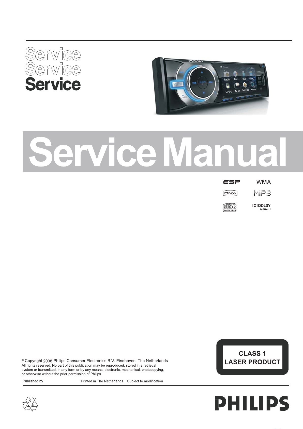
Location of PCBs
1-1
KEY BOARD SERVO BOARD SD BOARD LONG BOARD CONNECT BOARD
VERSION VARIATIONS:
Board inused:
MAIN BOARD
SERVO BOARD
KEY BOARD
CONNECT BOARD
SD BOARD
LONG BOARD
Type/Versions
Service policy
/55 /51
M/C M/C
M/C M/C
C C
C C
C C
C C
MAIN BOARD
CED230(X)
/78
M/C
M/C
C
C
C
C
Type/Versions
Features
* TIPS:C--Component Lever Repair.
M--Module Lever Repair
--Used
Feature diffrence
CED230
/
Page 3

SPECIFICATIONS
General Tuner
Power s upp ly:
Fuse:
Suita ble s peaker impeda nce :
Maxim um po wer output:
Conti nuo us power output :
Pre-A mp ou tput voltage:
Aux-i n lev el:
Dimen sio ns(WxHxD):
Weight:
Disc Player
1-2
12V DC( 11V )
negat ive g round
15A
4-8Ω
45Wx4 cha nnels
18Wx4 cha nnels(4Ω 10% T.H.D.)
2. 0V(CD p lay m ode;1kHz,0dB,
10KΩ loa d)
≥500mV
188x5 8x1 93mm
1. 9kg
-16V
Frequ enc y range
-FM
Frequ enc y range
-AM(M W)
Usabl e sen sitivity
-FM
Usabl e sen sitivity
-AM(M W)( S/N=20dB)
Frequ enc y response
Stere o sep aration
Signa l/n oise ratio
87.5-10 8. 0MH z(Eur)
65.0-74 .0 MHz (OIRT)
87.5-10 7. 9MH z(Ame)
522-1 620 KHz(Eur)
530-1 710 MHz(Ame)
8uV
30uV
30Hz- 15K Hz
30db( 1KH z)
>55dB
Syste m:
Frequ enc y response:
Signa l/n oise ratio:
Total har mon ic distortion :
Chann el se paration:
Video signal fo r mat :
Video output:
LCD
Scree n siz e:
Displ ay re solution:
Activ e are a:
Contr ast r atio:
Brigh tne ss:
Disc di git al audio system
20Hz- 20k H z
>75dB
Less th an 0. 3% (1KHz)
>55dB
NTSC/ PAL/AUTO
1+/0. 2V
3. 0 inche s .
320x2 40 do ts
65.52 (W) x36.84(H)
300
200cd /m
(16 91)
Note:
Specifications and design are subject to change
without notice for product improvements.
Page 4
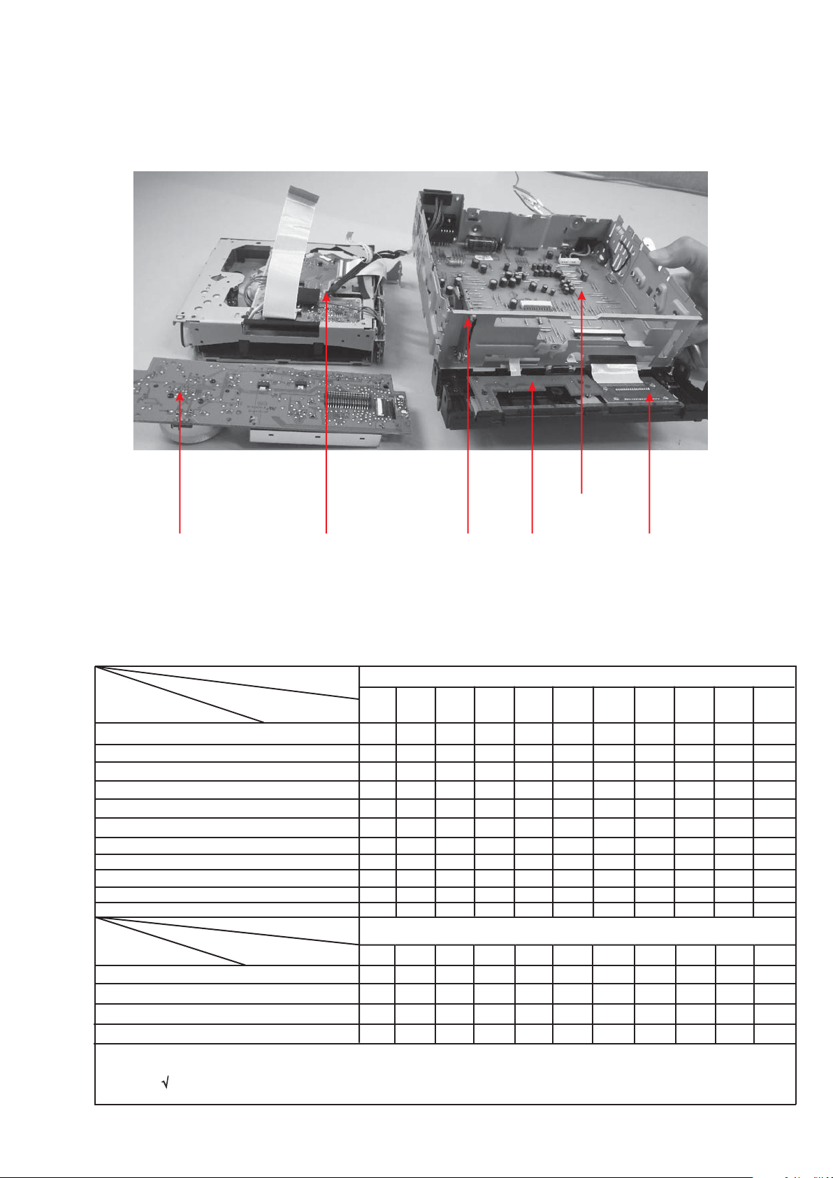
MEASUREMENT SETUP
Tuner FM
1-3
Bandpass
25 0Hz- 15k Hz
e.g . 7122 70 7 48001
LF Voltmeter
e.g . PM253 4
RF Generato r
e.g . PM532 6
DUT
Ri=50Ω
S/N and disto rti on me ter
e.g . Sound Tec hnolo gy ST17 00B
Use a bandpas s fil ter t o eliminate hu m(5 0Hz ,100Hz) and di stu rba nce from th e pil ott one(19kHz, 38k Hz) .
Tuner AM (MW,LW)
RF Generato r
e.g . PM532 6
Ri=50Ω
DUT
Frame aeria l
e.g . 7122 70 7 89001
Bandpass
25 0Hz- 15k Hz
e.g . 7122 70 7 48001
LF Voltmeter
e.g . PM253 4
S/N and disto rti on me ter
e.g . Sound Tec hnolo gy ST17 00B
To avoid atmosp her ic in terference a ll AM- mea surements ha ve to b e car ried out in a Fara day s c age .
Use a bandpas s fil ter ( o r at least a high pa ss fi lte r with 250Hz) to e lim ina te hum ( 50Hz ,10 0Hz ) .
CD
Use Audio Sign al Di sc SB C429 4822 397 30 184
(replaces t est d isc 3 )
DUT
L
Cassette
Use Univers al Test Cassette C rO2 S BC4 19 4822 397 3006 9
or Universa l Te st Cassette Fe S BC4 20 48 22 397 30071
LF Generato r
e.g . PM5110
DUT
R
S/N and disto rti on me ter
e.g . Sound Tec hnolo gy ST17 00B
LEVEL ME TER
e.g . Sennh eiser U PM550
wit h FF-fi lter
'
L
R
S/N and disto rti on me ter
e.g . Sound Tec hnolo gy ST17 00B
LEVEL ME TER
e.g . Sennh eiser U PM550
wit h FF-fi lter
Page 5
SERVICE AIDS
1-4
GB
All ICs and many other semi-conductors are
susceptible to electrostatic discharges (ESD).
Careless handling during repair can reduce life
drastically.
When repairing, make sure that you are
connected with the same potential as the mass
of the set via a wrist wrap with resistance.
Keep components and tools also at this
potential.
WARNING
GB
Safety regulations require that the set be restored to its original
condition and that parts which are identical with those specified,
be used
Safety components are marked by the symbol
!
.
ESD
CLASS 1
LASER PRODUCT
Lead free
Page 6
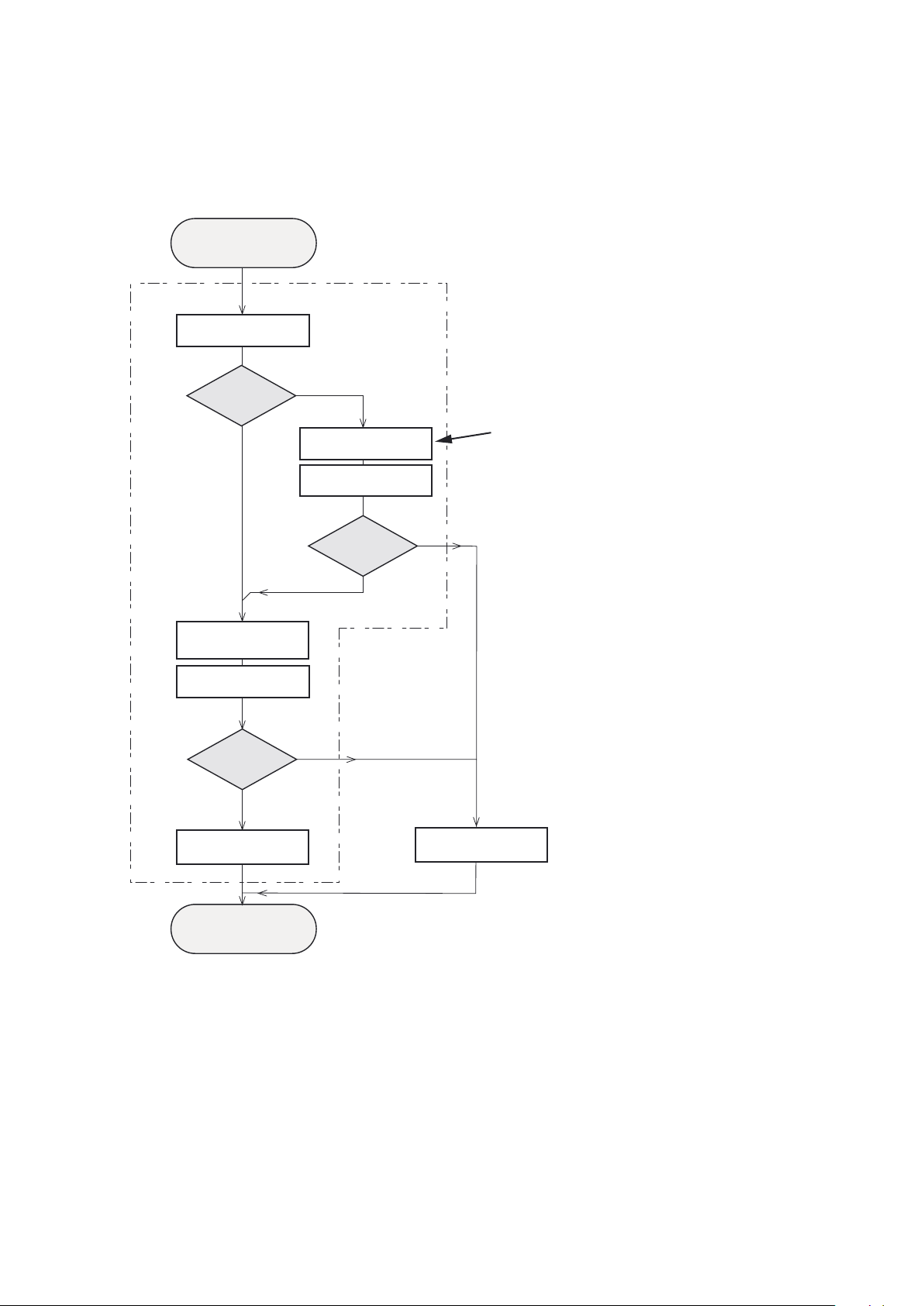
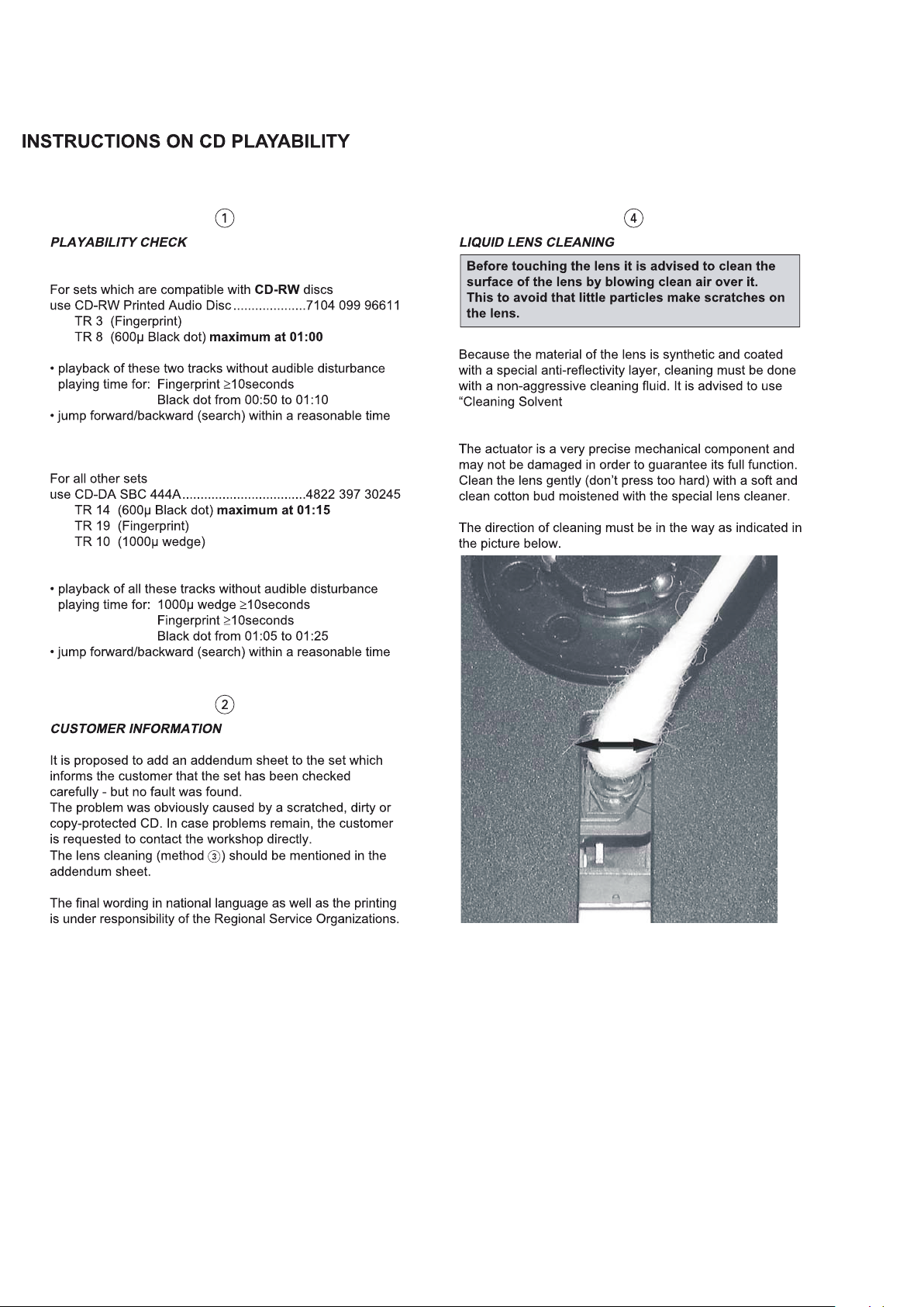
INSTRUCTIONS ON CD PLAYABILITY
Custo mer c omplaint
"CD relat ed pr oblem"
Set remains closed!
Check p lay ability
①
1-5
playa bil ity
ok?
Y
Play a CD
for at lea st 10 m inutes
check playability
playa bil ity
ok?
Y
N
"fast" lens cleaning
check playability
playa bil ity
ok?
Y
N
③
N
For fla p loa ders(=acces s to CD d rive possible )
clesn ing m ethod④is recomm end ed
ann lnfo for cu sto mer
"SET OK "
retur n set
①-④For des cri ption see followin g pag es-
②
Exchange CDM
Page 7
1-6
Page 8
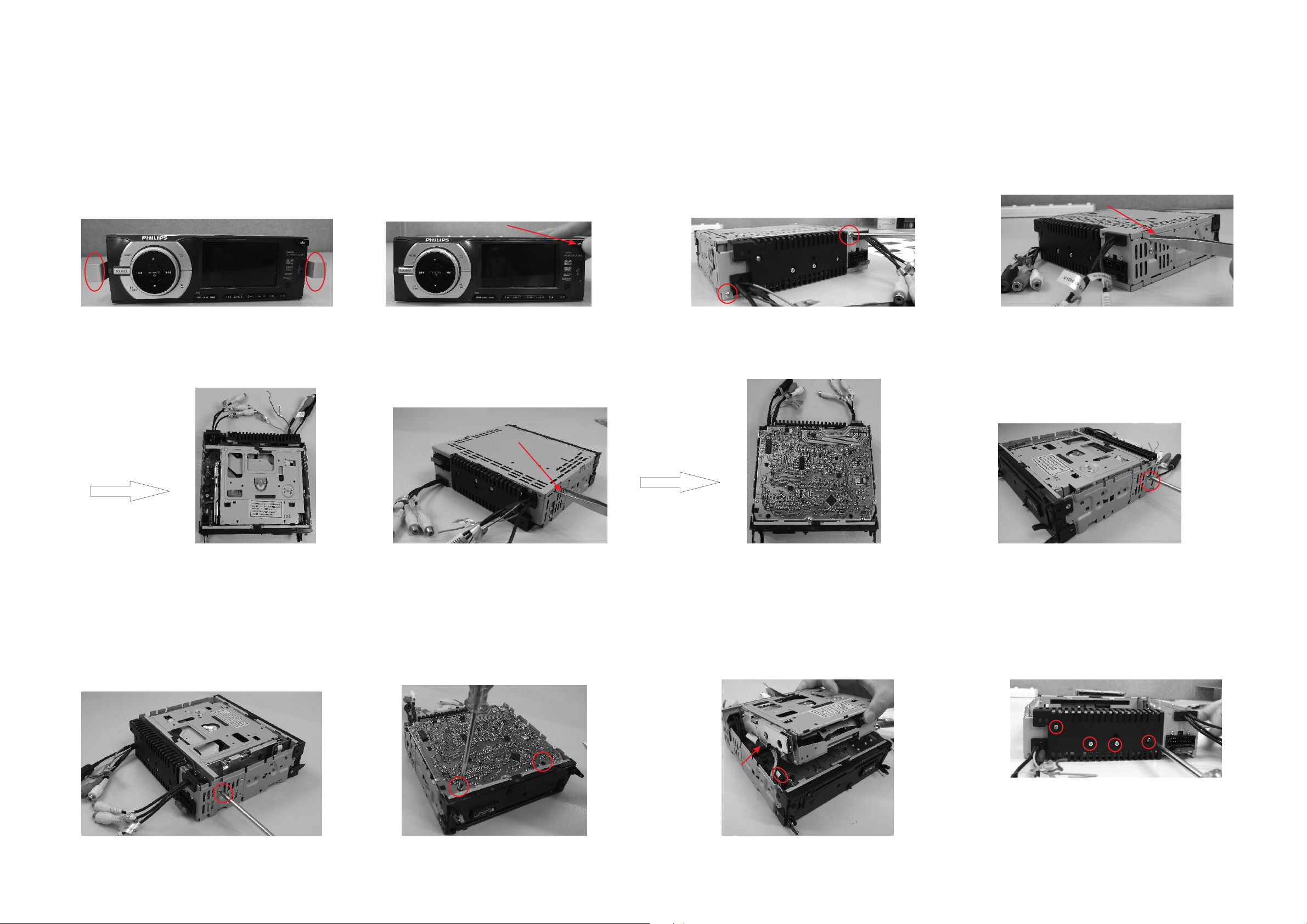
Disassembly Diagram
2-1 2-1
1、P collar
ull out the mounting from the
main set with two L-keys.
2、Press the release key first,
then take out the panel.
5、Take out the bottom cover with a forceps.
3、loosen and take out the two bolts
with a screw-driver.
4、Take out the top cover with a forceps.
6、loosen and take out the bolt
with a screw-driver.
7、loosen and take out the bolt
with a screw-driver.
8、loosen and take out the t bolt
with a screw-driver.
wo s
9、P
ull out the two pieces of connection-pegs 10、loosen and take out the four bolt
carefully
with a screw-driver.
s
Page 9

Disassembly Diagram
2-2 2-2
ull out the two pieces of connection-pegs
14、P
carefully
、
11 loosen and take out the bolt
with a screw-driver,
15、Loosen and take out the six bolts
with a screwdriver.
、
12 loosen and take out the bolt
with a screw-driver,
、
13 loosen and take out the bolt
with a screw-driver,
Page 10

3-1 3-1
Software version check & upgrade Upgrade software
Check MCU software version
1. Copy the file "MCU.BIN" into USB stick
2. Power on the device, and plug the USB stick into USB socket.
After the device read the content in the USB, the LCD will show
a upgrade menu, and enter into the upgrading status.
3. The LCD wi ll appear a number (changed from 20 to 0), and when
arrived the number 0, then appear a processing bar, which mean
the device enters upgrading status.
4. In step 3. if want to enter into upgrading status quickly, press the
key OKto confirm, the processing bar will appear immediately.
5. Disconnect the USB stick.
6. When software upgrade complete, the device will power off automatically.
Check Servo software version
When the device is power on at the first time, in USB/SD/Disc mode,
press the key in turn:
stop up down left right
The LCD will display the servo software, MCU, TFT version num ber.
1. Copy the file "ROM.BIN" into USB stick (note to delete the file "MCU.BIN" ).
2. Power on the device, and plug the USB stick into USB socket. After the
device read the content in the USB, the LCD will show a upgrade menu,
and enter into the upgrading status.
3. The LCD wi ll appear a number(changed from 20 to 0), and when arrived
the number 0, then appear a processing bar, which mean the device enters
upgrading status.
4. Press the key OK to confirm, the processing bar will appear immediately.
5. Disconnect the USB stick.
6. When software upgrade complete, the device will change to disc mod e automatic ally.
Page 11

Malfunction check chart
3-2 3-2
Main bo ard w hich in
NO
NO
TDA73 88 of m ain
NO
Main bo ard
Check t une r circuit
and its c onj oint part
is good o r bad
NO
NO
NO
Chang e mai n
NO
NO
NO
SD no rea d
Wheth er co nnect to SD
Check t he so cket of SD
SD
Chang e ser vo
USB no re ad
Whether con nec t to US B
Check the soc ket o f USB
SD
Chang e ser vo
Page 12

WIRING DIAGRAM
4-1 4-1
Page 13

MAIN BOARD-CIRCUIT DIAGRAM-1
5-1 5-1
Page 14

MAIN BOARD-CIRCUIT DIAGRAM-2
5-2 5-2
Page 15

5-3 5-3
MAIN BOARD-PCB LAYOUT TOP/BOTTOM VIEW
Page 16

SERVO BOARD-CIRCUIT DIAGRAM-1
6-1 6-1
Page 17

SERVO BOARD-CIRCUIT DIAGRAM-2
6-2
6-2
Page 18

6-3 6-3
SERVO DIAGRAM BOARD-LAYOUT TOP/BOTTOM VIEW
Page 19

SB+CB BOARD-CIRCUIT DIAGRAM
7-1 7-1
Page 20

7-2
SB+CB BOARD-PCB LAYOUT TOP/BOTTOM VIEW
7-2
Page 21

LB+SD+CB BOARD-CIRCUIT DIAGRAM
8-1 8-1
Page 22

8-2 8-2
LB+SD PCB+CB BOARD- LAYOUT TOP/BOTTOM VIEW
Page 23

KEY BOARD-CIRCUIT DIAGRAM
9-1 9-1
Page 24

9-2 9-2
KEY BOARD-LAYOUT DIAGRAM TOP/ VIEWBOTTOM
Page 25

EXPLODED VIEW-MAIN UNIT
10-1 10-1
 Loading...