


Philips CDR775 Service Manual
Compact disc recorder
Service
CDR775
/oo
nCOJJPACT riBOMfWCT nOOMPACT HCOMPACT
togl
(ta
MOfTAlAUOtO MBtTAl AUDIO
oEtascB
PtGfTAlAUMO OHHTAL AUDIO
GQD§(S
SERVICING
For servicing CDR775, the set can divided into three parts.
1.
The display board (partly) 1 002, the I/O board 1004, the
headphone board (partly)
OFF & Standby LED board (partly) 1002 and the CD-out board
(partly) 1002 have to be repaired at component level. The power
supply unit 1003 is available as spare part, but can also be repaired
at component level.
2.
The CDR module (containing the CDR loader
1001 and loader bracket 82, 83) will be exchanged completely in
case of failure. This complete CDR module is available as spare
part. Defective modules have to be returned for central repair.
3. The CD module (containing the CD loader
1005 and loader bracket 132) is a new module with VAL1250
loader assy but also a separate CDM and separate loader
be available via service stock. The CD main board can be repaired
at component level.
Also available: Circuit Description " The Basics of Compact Disc
Recordable/Rewriteable". Service code number 4822 725 25242.
1002,
the IR board (partly) 1002, the ON/
81,
CDR main board
131,
CD main board
parts
will
Contents
1.
Technical Specifications
2.
Warning and Servicing Hints
3. User Instructions
4.
Mechanical Instructions
Wiring Diagram CDR
Wiring Diagram CD loader
Exploded View CDR
Exploded View CD loader
Dismantling Instructions
5. Electrical and Circuit Diagrams
Overall Blockdiagram
Display Board
IR / On/Off &Standby LED Board
Headphone / CD-out Board
I/O Board
Power supply unit
CD-Mainboard 1A
CD-Mainboard 1B
CD-Mainboard 1C
CD-Mainboard 2
6. Diagnostic Software
7. Faultfinding Trees
8. Faultfinding Guide
9. List of Abbreviations
10.
Partslist (mechanical and electrical)
Page
2
4
7
19
19
20
21
22
23
Diagram PWB
24
26
27
28
29
31
33
34
35
36
39
43
49
65
71
26
27
28
30
32
37/38
37/38
37/38
37/38
Copyright reserved 1999 Philips Consumer Electronics B.V. Eindhoven, The
Netherlands. All rights reserved. No part of this publication may be reproduced,
stored in a retrieval system or
mechanical, photocopying, or otherwise without the prior permission of Philips.
Published by RH 9969 Service DPS Hasselt
transmitted,
in any
form
or
by
Printed in the Netherlands
any
means,
electronic,
Subject to modification
PHILIPS
<§§> 3104 125 40030
Warnings and Servicing Hints
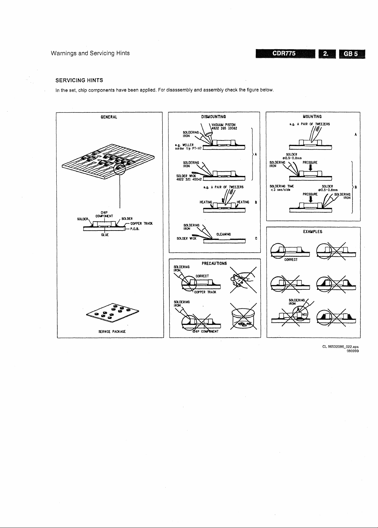
SERVICING HINTS
In the set, chip components have been applied. For disassembly and assembly check the figure below.
CL 96532086_022.eps
080999
CDR775
Warnings and Servicing Hints
SAFETY GUIDELINES FOR THE PROFESSIONAL SERVICE TECHNICIAN
Important
Proper service and repair is Important to the safe, reliable operation
of all Philips equipment. The service procedures recommended by
Philips and described In this service manual are effective methods of
performing service operations. Some of these service operations
require the use of tools specially designed for the purpose. The
special tools should be used when and as recommended,
It is Important to note that this manual contains various CAUTIONS
and NOTICES which should be carefully read In order to minimize the
risk of personal injury to service personnel. The possibility exists
that Improper service methods may damage the equipment. It also
Is Important to understand that these CAUTIONS and NOTICES
ARE NOT EXHAUSTIVE, Philips could not possibly know, evaluate
and advise the service trade of all conceivable ways In which service
might be done or of the possible hazardous consequences of each
way. Consequently, Philips has not undertaken any such broad
evaluation.
tool which Is not recommended by Philips must first satisfy himself
thoroughly that neither his safety nor the safe operation of the
equipment will be Jeopardized by the service method selected.
Safety Checks
After the original service problem has been corrected, a complete
safety check should be made. Be sure to check over the entire set,
not Just the areas where you have worked. Some previous servicer
may have left an unsafe condition, which could be unknowingly
passed on to your customer. Be sure to check all of the following:
Accordingly, a servicer who uses a service procedure or
Fire and Shock Hazard
1.
Be sure all components are positioned In such a way as to avoid
the possibility of adjacent component shorts. This is especially
important on those units which are transported to and from the
service shop.
2.
Never release a repaired unit unless all protective devices such
as insulators, barriers, covers, strain reliefs, and other
hardware have been installed according to the original design,
3. Soldering and wiring must be inspected to locate possible cold
solder Joints, solder splashes, sharp solder points, frayed
leads,
pinched leads, or damaged Insulation (Including the ac
cord).
Be certain to remove loose solder balls and aH other
loose foreign particles.
4.
Check across-the-line components and other components for
physical evidence of damage or deterioration and replace if
necessary. Follow original layout, lead length, and dress.
5. No lead or component should touch a resistor rated at 1 watt or
more.
Lead tension around protruding metal surfaces or edges
must be avoided.
6. Critical components having special safety characteristics are
Identified with a Aby the Ref. No. In the parts list and enclosed
within a broken line* (where several critical components are
grouped In one area) along with the safety symbol
A on the schematic diagrams and/or exploded views.
Replacement parts without the same safety characteristics
may create shock, fire, or other hazards.
7. When servicing any unit, always use a separate Isolation
transformer for the chassis. Failure to use a separate isolation
transformer may expose you to possible shock hazard, and
may cause damage to servicing instruments.
8. Many electronic products use a polarized ac line cord (one wide
pin on the plug). Defeating this safety feature may create a
potential hazard to the servicer and the user. Extension cords
which do not Incorporate the polarizing feature should n»ver be
used.
Fire and Shock Hazard (Continued)
9, After reassembly of the unit, always perform an ac leakage
test or resistance test from the line cord to all exposed metal
parts of the cabinet, Also, check all metal control shafts (with
knobs removed), antenna terminals, handles, screws, etc. to
be sure the unit Is safe to operate without danger of electrical
shock,
Broken line: an
Leakage Current Cold Check
Unplug the ac line cord and connect a Jumper between the two
1,
prongs of the
Turn on the power switch.
Measure the resistance value between the Jumpered ac plug
and all exposed cabinet parts of the receiver, such as screw
heads, antennas, and control shafts. When the exposed
metallic part has a return path to the chassis, the reading
should be between 1 megohm and 5.2 megohms. When the
exposed metal does not have a return path to the chassis, the
reading must be Infinity. Remove the jumper from the ac line
cord.
TO
INSTRUMENTS
EXPOSED
METAL PARTS
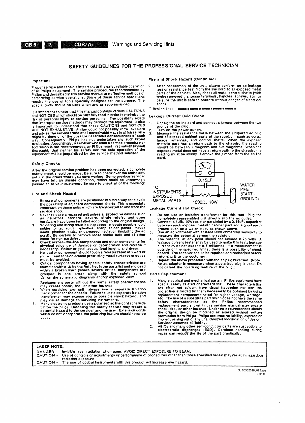
Leakage Current Hot Check
1.
Do not use an isolation transformer for this test. Plug the
completely reassembled unit directly into the ac outlet.
2.
Connect a 1.5k, 10W resistor paralleled by a 0,15uF. capacitor
between each exposed metallic cabinet part and a good earth
ground such as a water pipe, as shown above.
3. Use an ac voltmeter with at least 5000 ohms/volt sensitivity to
measure the potential across the resistor.
4.
The potential at any point should not exceed 0.75 volts. A
leakage current tester may be used to make this test; leakage
current must not exceed 0.5 mllllamps. If a measurement Is
outside of the specified limits, there Is a possibility of shock
hazard.
returning It to the customer.
5. Repeat the above procedure with the ac plug reversed. (Note:
An ac adapter Is necessary when a polarized plug Is used. Do
not defeat the polarizing feature of the plug.)
Parts Replacement
1.
Many electrical and mechanical parts In Philips equipment have
special safety related characteristics. These characteristics
are often not evident from visual inspection nor can the
protection afforded by them necessarily be obtained by using
replacement components rated for higher voltage, wattage,
etc. The use of a substitute part which does not have the same
safety characteristics as the Philips recommended
replacement part shown in this service manual may create
shock, fire, or other hazards. Under no circumstances should
the original design be modified or altered without written
permission from Philips. Philips assumes no liability, express or
implied,
Servicer assumes all liability.
2.
All ICs and many other semiconductor parts are susceptible to
electrostatic discharges (ESD). Careless handling during
repair can reduce the life of the part drastically.
plug,
WATER
PIPE
(EARTH
1500H,
10VV
The receiver should be repaired and rechecked before
arising out of any unauthorized modification of design.
GROUND)
LASER NOTE:
DANGER - Invisible laser radiation when open. AVOID DIRECT EXPOSURE TO BEAM.
CAUTION - Use of controls or adjustments or performance of procedures other than those specified herein may result in hazardous
CAUTION - The use of optical Instruments with this product will Increase eye hazard.
radiation exposure.
CL 96532086_023.eps
080999
Diagnostic Software
6. Diagnostic Software
6.1 Dealer mode
The purpose of the dealer mode is to prevent people taking out
the CD inside the player at exhibitions, showrooms etc.. This
mode disables the open/close function of the player,
The dealer mode can be switched on and off pressing keys
[OPEN/CLOSE] and [STOP] of
while switching on the unit. The dealer mode is stored in the
flash memory
actions.
and
can only be changed by executing the above
the
CDR player simultaneously
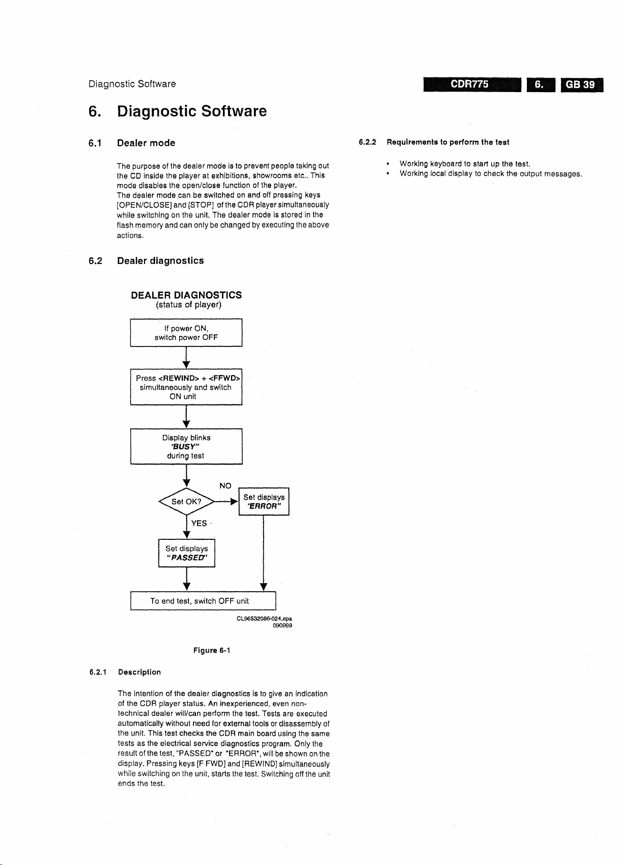
6.2 Dealer diagnostics
6.2.2 Requirements to perform the test
• Working keyboard to start up the test.
• Working local display to check the output messages.
CL96532086-024.eps
Figure 6-1
6.2.1 Description
The intention of the dealer diagnostics is to give an indication
of the CDR player status. An inexperienced, even
technical dealer will/can perform the test. Tests are executed
automatically without need for external tools or disassembly of
the unit. This test checks the CDR main board using the same
tests as the electrical service diagnostics program. Only the
result of
the
test,
display. Pressing keys [F FWD] and [REWIND] simultaneously
while switching on the unit, starts the test. Switching off
ends the test.
"PASSED" or "ERROR", will
090999
non-
be
shown on the
the
unit
CDB775
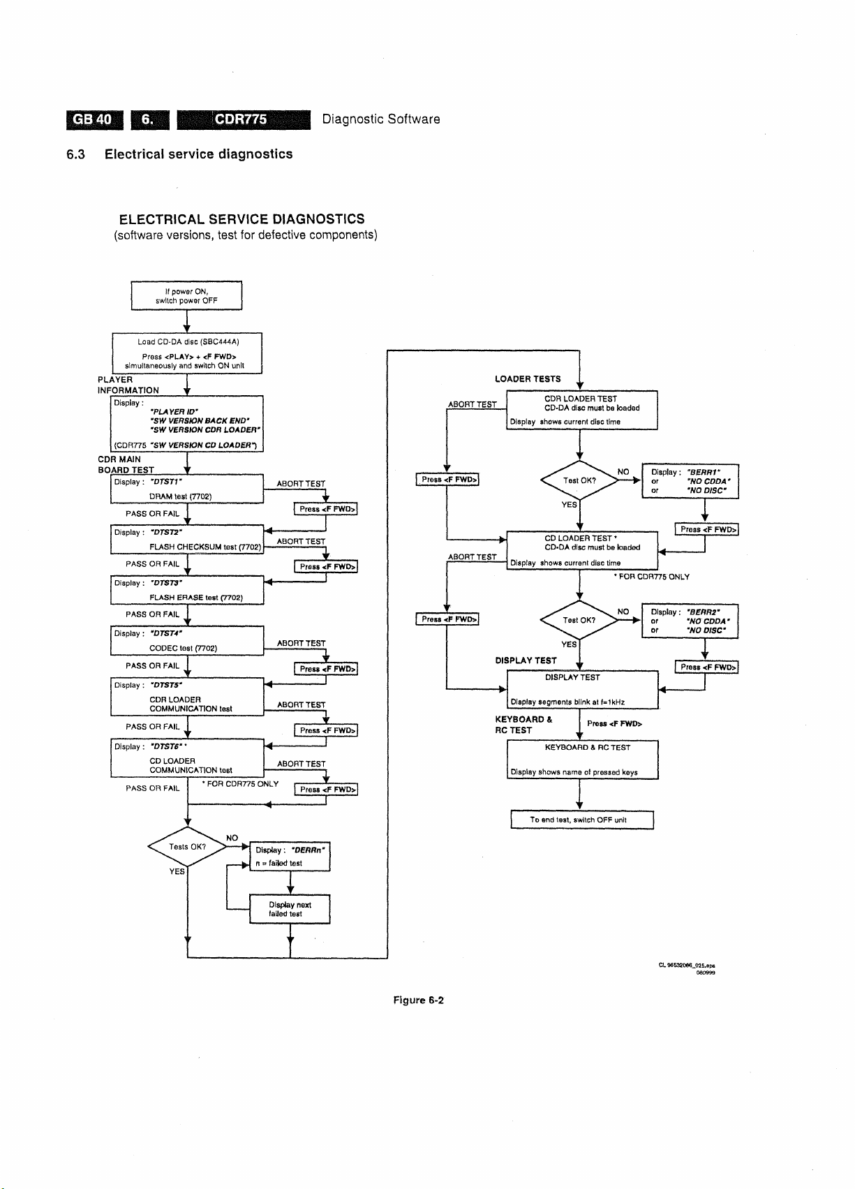
6.3 Electrical service diagnostics
ELECTRICAL SERVICE DIAGNOSTICS
(software
versions,
test for defective components)
Diagnostic Software
Figure 6-2
Diagnostic Software
CDR775
6.3.1 Description
The intention of the electrical service diagnostics is to show the
software versions present in the player and to direct the dealer
towards defective internal units. The units are : the CDR main
board,
the CDR loader, the CD loader
the keyboard/display board. A sequence of tests is executed
automatically. Some of the tests can be aborted or skipped
without the result being taken Into account. External tools or
disassembly of the unit is not necessary to get the diagnostic
information. Pressing keys [PLAY/PAUSE] and [F FWD]
simultaneously while switching on the unit, starts the test.
Switching off the unit ends the test.
6.3.2 Requirements to perform the test
• Working keyboard to start up the test.
• Working local display to check the output messages.
• A CD-DA disc with a minimum of 3 tracks in all trays to
perform the disc test.
6.3.3 Description of the tests
Player
Information
In this part of
checked without removing the cover:
• SW-version back end of player.
• SW-version CD loader (only for CDR775).
CDR main board
[F FWD] key. The message "DERRn" will be displayed with n
indicating the faulty test number.
If one of the tests is aborted with the [F FWD] key, no error
message will be displayed for this test. The flash data erase
test
("DTST3")
The CDR main board test consists out of:
the
test the following Important Information can be
Recorder ID.
SW-version CDR loader.
test
can not be aborted !
in
case of a CDR775 and
disc test is executed to check focus control, disc motor control,
radial control and jump grooves control. The disc test is
performed by audio play-back of 5 seconds at the beginning,
middle and end of the disc.
CDR
loader
During the test, the current disc time is shown. In case of an
error the message
key must be pressed to continue with the following test.
Pressing the [F FWD] key also aborts this test.
CD loader
For CDR775 only. During the test, the current disc time is
shown.
displayed and the [F FWD] key must be pressed to continue
with the following test. Pressing the [F FWD] key also aborts
this test.
Display test
All segments will blink at a frequency of 1 Hz. Pressing the [F
FWD] key will start the next test because the user has to check
for himself if all segments work properly.
Keyboard
The test will give the user the ability to test every key without
executing the function assigned to
to press every key
display will show the name of the key being pressed. Pressing
more than one key at once will give an unpredictable result
except for
[PLAY/PAUSE] + [F FWD], [F FWD] + [REWIND], [ERASE] +
[RECORD], [PLAY/PAUSE] + [RECORD], [OPEN/CLOSE] +
[PROGRAM].
test
"BERR1"
test
In case of an error the message "BERR2" will be
and
remote
on
the
service combinations: [PLAY/PAUSE] + [STOP],
will be displayed and the [F FWD]
control tests
it.
the keyboard and the remote
Therefore, the user needs
6.4 Mechanical service diagnostics
control.
The
DRAM test
Display :
tested by writing, reading and verifying test patterns.
CDR950.
tested.
processor (DASP) and the CD loader is
applicable for CDR775.
These tests determine if the CDR loader and the CD loader in
case of a CDR775 work correctly. A CD-DA disc with a
minimum of 3 tracks needs to be inserted in both loaders. A
"DTST1",
Flash
checksum
Display : "DTST2". This test checks the checksum of the
player's SW stored in the flash.
Flash data erase
Display : "DTST3". During this test, all temporary information
(CDtxt) in the flash is erased.
CODEC
(ADC/DAC)
Display : "DTST4". This test checks the CODEC IC by writing,
reading and verifying test
CDR
communication
Display : "DTST5". The communication between the host
processor (DASP) and the CDR loader via the DSA-R-bus is
CD
communication
Display : "DTST6"). The communication between the host
Loader tests
The DRAM used for buffer management is
test
test
patterns.
test
test
The test is not applicable for
tested.
The test is only
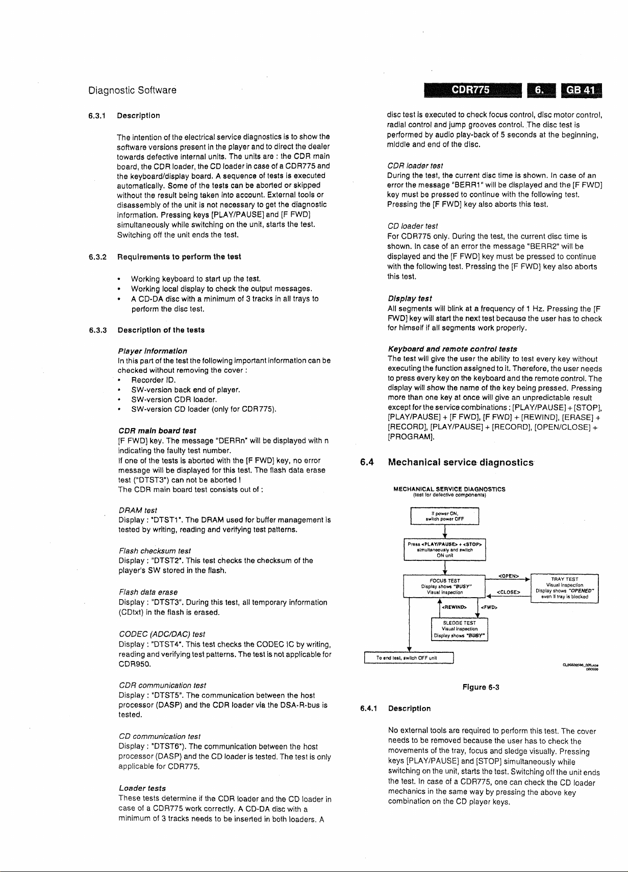
6.4.1 Description
No external tools are required to perform this test. The cover
needs to be removed because the user has to check the
movements of the tray, focus and sledge visually. Pressing
keys [PLAY/PAUSE] and [STOP] simultaneously while
switching on the unit, starts the
the test. In case of a CDR775, one can check the CD loader
mechanics in the same way by pressing the above key
combination on the CD player keys.
test.
Switching off the unit ends

BSEM HH
IHQ^^HH Diagnostic Software
6.4.2 Requirements to perform the test
• Working keyboard to cycle through the tests and to start up
the test.
Working local display to check the output messages.
6.4.3 Description of the tests
Focus control test
The focussing lens is continuously moving up and down. The
display reads "BUSY".
Sledge control test
After pressing [F FWD] the sledge continuously moves up and
down.
Pressing [REWIND] stops the sledge at the position it is
in and the focus control test resumes. The display reads
"BUSY".
Tray control test
This test starts from within the focus control test routine.
Pressing [OPEN/CLOSE] moves the tray in or out. In the tray
open position one can initiate focus and sledge tests by
pressing [F
[REWIND] before it is possible to close the tray again.
Depending on the action the display reads "OPEN",
"OPENED",
6.5 DC-erase service mode
FWD].
One has to stop these tests pressing
"CLOSE" or "BUSY".
i.5.1 Description
This test is initiated by pressing [ERASE] and [RECORD]
simultaneously while switching on the unit. The player will
erase a complete CD-RW disc (including PMA and ATIP lead
out area) at speed N=2. The display shows the countdown of
the remaining time required for the operation to complete, The
format is "ER mm:ss", where "mm" are the remaining minutes
and
"ss"
the remaining seconds. After completion the message
"PASSED"
on again to start up in normal operating
unit before completion of the test, leaves the disc in an
unpredictable state. In such case only a complete DC-erase
procedure can recover the CD-RW disc.
5.5.2 Requirements to perform the test
•• Functional CDR player.
* A CD-RW audio disc must be present in the tray.
is shown, and the player has to be switched off and
mode.
Switching off the
Figure 6-4
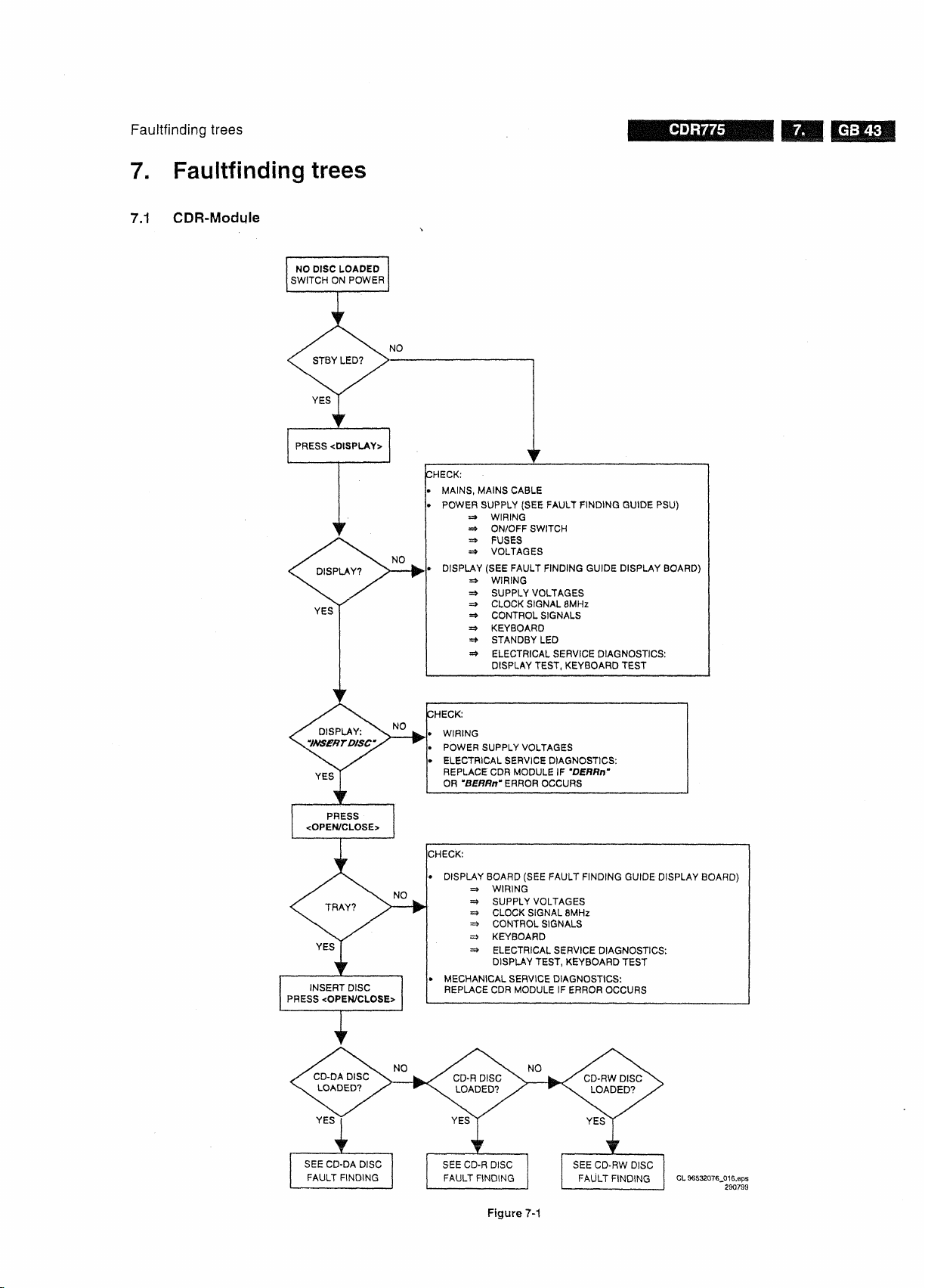
Faultfinding trees
7. Faultfinding trees
7.1 CDR-Module
CDR775
Figure 7-1
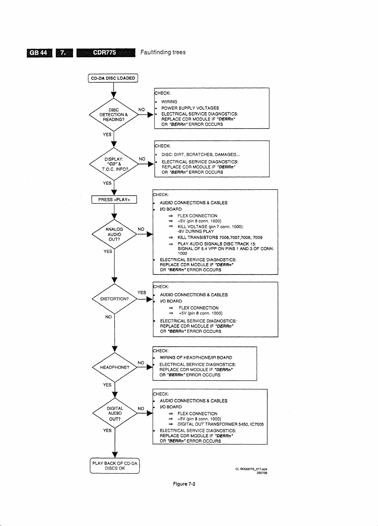
CDR775
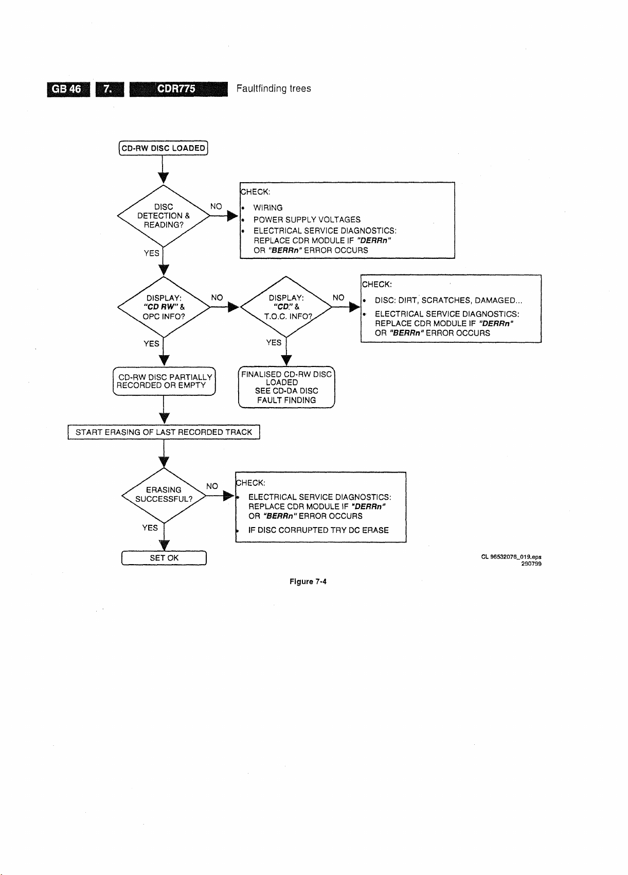
Faultfinding trees
Figure
7-2
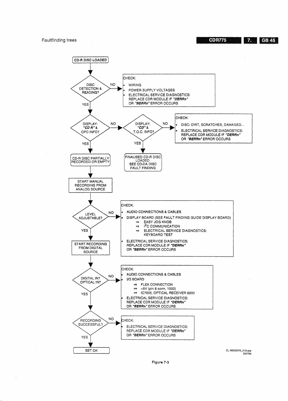
Faultfinding trees
CDR775
Figure
7-3
CDR775
Faultfinding trees
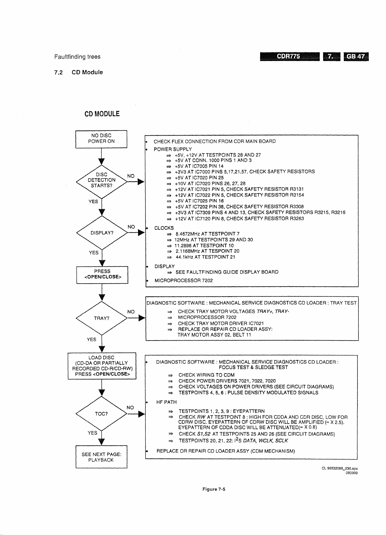
Faultfinding trees
7.2 CD Module
C0R775
•pMiiiap»|»iMM
Figure 7-5

CDR775
Faultfinding trees
Faultfinding Guide
8. Faultfinding Guide
CDR775
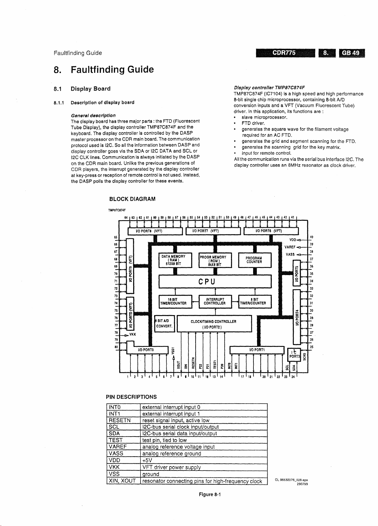
8.1 Display Board
8.1.1 Description
General description
The display board has three major parts : the FTD (Fluorescent
Tube Display), the display controller TMP87C874F and
keyboard.
master processor
protocol used
display controller goes via the SDA
I2C CLK lines. Communication is always initiated by the DASP
on the CDR main board. Unlike the previous generations
CDR players, the interrupt generated by the display controller
at key-press or reception of remote control is not
the DASP polls the display controller for these events.
of
display board
The display controller Is controlled by the DASP
on
the CDR main
is
I2C. So all the information between DASP and
board.
The communication
or
I2C DATA and SCL or
used.
the
of
Instead,
Display controller TMP87C874F
TMP87C874F (IC7104) Is a high speed and high performance
8-bit
single chip microprocessor, containing
conversion inputs and a VFT (Vacuum Fluorescent Tube)
driver. In this application, its functions are
• slave microprocessor.
• FTD driver,
• generates the square wave for the filament voltage
required for an AC FTD.
• generates the grid and segment scanning for the FTD.
• generates the scanning grid
• input
for
remote control.
All
the communication runs via the serial bus interface I2C. The
display controller uses an 8MHz resonator as clock driver.
for
8-bit
A/D
:
the key matrix.
PIN DESCRIPTIONS
INTO
INT1
RESETN
SCL
SDA
TEST
VAREF
VASS
VDD
VKK
VSS
XIN,
XOUT
external interrupt input 0
external interrupt input 1
reset signal input, active low
l2C-bus serial clock input/output
l2C-bus serial data input/output
test pin, tied to low
analog reference voltage input
analog reference ground
+5V
VFT driver power supply
ground
resonator connecting pins for high-frequency clock
Figure 8-1
CL 96532076_028.eps
290799
CDR775
Faultfinding Guide
8.1.2 Test instructions
Supply
voltages
The display board receives several voltages via connector
1119 (and connector
• VFTD : -38V ±5% measured at pin 2 of conn. 1119.
• VDC1-VDC2 : 3V8
conn.
• +5V : +5V ±5% measured at pin 10 of
Voltages VFTD, VDC1 and VDC2 are produced in the power
supply unit and sent to the display board via the CDR main
board.
D5V.
Clock
As clock driver for the display controller, a resonator of 8 MHz
(1110) is used. The signal can be measured at pins 8 and 9 of
the display controller: 8 MHz ±5%.
Control signals
RESET
The reset signal comes via pin 4 of conn. 1119 from the DASP
master processor
reset is low active. It should be kept low during power up for at
least 3 machine cycles with supply voltage in operating range
and a stable clock signal
sec).
The high signal is 3V3 because the DASP operates on 3V3.
I2CDA
These lines connect to the DASP master processor via
respectively pin 5 and pin 7 of
and pin 1 of conn. 1121 for CDR570/930). When there Is no
communication, they should have the high level (+5V), The
oscillogram below gives an indication of how these signals
should look like.
1119.
conn.
1121 for CDR770).
The +5V voltage is produced on the CDR main board as
signal
During normal
TA/I2C
1121
for CDR570/930).
±10%
measured between pin 1 and 3 of
conn.
on
the CDR main board (SYS_RESET). The
(1
machine cycles 12 x
operation,
CLK
the reset should be high (3V3).
conn.
1119 (pin 5 of
1119 (pin 4 of
1/Fc(8MHz)
conn.
1119
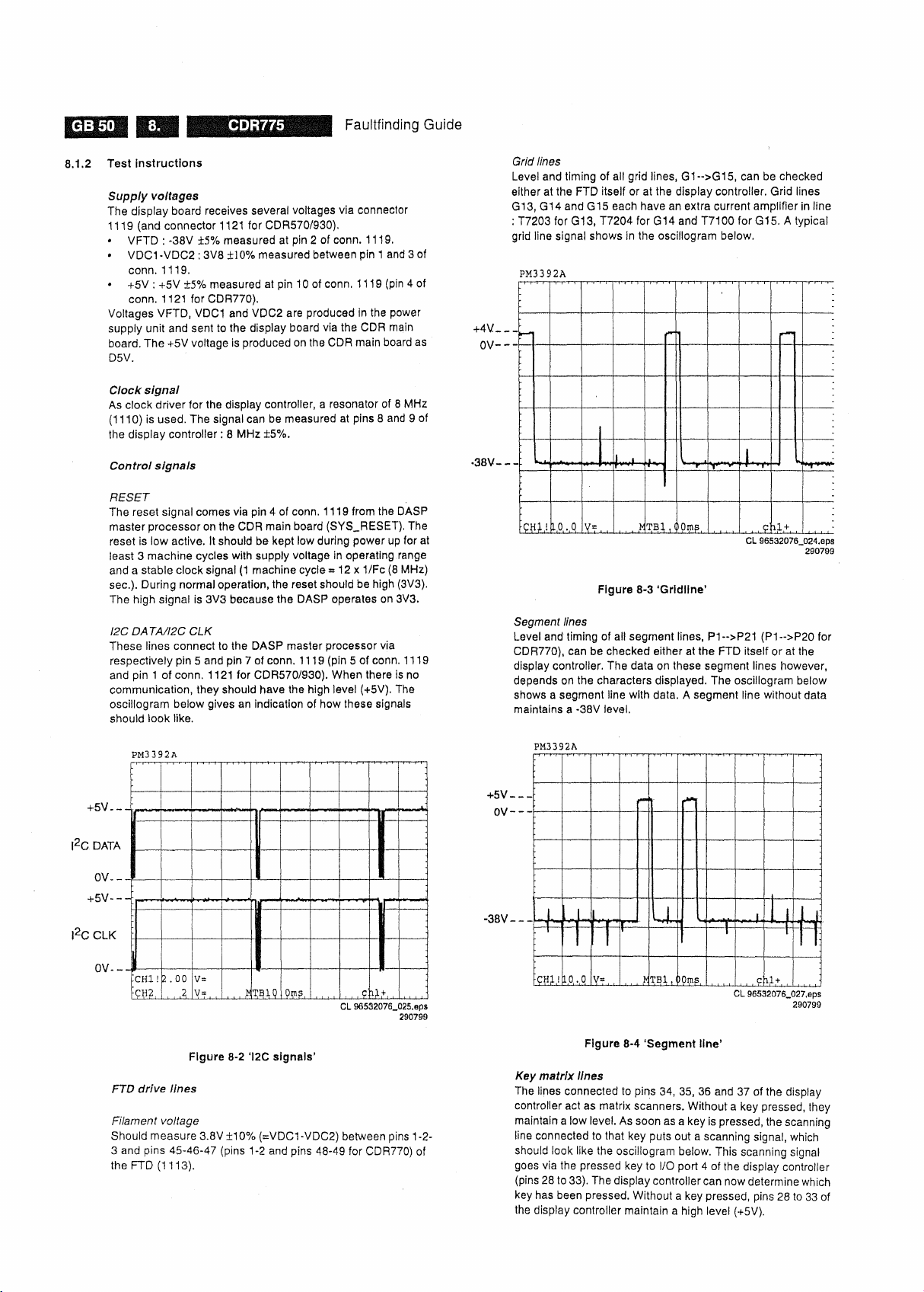
Grid lines
Level and timing of all grid lines, G1-->G15, can be checked
either at the FTD itself or at the display controller. Grid lines
G13,
G14andG15 each have an extra current amplifier in line
: T7203 for G13, T7204 for G14 and T7100 for G15, A typical
grid line signal shows in the oscillogram below.
Figure 8-3 'Gridline'
Segment lines
Level and timing of all segment lines, P1-->P21 (P1-->P20 for
CDR770), can be checked either at the FTD itself or at the
display controller. The data on these segment lines however,
depends on the characters displayed. The oscillogram below
shows a segment line with data. A segment line without data
maintains a -38V level.
Figure 8-2 'I2C signals'
FTD drive lines
Filament voltage
Should measure 3.8V ±10%
3 and pins 45-46-47 (pins 1-2 and pins 48-49 for CDR770) of
the FTD (1113).
(=VDC1
-VDC2) between pins 1 -2-
Figure 8-4 'Segment line'
Key matrix lines
The lines connected to pins 34, 35, 36 and 37 of the display
controller act as matrix scanners. Without a key pressed, they
maintain a low
line connected to that key puts out a scanning signal, which
should look like the oscillogram below. This scanning signal
goes via the pressed key to I/O port 4 of the display controller
(pins 28 to
key has been pressed. Without a key pressed, pins 28 to 33 of
the display controller maintain a high level (+5V).
level.
As soon as a key is pressed, the scanning
33).
The display controller
can
now determine which