


CDC 775
Compact Disc Changer
CDC775
Untitled-19 6/15/00, 1:34 PM1
1
3139 116 17401

English
Important notes for users in the U.K.
Mains plug
This apparatus is fitted with an approved 13 Amp plug. To change a fuse in this
type of plug proceed as follows:
1 Remove fuse cover and fuse.
2 Fix new fuse which should be a BS1362 5 Amp, A.S.T.A. or BSI approved type.
3 Refit the fuse cover.
If the fitted plug is not suitable for your socket outlets, it should be cut off and an
appropriate plug fitted in its place.
If the mains plug contains a fuse, this should have a value of 5 Amp. If a plug
without a fuse is used, the fuse at the distribution board should not be greater
than 5 Amp.
Note: The severed plug must be disposed of to avoid a possible shock hazard
should it be inserted into a 13 Amp socket elsewhere.
How to connect a plug
The wires in the mains lead are coloured with the following code: blue = neutral
(N), brown = live (L).
As these colours may not correspond with the colour markings identifying the
terminals in your plug, proceed as follows:
• Connect the blue wire to the terminal marked N or coloured black.
• Connect the brown wire to the terminal marked L or coloured red.
• Do not connect either wire to the earth terminal in the plug, marked E (or e) or
coloured green (or green and yellow).
Before replacing the plug cover, make certain that the cord grip is clamped over
the sheath of the lead - not simply over the two wires.
Copyright in the U.K.
Recording and playback of material may require consent. See Copyright Act 1956
and The Performer’s Protection Acts 1958 to 1972.
Italia
DICHIARAZIONE DI CONFORMITA’
Si dichiara che l’apparecchio CDC775 Philips
risponde alle prescrizioni dell’art. 2 comma 1 del
D.M. 28 Agosto 1995
n. 548.
Fatto a Eindhoven , il 31/12/1998
Philips Consumer Electronics
5616 JB Eindhoven, The Netherlands
Philips, Glaslaan 2
Norge
Typeskilt finnes på apparatens underside.
Observer:
Den innebygde netdelen er derfor ikke frakoplet
nettet så lenge apparatet er tilsluttet
nettkontakten.
For å redusere faren for brann eller elektrisk
støt, skal apparatet ikke utsettes for regn eller
fuktighet.
Nettbryteren er sekundert innkoplet.
2
Untitled-19 6/15/00, 1:34 PM2
3139 116 18631

INDEX
CLASS 1
LASER PRODUCT
English .....................................4
Français .................................17
Español ..................................30
Deutsch ..................................43
Nederlands ............................ 56
Italiano ...................................69
Svenska .................................82
Dansk .....................................95
Suomi ...................................108
Português ............................121
∂ППЛУИО¿
............................ 134
EnglishFrançais
Español
DeutschNederlandsItalianoSvenskaDanskSuomiPortuguês∂ППЛУИО¿
Untitled-19 6/15/00, 1:34 PM3
3
3139 116 18631

4
English
Thank you for selecting the Philips CDC 775
Compact Disc Changer.
A Compact Disc Changer of the state-of-the-art Philips
700 series, the CDC 775 combines supreme playback
quality with a high degree of user-friendliness by
offering the following possibilities:
– able to play CD-RW disc;
– changing CDs during play;
– quick access to a particular CD by means of QUICK
PLAY;
– storing 40 tracks from different CDs in any desired
order in the changer memory;
– storing the required recording time and playing time
in the EDIT mode.
Power Supply Setting
• Check that the type plate on the rear of your changer
indicates the correct supply voltage.
• If your mains supply voltage is different, consult your
dealer or our Service Organisation.
Siting the Compact Disc Changer
Free standing
• Always position the changer horizontally on a flat,
firm surface.
• Allow a free space of at least 3 cm above the
changer so as not to interfere with the cooling of the
changer.
In an audio rack
• The changer can be sited in any desired position.
Stacked
• Site the changer preferably at the bottom or at the
top.
• Never position the changer directly on top of a highpower amplifier, as such an amplifier gives off a
substantial amount of heat.
Introduction . . . . . . . . . . . . . . . . . . . . . . .4
Installation . . . . . . . . . . . . . . . . . . . . .4 - 5
Functional Overview . . . . . . . . . . . . .6 - 8
Playback . . . . . . . . . . . . . . . . . . . . . .9 - 13
Programming . . . . . . . . . . . . . . . . . . . . .13
Edit . . . . . . . . . . . . . . . . . . . . . . . . . .14 - 15
Additional Information . . . . . . . . .15 - 16
Troubleshooting . . . . . . . . . . . . . . . . . . .16
CONTENTS INTRODUCTION INSTALLATION
CDC775/22-Eng 6/15/00 1:37 PM Page 4
RECEIVER
CASSETTE DECK
CD CHANGER
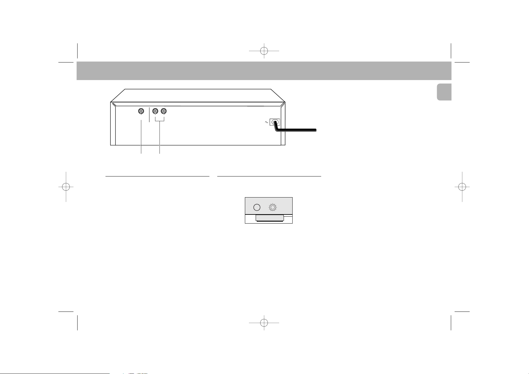
Connections
1 Digital Out
This output supplies digital signal and can therefore
only be connected to an input which is suitable for
this signal. Use here a lead with one cinch plug on
either end.
Never connect this socket to a non-digital input
of an amplifier, such as AUX, CD, TAPE, PHONO
etc!
2 Analog Out
For the connecting cable to the amplifier.
• Insert a red plug into the ‘R’ socket and the
other plug into the ‘L’ socket.
• Insert the two other plugs into the corresponding
sockets of the CD or AUX input of your amplifier.
You can also use the TUNER or TAPE IN connection,
but never the PHONO input!
Connecting Headphones
• Connect headphones with a 6.3 mm jack plug to the
PHONES socket.
• The sound level is adjusted with the LEVEL control.
Note:
– The volume control on the remote control must not be
at the minimum level.
PHONES
LEVEL
MAX
MIN
5
English
INSTALLATION
CDC775/22-Eng 6/15/00 1:37 PM Page 5
COAXIAL
RL
ANALOG
DIGITAL
OUTPUT
OUT
21
 Loading...