

Philips BYX90G Datasheet
DISCRETE SEMICONDUCTORS
DATA SH EET
ook, halfpage
M3D181
BYX90G
High-voltage soft-recovery
controlled avalanche rectifier
Product specification
Supersedes data of June 1996
1996 Sep 26

Philips Semiconductors Product specification
High-voltage soft-recovery
controlled avalanche rectifier
FEATURES
• Glass passivated
• High maximum operating
temperature
• Low leakage current
• Excellent stability
• Soft-recovery switching
characteristics
• Guaranteed avalanche energy
absorption capability.
APPLICATIONS
• High-voltage rectification at high
frequencies
• Sub-component for very high
voltage rectifiers, for example, in
X-ray and radar equipment.
DESCRIPTION
Rugged glass package, using a high
temperature alloyed construction.
This package is hermetically sealed
and fatigue free as coefficients of
expansion of all used parts are
matched.
The package is designed to be used
in an insulating medium such as
resin, oil or SF6 gas.
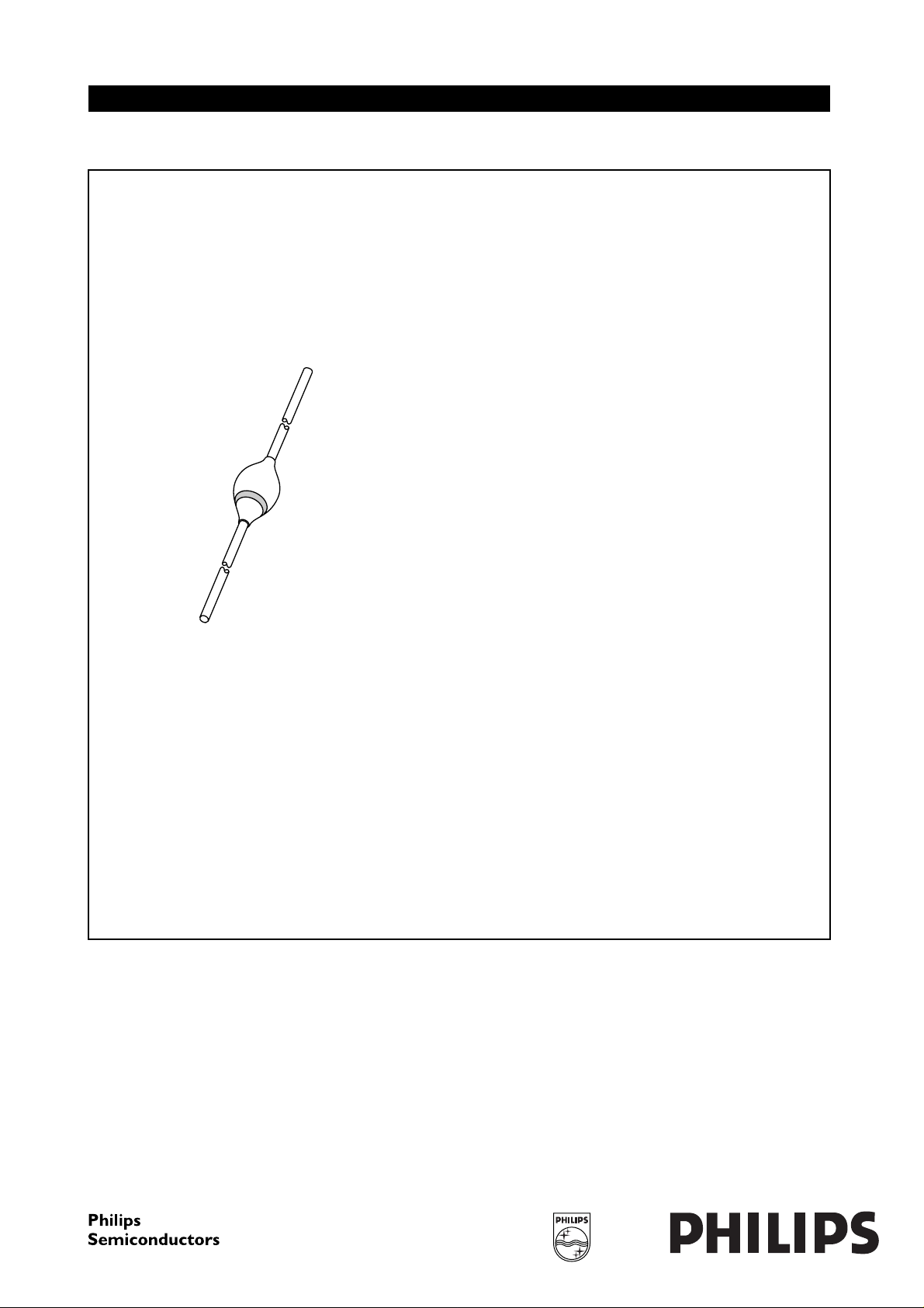
handbook, halfpage
The cathode is marked by a black band on the body.
Fig.1 Simplified outline (SOD83A) and symbol.
BYX90G
ak
MSA480
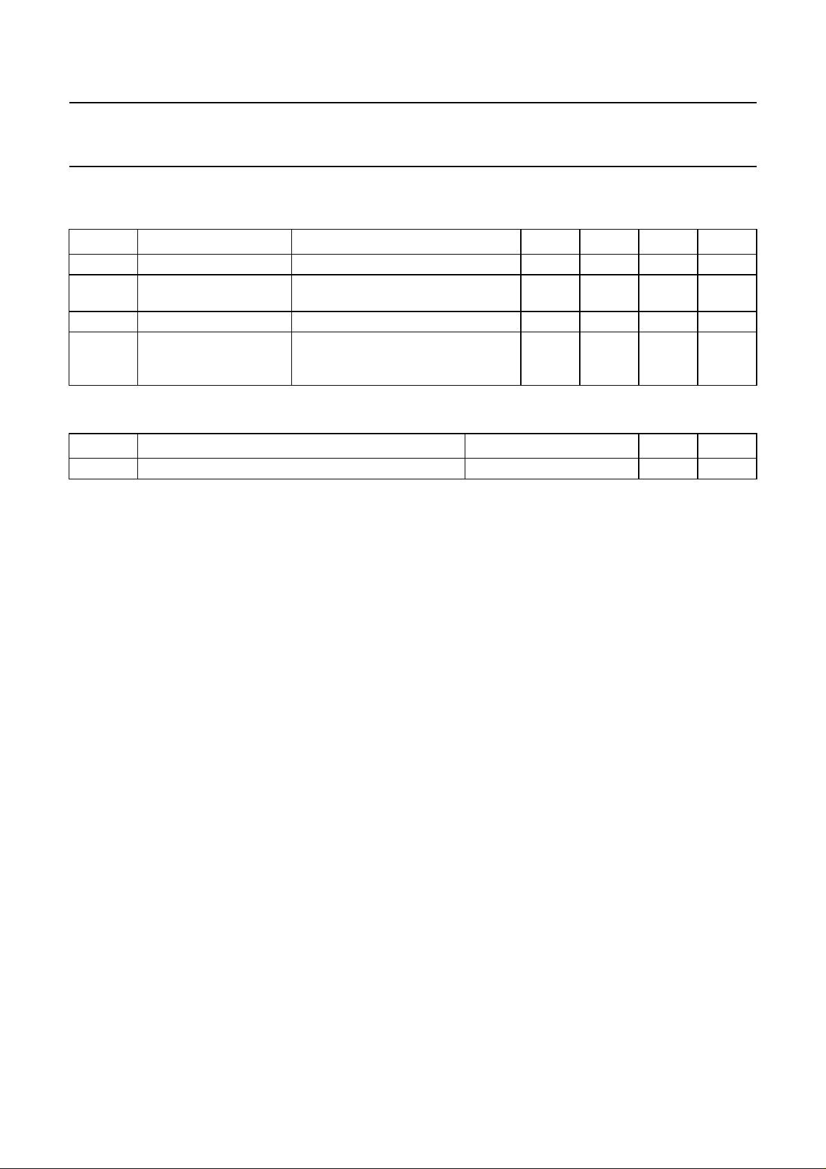
LIMITING VALUES
In accordance with the Absolute Maximum Rating System (IEC 134).
SYMBOL PARAMETER CONDITIONS MIN. MAX. UNIT
V
RRM
V
RWM
I
F(AV)
repetitive peak reverse voltage − 7.5 kV
crest working reverse voltage − 6kV
average forward current averaged over any 20 ms period;
T
=45°C; see Fig.2;
oil
− 550 mA
see also Fig.3
I
FRM
I
FSM
repetitive peak forward current − 5A
non-repetitive peak forward current t = 10 ms half sinewave; Tj=T
prior to surge; VR=V
RWMmax
;
j max
− 20 A
see Fig.4
P
RSM
T
stg
T
j
non-repetitive peak reverse power
dissipation
t=10µs; triangular pulse;
Tj=T
prior to surge
j max
− 5kW
storage temperature −65 +165 °C
junction temperature −65 +165 °C
1996 Sep 26 2
Philips Semiconductors Product specification
High-voltage soft-recovery
BYX90G
controlled avalanche rectifier
ELECTRICAL CHARACTERISTICS
T
=25°C; unless otherwise specified.
j
SYMBOL PARAMETER CONDITIONS MIN. TYP. MAX. UNIT
V
F
V
(BR)R
I
R
t
rr
THERMAL CHARACTERISTICS
SYMBOL PARAMETER CONDITIONS VALUE UNIT
R
th j-o
Note
1. For more information please refer to the
forward voltage IF= 2 A; see Fig.5 −−14.5 V
reverse avalanche
IR= 0.1 mA 8 −−kV
breakdown voltage
reverse current VR=V
RWMmax
reverse recovery time when switched from IF= 0.5 A to
; Tj=T
j max
−−50 µA
−−350 ns
IR= 1 A; measured at IR= 0.25 A;
see Fig.7
thermal resistance from junction to oil note 1; see also Fig.6 20 K/W
“General Part of associated Handbook”
.
1996 Sep 26 3
 Loading...