

Philips BY559-1500 Datasheet
Philips Semiconductors Objective specification
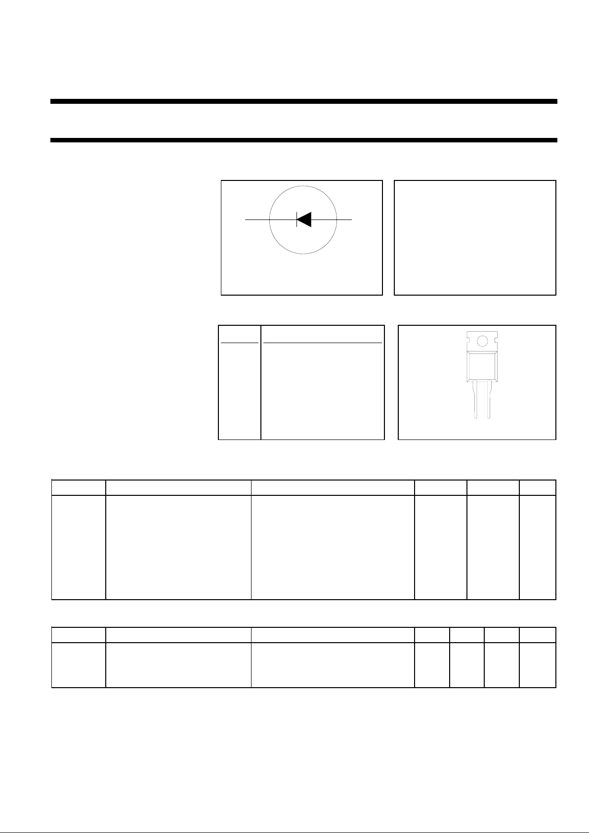
Rectifier diode BY559-1500
fast, high-voltage
FEATURES SYMBOL QUICK REFERENCE DATA
• Low forward volt drop VR = 1500 V
• Low forward recovery voltage
• Fast switching VF ≤ 1.2 V
• Soft recovery characteristic
• High thermal cycling performance Vfr ≤ 14 V
• Low thermal resistance
tfr ≤ 250 ns
I
F(AV)
= 10 A
I
FSM
≤ 100 A
GENERAL DESCRIPTION PINNING SOD59 (TO220AC)
Glass-passivated double diffused PIN DESCRIPTION
rectifierdiode featuringfastforward
recovery and low forward recovery 1 cathode
voltage. The device is intended for
usein multi-sync monitorhorizontal 2 anode
deflection circuits with maximum
scan rates from82 kHz to120 kHz. tab cathode
The BY559 series is supplied in the
conventional leaded SOD59
(TO220AC) package.
LIMITING VALUES
Limiting values in accordance with the Absolute Maximum System (IEC 134).
SYMBOL PARAMETER CONDITIONS MIN. MAX. UNIT
V
RRM
Peak repetitive reverse voltage - 1500 V
V
RWM
Crest working reverse voltage - 1300 V
I
FWM
Peak working forward current f = 120 kHz; - 10 A
I
FRM
Peak repetitive forward current t = 100 µs - 150 A
I
FSM
Peak non-repetitive forward t = 10 ms - 180 A
current t = 8.3 ms - 200 A
sinusoidal; Tj = 150 ˚C prior to
surge; with reapplied V
RWM(max)
T
stg
Storage temperature -40 150 ˚C
T
j
Operating junction temperature - 150 ˚C
THERMAL RESISTANCES
SYMBOL PARAMETER CONDITIONS MIN. TYP. MAX. UNIT
R
th j-mb
Thermal resistance junction to - - 1.0 K/W
mounting base
R
th j-a
Thermal resistance junction to in free air - 60 - K/W
ambient
k a
12
1
tab
2
September 1998 1 Rev 1.100

Philips Semiconductors Objective specification
Rectifier diode BY559-1500
fast, high-voltage
STATIC CHARACTERISTICS
Tj = 25 ˚C unless otherwise stated
SYMBOL PARAMETER CONDITIONS MIN. TYP. MAX. UNIT
V
F
Forward voltage IF = 10 A - 1.0 1.25 V
IF = 10 A; Tj = 125 ˚C - 0.79 0.9 V
I
R
Reverse current VR = V
RWMmax
- - 0.5 mA
VR = V
RWMmax
; Tj = 125 ˚C - - 2.0 mA
DYNAMIC CHARACTERISTICS
Tj = 25 ˚C unless otherwise stated
SYMBOL PARAMETER CONDITIONS MIN. TYP. MAX. UNIT
V
fr
Forward recovery voltage IF = 10 A; dIF/dt = 50 A/µs-711V
t
fr
Forward recovery time IF = 10 A; dIF/dt = 50 A/µs; VF = 5 V - 250 350 ns
IF = 10 A; dIF/dt = 50 A/µs; VF = 2 V - 450 600 ns
t
rr
Reverse recovery time IF = 1 A; -dIF/dt = 50 A/µs; VR ≥ 30 V - 0.75 1.0 µs
Q
s
Reverse recovery charge IF = 2 A; -dIF/dt = 20 A/µs; VR ≥ 30 V - 4.0 5.0 µC
September 1998 2 Rev 1.100
 Loading...