

Philips BY459DX-1500S Datasheet
Philips Semiconductors Preliminary specification
Damper diode BY459DX-1500, BY459DX-1500S
fast, high-voltage
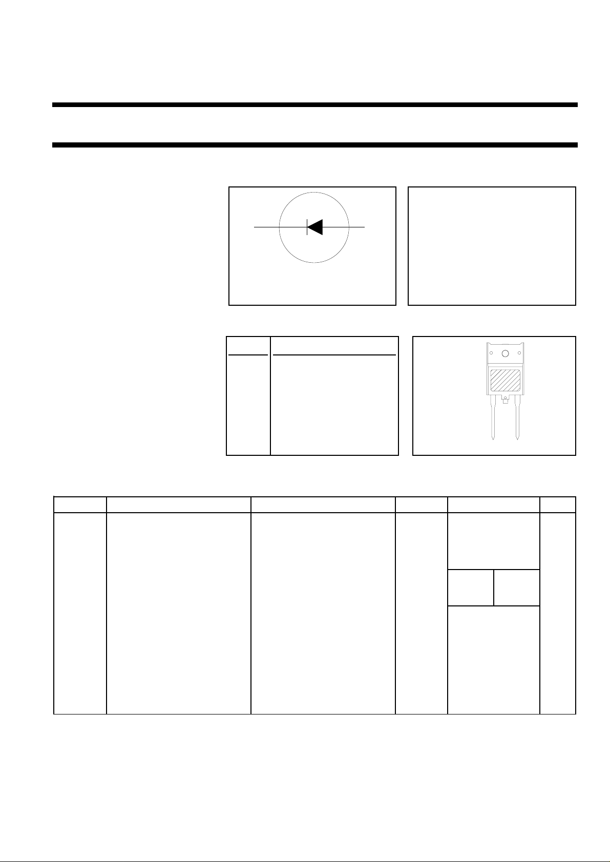
FEATURES SYMBOL QUICK REFERENCE DATA
• Low forward volt drop VR = 1500 V
• Fast switching
• Soft recovery characteristic VF ≤ 1.2 V / 1.25 V
• High thermal cycling performance
• Isolated mounting tab I
GENERAL DESCRIPTION PINNING SOD117
k a
12
= 12 A (f = 48 kHz)
F(peak)
I
= 10 A (f = 82 kHz)
F(peak)
I
trr ≤ 350 ns / 220 ns
≤ 100 A
FSM
Glass-passivated double diffused PIN DESCRIPTION
case
rectifierdiodefeaturingfast forward
recovery and low forward recovery 1 cathode
voltage. The device is intended for
use in HDTV receivers and 2 anode
multi-sync monitor horizontal
deflection circuits. tab isolated
The BY459DX series is supplied in
the conventional leaded SOD117
12
package.
LIMITING VALUES
Limiting values in accordance with the Absolute Maximum System (IEC 134).
SYMBOL PARAMETER CONDITIONS MIN. MAX. UNIT
V
RSM
V
RRM
V
RWM
I
F(peak)
I
FRM
I
F(RMS)
I
FSM
T
stg
T
j
Peak non repetitive reverse - 1500 V
voltage
Peak repetitive reverse - 1500 V
voltage
Crest working reverse voltage - 1300 V
-1500 -1500S
Peak working forward current f = 48 kHz; - 12 - A
f = 82 kHz; - - 10 A
Peak repetitive forward t = 100 µs - 100 A
current
RMS forward current - 30 A
Peak non-repetitive forward t = 10 ms - 100 A
current t = 8.3 ms - 110 A
sinusoidal; Tj = 150 ˚C prior to
Storage temperature -40 150 ˚C
surge; with reapplied V
RWM(max)
Operating junction - 150 ˚C
temperature
August 1998 1 Rev 1.100

Philips Semiconductors Preliminary specification
Damper diode BY459DX-1500, BY459DX-1500S
fast, high-voltage
ISOLATION LIMITING VALUE & CHARACTERISTIC
Ths = 25 ˚C unless otherwise specified
SYMBOL PARAMETER CONDITIONS MIN. TYP. MAX. UNIT
V
isol
C
isol
THERMAL RESISTANCES
SYMBOL PARAMETER CONDITIONS MIN. TYP. MAX. UNIT
R
th j-hs
R
th j-a
STATIC CHARACTERISTICS
Tj = 25 ˚C unless otherwise stated
SYMBOL PARAMETER CONDITIONS TYP. MAX. UNIT
V
F
I
R
R.M.S. isolation voltage from f = 50-60 Hz; sinusoidal - 2500 V
both terminals to external waveform;
heatsink R.H. ≤ 65% ; clean and dustfree
Capacitance from both terminals f = 1 MHz - 10 - pF
to external heatsink
Thermal resistance junction to with heatsink compound - - 3.6 K/W
heatsink without heatsink compound - - 4.5 K/W
Thermal resistance junction to in free air. - 35 - K/W
ambient
BY459DX- 1500 1500S 1500 1500S
Forward voltage IF = 6.5 A 0.95 1.05 1.30 1.35 V
IF = 6.5 A; Tj = 125 ˚C 0.85 0.95 1.20 1.25 V
Reverse current VR = 1300 V - 250 - 250 µA
VR = 1300 V; Tj = 125 ˚C - 1 - 1 mA
DYNAMIC CHARACTERISTICS
Tj = 25 ˚C unless otherwise stated
SYMBOL PARAMETER CONDITIONS TYP. MAX. UNIT
BY459DX- 1500 1500S 1500 1500S
t
rr
Q
s
V
fr
t
fr
Reverse recovery time IF = 1 A, VR ≥ 30 V; 0.25 0.17 0.35 0.22 µs
Reverse recovery charge IF = 2 A, -dIF/dt = 20 A/µs 2.0 0.70 3.0 0.95 µC
Peak forward recovery voltage IF = 6.5A, dIF/dt = 50A/µs 8.0 11.0 14.0 19.0 V
Forward recovery time IF = 6.5A, dIF/dt = 50A/µs 170 200 250 300 ns
August 1998 2 Rev 1.100
 Loading...