

Philips BY228-50, BY228-40, BY228-33, BY228-24, BY228-23 Datasheet
...
DATA SH EET
Product specification
Supersedes data of May 1996
1996 Sep 26
DISCRETE SEMICONDUCTORS
BY228
Damper diode
handbook, 2 columns
M3D118
1996 Sep 26 2
Philips Semiconductors Product specification
Damper diode BY228
FEATURES
• Glass passivated
• High maximum operating
temperature
• Low leakage current
• Excellent stability
• Available in ammo-pack
• Also available with preformed leads
for easy insertion.
APPLICATIONS
• Damper diode in high frequency
horizontal deflection circuits up to
16 kHz.
DESCRIPTION
Rugged glass package, using a high
temperature alloyed construction.
This package is hermetically sealed
and fatigue free as coefficients of
expansion of all used parts are
matched.
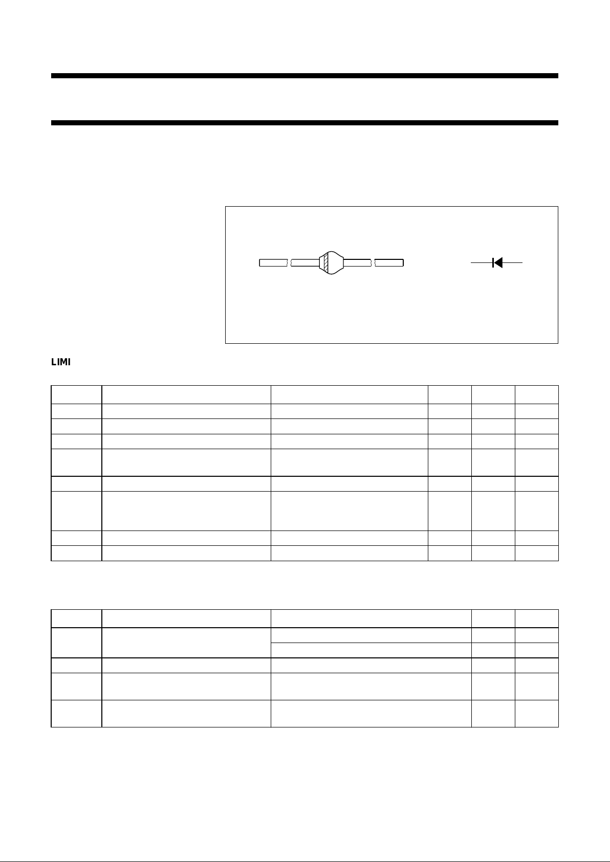
Fig.1 Simplified outline (SOD64) and symbol.
2/3 page (Datasheet)
MAM104
ka
LIMITING VALUES
In accordance with the Absolute Maximum Rating System (IEC 134).
ELECTRICAL CHARACTERISTICS
T
j
=25°C; unless otherwise specified.
SYMBOL PARAMETER CONDITIONS MIN. MAX. UNIT
V
RSM
non-repetitive peak reverse voltage − 1650 V
V
RRM
repetitive peak reverse voltage − 1650 V
V
R
continuous reverse voltage − 1500 V
I
FWM
working peak forward current T
amb
=75°C; PCB mounting (see
Fig.4); see Fig.2
− 5A
I
FRM
repetitive peak forward current − 10 A
I
FSM
non-repetitive peak forward current t = 10 ms half sinewave;
Tj=T
j max
prior to surge;
VR=V
RRMmax
− 50 A
T
stg
storage temperature −65 +175 °C
T
j
junction temperature −65 +150 °C
SYMBOL PARAMETER CONDITIONS MAX. UNIT
V
F
forward voltage IF= 5 A; Tj=T
j max
; see Fig.3 1.4 V
I
F
= 5 A; see Fig.3 1.5 V
I
R
reverse current VR=V
Rmax
; Tj= 150 °C 150 µA
t
rr
reverse recovery time when switched from IF= 0.5 A to IR=1A;
measured at IR= 0.25 A; see Fig.6
1 µs
t
fr
forward recovery time when switched to IF= 5 A in 50 ns;
Tj=T
j max
; Fig.7
1 µs

1996 Sep 26 3
Philips Semiconductors Product specification
Damper diode BY228
THERMAL CHARACTERISTICS
Note
1. Device mounted on an epoxy-glass printed-circuit board, 1.5 mm thick; thickness of Cu-layer ≥40 µm, see Fig.4.
For more information please refer to the
“General Part of associated Handbook”
.
SYMBOL PARAMETER CONDITIONS VALUE UNIT
R
th j-tp
thermal resistance from junction to tie-point lead length = 10 mm 25 K/W
R
th j-a
thermal resistance from junction to ambient note 1 75 K/W
mounted as shown in Fig.5 40 K/W
 Loading...