

Page 1
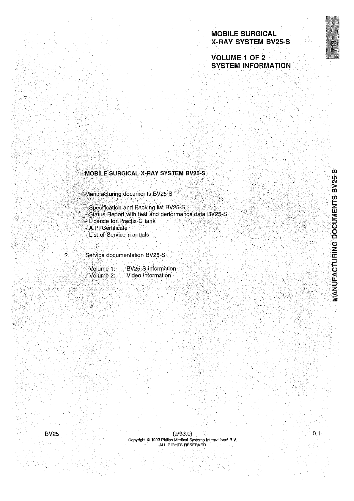
MOBILE
X-RAY
SURGICAL
SYSTEM
BV25-S
(MOBILE
2.
Licence.
Service
SURGICAL
ical
Report
for:Practix-
‘Certificate
tof
Service:
documentation
ion
and.
:
X-RAY
Packing
with test
GC
tank
-
manuals
BV25-S
Video
-
BV25-S
information
information“
SYSTEM
list
BV25-
s
and
performance « data
:
..:
VOLUME
SYSTEM
BV25-5
6
-
В\25-
8
1
OF
2
INFORMATION
の
10
N
>
m
o
-E
z
L
=
5
“O
“©
a
G
=
E
5
p
o
e
jn
5
=
<
=
BV25
©!
Copyright © 1993
(a/93.0)
Philips
ALL
RIGHTS
Medical
RESERVED.
Systems
Intemational
В.М.
0.1
Page 2

Page 3

MOBILE
SYSTEM
SURGICAL
BV25-S
X-RAY
¿FILING
“This
Service
-
Mebile
INSTRUCTIONS
manual
should
documentation
Surgical
X-ray
be
filed
for.
system
in
the
the
BV25-8.
set
BV25-S
of
SYSTEM
X-RAY
SURGICAL
MOBILE
BV25
Copyright O 1993
Philips
ALL
RIGHTS
(a/93.0)
Medical
Systems
RESERVED
Intematlonat
'
B.V.
0.5
Page 4

Page 5
P
Pk
SES
area
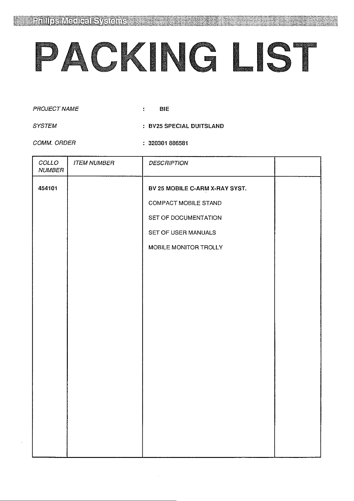
PROJECT
SYSTEM
COMM.
COLLO
NUMBER
454101
NAME
ORDER
ITEM
NUMBER
:
BIE
:
BV25
SPECIAL
:
320301
DESCRIPTION
BV
25
MOBILE
COMPACT
SET
OF
SET
OF
MOBILE
DUITSLAND
886581
C-ARM
MOBILE
DOCUMENTATION
USER
MONITOR
STAND
MANUALS
TROLLY
X-RAY
SYST.
Page 6

Page 7

SYSTEM
KIND
ORDER-DELIVERY-SHEET
:
/ /
/
/
/
PROJECT-DEST:
COUNTRY
HOSPITAL
CUST.
ORDER
SHOPORDER
PROJECT-NUMBER:
CORRESPONDENT
LINE
NO
1010
ITEM
989600022651
0001
2001
2002
2003
2004
2005
0002
BIE
:
GERMANY
O:
320301
:
SBO
CE00587
9896
000
:
6000
DIS
NO
MMC1001
989600006451
989600006471
980775300001
984910000201
980772102001
989601010231
UPDATED
886581
22651
BASELMA
QIY
1
INCLUDING
ORDER-KIND : OL
SCREENER:
TTEM
DESCRIPTION
BV25
SPECIAL
1
BV25
1
UNIVERSAL
1
SUPPL.BV25
1
HMR17S
1
MOUNTINGSET
1
DIGITAL
1
THERMAL
CHANGE
6000
SYSTEM
TV
SCOPOFIX
PRINTER
NBR:
DIS
LODEWYK
GERMANY
PART BV25
TEC
50HZ
MON.ROT.50HZ
ONE
17"
MDP
UP-910
LOT-NO
0000042105
XTV8S
XTV8S
MON.
CDD
220695
キーーーーーーーーーーーーーーーーーーーーーーーーーーーーーーーーーーーーーーーーーーーーーーーーーーーーーーーーーーーーーーーーーーーーーーーーーーーーー 一 +
1
COS-ORDER-NBR:
0000060505
PRINIDATE:
08/06/95
PAGE
NBR:
END
!
Page 8

Page 9
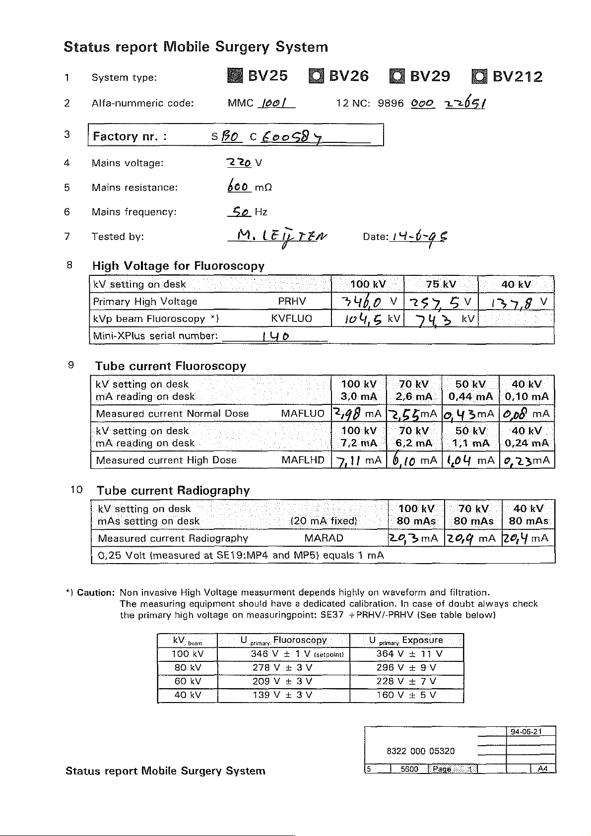
Status
1
2
3 | Factory
4
5
6
7
8
report
System
Alfa-nummeric
Mains
Mains
Mains
Tested
High
kV
Primary
kVp
Mini-XPlus
type:
voltage:
resistance:
frequency:
by:
Voltage
setting
High
beam
Mobile
code:
nr.
:
for
on
desk
Voltage
Fluoroscopy
serial
number:
Surgery
1BV25
MMC
67890
Fluoroscopy
*)
cEeoS94
220
60
So
M,
_/00/
V
ma
Hz
LE
KVFLUO
{uo
System
ElBv26
IL
KEM
PRHV
12
a,
lo
NC:
Date:
100.kV
nr
4,
Ew
9896
19-64
vlasy
BV29
600
7
75
ya
ユ っ 6
e
kV
5V|
kV
Я
ちら
/
8В\212
40
kV
1397, 9 V
9
Tube
kV setting
mAreading
Measured
kV
má
Measured
10
Tube
kV
mAs:setting.on
Measured
0,25
*}
Caution:
current
on
on
current
setting:on
reading
on
current
current
setting
Non
The
the
Volt
invasive
measuring
primary
on
current
(measured
Fluoroscopy
desk
desk
Normal
desk
desk
High
Dose
Radiography
desk
desk
Radiography
at
SE19:MP4
High
Voltage
equipment
high
voltage
KV.
beam
100
kV
80 kV
60
kV
40
kv
Dose
measurment
should
on
measuringpoint:
U
mary:
346 V + 1 V
278V
209V
139V
MAFLUO
MAFLHD | 9,1}
(20:mA
and
MP5)
depends
have a dedicated
FIUOTOSCOPY
ょ
3V
ょ
3V
+
3V
2,48
fixed)
MARAD
equals 1 mA
highly
SE37
Getpoinn
100
kV
3,0 mA: | 2;6mA:|0;44
mA
100
kV
7,2:mA
mA
on
calibration.
+PRHV/-PRHV
70.kV
Te と ちあ
70-kV
6,2
6,10
100:
80.mAs. | 80
た
らち
waveform
In
U
primary,
EXposure
364 V +
296V
228V + 7V
160V
19V
+ 5V
mA
mA
mA
kv.
mA
case
(See
11
| y 3mA
(20,
and
of
table
V
50
kV
mA
50.kV
4,1
mA:
toy
mA | みて ぅ mA
70:KV.
mAs | 80
mA 2 みり
filtration.
doubt
always
below)
40
kV
(0,10.
mA
008
40
0.24
mA
kV.
mA
40
kV
mAs
mA
check
Status
report
Mobile
Surgery
System
8322
5800
000
94-06-21
05320
Page 10

Page 11

11
12
13
High
Exposure
Voltage
kV
setting: on
Primary
kV:setting
kVp
Mini-XPlus
mÂs
Exposure
Beam
Deviation
Fluoroscopy
Fluoroscopy
Fluoroscopy
High
beam
setting:on
Time
Alignment
for
Radiography
desk
Voltage
on
desk
Radiography
serial
number:
Time
Radiography
desk
Fluoroscopy / Radiography
*)
{20
FO
F1
F2
Factory
PRHV
KVRAD
(Yo
mA
fixed}
Cfluo
Ч
nr.
:
100:kV
3691
100.kV
105,
пт
mm
mm
Y
2
mAs
{ve
P:+:0
(a
mm]
mm
mm mm
S
kv
ms
Bo
Vİ
li
C
75
2
80 КУ
a
20
(1,00
R:+:S
E60 2 グッ
kV
78XVİ
19
mm
mm
к
mAs
P+:0Q
sl
av»
40
kV
1558
60 kV
5 q q
80
mAs
νσο
ТР
+R
+S
V
kv
s
mm
mm
mm
Deviation
Radiography
FO = Largest
14
Visible
IF
Horizontal
Vertical
FO = Largest
*)
Caution:
mode
Non
Measuring
primary
Area
invasive
high
Il
format
ll
format
High
equipment
voltage
F1
and
F1
and
Voltage
measurment
should
on
measuringpoint:
Crad
7
F2
F2
have a dedicated
mm
not
applicable
not
applicable
depends
SE37
[리의
to
for
FO
LU
142
for
highly
calibration.
+PRHV/-PRHV
ПА
mm
BV25/26
BV25/26
on
tt
mm
mm
waveform
In
case
of
(See
table
mm
F1
and
filtration.
doubt
page
ГРОТ
R
mm
mm
always
1)
+
А+
F2
The
check
$]
mm
mm
mm
the
Status
report
Mobile
Surgery
System
8322
000
05320
Page 12

Page 13
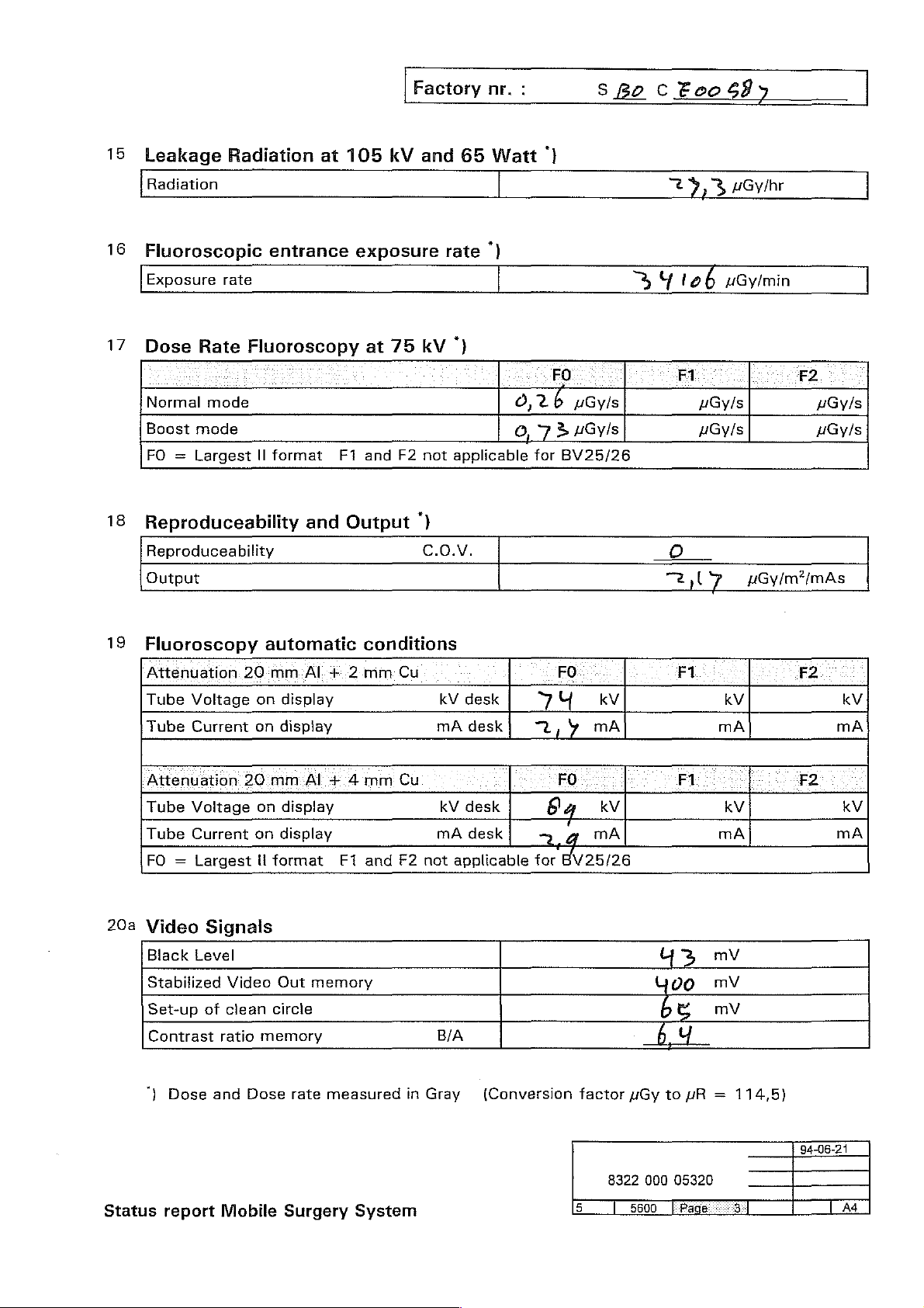
15
Leakage
Radiation
16
Fluoroscopic
Exposure
17
Dose
Normal
Boost
FO = Largest
Radiation
rate
Rate
mode
Fluoroscopy
mode
entrance
ll
format
at
105
F1
Factory
kV
exposure
at
75 kV
and
F2
and
rate
')
not
applicable
nr.
65
Watt
")
:
0,26
07
for
S
Be
C
|
25,3
3
Y
FO
AGyls AGyls
3
/Gy/S
BV25/26
€eo
106
F1
uGy/s
683
uGylhr
uGy/min
F2
uGy/s
μαγ/ς
18
Reproduceability
Reproduceability
Output
19
Fluoroscopy
Attenuation:
Tube
20a
Voltage
Tube
Current
Attenuation
Tube
Voltage
Tube
Current
FO = Largest
Video
Black
Stabilized
Set-up
Contrast
Signals
Level
Video
of
clean
ratio
automatic
20
mm-Al-+:2-mm
on
display
on
display
20
mm:Al
on
display
on
display
il
format
Out
circle
memory
and
'+.4
memory
Output
conditions
Cu FO
mm
Cu
Е1
and
F2
)
σ.ο.ν.
kV
desk
mA
desk
kV
desk
mA
desk
not
applicable
BIA
O
7
y
kV kV
그,
y
mA mA
FO
ба
っ
for
kV kV
a
mA mA
BV25/26
“2,07
F1
F1
Uz
Yoo
6
と
6
Ч
uGy/m?”/mAs
mv
mV
mV
F2
kV
mA
F2
kV
mA
‘}
Status
Dose
report
and
Mobile
Dose
rate
measured
Surgery
System
in
Gray
(Conversion
factor
8322
uGy
000
5600
to
uR = 114,5)
05320
94-06-21
Page 14

Page 15
Factory
nr.
:
sBo
ο
Ecos87
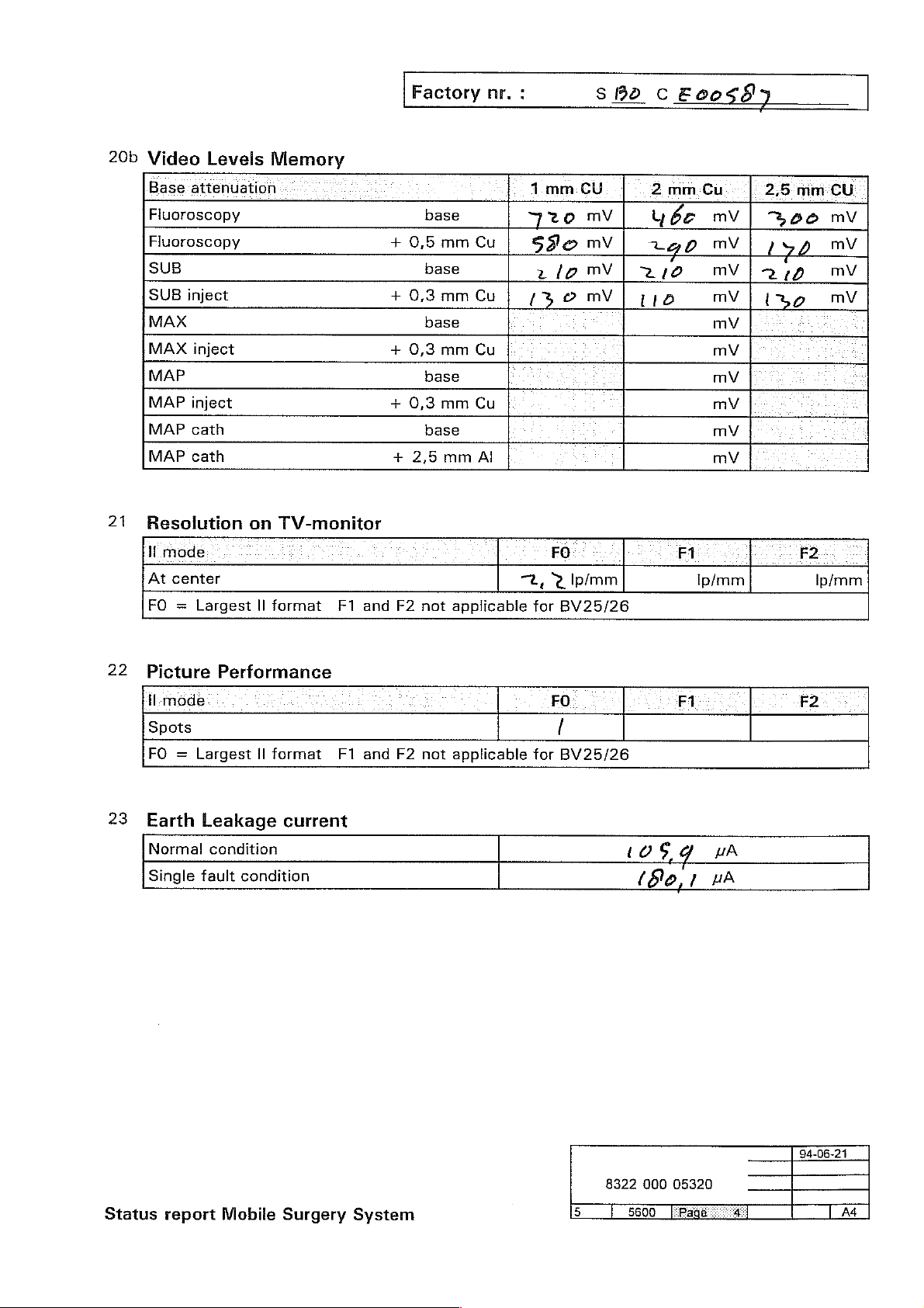
Video
20b
Base.
Fluoroscopy
Fluoroscopy
SUB
SUB
MAX
MAX
MAP
MAP
MAP
MAP
21
Resolution
ll
At
FO = Largest
Levels
attenuation
inject
inject
inject
cath
cath
mode
center
Memory
on
TV-monitor
Il
format
F1
and
+
+
+
+
+
F2
base
0,5
base
0,3
base
0,3
base
0,3
base
2,5
not
Cu
mm
Cu
mm
Cu
mm
Cu
mm
Al
mm
applicable
CU
mm
1
2
FO
BV25/26
mV
mV
WY|
|
м\
720
São
2lp
[5
TL, © Ip/mm
for
2
Ube
20
2/0
116
mm
7
F1
Cu
mV
mV
MV
mV
mV
mV
mV
mV
mV
mV
ip/mm
mm'CU
2,5
3060
|
isd
č
2/9
zo
|
mV
mV
MV
mV
F2
Ip/mm
22
Picture
i-mode
Spots
FO = Largest
23
Earth
Normal
Single
Performance
Il
format
Leakage
condition
fault
condition
F1
current
and
F2
not
applicable
for
FO
/
BV25/26
(OS
EN
F1
Gg
uA
LA
F2
Status
report
Mobile
Surgery
System
8322
000
05320
R
Page 16

Page 17

24
Earth
Trolley
25
26
Resistance
{container
X-Ray
C-arm
Monitor
Stand
Reference
Installed
Release
tank
covers
covers
number
Installed
System
Second
Image
Video
Video
Video
Image
Angio
Video
Video
Remote
Laser
Printer
type
Monitor
Storige
Data
Hard
Hard
Storage
Extension
Memory
Memory
Aligment
Sony
point:
Software
Options
Extension
Unit
Copy
Copy
190 + Mosaic
32
128
Control
Tool
UP910
earth
for
Unit
Unit
images
terminal
release
BV25
34
1
1/4
images
Factory
of
mains
images
plug
MMC
MMC
MMC
MMC
MMC
MMC
MMC
MMC
MMC
MMC
MMC
MMC
nr.:
1031
1041
1051
1061
1081
1112
1122
1131
1141
1191
1201
1211
SBo
BV25
图
Я
回
回
回
E
ES
C
Evo
tip
ize
(16
122
gs
|
io
Rel:
BV26
.—
a
到
a a
回
E G
E
a
回
Я
İY
ma
то
MQ
ma
mQ
ma
BV29
回
回
回
E
E
B
回
BV212
回
回
a
G
B
a
a
回
THIS
EXACTING
SHOULD
Status
EQUIPMENT
report
METHODS
ANY
COMPLAINT
Mobile
HAS
BEEN
AND
Surgery
INSPECTED
WAS
ARISE
System
FOUND
PLEASE
AND
TO
QUOTE
TESTED
CONFORM
SYSTEM
BY
THE
LATEST
TO
SPECIFICATION.
SERIAL
8322
000
5600
NO.
05320
ER:
AND
MOST
cE20.59
y
Page 18

Page 19
SERVICE
MANUAL-SYSTEM
Mobile
Surgical
BV25-S
9896
000
X-ray
06451
System
BV25
This
manual
It
is
used
Copyright C "93
contains
for
TV
Copyright © 1993
information
fluoroscopy
in
operating
PHILIPS
PRINTED
Philips
ALL
on
the
with
image
and
emergency
MEDICAL
IN
THE
(a/93.0)
Medical
RIGHTS
Systems
RESERVED
Mobile
Surgical
intensifier
rooms.
SYSTEMS
NETHERLANDS
International
X-ray
System
and
for
radiography
INTERNATIONAL
B.V.
BV25-S.
B.V.
0.6
Page 20

Page 21
BV25
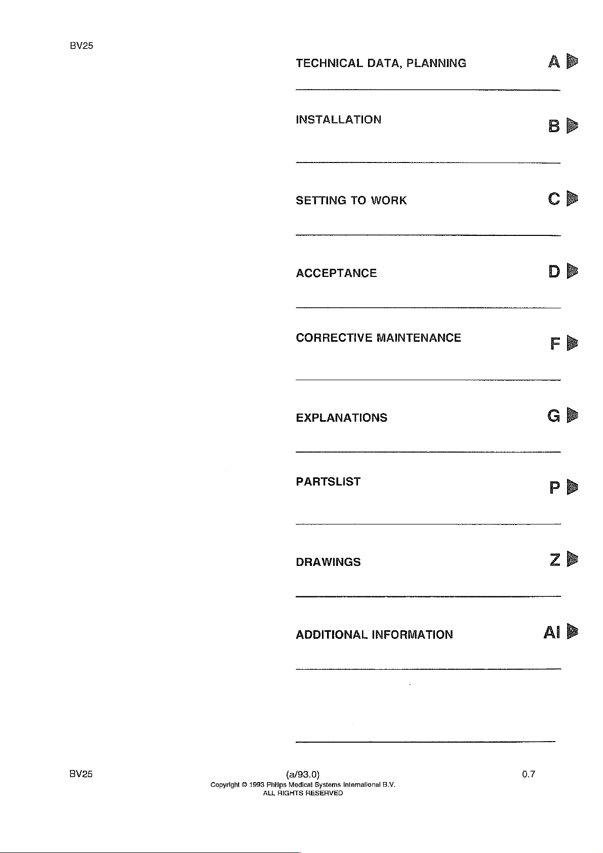
TECHNICAL
DATA,
INSTALLATION
SETTING
TO
WORK
АССЕРТАМСЕ
CORRECTIVE
MAINTENANCE
PLANNING
A
B
BB
СВ
ОВ
FB
EXPLANATIONS
PARTSLIST
DRAWINGS
ADDITIONAL
INFORMATION
СВ
PD
zb
Al
B
BV25
Copyright © 1993
(a/93.0)
Philips
ALL
RIGHTS
Medical
RESERVED
Systems
Intemational
8.V.
0.7
Page 22

Page 23

BV25
SERVICE
MOBILE
9896
LIST
OF
0.1
0.2
0.3
0.4
0.5
0.6
0.7
21
22
23
A-1
A-2
A-3
A-4
Α-5
A-6
A-7
A-8
A-9
A-10
A-11
A-12
AZ-1
AZ-2
B-1
B-2
B-3
B-4
B-5
B-6
B-7
MANUAL-SYSTEM
SURGICAL
000
06451
PAGES
AND
X-RAY
DRAWINGS
SYSTEM
(a/93.0)
(91.0)
(91.0)
(a/93.0)
(a/93.0)
(a/93.0)
(a/93.0)
(a/93.0)
(a/93.0)
(a/93.0)
(93.0)E
(a/93.0)E
(a/93.0)E
(91.0)E
(a/93.0)E
(a/93.0)E
(91.0)E
(a/93.0)E
(91.0)E
(91.0)E
(a/93.0)E
(93.0)E
(91.0)E
(91.0)E
(a/93.0)E
(a/93.0)E
(91.0)E
(91.0)E
(91.0)E
(91.0)E
(92.0)E
BV25-S
C-2
C-3
C-4
C-5
C-7
C-8
C-9
C-10
C-11
С-12
С-13
C-14
С-15
C-16
С-17
C-18
C-19
CZ-1
CZ-2
(a/93.0)E
(91.0)E
(91.0)E
(91.0)E
(a/93.0)E
(91.0)E
(91.0)E
(91.0)E
(91.0)E
(91.0)E
(91.0)E
(91.0)E
(91.0)E
(91.0)E
(a/93.0)E
(a/93.0)E
(a/93.0)E
(a/93.0)E
(a/93.0)E
(91.0)E
(91.0)E
BV25
Copyright © 1993
(a/93.0)
Philips
Medical
ALL
RIGHTS
Systems
RESERVED
International
B.V.
2.1
Page 24

Page 25
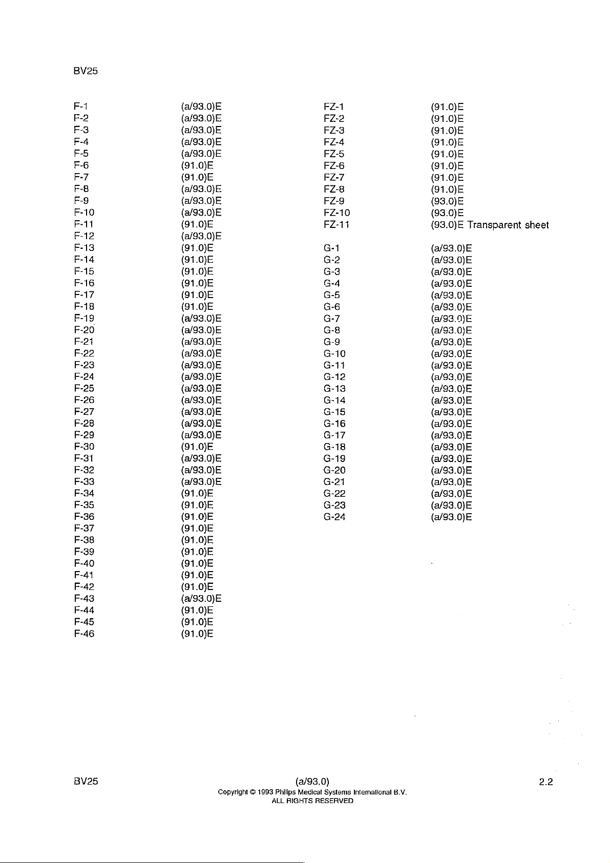
F-10
F-11
F-12
F-13
F-14
F-15
F-16
F-17
F-18
F-19
F-20
F-21
F-22
F-23
F-24
F-25
F-26
F-27
F-28
F-29
F-30
F-31
F-32
F-33
F-34
F-35
F-36
F-37
F-38
F-39
F-40
F-44
F-42
F-43
F-44
F-45
F-46
(91.0)E
(a/93.0)E
(a/93.0)E
(a/93.0)E
(91.0)E
(a/93,0)E
(91.0)E
(a/93.0)E
(a/93.0)E
(a/93.0)E
(a/93.0)E
(a/93.0)E
(91.0)E
(a/93.0)E
(a/93.0)E
(a/93.0)E
(a/93.0)E
(91.0)E
(91.0)E
(91.0)E
FZ-1
FZ-2
ΕΖ-8
FZ-4
FZ-5
FZ-6
FZ-7
FZ-8
FZ-9
FZ-10
FZ-11
G-4
G-10
G-11
G-12
G-13
G-14
G-15
G-16
G-17
G-18
G-19
G-20
G-21
G-22
G-23
G-24
(91.0)E
(91.0)E
(91.0)E
(91.0)E
(91.0)E
(91.0)E
(91.0)E
(91.0)E
(93.0)E
(93.0)E
(93.0)E
Transparent
(a/93.0)E
(a/93.0)E
(a/93.0)E
(a/93.0)E
(a/93.0)E
(a/93.0)E
(a/93.0)E
(a/93.0)E
(a/93.0)E
(a/93.0)E
(a/93.0)E
(a/93.0)E
(a/93.0)E
(a/93.0)E
(a/93.0)E
(a/93.0)E
(a/93.0)E
(a/93.0)E
(a/93.0)E
(a/93.0)E
sheet
BV25
Copyright © 1993
(a/93.0)
Philips
Medical
ALL
RIGHTS
Systems
RESERVED
International
8.V.
2.2
Page 26

Page 27
BV25
(a/93.0)
(a/93.0)
(a/93.0)
(a/93.0)
(e/93.0)
(893.0)
(93.0)
(93.0)
(93.0)
(93.0)
(93.0)
(91.0)
(91.0)
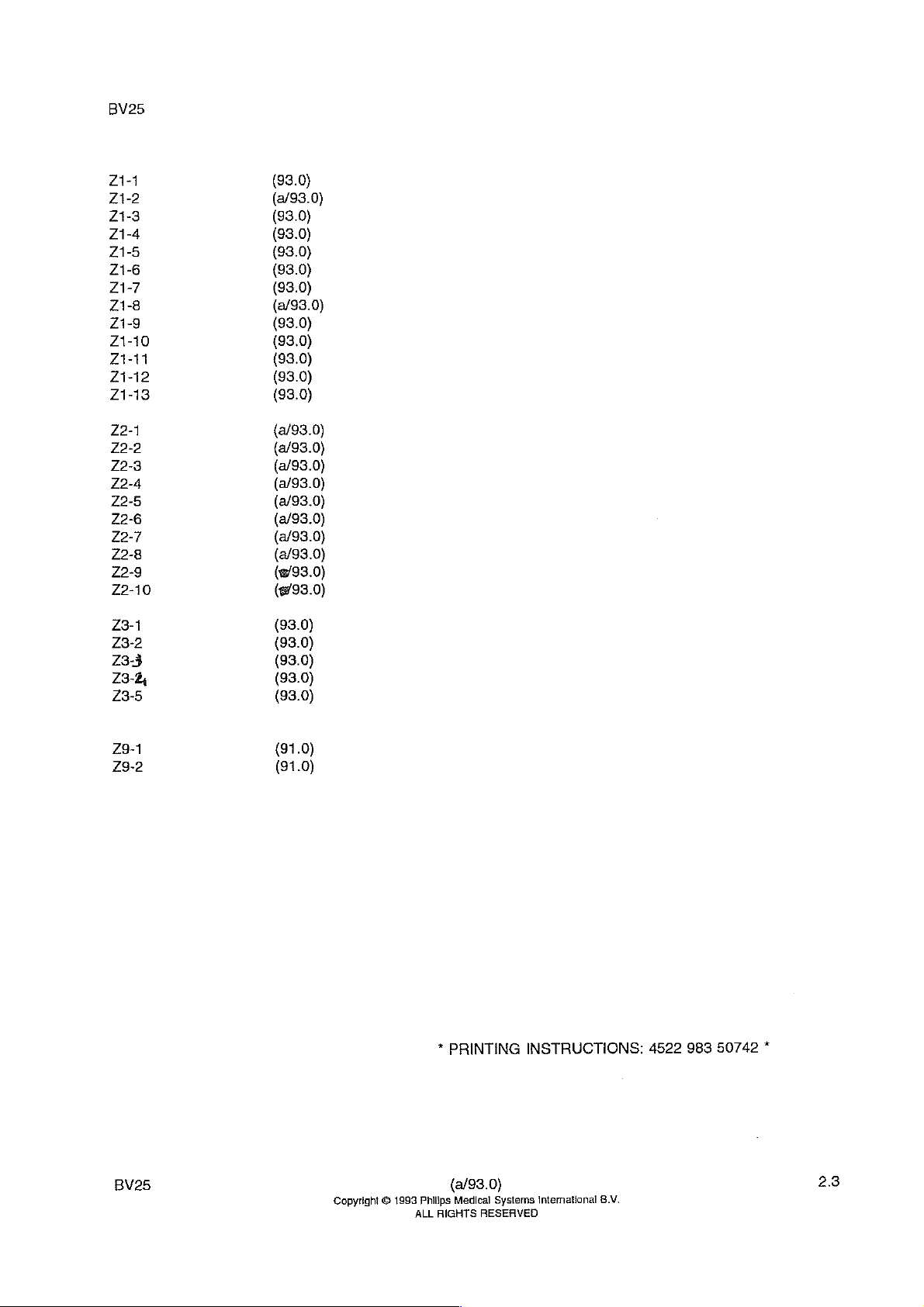
*
PRINTING
INSTRUCTIONS:
4522
983
50742
*
BV25
Copyright © 1993
(a/93.0)
Philips
ALL
RIGHTS
Medical
RESERVED
Systems
intemational
23
В.М.
Page 28

Page 29
Page 30
Section
1.
The
rooms
2.
The
BV25-S
The
3.
A
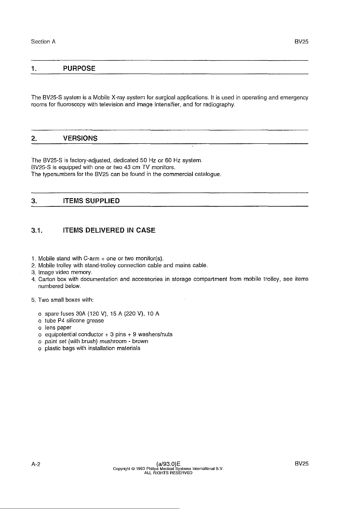
PURPOSE
BV25-S
system
for
fluoroscopy
VERSIONS
BV25-S
typenumbers
is
factory-adjusted,
is
equipped
ITEMS
is a Mobile
with
with
one
for
the
BV25
SUPPLIED
X-ray
television
dedicated
or
two
can
be
system
and
43
cm
found
for
image
50
TV
in
Hz
surgical
intensifier,
or
applications.
60
Hz
monitors.
the
commercial
and
for
system.
catalogue.
It
is
used
radiography.
in
operating
and
BV25
emergency
3.1.
.
Mobile
.
Mobile
.
Image
.
Carton
BEN
numbered
5.
Two
small
spare
tube
lens
equipotential
paint
plastic
900000
ITEMS
stand
with
trolley
with
video
memory.
box
with
below.
boxes
fuses
P4
silicone
paper
set
(with
bags
DELIVERED
C-arm + one
stand-trolley
documentation
with:
30A
(120
V),
grease
conductor
brush)
mushroom - brown
with
installation
or
connection
and
15 A (220
+ 3
pins + 9
materials
IN
CASE
two
monitor(s).
accessories
V),
washers/nuts
cable and
in
10 A
mains
storage
cable.
compartment
from
mobile
trolley,
see
items
A-2
Copyright © 1993
(a/93.0)E
Philips
Medical
ALL
RIGHTS
Systems
RESERVED
Intemational
B.V.
BV25
Page 31

BV25
6.
Set
of 5 sterilizable
Practix-C
Footswitch
Cassette
Cassette
oan
when
10.
Set
of
11.
Operator's
12.
Manufacturing
o
Status
Configuration
ο
Licence
ο
A.P.
ο ο
List
covers
tank,
and
shield
holder
IEC
(Option)
holder + 2
guide
ordered.
service
documentation
manual
BV25
documents:
Report
HH
41/82
Fluoroscopy
list
BV25
RO
for
(“Zulassungsschein").
certificate
of
service
(IEC)
manuals
for
C-arm,
1.1.
(option)
strips
for grid,
(2
volumes)
BV25
Practix C tank
Section
A
9.2.
The
For
the
4.
The
A
central
BV25
central
system
stand and
location
information
systems
information
CABLES
cabling
diagram
memory
EQUIPMENT
of
PEI
number
place,
are
identified
place,
is
shown
box
the
interface
in
IDENTIFICATION
plates
and
marked
and
"1",
with a unique
on
the
status
drawing
cables
labels
for
labels
serial
report
Z2-2.
are
is
given
is
on
number
fluoroscopy.
described
in
the
appropriate
the
Mobile
CExxxx.
in
drawings
Stand,
The
Z2-3
PE!
documentation.
see
AZ-2.
serial
number
to
Z2-6.
can
be
found
in
the
BV25
Copyright © 1993
(a/93.0)E
Philips
Medical
ALL
RIGHTS
Systems
RESERVED
İntematlonal
B.V.
A-3
Page 32

Section
5.
A
TECHNICAL
BV25
DATA
5.1.
5.1.1.
X-ray
X-ray
5.1.2.
Image
Optical
LI
tube-
T.V.
camera
Source-to-image
distance
PERFORMANCE
X-ray
generator
tube
FO14
Fluoroscopy
intensifier
coupling
source
DATA
High
Voltage
Dual-focus
focal
spots
15
em
high
Lens
optics.
SID
90
cm.
DC
Converter.
stationary
0.6
quantum
mm
anode,
and
absorption
1.5
mm.
type
with
fibre
output.
Dose
rate
kV/mA
Focal
Maximum
tube
range
spot
Grid
Collimator
control
load
X-ray
Automatic
40
kW0.1
50
kW0.4
70
kW2.6
105
0.6
30
sec.
Average
Fixed
ratio 8 -
Electronically
6 5
Two
of 1 to
be
rotated + 90°:
housing.
with
mA
mA
mA
kV/3.1
mA
mm.
on - 120
continuous
circular
SID = 90
controlled
cm
and © 15
semitransparent
16
cm
simultaneous
sec.
off
load:
grid,
44
lines/cm
cm.
iris
cm,
measured
shutters
measured
in
mid
position,
kV/mA
during
60
Watt.
diaphragm
of
at
entrance
90
-
at
entrance
0.5
the
control,
minutes
with
field
mm
Cu,
plane
slit
aperture
and
manual.
fluoroscopy
sizes
stepless
plane
of
image
stepless
of
image
adjustable
intensifier.
is
perpendicular
at
max.
adjustable
intensifier.
for a slit
The
100
to
length
kV - 3
mA.
between
aperture
shutters
of
tank-
can
A-4
Philips
Medicat
(91.0)E
Systems
Intemational
В.М.
BV25
Page 33

BV25
Section
A
Fluoroscopy
Continuous
fluoroscopy
Pulsed
fluoroscopy
Single-shot
fluoroscopy
TV
sysiem
Bandwidth
modes.
With
automatic
kV
and
mA
With
manual
system;
mA-values
kV-
coupled.
Adjustment
Intermittent
control,
X-ray
One
storage
higher
XTV8S
50
60
> 9 MHz
pulses
single
than
Hz
version,
Hz
version,
and
and
with
for
dose
rate
values
dose
coupled.
rate
control
and
by
button: 1 kV/step.
X-ray
radiation
image
storage
of
about 550
exposure
display
in
standard
normal
CCIR
EIA
composite
made
by
Scopofix.
fluoroscopy.
line
composite
XTV8S
control
and
for
reduced
and
msec.
for
each
rate:
video
and
automatic
automatic
display
produced
activation
During
video
(625
(525
dose
with
by
Scopofix.
each
of
snapshot,
lines)
lines)
video
or
fixed
automatic
2-7
snapshot
the
gain
control
video
seconds.
footswitch,
tube
of
gain
or
manual
current
T.V.
control
dose
with
is
2.4
system;
of
T.V.
rate
image
times
Control
Video
monitor
Output
TV
signal
monitor
Compatible
circle
equipment
Automatic
for
maintaining
AGC
operates
Automatic
intensifier
ADC
for
Single
1
Vpp
About
Multi
:
image
Multi
sterility.
Patient
Video
Dose
input
kV
control
monitor
composite
25
cm.
camera.
image
1.D.
camera
writer
Gain
constant
in
top
mode
rate
Control
screen.
operates
with
43
across
can
Control
average
with
(ADC)
cm
screen
75
Ohms.
be
(AGC)
image
threshold
in
top
and
used
brightness
for
obtaining
mode.
remote
to
provide
of
400
control
with
mV.
constant
of
hard
copies
feedback
average
horizontal
without
to
ADC.
dose
at
image
reversal.
endangering
image
BV25
Copyright
O
1993
(a/93.0)E
Philips
ALL
RIGHTS
Medical
RESERVED
Systems
Intematlonal
8.V.
A-5
Page 34

Section
A
BV25
5.1.3.
X-ray
tube
voltage
and
current
{French
Voltage
by
Exposure
by
(French
homologation) : 101 kV - 30
adjustment
button
time
button
homologation) : 0.01-0.32sec.
Preparation
Focal
spot
Maximum
100
Cassette
kV
load
(20
holder
Radiography
adjustment
time
of
X-ray
mA)
:
40 kV - 20
: 1 KV/step
:
0.01-4.0
:
0.8
sec.
:
1.5
mm
tube
at
: 4 sec.
:
on,
(ca.
30
Suitable
and
grid
IEC,
24 x 30
20 x 40
exp./hour)
mA
up
mA
up
sec.
at
20
120
sec.
for
cassette
cassettes:
cm
cm
to
mA
105
to
off
105
kV - 20
kV - 30
mA
mA
5.1.4.
Total
Filtering
inherent
filtration
of 4 mm
Al
equivalent.
A-6
Copyright
© 1993
(a/93.0)E
Philips
Medical
ALL
RIGHTS
Systems
RESERVED
Intemational
B.V.
BV25
Page 35

BV25
Section
A
5.1.5.
Vertical
movement
(motorized)
Longitudinal
Pivoting
on
Rotating
on
Orbital
in
Force
movement
Moment
movement
Force
movement
Moment
movement
Moment
movement
Brake
of
Brake
of
Brake
movement
Brake
of
Force
it
Force
it
Force
it
moving
movement
vertical
movement
horizontal
movement
guide
way
to
operate
to
to
operate
to
to
handle
C-arm
handle
C-arm
handle
handle
C-arm
to
move
moving
to
move
moving
(without
to
move
(with
axis
of
of
of
with
with
of
Manoeuvrability
of
C-arm
movement
of
of
of
C-arm
C-arm
axis
of
C-arm
longitudinal
C-arm
operate
pivoting
C-arm
rotating
C-arm
operate
operate
orbital
C-arm
orbital
C-arm
orbital
movement
rotating
vertical
horizontal
movement
longitudinal
C-arm
pivoting
stand/to
movement
keep
trolley/to
Scopofix)
trolley/to
Scopofix)
C-arm
keep
keep
50
cm
20
cm
-12.5°
-155°
-25°
<40
<10
20
Nm
<20
<50
<75
<75
<100
<100
<50
<50
<80
to
+12.5°
io
+155°
to
+90°
N
Nm
Nm
Nm
N
N
N
N
N/<30
N/<30
N/<50
N
N
N
BV25
©@Phifips
Medical
(91.0)E
Systems
International
B.V.
A-7
Page 36

Section
A
BV25
5.2.
The
Mobile
-
X-ray
-
Vertical
-
System
-
15
cm
-
HT
-
Container
-
Practix-C
-
Diaphragm
-
System
The
cassette
The
sterilizable
(AZ-2).
The
Mobile
-
Mains
-
43
em
-
Scopofix
-
Image
-
Patient
-
Video
control
movement
control
li.
tube
cascade
tank
power
control
TV
control
video
data
hard
MECHANICAL
stand
houses
unit
control
panel
generator
for
15
cm
LI.
with
double
supply
holder
is
attached
covers
trolley
unit
monitor(s)
memory.
unit,
copy
are
houses
unit
(option)
unit,
(option)
the
unit
for
15
tube
focus
attached
the
ADAPTATION
following
cm
and
to
following
units/PEl's:
I.l.
tube
TV
camera
X-ray
the
container
to
the
units/PEI's:
tube
container
DATA
of
the
of
I.I.
tube.
the
1.1,
tube,
the
C-arm
and
the
Practix-C
tank
5.3.
5.3.1.
Connection
Voltage
Resistance
Frequency
Leakage
SUPPLY
Mains
current
REQUIREMENTS
supply
: 7 m
:
:
:
:
mains
socket.
100,
110,
230,
240 V AC + 10%,
0.1,
0.1,
0.6,
0.65 resp
50/60
<100
мА
cable
120,
0.12, 0.15,
Hz + 1%
with
130,
0.75
plug
200,
single
0.5,
Ohms.
for
210,
0.55,
wall
220,
phase.
A-8
Copyright
© 1993
erie
ALL
RIGHTS
a/93.0)E
Medical
Systems
RESERVED
international
B.V.
BV25
Page 37

BV25
Section
A
5.3.2.
35 A ai
20 A at
We
recommend a slow
used
in a hospital,
5.3.3.
Standby
Fluoroscopy : 1550 W -
Radiography : 4700 W -
Maximum
100-130 V AC.
200-240 V AC.
may
Power
:
1100
consumption
W-
current
Fuse
Fuse
type
cause
6.5 A r.m.s.
10.5 A r.m.s.
26.5 A r.m.s.
(at
with
35 A slow.
with
16 A slow.
of
fuses,
problems.
switch-on)
because
at
220
V
at
220
V
at
220
V
the
NOTE
fast
responding
electromagnetic
overload
releases,
when
5.3.4.
+24
+15
+10
+
6.4 У +
+5
\+1.5% - Нах = GA
-15
V+
5.3.5.
-
18V
in
Stand
DC
V+
1.5%
V+
1.5%
У
1.5% - тах = ЗА
1.5%
D.C.
D.C.
for
Alone
power
-Imax=
-Imax=
~
Imax = 60
-Imax = GA
power
Scopofix
Operation.
supply
6A
GA
mA
supply
25
when
for
the
Stand
trolley
Alone
is
used
Operation
BV25
@Philips
Medical
91.0)E
Systems
International
B.V.
Page 38

Section
A
BV25
5.4.
The
mobile
C1:
indoor
M2:
mobile
S2:
mains
Operating
temperature
Operating
hurnidity
Air
pressure
Emission
Magnetic
Acoustical
5.5.
5.5.1.
ENVIRONMENTAL
surgical
use,
conditions,
supply
ambient
relative
of
transients
interference
noise
TRANSPORT
Size
system
under
conditions.
and
Weights
BV25
complies
conditions
repetitive
transport
1
+10°C
:
20%
:
500 - 1060
:
according
degree
:
according
・
<45
in
AND
DATA
normally
to
+40°C
to
90%,
N
dB
at 1 meter
frequency
HANDLING
with
the
found
in
and
stationary
no
mbar
to
VDE
to
IEC
range
MSD
classification
theatre
and
conditions
condensation
0875,
62A,
par.
16
from
system
of
300
Hz
emergency
during
-16
kHz.
C1,
M2,
rooms.
operation.
S2.
Size
of
Size
of
Total
Weight
Weight
stand
packing
weight
of
mobile
of
mobile
and
trolley
including
stand
trolley
packing:
:
Зее
29-1,
:
245 x 115 x 147
620
kg
:
250
kg
:
219
kg
(2
TV
29-2
om
(Ixwxh)
monitors + Scopofix
MDPM)
A-10
©Philips
Medical
(91.0)E
Systems
international
B.V.
BV25
Page 39

BV25
Section
A
5.5.2.
storage
storage
vibration
shock
5.5.3.
Resistant
ambient
relative
test,
5.6.
-
Class
|
-
Type
B
-
Anaesthetic
Environmental
temperature : -25°c
humidity
test,
transport
operation
transport
operation
Cleanability
against
water
IEC
CLASSIFICATION
proof
(AP)
drip,
soap,
according
to
+70°c
10%
to
95%
10-150
10-150
6000
25 g acceleration, 6 msec
bumps,
hot
water,
to
IEC-601.1
hz,
0.35
mm
amplitude,
hz,
0.15
mm
amplitude,
25 g acceleration, 6 msec
desinfectants.
pulse
5g
acceleration
2g
acceleration
pulse
duration
duration
5.7.
-
IEC
-
IEC
-
IEC
-
¡EC
-
DIN
-
VDE
-
Réntgen
-
CISPR
APPLICABLE
publication
624/55,
601-1,
1981
62B/65
publication
6811,
0871/6.78,
publication
406-407
1972
Verordnung
class
İl
and
1977
B,
0875/7.71
HA,
STANDARDS
class
1975.
N
BV25
Copyright © 1993
(a/93.0)E
Philips
ALL
RIGHTS
Medical
RESERVED
Systems
Intemational
B.V.
A-11
Page 40

Section
6.
The
BV25
COMPONENT
Tube
Beam
Image
X-Ray
X-Ray
Optional:
Spotfiim
Television
A
CERTIFIABLE
system
TYPE
Housing
limiting
Intensifier
Control
Control
device
Assembly
Device
(XTV)
(STAND)
(labels
Receiver
consists
only
(labels
ITEMS
of
the
on
spotfilm
only on
following
device).
television
certifiable
receiver
components:
WARNING
BV25
device).
IN
CASE
OF
REPLACEMENT
OF
CERTIFIABLE
CENTRAL
ITEMS
LABELING
ALWAYS
STATION.
REPLACE
DUPLICATE
LABEL
ON
A-12
@Philips
Medical
93.0)E
Systems
International
B.V.
BV25
Page 41

BV25
6.
ILLUSTRATIONS
Section
A
sc
System
WMI
ws
ouřline
SA
oooo
WHD
WM2
>
|
==
ΏΏσο
PEU
BA
BG
|
[그
LA
We
BB
GA
BA
BB
2
86
GA
LA
PDU
SA
SAMI
SAS1
SAS2
SASI
SAXI
SAX2
SAXI
SB
SC
so
SE
SM
su
VHCU
WA
WHA
WHD
WHS1
WK
MMI
WM2
WT
WTX3
WTXL
WTXS
Mounting
15cm
HT
Practix-C
Diaphragm
Patient
Mobile
Motor
Switch
End
End
Connector
Connector
Connector
System
Footswitch
Handswitch
X-ray
Vertical
System
Video
Mains
Scopafix
Digital
Noise
TV
TV
TV
Mobile
Connector
Videa
Video
plate
16")
cascade
Data
Stand
for
as
switch
switch
control
control
movement
power
Hard
control
control
Scopofix
integration
camera
monitor-L
monitor-R
trolley
out
out
for
TT.-tube
generator
tank
with
Unit
vertical
sensor
for
C-arm
up
C-arm
down
for
stand-trolley
for
footswitch
for
handswitch
panel
supply
Copy
Unit
unit
on/off
for
stand
connector
connector
IT-shield
for
1.T.-fube
X-ray
tube
C-arm
movement
SAX1
cable
cable
control
switch
alone
from
monitor-R
from
monitor-L
connector
cable
operation
PKN
BV25
VHCU
WTX4
o o WTX5
ο
ey
WA/WHA
ANAN
WT
@Philips
Medical
(91.0)E
Systems
International
B.V.
AZ-1
Page 42

Section
A
BV25
Behind
At
replacement
labels
lid
must
the
be
type
numbers
of
type
updated.
and
numbers,
labels
the
type
are
numbers
attached.
and
AZ-2
sterilizable
Set
@Philips
covers
Medical
L.l.,
for
(91.0)E
Systems
international
tank
8.V.
and
C-arm
BV25
Page 43

BV25
Section
B
Section
1.
2.
3.
4.
4.1.
4.1.1.
4.1.2.
5.
6.
INTRODUCTION
TOOLS
UNPACKING
INSTALLATION
INSTALLATION
Installation
Installation
of
of
INSTALLATION
INSTALLATION
INSTRUCTIONS , e
INSTRUCTIONS
OF
TV-MONITOR(S)
one
TV-monitor
two
TV-monitors
OF
OF
IMAGE
BV25
...................
......
VIDEO
CABLES
installation
Contents
eee
ии
_.......................................
ON
MOBILE
<...
MEMORY
......................................
TROËLLEY
....................
elena
..............................
-
eee
eee
eee
B-2
B-2
B-2
B-3
B-3
B-3
B-4
B-5
B-6
6.1.
7.
7.1.
7.1.1.
7.1.2.
7.2.
7.2.1.
7.2.2.
7.2.3.
7.2.4.
7.2.5.
7.2.6.
7.2.7.
8.
ADAPTATION
PROGRAMMING
PROGRAMMING
Mobile
Scopofix
Stand - XRC
Control
PROGHRAMMING
Mobile
Scopofix
Mains
XTV8STVechan
TV
Digital
Patient
Stand-
Control
Control
monitor
Scopofix
data
43
Unit
ILLUSTRATIONS
MAINS
VOLTAGE
AND
FACILITIES
INSTRUCTIONS
Unit
.
AS
DELIVERED
,
e
XRCUNİt...............
Unit
........
....................
cM.
(Le
.
0...
FUSES
«ων
εν
0...
--
.....
020.0000
ων νε νο
εν ο εν
eee
eee
ων
κκ
ων κ κε
ο ο
eee
eee
εν
ενω
κε ον ο εν
aaa
eee
ce
eee
ene
kr
ice
ων
εν
sker
eee
ee
εν
εν
ων κ ων
eee
erne
o
B-7
B-8
B-8
B-9
B-10
εν ν B-11
B-11
ee
B-12
B-13
B-14
eee
B-14
B-15
B-15
B-1
BV25
Copyright © 1893
(a/93.0)E
Philips
ALL
RIGHTS
Medical
RESERVED
Systems
Intemationat
B.V.
B-1
Page 44

Section
1.
This
2.
A
standard
3.
The
The
B
INTRODUCTION
section
contains
TOOLS
toolset
UNPACKING
BV25
system
unpacking
instructions
is
required
is
packed
instructions
in 1 case:
are
for
unpacking,
to
unpack
and
to
INSTRUCTIONS
(245 x 115 x 146
delivered
with
the
installing
install
and
the
shipping
programming
BV25.
cm).
packaging.
the
mobile
surgical
system
BV25
BV25.
B-2
Copyright O 1983
(a/93.0)E
Philips
ALL
RIGHTS
Medical
RESERVED
Systems
International
B.V.
BV25
Page 45

BV25
4.
INSTALLATION
INSTRUCTIONS
Section
B
4.1.
The
Mobile
Installation
The
code
4.1.1.
To
install a single
Unpack
一 一
Loosen
一
Fit
Mount
Remove
Attach
загс
X3).
Replace
Guide
Replace
TV-monitor
一
一
一
(7)
(8)
INSTALLATION
trolley
of
the
of
two
TV
monitors
number
Check
for
this
Installation
TV
TV
monitor.
side
covers
at
TV-monitor
cover
at
mains
cable
switch
covers
monitor
cover
at
cables
at
BV25
set
of
one
monitor
(above
the
top
with
the
rear
plug,
for
75
the
front
through
the
rear
OF
TV-MONITOR(S)
can
be
equipped
requires a mounting
can
be
found
in
TV-monitor
on
the
Mobile
grip) a bit
of
Mobile
4x
screw
of
remote
Ohms
and
of
TV
cut-out
TV
and
trolley.
M5x25
monitor.
control
termination.(see
at
the
rear
in
monitor.
with
the
commercial
trolley,
pull
and
spring
plug
and video coax
of
Mobile
cover
one
or
set
for
proceed
off
covers
washers
BZ-1)
at
the
rear.
ON
MOBILE
two
top
two
TV
catalogue.
as
follows:
at
the
trolley
mounted
monitors.
front
M5.
plug
to
and
tighten
TROLLEY
43
and
at
the
appropriate
side
cm
TV
the
rear
covers.
monitors.
of
Mobile
sockets
trolley.
(X1,
X4,
BV25
©Philips
Medical
(91.0)E
Systems
International
B.V.
B-3
Page 46

Section
B
BV25
4.1.2.
To
install
Proceed
Unpack
Loosen
Mount
spring
Fit
Mount
Remove
Attach
X3)
Loosen
Guide
cable
(Monitor-R
Attach
the
Check
Replace
monitor
Before
Remove
Instaliation
two
TV
as
follows:
TV
side
carrier
washer
TV
monitors
TV
covers
mains
of
TV
monitor
side
mains
to
connector
mains
right).
both
covers
cable
replacing
small
of
monitors
monitors
covers
plate
monitors
cable
covers
cable
M6
in
at
on
and
(above
with
and
holes
with
the
plug,
WM1
(below
and
WAX1
on
board
WHA
cable
plug
TV monitors
at
the
through
covers
grips
at
two
TV-monitors
the
Mobile
materials
grips)
4x
screws
4x
earth
in
carrier
8x
screw
rear
of
remote
(at
the
grip)
video
of
1).
and
video
for
75
side,
at
cut-out
of
TV
each
side
trolley a mounting
of
mounting
and
pull
M6
(from
washer.
plate.
M5x25,
TV
monitor.
control
left
seen
and
pull
coax
cable
mains
control
coax
Ohms
termination.
the
front
in
cover
at
monitor,
of
Mobile
off
inside)
washers
plug
from
off
covers
for
second
plug
to
and
at
the
adjust
trolley
set.
covers
in
and
and video
the
front).
at
monitor
unit
and
the
appropriate
the
rear
rear.
centre
of
and
set
at
the
holes
spring
coax
the
video
of
Mobile
2nd
attach
for
two
front
(at
washers
plug
front
along
coax
sockets
monitor
large
TV
monitors
and
at
corner)
to
the
and
the
the
existing
cable
trolley
circle:
grips.
is
the
rear
at
top
of
to
carrier.
appropriate
rear
of
Mobile
cables
to
BNC
(X1,
X3)
and
tighten
see
F4.3.4.
required.
of
Mobile
Mobile
sockets
trolley.
and
connector
of
TV
monitor
side
trolley.
trolley.
Use
(X1,
attach
mains
WHA1:X7
WM2
covers.
Guide
4x
X4,
(at
B-4
©Philips
Medical
91.0)E
Systems
international
B.V.
BV25
Page 47

BV25
5.
To
install
the
INSTALLATION
video
memory,
in
mobile
OF
IMAGE
trolley,
VIDEO
proceed
MEMORY
as
follows:
Section
B
Unpack
(1)
Save
Loosen
(2)
trolley.
Remove
Remove
front).
4)
Mount
Slide
)
on
(6)
Attach
(interval
(7)
Attach
memory
BV25
Video-in
Video
Video
WHD
WHD
WHD
WHD
Do
not
video
memory.
carton
for
return
side
covers
left
cover
base
plate
memory
video
support
mains
a.c.
video-in
as
SCOPOFIX
WHD
out
WHD
out
WHD
X10
X11
X12
X2 50-p
cut
off
to
memory
brackets
plug
supply
and
follows:
IN
OUT
OUT
unused
It
shipment.
(above
too,
in
top
baseplate
with
with
to
mains
voltage
video-out
1
2
cable
plugs.
is
packed
and
position
with
base
2x
M4
socket
in
plugs
Insulate
in a separate
below
from
mounting
plate
attached
screws.
at
BV25
and
carton
grips)
and
pull
support
the
rear,
js
220V).
remote/interface
brackets
material
on
support
and
plugs
and
tie
supplied
check
MDP,
VIDEO
VIDEO
VIDEO
Not
Not
Not
them
to
prevent
off
covers
inside
with
brackets
voltage
plugs
to
MDPM
IN
OUT
OUT
connected
connected
connected
remote
up
to
damage
at
the
front
mobile
BV25,
in
appropriate
1
2
cable.
trolley.
in
Mobile
select
during
and
plastic
Trolley
switch
sockets
transportation,
at
the
rear
(2x
screws
box.
and
lock
base
for
220V
a.c.
at
the
rear
of
mobile
'
M4
at
the
plate
position
of
videa
(8)
MAINS
50
60
(9)
(10)
for
BV25
Adapt
FREQUENCY
Hz
Hz
Detach
mains
Replace
Digital
For
MDPM
Unlock
Connect
memory
blank
cable
covers
Scopofix
memory
disk
flat
to
the
mains
socket
in
protection
cable
socket
at
the
MDPM.
remove
to
at
positions
side
screws
socket
WAX1
rear
frequency
at
the
4-5:
and
lower
blank
plate
via
lefthand
WHDX40:X1
©Philips
as
follows:
rear
of
mains
220 V a.c.
front.
Mount
from
top
side
at
front
(91.0)E
Medical
Systems
Jumper
50
60
control
and
socket
cover,
panel
panel.
İnternational
WHD25:W1
Hz
Hz
unit
position
top
front-cover
and
replace
of
trolley.
Tighten
B.V.
(see
side
in
BZ-1)
6:
ground
supplied
MDPM
covers.
MDP(M)
and
fit
bush-ended
(green/yellow).
with
BV25
front
in
top
system,
cover
(4x
wires
of
except
screw).
B-5
Page 48

Section
6.
(1)
Connect
BZ-1)
(2)
Connect
(3)
If
stand
(4)
Before
in
B
INSTALLATION
the
the
required,
to
connect
the
connecting
the
BV25
Burndy
Burndy
plug
plug
also
operating
the
in
accordance
OF
of
the
of
the
the
yellow/green
table.
mains
voltage
with
BV25
stand-trolley
dual
CABLES
connection
footswitch
equipotential
plug
to
the
paragraph
6.1
cable
mains
cable
to
to
socket
conductor
supply
socket
SAX2
from
wall
SAX1
at
the
the
socket,
at
the
mobile
mobile
stand.
grounding
set
the
mains
pin
at
input
BV25
stand.(see
the
mobile
voltage
B-6
©Philips
Medical
91.0)E
Systems
International
B.V,
BV25
Page 49

BV25
Section
B
6.1.
At
delivery
with
15
with
30
BV25
However
group,
To
adapt
(1)
Loosen
(2)
Program
the
amps
amps
system
because
when
the
ADAPTATION
50
Hz
BV25-IEC
fuses
F1
fuses
F1
can
be
powered
of
maximum
more
equipment
mains
input
side
covers
mains
input
and
F2,
and
voltage
(below
voltage
MAINS
systems
and
F2.(see
from
current
uses
in
grips)
at
VOLTAGE
have
the
60
BZ-2)
standard
it
is
the
same
the
mobile
and
pull
terminal
been
set
HZ
BV25-1EC
NOTE
mains
outlets
recommended
group.
trolley,
off
cover
block
WA100.(see
AND
up
to
systems
in
to
proceed
at
the
FUSES
operate
hospital.
connect a BV25
rear.
on a mains
on a mains
as
follows:
BZ-2)
input
input
system
voltage
voltage
of
to a separate
of
220 V a.c.
120
volts
a.c.
phase
The
BV25
1,
2,
3,
MAINS
VOLTAGE
100
110
120V
130
200
220
240
At
all
mains
the
mains
can
be
4, 5, 6 at
V
V
V
V
V
V
input
voltage
set-up
to
the
terminal
FUSES
F1,F2
30
30
30
30
İSA
15
15
voltages
to
the
operate
A
A
A
A
A
A
listed,
h.V.
Converter
on
100,
block
WA100
1
110, 120, 130,
in
the
mobile
2 3
200,
trolley
LEAD
210, 220,
CONNECTED
104 107 110 109
104 107 108 105
104
104
105
105
105
the
internal
107 108
107 108 110
106
110
106 108 107
106 108 110 123
input,
a.c.
being
supply
voltage
594 V a.c.“
as
follows:
4
109
108
in
the
230
and 240 V A.C.
TO:
BV25
is
220
5 6
122
122
122
122
123
123
v,
except
by
setting
125
125
125
125
124
124
124
wires
BV25
@Philips
Medical
(92.0)E
Systems
International
B.V.
B-7
Page 50

Section
7.
B
PROGRAMMING
BV25
FACILITIES
7.1.
For
the
-
TV
monitor
-
XTV8S
-
Digital
-
Patient
-
Video
see
the
PROGRAMMING
programming
Scopofix
Data
Hard
appropriate
MDP(M)
Unit
Copy
instructions
Unit.
service
manuals.
INSTRUCTIONS
of
B-8
Copyright O 1993
(a/93.0)E
Philips
Medical
ALL
RIGHTS
Systems
RESERVED
International
B.V.
BV25
Page 51

BV25
Section
B
71.1.
PC
SE11
SE13
SE17
SE19
SE21
SE33
SE37
board
Mobile
Stand - XRC
Jumper
W1
wa
W3
Wa
W1
W2
WI
W1
We
wa
wi
wa
W3
W4
WI
WI
Unit
Position
1-2
1-3
1-2
1-3
1-2
1-3
1-2
1-3
1-2
1-3
1-2
1-3
1-2
1-3
FLUO
RAD
STD
FRN
CONTR
SERV
4-5
1-2
4-5
1-2
NORMAL
ADJ.IR
NORMAL
FLUO-LF
50
Hz
60 Hz
Inst'd
Rem'd
Remark
Copy
on
Copy
off
Sub
on
Sub
off
Fix
on
Fix
off
ADD
for
SUB
for
Auto
AGC
Manual
Measuring
Always
Adjust
Adjust
Measuring
Measuring
40-100
40-100
radiography.
kV-mA
mA
manual
24cm
40cm
15cm
30cm
5-15
cm
Iris
size
Small
focus
Large
System
System
Enable
Disable
(MDPM
(MDP
MDP(M)
HR
DP(M)
in
AGC
field
small
for
normal
for
high
0.1-3.0
20
kV
radiography.
kV/20
coupled
control.
iris
size
iris
size
iris
sige
iris
size
iris
size
adjustment
at
focus
at
dependent
dependent
invertor
invertor
memory)
memory)
manual
in
measuring
mA
mA
HHS
HHS
HHS
fluoroscapy.
manual
depends
dose
dose
mA
at
radiography.
and
101-105
via
curve.
IEC
fluoroscopy
fluoroscopy
alarm
alarm
fluoroscopy.
on
kV
value.
field.
during
fluoroscopy.
kV/30
mA
BV25
©Philips
Medical
(91.0)E
Systems
International
B.V,
B-9
Page 52

Section
B
BV25
7.1.2.
PC
WHAT
WHA2
WHAS
MSP,
MDP(M)
Switch
(rear
board
for
WT:S1
of
trolley)
Scopofix
Control
Jumper
WI
W2AB
WI
Wi
we
W3
Wa
WS
W7
Position
BLANK
FREE
NORMAL
HLR
1-2
2-3
1-2
1-3
1-2
1-3
A1-B1
A2-B2
A3-B3
A1-B1
A2-B2
A3-B3
A1-B1
A2-B2
A3-B3
1-2
1-3
ON
OFF
Remark
Single
Double
625/525
1249/1049
2
1
Gamma
Gamma
Gamma
Gamma
k=1/2
k=1/4
k=1/4
k=1/2
k=1/4
k=1/4
First
First
First
50
60
Integration
Integration
TV
monitors
TV
monitor
-->
-->
frame
frame
frame
Hz
BV25
Hz
BV25
memory
memory
TV
lines
TV
lines
VHCU
VHCU
monitor
monitor
live
live
1/2
pulsed/snapshot
pulsed/snapshot
1/2
snapshot
snapshot/pulsed
with
system
system
high
low
off
on
off
on
fluoro
mode
fluoro
mode
live
fluoro
mode
pulsed/snapshot
without
integration
integration
fluoro
fluoro
fluoro
fluoro
without
mode
mode
mode
integration
B-10
©Philips
Medical
91.0)E
Systems
international
B.V.
BV25
Page 53

BV25
Section
B
7.2.
724.
PC
SE11
SE13
SE17
SE19
SE21
SE33
SE37
PROGRAMMING
Mobile
board
Stand - XRC
Jumper
WI
We
W3
W4
W1
W2
Wi
WI
W2
W3
WI
W2
W3
Wa
WI
W1
AS
DELIVERED
Unit
Position
1-2
1-3
1-2
1-2
1-2
1-3
1-2
1-2
FLUO
STD
CONTR
4-5
1-2
4-5
1-2
NORMAL
NORMAL
50
Hz
60
Hz
Inst'd
Remark
Copy
on
(MDPM
Copy
off
(MDP
Sub
on
Fix
on
ADD
for
MDP(M)
Manual
Measuring
Adjust
Measuring
40-100
kV-mA
24cm
40cm
15cm
30cm
5-15
Small focus
50
60
Enable
iris
iris
iris
iris
cm
Hz
Hz
AGC
in
field
for
normal
0.1-3.0
kV
radiography.
coupled
size
size
size
size
iris
size
at
BV25
system
BV25
system
invertor
memory)
memory)
manual
depends
via
(HHS
(IEC
(HHS
(IEC
fluoroscopy
alarm
fluoroscopy.
dose
mA
during
curve.
versions)
versions)
versions)
versions)
on
kV
value.
fluoroscopy.
BV25
Copyright © 1993
(a/93.0)E
Phillps
ALL
RIGHTS
Medical
RESERVED
Systems
International
B.V.
B-11
Page 54

Section
B
BV25
7.2.2.
PC board
WHA1
WHA2
WHA3
MSP,
MDP(M)
Switch
(rear
for
WT:S1
of
Scopofix
trolley)
Control
Jumper
W1
W2
WI
W1
W2
W3
W4
W5
W7
Position
FREE
NORMAL
1-2
1-2
1-2
A3-B3
A1-B1
A1-B1
1-2
1-3
ON
Remark
Double
625/525
Single
memory
Gamma
Gamma
k=1/4
-->
k=1/2
First
frame
50
Hz
BV25
60
Hz
BV25
Integration
memory
TV
lines
and 1 TV
VHCU
off
monitor
1/2
off
live
pulsed/snapshot
snapshot
system
system
high
monitor
fluoro
without
mode
fluoro
integration
mode
©Philips
Medical
(91.0)E
Systems
International
B.V.
BV25
Page 55

BV25
Section
B
7.2.3.
Wire
1
2
3
4
5
6
PCB
WAI
Mains
Control
JUMPER
WI
Connected
WA105
WA106
WA108
WA107
WA123
WA124
Unit
POSITION
1-2
to
Enable
Remark
BV25
220
V,
Fuses
keying
IEC
50
Hz
WA:F1,
F2
REMARKS
15
A.
Wire
1
2
3
4
5
6
Connected
WA104
WA107
WA108
WA109
WA122
WA125
to
Remark
BV25
HHS
120
V,
60
Hz
Fuses
WA:F1,
F2
30
A.
BV25
Copyright © 1993
(a/93.0)E
Philips
ALL
RIGHTS
Medical
RESERVED
Systems
International
B.V.
B-13
Page 56

Section
B
BV25
7.24.
PCB
WK3
AGC/ADC1
WK4
AGC/ADC2
WK5
Videoproc.
XTV8S
TV
chain
JUMPER/
SWITCH
wi
W2
W3
x19 A2
WI
51-1
S2-1
52-2
S2
-3
52-4
$2-5
S2 -6
53-1
S3 -2
S3
-3
S3 - 4
53-5
$3
-6
53 - 7
S3-8
SI
$2
POSITION
2-3
2-3
2-3
-3or
A1-2
1-2
оп
on
оп
on
on
off
on
оп
on Not
on
on
оп
оп
00
off
7
Left
Block
Rampgenerator
Videoproc.
Cable
Clean
Surgery
X-tal
Contour
Frame
White
Normal
Max.
Horizontal
MF
MF
Not
Soft-rise
Largest
Normal
generator
normal
compensation
circle
on
lock
correction
accumulation
compression
use
VIBS
level
image
used
relative
remote
used
value
selectable
off
circle
use
blanking
REMARK
off
off
use
(not
curve
1100
normal
used)
1
mV
7.2.5.
PCB
WM10
B-14
TV
monitor
JUMPER
WI
W2
W3
Wa
W5
W6
W7
W8
S1
43
cm.
POSITION
A
A
A
1-2
1-2
1-3 3:4
1-2
1-2
1-2
Copyright © 1993
eng’
ALL
a/93.
Medical
RIGHTS
Double
Double
3:4
sync.
LDR
Brightness
Contrast
scan
scan
75
Ohm
0)E
JE
RESERVED
frame
frame
ratio
internal
switched
ratio
correction
termination
eme
correciion
Intemattonal
REMARKS
frequency
frequency
off
normal
line
standard
standard
of
WM10X1
B.V.
rate
BV25
Page 57

BV25
Section
B
7.2.6.
WHD11
WHD19
WHD23
(MDPM)
WHD25
Digital
PCB
Scopofix
JUMPER
st
SI
82
s3
S4.1
S4.2
W1-W8
W10
wea
wii
W14
W12
W13
Wt
MDP(M)
POSITION
OFF
2
1
3
CLOSED
CLOSED
1-2
1-2
5-6
3-4
3-4
©
5-6
9-10
13-14
4-2
7-8
REMOVED
1-2
1-2
1-3
No
test
pattern
Multiplication
for
SUBI
Grey
level
added
Grey
level
added
Grey
level
added
Buffer
memory
Buffer
memory
Buffer
memory
Harddisk
Harddisk
Harddisk
Harddisk
Harddisk
Harddisk
Harddisk
No
High
50
60
PLL
density
Hz
BV25
Hz
BV25
installed
installed
installed
installed
installed
installed
installed
delay
system
REMARKS
fact. 2 for
as
background
as
background
as
background
16k
16k
16k
system
SUB1
Multiplication
fact.
2
7.2.7.
PCB
CPU
CRT1
Patient
DIPSWITCH
S2.3
$2.3
WI
52
data
unit
POSITION
OFF
ON
INSTALLED
INSTALLED
50
60
50
60
Hz
Hz
Hz
Hz
BV25
BV25
BV25
BV25
___
systém
system
system
system
REMARKS
BV25
Philips
Medical
(91.0)E
Systems
International
B.V.
B-15
Page 58

Page 59

BV25
8.
ILLUSTRATIONS
Section
B
1)
Connection
cable
of
and
equipotential
Stand-trolley
cable,
conductor
footswitch
to
Mobile
stand.
2)
Connection
cable
BV25
plugs
of
at
mains,
rear
video
of
TV-monitor.
and
remote
©Philips
Medical
3)
Wire
video
and
(91.0)E
Systems
International
settings
memories
VAC
594
B.V.
to
of
in
the
mains
socket
stand
cable
WAX],
in
for
and
socket
TV-monitors
wires
WAX2.
for
and
220V
BZ-1
Page 60

Section
B
BV25
Programming
block
WA100.
the
mains
input
voltage
at
terminal
BZ-2
Fuses
Fi-F6é
Philips
can
be
replaced
Medical
when
(91.0)E
Systems
International
the
lid
B.V.
is
removed.
BV25
Page 61

Page 62

Section
1.
This
BV25.
2.
6"
BV25
3.
The
BV25
К
is
programmed
After
prepared
C
INTRODUCTION
section
describes
TEST
test
phantom - code
SETTING
is
factory
installation
for
the
the
EQUIPMENT
UP
adjusted
for
220V/50Hz
and
mains
functional
setting-to-work
REQUIRED
number
AND
and
voltage
test.
TESTING
tested.
IEC
or
and
4522
110V/60
frequency
procedure
126
25150.
Hz
and
the
control,
IEC.
programming
adjustments
according
to
section
and
test
B,
the
facilities
BV25
for
can
BV25
the
be
3.1.
(1)
Connect
For
The
This
(2)
Open
MDPM.
(3)
Switch
(4)
Switch
(5)
Perform
SETTING
the
mains
mains
is
indicated
righthand
system
TV
the
TO
mains
input
resistance,
control
unit
by
LED
side
cover
on
by
the
monitor(s)
X-ray
on.
tube
WORK
plug
see
A-5.3.
WA
H1
of
power-on
warm
is
on
the
to
now
up
the
mains
energized.
the
switch-on
trolley.
Release
button
procedure,
supply
circuit
on
the
see
wail
socket.
WA1,
in
the
fixing
screws
control
panel.
section F 4.2
the
mains
from
control
the
disk
unit.
unit
in
the
Digital
Scopofix
02
@Philips
Medical
(91.0)E
Systems
International
B.V.
BV25
Page 63

BV25
Section
C
3.2.
After
system
-
‘power-on’
automatic
-
fluoroscopy
fluoroscopy
~
If
Scopofix
-
The
iris
the
||.
entrance
-
The
TV
3.2.1.
(1)
Operate
(2)
Check
microswitches.
FUNCTIONAL
switch-on
lamp
is
lighting
fluoroscopy
kV-mA
time
display
installed,
of
the
diaphragm
plane),
monitor(s)
Checking
the
the
C-arm
up
and
is
the
starting
lamp
display
shows
the
image
is
and
(are)
the
vertical
up
and
downward
TEST
situation
is
lighting
shows
switched
video
open
the
down
40
00.0
at 0 15
slit
movement
buttons
movement
kV-0.1
minutes
memory
cm,
is
set
perpendicular
on.
is
on
as
follows:
mA.
is
also
the
of
C-arm
the
for
switched
shutters
at
control
smooth
оп.
are
open
the
longitudinal
panel.
running
at a slit
and
for
width
of
direction
limits
of
16
of
the
travel
cm
(measured
diaphragm.
by
the
at
end-
3.2.2.
(see
(1)
Release
(2)
Check
(3)
Lock
3.2.8.
(see
(1)
Release
)
Check
(2
(3
)
Operate
(4)
Put
)
CZ-2)
the
CZ-2)
the
Checking
the
the
horizontal
brake
Checking
the
the
rotating
the
C-arm
brake
handle
brake
metal
again
the
horizontal
handle
C-arm
and
the
rotating
handle
movement
knob
at
in
the
for
the
movement
check
for
the
in
the
C-arm
normal
movement
longitudinal
for
smooth
the
brake.
movement
rotating
both
movement.
directions
to
rotate
position
of
movement.
of
C-arm
up
the
and
lock
C-arm
running
to
mechanical
C-arm
the
for-
beyond
brake
and
backwards.
stop.
the
handle
mechanical
and
check
stop.
the
brake.
BV25
@Philips
Medical
(91.0)E
Systems
international
B.V.
C-3
Page 64

Section
C
BV25
3.2.4.
(see
(1)
Release
(2)
Check
(3)
Check
Check
(4)
Lock
(5)
3.2.5.
(see
CZ-2)
(1)
Release
(2)
Check
(3)
Lock
NOTE:
In
all
C-arm
CZ-2)
the
the
the
Checking
the
brake
the
C-arm
also
the
the
balance
brake
Checking
the
brake
scanning
brake
positions
the orbital
handle
for
smooth
orbital
of
the
handle
the
handle
movement
handle
the
for
movement
C-arm.
and
check
scanning
for
and
check
C-arm
movement
the orbital
running
the
cable
with
the
movement
scanning
in
both
the
should
for-
C-arm
brake.
brake.
of
C-arm
movement.
and
backwards.
in
horizontal
of
C-arm
movement.
directions
have
up
enough
position
to
mechanical
play
to
follow
(C-arm
stop.
the
90°
rotated).
C-arm
movement.
C-4
©Philips
Medical
(91.0)E
Systems
Internationat
B.V.
BV25
Page 65

BV25
Section
C
3.2.6.
(1)
(2)
(3)
(4)
(5)
(6)
(7)
(8)
(9)
(10)
Checking
Press
the
reset
Start
fluoroscopy
that
after
4.8
Press
shortly
fluoroscopy
Fit
1.5
mm
Check
Switch
range
Switch
Start
Operate
Operate
Operate
Operate
Also
The
rotation.
of
Fit a
piece
automatic
check
complete
Start
fluoroscopy
Operate
that
over
kV-value
over
the
the
the
both
the
fluoroscopy
button
of
the
with
handswitch
minutes
fluoroscopy
timer
Cu
the
to
manual
to
of
metal
scan-reverse
image-rotate-left
image-rotate-right
buttons
the
picture
slit
of
fluoroscopy
timer
still
shows
plate
on
the
kV/mA
intermittent
fluoroscopy
image-rotate
40-105
on
and
width
at
should
operate
LED
fluoroscopy
kV,
the
horizontal
the
and
display
fluoroscopy
Il
and
fluoroscopy
or
lefthand
the
reset
4.8
minutes.
collimator
shows
mode
selected
at
the
C-arm
check
buiton and
button
and
button
same
time
buttons
remain
siit
the
iris
rotation
on
just
timer
footswitch
bell
lamp
button
and
and
start
about
and
check
by
+/-
kV
mode
and
side.
that
the
piece
check
and
check
and
check
the
TV
visible
+/-
buttons and
buttons and
(00.0
minutes).
and
lights
up
check
that
fluoroscopy
60
kV-1.5
that
the
buttons.
check
intermittent
of
metal
check
that
that
the
picture
that
the
picture
picture
monitor.
during
image
check
check
check
and
lamp
in
automatic
mA.
manual
is
displayed
left
and
for
going
rotation.
the
the
that
the
the
buzzer
and
mode
fluoroscopy.
right
starts
rotating
starts
rotating
to
zero
diaphragm
slit
width
radiation-on
sounds.
buzzer
at
switch
mode.
lamp
lights
the
lower
in
the
picture
to
the
to
pasition.
adjustment
adjustment
the
lamp
off
up,
and
side
are
left.
right.
on
and
lights,
and
that
check
of
the
picture.
reversed.
the
monitor.
its
left-right
and
the
the
3.2.7.
(1)
Check
(2)
Operate
are
(3)
Operate
-
(4)
Make
up
(5)
Make
(6)
Operate
and
lighting
80.0
an
and
another
the
Checking
that
the
the
and
the
mAs).
exposure
that
the 30-
30
(15)
radiography
cassette
radiography
that
the
+/-
kV
buttons
with
the
picture
exposure
(15)
and
resp.
40
holder
fits
mode
button
diaphragm
and
+/-
the
handswitch
in
the
monitor
and
check
40
(24)
(24)
cm
at
the
and
changes
time
circle
that
cm
format
format
1.1.
shield.
check
to
buttons
at
40
stays
the
exposure
buttons
lamp
that
the
large
to
check
kV
and
clean.
and
switches
the
radiography
focus
the
kV
20
mAs
and
terminates
check
on.
mode
position.
range
(40-100
check
when
that
the
lamp
that
the
handswitch
<15
cm
and
kV)
and
the
radiation
format
"<15
the
time
is
released.
lamp
format"
range
on
lamp
switches
lamp
(0.2
lights
off
BV25
Copyright © 1993
(a/93.0)E
Phillips
Medical
ALL
RIGHTS
Systems
RESERVED
international
В.М.
C-5
Page 66

Section
C
BV25
3.2.8.
The
BV25
can
-
Digital
Scopofix
-
Digital
Scopofix
Digital
Scopofix
After
system
Check
the
functions
STEP | CHECK
para
jojo
|a
jo
¡yo
ojo
LIH
LIH
SNAPSHOT
FIX
SUB
COPY
ERASE
TRACKCOUNTER
PLAYBACK
Checking
be
equipped
MDP
MDPM
MDPM
switch-on,
of
FUNCTION
at
continous
at
intermittent
function
function
function
function
Scopofix
with
for
625/525
for
625/525
is
equipped
the
video
the
memories,
fluoro
function
the
following
lines
lines
with a harddisc
memory
as
fluoro
versions
(double
described
memory)
(double
is
blanked
of
Digital
memory + disc)
to
store
and
below.
Scopofix
and
retrieve
lefthand
MEM.
MDP
|x
{Xx
{x
{x
x
34
TV
monitor
USED
MDPM
video
memories:
video
images
shows a black
M
¡>
mK
|
|a
|
on
disc.
picture.
(1)
Last-image
The
image
processed
C-6
hold
function
processing
images
during
at
continuous
facility
enables
fluoroscopy.
fluoroscopy
last-image
@Philips
Medical
hold
recording
(91.0)E
Systems
International
with
B.V.
noise
reduction.
The
TV
monitor
shows
BV25
Page 67

BV25
-
-
Operate
Start
fluoroscopy
hold
at
automatic
TV
monitor.
or
manual
with
handswitch
mode
or
button
at
lefthand
control
panel.
footswitch
and
check
live/store
command
cycle
for
Section
last
image
C
Switch
command
X-rays
(man.
Record
command
Monitor
left
Monitor
right
(if
used)
(2)
Last-image
-
Operate
-
Start
last-image
Switch
command
mode)
hold
intermittent
intermittent
hold on
OLO
STORED
at
fluoroscopy
Г
|
Live?
AVERAGED
intermittent
mode
button
in
TV
monitor.
|
|
'
|
|
fluoroscopy
at
control
automatic
|
panel.
mode
NEW
STORED
or
manual
mode
and
check
live-store
command
cycle
for
Х-гауз
Record
command
Мопйог
left
Monitor
right
(if
used)
(3)
Snap
Shot
Snap
shot
recording
and
after
this
Snap
shot
can
correct
control
fluoroscopy).
"BV25
E
OLD
STORED
LIVE
STORED
function.
will
be
done
with
noise
integration a noise-reduced
be
switched
back
up
off
timer
either
of
2.0
by
seconds
©Philips
MH
1
{STORED
由
STORED
2]
reduction. A selected
image
is
recorded
release
of
snap
shot
(automatic
(91.0)E
Medical
Systems
Internatlonal
П
N
number
and
shown.
handswitch/righthand
fluoroscopy
B.V.
of
or
video
by
frames
timer
(n=16)
footswitch
of
300
msec.
is
integrated
or
by
video-
(manual
C-7
Page 68

Section
-
Operate
check
Keep
C
snap
store
command
footswitch
shot
handswitch
depressed
for
snap
until
or
righthand
shot
the
at
new
TV
footswitch
monitor.
stored
image
in
manual
is
shown
mode
on
or
automatic
TV
monitor.
mode
BV25
fluoroscopy
and
Switch
command
X-rays
(man.
X-rays
(auto
Record
command
Monitor
(left)
Monitor
right
(if
mode)
mode)
man.
mode
aut.
mode
used)
|
| ]
| |
manual | |
OLD
STORED
OLD
STORED
300
msec.
[automatic
|
NEW
BLANK
<2
ser.
NEw
STORED
|
sTomEn
(4)
FIX-function
When
activating
picture
The
is
-
-
-
on
lefthand
used
Operate
Check
left
hand
Start
command
image.
-
Release
C-8
righthand
TV
for
“FiX"ed
FIX-button
TV
monitors
image
automatic
cycle
FiX-button
the
FIX
function,
TV
monitor
monitor
is
images
at
control
for
now
shown
fluoroscopy
for
last-image
and
the
is
always
only.
panel;
exchange
at
righthand
with
check
picture
shown
used
on
for
FIX
of
images:
handswitch
hold
at
lefthand
TV
monitors
@Philips
on
lefthand
lefthand
LIVE/LIH,
lamp
on
monitor
Medical
and
or
lefthand
TV
again
(91.0)E
Systems
TV
TV
monitor.
snap
shot
(pulse).
righthand
footswitch
monitor
for
exchange
International
monitor
or
image
and
of
B.V,
is
shown
"disc"
and
check
images.
on
images,
now
shown
check
live/averaged
righthand
righthand
the
righthand
at
lefthand
TV
monitor
TV
image
monitor
TV
monitor
monitor.
-store
for
"fixed"
BV25
and
Page 69

BV25
Switch
command
Section
C
X-rays
Record
command
(for
left
monitor)
.
Monitor
left
Monitor
・
right
(5)
SUB
-
Subtract
-
Start
monitor.
-
Press
-
Press
-
Start
Upon
-
Press
TL.
OLD
STORED
(right)
OLD
STORED
(left)
function
function
fluoroscopy
FiX button,
SUB
button
fluoroscopy
release
SUB
of
hand-
button
(with 2 TV
in
automatic
the
mask-image
to
enter
in
automatic
or
footswitch
to
release
LIVE/
AVERAGED
OLD
STORED
monitors)
or
manual
is
SUBTRACT
or
manual
subtract
‘
shown
mode.
the
mode.
|
NEW
mode
made,
TV
monitor
STORED
(live/LIH
on
righthand
the
or
snapshat)
TV
lefthand
still
shows
monitor.
TV
monitor
subtracted
for a mask-image
shows
subtracted
image.
on
lefthand
mode.
TV
If
one
TV
monitor
(6)
COPY
function
-
Operate
-
Check
that
(7)
ERASE
-
Press
button
-
Trackcounter
NOTE:
The
ERASE
A
single
depression
is
Copy
button
the
trackcounter
function
ERASE
is
incremented
function
used,
(for
to
for
of
ERASE
this
monitor
at
control
Dig.
Scopofix
erase
and
Digital
button
acts
panel
displays
MDPM)
the
displayed
the
next
Scopofix
immediately
like
to
copy
the
MDPM
the
the
next
higher
image
image
is
NOTE
lefthand
image
tracknumber.
from
from
disc
not
protected
destroys
monitor,
shown
disc.
is
displayed
the
described
on
against
image
lefthand
on
TV
operation
from
disc.
above.
TV
monitor
monitor.
errors.
to
disc.
BV25
OPhillps
Medical
(91.0)E
Systems
International
B.V.
C-9
Page 70

Section
(8)
Track
-
Depress
-
Depress
-
Depress
Upon
on
TV
At
track
(9)
PLAYBACK
-
Operate
-
Check
Check
-
Check
C
counter
REVERSE
FORWARD
ZERO
release
monitor
number
REVERSE
that
transfer
that
button
button
button
at
of
FORWARD
after a shart
000 a blank
button
trackcounter
from
disc
at
end
of
recording a transferred
at
front
panel
at
front
panel
front
panel
or
REVERSE
time.
image
is
at
frontpanel
displays
to
the
memory, a blank
and
shown
next
for
count
for
check
button,
to
decrease
lower
count
that
on
TV
step.
image
image
down
to
track
up
to
tracknumber
counter
the
image
monitor.
trackcounter
is
shown
is
shown
number
jumps
of
indicated
by
on
TV
on
TV
000.
034.
to
track
track
one
step.
monitor.
monitor.
number
number
000.
will
be
displayed
BV25
Revers/
Forward
button
(single
Step
command
Transfer
from
disk
Monitor
left
3.2.9.
When
the
mobile
memories.
Switch
Detach
Attach
trolley.
Check
Operate
step)
STORED
Checking
BV25
system
stand
and
off
system
stand-trolley
plug
of
stand-trolley
that
Scopofix
forward/reverse
| |
|
IMAGE | CLEAN
stand alone
is
equipped
can
operate
at
control
panel.
connection
connection
and
tv
monitors
buttons
|
T
CIRCLE
operation
RANSFERRED
IMAGE
mobile
with a Scopofix
stand
alone
cable
at
mobile
cabie
to
are
switched
at
front
panel
troliey
MDPM
for
version,
playback/display
stand
(SAX1).
connector
on.
to
playback
WAX5
stored
the
mobile
of
video
(behind
images
trolley
can
images
small
on
TV
be
disconnected
stored
lid)
at
the
monitor.
on
multi-image
rear
of
mobile
from
The
Mobile
copy
C-10
units.
trolley
has
two
video
aut
BNC
©Phllips
sockets
Medical
NOTE
at
the
rear
91.0)E
Systems
international
(behind
B.V,
small
lid)
for
connection
,
of
Video
BV25
hard
Page 71

BV25
4.
CONTROLS
AND
INDICATORS
Section
C
4.1.
For a description
4.2.
(see
CZ-1)
Pressing
check.
4.3.
(see
CZ-1)
The
alarm
active,
In
case
flashing.
In
case
"display
SYSTEM
SERVICE
the
buttons
All
LCD
displays
ALARM
and
not-ready
several
of
of a not-ready
an
error"
code
alarm
(next
of
the
“switch-on
&
numbers
both
situation,
to
power-on
CONTROL
buttons and
INDICATION
system"
and
lamps
NOT-READY
signals
may
the
indication
can
the
button)
PANEL
indicators,
CHECK
and
are
on.
INDICATION
be
shown
be
displayed.
ERROR
indications
is
pressed.
refer
"display
on
LCD
and
ERROR
to
the
error"
display
the
code
and
operator's
at
the
same
as a code.
number
code
number
manual
time
If
more
flash.
BV25.
activates
alarm/not-ready
Also
the
are
dispalyed,
the
service
power-on
when
indication
signals
lamp
the
are
siarts
button
For
the
description
ALARM
Error
Error
Error
Error 4 |
Error
Error
Error 7 CLAL-H
|
1
2
3
5
6
of
MNEMONIC
HVGAL-H
FILAL-H
INVAL-H
MCUAL-H
TKTPAL-H
TIMAL-H
the
alarm/not ready
| MEANING
H.V.
generator
Filament
Invertor
convertor
Thyristor
unit
Tank
tank
Timer
600
signals,
alarm
from
alarm
alarm
from
alarm
temperature
alarm
from
Hz clock
frequency
LI.
cascade
from
DC
from
alarm
exposure
see
following
filament
power
mains
control
from
timer
alarm
supply
X-ray
tables.
BV25
©Philips
Medical
(91.0)E
Systems
International
B.V.
C-11
Page 72

Section
C
NOT
READY | MNEMONIC
Error
1
Error
2
Error
3
Error
4
Error
5
Error
6
Error
7
|
MEANING
HVRD-LC
DIRD-LC
SCBS-LC
SUPRD-LC
GENRESHC
FLTMNR-HC | Not
|
High voltage
convertor
Not
used
Diaphragm
Scopofix
Power
supply
Not
ready
ready
fluoroscopy
not
not
not
by
by
timer
for
DC
ready
ready
ready
not
ready
general
10-min
power
reset
BV25
C-12
©Philips
Medicai
(91.0)E
Systems
International
В.М.
BV25
Page 73

BV25
Section
C
4.4.
NOTE:
All
voltages
4.4.1.
MPS1:
4.4.2.
MPS1:
MPS2:
ADJUSTMENT
are
measured
GENERAL
Practix-C
V<=
4.0
V:
V<=2.4V:68<T<70"C
V<=22V:
RADIOGRAPHY
to
test
the
fluoroscopy.
to
test
the
&
tank
temperature.
48<T<50
T>75
signal
signal
AND
with
respect
ERROR
"C
°C
AND
RQSTFL,
RADON,
TEST
FACILITIES
to 0 V.
PROCESSING
FLUOROSCOPY
request
radiography
for
BOARD
on.
SE13
PROCESSING
BOARD
SE17
Potentiometer
To
adjust
the
4.4.3.
MPS1:
MPS2:
MPS3:
Value
With
Set
With
Tube
kV
value.
Actual
With
0.1-9.0 V at
With
5.0 V at
R1:
interval
X-RAY
KVC,
jumper
value
of
jumper
current
value
jumper
jumper
radiography
time
between
CONTROL
4-10.5
fluoroscopy
W3
the
W3
can
of
Wia
W1b
in
tube
in
be
the
in
in
V,
position
current.
position
adjusted
tube
position
position
(20
two
X-ray
BOARD
corresponding
current.
(0.1-3
mA).
SE19
1-2:
1-3:
independent
1-2:
mA).
4-5:
pulses
to
40-105
during
of
intermittent
kV.
fluoroscopy.
BV25
©Philips
Medical
(91.0)E
Systems
International
B.V.
Page 74

Section
C
BV25
Potentiometer
To adjust
Potentiometer
To
Potentiometer
To
Potentiometer
With
adjustment).
4.4.4.
Potentiometer
To adjust
44.5.
adjust
adjust
jumper
the
maximum
KVC
maximum
W3
DIAPHRAGM
iris
DIAPHRAGM
R1:
DAC
output
R2:
to
10.5 V (French
Ra:
DAC
output
R4:
in
position
R1:
reference
for
KVC
ta
Homologation).
for
MAC
to 9 V.
1-3:
to
adjust
the
CONTROL
field
size
1
BOARD
of O 13
POTENTIOMETERS
10
tube
cm
V.
current
SE21
on
the
manually,
1.1.
entrance
independent
plane
when
from
jumper
kV
setting
W3
is
in
(dose
position
rate
1-3.
Iris
potentiometer
To
adjust
Slit
width
To
adjust
Slit
rotation
To
adjust
Focus
position
To
adjust
LAR1:
manually
potentiometer
manually
potentiometer
manually
manually
the
the
the
potentiometer
the
actual
LAR2:
actual
LARS:
actual
actual
feedback
feedback
feedback
LAR4:
feedback
voltage
voltage
voltage
voltage
for
an
iris
for a slit
for
0°
position
for
the
large
opening
width
of
of
and
of
16
cm
the
slit
small
15
cm 0 on
on
the
in
b-direction.
focus
the
1.1.
1.1.
entrance
position.
entrance
plane.
plane.
C-14
©Philips
Medical
91.0)E
Syslems
International
B.V.
BV25
Page 75

BV25
Section
C
4.4.6.
Testpoints
Vref:-10- 0 Volts
mode.
Potentiometer
To
adjust
The 2 mA
Potentiometer
To
adjust
20
mA
Potentiometer
To
adjust
depending
Potentiometer
To
adjust
4.4.7.
FILAMENT
MP6-7:
R1:
the
tube
measurement
R2:
the
tube
measurement
R3:
the
tube
on
signal
R60:
the
tube
POWER
SUPPLY
depending
current
current
is
done
current
KVC
current
CONTROL
on
the
for
preheating
is
done
on
in
radiography
on
testpoints
in
radiography
(+4-
+10
in
radiography
BOARD
BOARD
setting
of
in
radiography
testpoints
mode
MPS3-MPSOV
mode
Volts).
mode
SE33
SE31
potentiometers
mode
MPS3-MPSOV
for
100
kV/20
for
40
kV/20
for
French
R1,
R2,
R3,
(2
mA).
R1
on
X-ray
mA;
R2
can
on
X-ray
control
mA.
R3
can
Homologation.
R6O
in
can
vary
control
vary
Vref
board
vary
(80
mA
fluoroscopy
Vref
from-6.5
board
SE19.
from-6.0
SE19.
Vref
from-4.25
}
and
radiography
to-4.9
to-4.2
to-4.1
Volts.
Volts.
The
Volts,
Testpoints
Voltage
voltage
Testpoint
To
measure
Testpoint
To
measure
Potentiometer
Factory-adjusted
Potentiometer
To
adjust
e.g.
4.4.8.
Testpoint + PRHV / -
Jumper
100
X5-X6:
at
X5
on
the
X7:
X4:
the
kV.
test:
X6: 0 V.
is
the
power
the
HV
the
triggerpuls.
R1:
for
R116:
voltage
INVERTOR
invertor
inverted
capacitor
command
the
across
value
signal.
correct
the
SEC1.
terminals
POWER 1 BOARD
PRHV:
alarm
to
service
of
voltage
voltage-
measure
jumper.
at
to
frequency
of
power
SE37
reference
X2:V,
PWRSMDV;
conversion.
capacitor
voltage
SEC1
tor
this
-
in
accordance
primary
is
the
high
feedback
with
tension.
voltage
the
displayed
of
PWRSM
kV
value,
BV25
Copyright © 1993
(a/93.0)E
Philips
Medical
ALL
RIGHTS
Systems
RESERVED
Intemational
В.М.
C-15
Page 76

Section
C
BV25
4.4.9.
The
control
motor
4.4.10.
Testpoints:
SE30:
the
Practix C tank.
SE30:
of
the
SE30: 22-23
converter.
SE30:
SE30:
(Power
CONTROL
backpanel
unit
SM,
power
backpanel
POWER
11-12-13-14-15-25-26-27-30-31
16-17
ACHVT1-2.
H.V.
transformer
AC600VF1-F2.
24
PWRSM.
X21
PWR.
not
yet
BACKPANEL
This
This
smoothed
BACKPANEL
has
test
These
in
the
tank.
These
is
the
d.c.
is
the
power
by
capacitor
points
SE30
SE30
are
the
are
voltage
voltage
SE10
to
bridge
and
System
PWRGND.
high
voltage
the
terminal
terminal
SEC1).
the
These
input
p.c.b.
Control
are
terminais
a.c.
voltage
(140-
380
from
rectifier
keys
Panel
the
Volts
of
XTV8S
SB.
ground
(140-380
terminals
d.c.)
unit,
Scopofix
terminals
Volts,
300
(600
Volts,
at
the
smoothing
for
Hz)
the
for
50
control
H.V.
converter
the
primary
Hz)
for
capacitor
unit
the
WHAT
and
side
H.V.
SEC1.
C-16
Copyright O 1999
(a/93.0)E
Philips
Medical
ALL
RIGHTS
Systems
RESERVED
Intematlonal
BV,
BV25
Page 77

BV25
Section
C
4.4.11.
R8
Rig
R20
R48
R58
R78
R118
R144
R146
SCOPOFIX
:
Gain
adjustment
Factory
:
Brightness
:
Brightness
:
Gain
:
Gain
:
Gain
Factory
:
Gain
Factory
:
Positioning
:
Positioning
set
adjustment
adjustment
adjustment
set
adjustment
set
BOARD
of
the
to a gain
adjustment
of
the
memory
of
the
of
the
of
the
to a gain
of
the
to a gain
the
left
memory
the
right
memory
WHA1
video
input
of
2x.
of
the
memory
indication
video
input
vídeo
input
video
output
of
3x.
video output
of
2x.
indication
indication
amplifier
bars
ampiifier
amplifier
amplifier
amplifier
for
indication
for
for
for
bar
at 1 cm
bar
at 1 cm
the
live
video
bars
for
memory 2 (NOT
memory 1 (NOT
memory
memory
for
the
for
the
1.
2.
left
monitor.
right
monitor.
distance
distance
signal.
USED).
Factory
Factory
of
monitor
of
monitor
set
to a gain
set
to a gain
circle
circle
USED).
(factory
(factory
2x.
2x.
set).
set).
BV25
Copyright © 1993
(a/93.0)E
Philips
Medicat
ALL
RIGHTS
Systems
RESERVED
Intemational
8.V.
C-17
Page 78

Section
C
BV25
4.4.12.
The
following
-
Adjustment
-
Adjustment
-
Adjustment
4.4.13.
MP2-MP3:
Cathode
MP4-MP1:
Focusing
Potmeter
Control
Potmeter
Control
voltage
voltage
MECHANICAL
adjustments
of
the
of
the
of
the
15
CM
Voltage;
voltage;
BGR1:
to
BGR2:
to
ADJUSTMENTS
can
be
C-arm
bearings
brake
disc
for
brake
for
orbital
H.T.
li
CASCADE
Vcath = 5000 * V
Vioc. = 33 * V
adjust
adjust
cathode
focusing
voltage.
done
in
for
the
the
C-arm
movement
GENERATOR
mp2-3
mp4-1
voltage.
the
field:
orbital
rotation.
of
movement.
C-
arm.
Refer
to
service
manual
of
If
cascade
generator
for
adjustments.
0-18
Copyright © 1993
(a/93.0)E
Philips
Medical
ALL
RIGHTS
Systems
RESERVED
intemational
B.V.
BV25
Page 79

BV25
Section
C
4.4.14,
Refer
to
44.15.
Refer
to
4.4.16.
Refer
to
43
the
service
TV
service
SGOPOFIX
the
service
CM
TV
manual
CHAIN
manuals
manual
MONITOR
of
TV
XTV8S
of
XTV8S
VIDEO
of
monitor
camera
MEMORIES
Digital
Scopofix
for
adjustments.
control
unit
for
adjustments.
and
camera
for
adjustments
of
WN/WK
boards.
BV25
Copyright © 1993
(a/93.0)E
Phitips
Medical
Alb
RIRHTS
Systems
RFSFRVEN
international
B.V.
C-19
Page 80

Page 81

BV25
5.
ILLUSTRATIONS
Section
C
1)
Pressing
alarm
Indicates
displayed
&
the
not
"ERROR"
on
button
ready
LCD
“display
indication
and
error
display.
error”
circuit.
code
activates
number
1...9
the
are
3)
Changeable
and
#30
The
To
battom
for
ст
legends
lift
legends
cassette
and
440
the
of
panel.
cm
are
panel,
sizes
(IEC).
slid
for
into
loosen
functions
415
ст,
the
special
'FIX', 'SUB',
d24
cm
system
control
screws
(HHS)
at
‘CE
and
pane:
the
2)
Pressing
activates
All
BV25
LCD
the
buttons
the
service
indicators
and
“power
check.
lamps
an"
are
and
on.
CPhilips
"display
Medical
error"
(91.0)E
Systems
Internatlonal
4)
Slide
indication
8.Y,
the
legends
lamp
if
with
a
blank
function
side
is
up
not
ta
cover
used.
CZ-1
the
Page 82

Section
C
BV25
1)
Brake
i.
Horizontal
2.
Scanning
3.
Rotating
4.
Orbital
The
handle
The
switch
handle
handles
for
movement
movement
movement
movement
is
used
is
used
C-arm
for
to
switch
positioning:
steerable
give
X-ray
nose
wheel
generation
3)
Steerabie
nose
wheel
of
stand.
2)
Mechanical
(155°).
C-arm
CZ-2
Pressing
to
rotate
stop
for
the
beyond
rotational
metal
knob
155.
movement
will
・
OPhilips
of
enable
C-arm
the
Medical
(91.0)E
Systems
Internallonal
BV25
B.V.
Page 83

BV25
Section
F
Section
4.1,
4.1.1.
4.1.2.
4.2.
5.1.
F:
INTRODUCTION
TOOLS
DIAGNOSTIC
ADJUSTMENT
ADJUSTMENT
For
For
X-RAY
DOSE-RATE
Presetiings
AND
fluoroscopy
radiography
TUBE
.
Corrective
Contents
..................
ТЕЗТ
ЕСШРМЕМТ
PROCEDURES
PROCEDURES
PROCEDURE
..........................,.,.....,.................
WARM-UP
PROCEDURE
ADJUSTMENT
............ ω εν
crer
..................
X-RAY
TUBE
CURRENT
-2.222
ενω ν ων
εν ν νε
........................
ce
cee
ne
eee
maintenance
νε κ κε
een
νε
eee
eee
εν
res
teens
eee
eee
τον
eee
5.2.
5.3.
5.4.
5.5.
5.6.
7.1.
7.2.
7.8.
7.4.
7.5.
7.6.
Videogan
AGC
threshold
AGC
thresholdlarge
Black
level
Doserate
HIGH
FIXED
аЧизитеги........
DOSE-RATE
GAINADJUSTMENT...............
ИУТВОБОСТЮМ
PROCEDURE
GAIN
ADJUSTMENT
ALIGNMENT
TANK
AND
ADJUSTMENT
ADJUSTMENT
.......................
smallMF
MF
.........................
adjustment
し
し
し
IN
HIGH-DEFINITION
.........
OF
VİDEOROUTİING
PROCEDURE
IMAGE
İNTENSİFHER
DIAPHRAGM
C-ARM
DIAPHRAGM
POTENTIOMETERS
BALL
BEARINGS
FLUOROSCOPY
.............
UNIT
WITH
...............
IN
SLIDE
eee
eue
eke
MODE
...............
et
ee
ee
ete
eee
RESPECT
TO
PRACTIX-C
ae
...........................
BLOCK
.....................
이
ees
ee
eee
에사
ee
7.7.
BV25
ADJUSTMENT
BRAKE
Copyright © 1993
C-ARM
ROTATION
(a/93.0)E
Philips
Medical
ALL
RIGHTS
.................................
Systems
RESERVED
Intemational
B.V.
FA
Page 84

Section
F
BV25
7.8.
7.9.
7.10.
7.11.
7.11.1.
7.12.
7.13.
7.14.
7.141.
7.14.2.
7.15.
7.16.
7.17.
8.1.
ADJUSTMENT
ADJUSTMENT
ADJUSTMENT
INSTALLATION
Installation
50
Hz / 60
VHCU
Film
Calibrating
Calibrating
Film
Fine
VHCU
in a BV25
Hz
monitor
calibration
positive
negativemode...................
calibration
contrast
DENSTY
REPLACEMENT
REPLACEMENT
BRAKE
V-BELT
C-ARM
MOTOR
PROCEDURE
mobile
video
input
alignment
of
positive
mode
of
positive
and
brightness
GRAPH & MASK
PROCEDURES
PROCEDURE
SLIDING
FOR
VHCU
system
changing
し
し し し
and
negative
.................,...............,............
and
negative
adjustments . ..................................
...................................
VERTICAL
PMI100
......................................
.
MOVEMENT
..................
...............................
ere
し
mode
for
mode
normal
for
subtracted
FLUO
1.0.1000
images
images
...............
ce
........................................
IMAGE INTENSIFIER
. 2 2 2
eee
kn
enken
re
eee
............
eee
F-19
F-19
F-20
нь F-20
F-20
enes
F-21
F-22
F-27
F-28
F-28
F-29
F-30
F-30
F-31
o
F-31
8.2.
8.3.
8.4.
8.5.
8.6.
8.7.
8.8.
8.9.
8.10.
8.11.
*
IN
CASE
REPLACEMENT
ВЕРЬАСЕМЕМТ
REPLACEMENT
REPLACEMENT
REPLACEMENT
REPLACEMENT
REPLACEMENT
REPLACEMENT
REPLACEMENT
DECOUPLING
ILLUSTRATIONS
OF
REPLACEMENT
PROCEDURE
РРОСЕОЦВЕ
PROCEDURE
DIAPHRAGM
PROCEDURE
PROCEDURE
BRAKE
PROCEDURE
PROCEDURE
C-ARM
OF
H.T.
Т.\.
PRACTIX-C
UNIT - MOTORS - POTENTIOMETERS
C-ARM
DISC
C-ARM
SYSTEM
VERTICAL
FROM
STAND
CERTIFIABLE
CENTRAL
CASCADE
САМЕВА
BALL
C-ARM
SLIDING
POWER
し
ITEMS
LABELLING
СЕМЕВАТОВ
.............
TANK/DIAPHRAGM
BEARINGS
ROTATION
........
0.00.00.
SUPPLY
MOVEMENT
MOTOR
し
ALWAYS
STATION.
...................-
κε
κενο ο νο
.................
............
......................
......................
ce
eee
ee
.....................
................
eee
REPLACE
ete
DUPLICATE
eens
ων
eee
eee
LABEL
F-34
F-34
F-34
F-36
F-41
F-43
F-43
F-44
F-45
F-47
FZ-1
ON
F-2
Copyright © 1893
(a/93.0)E
Philips
Medical
ALL
RIGHTS
Systems
RESERVED
inlemational
B.V.
BV25
Page 85

BV25
1.
This
section
A
what-to-matrix
REPLACEMENT
PARTS
PCB
SE19:X-ray
control
PCB
SE31:
supply
INTRODUCTION
contains
OF
Filament
PCB
SE33:
control
PCB
routing
Praclix-C
Diaphragm
XTV6
Ll.
HT
Motor
movement
Power
WHAI
Video
tank
tube
generalor
tr
vertical
Li.
diagnostic
which
indicates
REPLAC. | ADJUST. | SETTINGS
PROG
Fs.
FA. FI.
Fa, F7.
Fa.
Fa,
procedures
what
to
PROG
FA,
Fa, SE21:A1
F4,
F7.
FA,
Fa
Fa.
FT.
FS.
FS
F8.
F7.
SE19:Rt.R2.H3
SE19:MPS+;
SE19:MPS1:
SE19:MPS2:
SE19:MPS2:
SE31:A2,R2,A60
SE19:MPS3:
SE19:MPB3:
SE33:R116
BECT:
Gain
X-ray
SE19:MPS3:
SEM:A1
SE31:R2,A2,A60
SE19:MPS3:
SE19:MPS3:
Alignment
Alignment
TV
Alignment
ITV
HTV
Adjustment
and
adjustment
do
at
replacement
10.0V = 100
10,5 V =
9.0 V = 3.0
0.3-9.0V = 0,1-3,0
(20
turns)
midposition
(20
turns)
5.0
V. = 20
7.5 V s
30
348 V +
2V = 100
adjusiment
of
video
tube
warm
up
procedure
0.3-9.0
V. = 0.1-3.0
(20
tums)
midposition
(20
turns)
5.0
V. = 20
7.5
V. = 30
tank/diaphragm
tank/diaphragm
adjustrnents
tani/diaphragm
adjustments
adjusiments
V-belt
tor
vertical
kV
105
kV
mA
CCW
mA
mA
kV
routing
CCW
mA
mA
of
French
Homologation
mA
tluoroscopy
exposure
French
Homologation
mA
fluoro
exposure
exp.
Franch
movement
and
replacement
parts,
is
Homologation
procedures.
given
below:
Section
F
-
Before
-
Maintain
-
Hang
out
BV25
making
maximum
protective
of
vertical
any
exposure,
distance
aprons
position.
from
around
Copyright © 1993
ensure
X-ray
14.
housing
that
beam
all
radiation
as
far
to
shield
(a/93.0)E
Philips
Medical
ALL
RIGHTS
safety
as
practical.
X-ray
Systerns
RESERVED
precautions
beam
area
International
and
B.V.
have
rotate
been
C-arm
observed.
over
30
degrees
Page 86

Section
2.
F
TOOLS
AND
TEST
BY25
EQUIPMENT
Standard
Multimeter
Oscilloscope
X-ray
photometer
Extender
Test
phantom
3.
Since
BV25
will
be
issued
toolset
boards
(Funk
DIAGNOSTIC
is
equipped
later.
phantom)
with
PROCEDURES
XTV8,
the
flowchart
of
the
BV25
Family
E/N/HR
wilt
be
updated.
This
flowchart
F-4
Copyright © 1993
(a/93.0)E
Philips
Medical
ALL
RIGHTS
Systems
RESERVED
Intemational
B.V.
BV25
Page 87

BV25
4.
ADJUSTMENT
PROCEDURES
Section
F
4.1.
This
procedure
-
Practix-C
-
p.c.b.
-
p.c.b.
-
p.c.b.
In
case
-
Wi
-
W2
-
WS
4.1.1.
ADJUSTMENT
tank
SE19
SE31
SE33
of
replacement
in
position
in
position
in
position
For
ACTION
Select
manual
Set
100
Check
KVC
Check
Iret
Check
PWASM
Operate
Set
40 kV
Operate
must
be
X-ray
control
filament
fet
power
1-3
(mA
1-2
(normal)
1-2
(control)
fluoroscopy
fluoroscopy
kV
voltage
handswitch
handswitch
done
at
supply
control
of
SE19, check
fluo)
PROCEDURE
replacement
settings
CONNECT
SE19:MPS1-MPSO
SE19:MPS2-MPSO
Terminals
9.0
0.3
\.
V.
+/.
+/-
ot
10%
10%
MULTIMETER
SEC1
of:
of
X-RAY
jumpers:
TO
TUBE
READ
10,00
8.00
346
MULTIMETER
+/-
0.01
+/-
0,01
+-2м.
CURRENT
V.
V.
ADJUST
SE19:R1
SE19:A3
SE33:R116
BY
BV25
X-RAY
SEN
CONTROL
Copyright © 1993
(a/93.0)E
Philips
Medical
ALL
RIGHTS
AR
РАН
Systems
RESERVED
©
anortpary
İRİ
ser
O
ser
4)
SET
Cy
$
set
"OTE:
ALL
m
EXCEPT
International
LEGEND
set
By
THE
FACTORY
10
moposrrion
CLOCKWISE
counter
cLocnwise
POTENTIONETERS
ALOIAG
B.V.
ANO
ARE
ALOZAG
20-
TURNS
F-5
Page 88

Section
4.1.2.
F
For
radiography
BV25
If
you
use
an
oscilloscope
of
X-ray
tube.
(e.g.
10
ACTION
Swilch
off
BV25
Set
jumper
SE19:W1
Set
potmeter
midposition
Set
caunter
Switch
and
Operate
Operate
WAIT 2 MINUTES
EXPOSURE
Set
Operata
Set
Operata
Set
(French
Set
Chack
Operate
Reset
SE18W1
SE19:W2
SEQ1:A4
potmetars
SE31:R2,A3,R60
clockwise
on
BV25,
set
100
40
jumpar
105
select
80
KV,
80
handswitch
handswitch
KV,
80
mAs
handswilch
kV,
BO
mAs
handswilch
SE
19:W2
homolagation)
kV, 9.6
mAs
KVC
voltage
handswitch
jumpers
:
ín
pos
FLUO
in
pos
STD
mAs
AFTER
Wait 2 minutes
instead
mAs)
in
005
RAD
(20
turns)
in
fully
radiography
HEAVY
in
pos
FAN
(Slandard)
after
each
of a multimeter,
CONNECT
SE19:MPS3-MPS0
SE19:MPS1-MPSO
SE19:MPS2-MPSO
MULTIMETER
exposure
NOTE
the
exposure
TO
READ
0.5
4.7
5.0
5.0
10.5
7.5
V.
V.
V.
V.
V,
У.
because
time
MULTIMETER
+/-
5%
(roughly)
+/-
5%
+/-
5%
#7-
0,01
М,
+/-
5%
of
can
high
load.
be
reduced,
ADJUST
SE31:R1
SE34:R2
SE31:R2
ΞΕΞΊ:Β3
SE19:R2
SE31:R60
thus
reducing
BY
the
FILAMENT
SER
load
SUPPLY
x
x
F-6
©Philips
Medical
(91.0)E
Systems
International
B.V.
BV25
Page 89

BV25
Section
F
4.2.
Perform
- À tube
-
The
-
X-ray
If
X-ray
Start
again
recommended.
(1)
Put a lead
(2)
Switch
(3)
Connect a multimeter
(4)
Perform
kV
VALUE
40
kV
50
kV
60
kV
70
kV
PAUSE
80
kV 30
PAUSE
90
kV
PAUSE
100
PAUSE
100
PAUSE
this
is
system
tube
tube
kV
kV
X-RAY
procedure
replaced
was
arcs
does
at
10
plate
on
system,
fluoroscopy
TUBE
when:
out
of
use
too
much
(more
not
function
kV
lower.
If
over
X-ray
and
select
to
SE19:
as
per
TIME
30
seconds
30
seconds
30
seconds
30
seconds
60
seconds
seconds
120
seconds
30
seconds
120
seconds
30
seconds
120
seconds
90
seconds
120
seconds
WARM-UP
for a long
than 3 times
properly
X-ray
tube,
tank
to
manual
MPS3-MPS0
table
below,
PROCEDURE
time
per
during
prevent
warm-up
after 3 times,
damage
fluoroscopy
to
and
check
READ
MULTIMETER
0.3
Volt
0.9
Volt
4.5
Volt
8.1
Volt
8.4
Volt
8.7
Volt
9.0
V.
9.0
V.
day)
NOTE
of
at
check
multimeter
procedure,
fails
to
camera
40 kV
at
LCD
tube
current
switch
off
complete
tube.
display.
signal
readings.
system.
the
procedure, a new
(coupling
Ὃ
kV-mA).
CONTROL
"
я
1
pes
MPS2
--
--
5
tube
is
(5)
(6)
(7)
(8
)
BV25
Set
SE21:W4
Set
80
Operate
Reset
in
position
kV
at
LCD
display.
hand/footswitch
SE21:W4
in
1-3;
for
position
Led
90
1-2.
H2
on
seconds.
©Philips
(large
Medica
SL
focus
91.0)E
DE
selected).
international
B.V.
DIAPHRAGM
sen
x
CONTROL
+
F-7
Page 90

Section
5.
For
dose-rate
F
DOSE-RATE
adjustment
ADJUSTMENT
perform
following
NOTE
procedures
in
sequence
as
mentioned
BV25
below!!.
5.1.
See
Carry
-
jumper
-
switch
-
jumper
-
jumper
-
measure
WK5:MP1
-
adjust
-
measure
5.2.
-
set:
WK4
-
measure
mV
-
set:
WK4
-
adjust
-
measure
WK3:P1
drawing
out/check
WK4
WK4
WK4
WK3
the
WK3
S2-4:off
with
WK5:P1
WK3
S2-4:on
the
on
to
PRESETTINGS
73-1
XTV8-SRI
the
following
W1:2-3
S2-6:on
X19:B2-3
W1:1-2
with a oscilloscope
black
level
on
WK3:
MP1/MP14
VIDEO
W2:1-2
VIBS
W2:2-3
black
GAIN
(rampgenerator
(white
WK3:MP7
see
(rampgenerator
(white
level
doc.
settings:
(clean
(max.
VIBS = 1100
(cable
(block
with
WK3:P4
compression
and
fig.
1
compression
once
more
WK3:MP1 / MP14
250
mV.
for
circle
comp.
gen.
on)
on
WK3:MP7
VIN
adjust
with
VIN
the
off)
0-3.3m)
and
to
and
on)
curve
the top
off)
curve
WK3:P4
and
location
mV)
turn
VIBS
45mV
adjust
2)
of
1)
adjust
of
the
jumpers,
WK3:P1
the
the
to
the
clock
(OV = WK4:MP1
blockgen.
video
45mV
block
to
1100
gen.
switches
wise
with
with
WK3:P1
and
potentiometers.
(amplitude = OV)
or
MP2),
trigger
to
Figure
Yen
250mV
balsa « 10
1,
external
tt
amplituda = 200
max.
on
the
TI
městy
video
level
midline
5.3.
-
set:
WK4
-
measure
5.4,
-
set:
-
measure
F-8
AGC
WK4
S3-6:off
S3-7:off
VIBS
AGC
WK4
S3-7:on
VIBS
THRESHOLD
(MF
(small
MF
WK3:MP7
THRESHOLD
(large
WK3:MP7
SMALL
local
selectable)
selected)
and
adjust
LARGE
MF
selected)
and
adjust
Copyright © 1993
MF
the
threshold
MF
the
threshold
Philips
ALL
to
400
to
400
(a/93.0)E
Medical
RIGHTS
Systems
RESERVED
mV
with
mV
with
tnlematianal
WK3:P6
WK3:P7
B.V.
BV25
Page 91

BV25
Section
F
5.5.
-
set
WK3
-
measure
the
black
Put
the
jumper/switch
position
Programmings)
-
jumper
-
switch
see
-
switch
-
Wk4
5.6.
ALLOW
(check
WK4
WK4
section 5 XTV8-SRI
WK4
S2-5 : off
THE
UP
FOR
PERFORMING
BLACK
W1:2-3
the
signal on
level
to
W1:1-2
S2-6
S3-6:0n
(Fixed
DOSERATE
X-RAY
AT
LEAST
LEVEL
(block
45
section
(max.
ADJUSTMENT
gen.
VIBS
mV
with
setting
(cleancircle
VIBS,
doc,
(MF
remote
gain
ADJUSTMENT
NOTE
PHOTOMETER
ONE
THIS
off)
WK3:MP7
WK3:P4
back
to
5
XTV8-SRI
on)
monitor
Programmings)
selectable)
off)
TO
HOUR
PROCEDURE.
BEFORE
and
adjust
its
original
doc,
depended
WARM
SE19
KV
AND
MA
CONTROL
HPL
ORFLC
HP2
Kv
MRSN
av
-
Remove
-
Put
the
diaphragm.
-
Put
the
as
possible
Position
-
Select
-
Calibrate
indicates
-
Put
jumper
(=
manual
-
Select
-
Initiate
-
Set
manually
-
Adjust
25
uR/sec
(0.22
by
varying
SE19:R62.
-
Stop
BV25
grid
from
Il-shield.
1.5
mm
Cu
probe
of
the
to
the
entrance
of
probe:
"uR/sec'
X-Ray
zero.
mA
the
largest
fluoroscopy
the
entrance
readout
SE19:W1
control).
75
kV.
for
the
in
photometer
II-format.
manual
uG/sec).
the
mA
fluoro,remove
plate
X-Ray
the
in
dose
15
value
the
on
top
photometer
plane
centre
of
X-Ray
position:
mode.
to:
cm
ll-format,
with
X-Ray
photometer
Copyright © 1993
of
the
as
of
the
Il-tube.
of
the
[-tube.
photometer.
so
that
SERV.
potentiometer:
X-Ray
close
readout
probe.
(a/93.0)E
Philips
Medical
ALL
RIGHTS
Systems
RESERVED
Intemational
B.V.
F-9
Page 92

Section
F
BV25
-
Connect
DRFLC.
Use
-
Carry
-
Adjust
WKE6:P1 , located
OV
-
Stop
-
Put
the
probe
out
this
+/-
100
fluoroscopy.
back
6.
The
dose-rate
during
normal
The
factor
2.4
oscilloscope
1:10.
fluoroscopy
DAFLC
mV.
jumper
HIGH
signal
on
the
SE19:W1
DOSE-RATE
FLUOROSCOPY
in
HIGH-DEFINITION
fluoroscopy.
is a
FIXED
to
testpoint:
with
XTV-8SRI
to
CONTR.
factor
potentiometer
camera
IN
MODE
FLUO
and
CANNOT
SE19:MP1
to:
HIGH-DEFINITION
mode
is a factor
be
adjusted.
2.4
higher
than
SE19
KV
AND
MA
CONTROL
SERY
Wi
[a]
conta
1057
MPIO
DRFLC
MPZ
кс
MPSA
OV
7.
7.1.
Check
first:
Procedure
7.2.
-
Remove
-
Put the
-
Check
-
Connect
-
Initiate
-
Measure
-
Switch
-
Initiate
-
Adjust
manual
-
Put
back
FIXED
INTRODUCTION
"AGC-THRESHOLD
GAIN
PROCEDURE
grid
from
li-shield.
1.5
mm
Cu
plate
if
jumper
an
fluoroscopy
over
fluoroscopy.
the
mode
SE17:
oscilloscope
the
VIBS
to
manual
VIBS
signal
is
equal
grid.
in
automatic
signal.
ADJUSTMENT
".
on
top
of
the
W1
is in
position
to
testpoint:
mode.
fluoroscopy.
with
potentiometer
to
automatic
made.
X-Ray
FIX.
WK3:MP7
-
WK3:P5
diaphragm.
(VIBS).
(FIXED
GAIN),
so
that
the
measured
signal
during
F-10
Copyright
©
ALL
RIGHTS
RESERVED
(2/93.0)Е
Medical
Philips
1893
Systems
International
B.V.
BV25
Page 93

BV25
Section
F
4.4.
(1)
Measure
(2)
Adjust
given
The
video
Use a TEE
termination.
ST | CONDITIONS
EP
1
2
3
4
5
6
7
GAIN
with
gain
below.
output
adapter
Set
jumper
pos
1-2, 2 monitors
Start
fluoroscopy
Set
switch
trolley)
Start
fluoroscopy
Stop
fluoroscopy
Press
FIX
Press
FIX
ADJUSTMENT
oscilloscope
of
various
must
be
to
WHA1:W1
WTS1
in
pos.
MEM
button
button
the
routings
terminated
connect
in
(rear
OFF
OF
VIDEO
amplitudes
on
board
with
oscilloscope
of
WHA1
75
CHANNELS
CONNECTED
Channel
VIBS
VIBS
INMEM1
INMEM2
INMEM2
video
ohms.
to
A
ROUTING
input
and
to
equalize
NOTE
TV-monitor
OF
OSCILLOSCOPE
TO:
output
amplitudes
or
Digital
Channel
OUT1
MON-L
MON-L
MON-L
MON-R
signals
of
Scopofix,
B
on
video
routing
video
input
so
ADJUST
WHA1:R8
WHAT:R78
WHA1:R48
WHA1:R58
WHA1:R118
board
and
output
having a 75
BY
WHA1
in
order
ohms
BV25
E
区
B
Ri
RMB
Rn
МА
R146
ras
VIDEO
©Philips
[9
J
그
ROUTING
Medica
jsg コ ーーーーRz0
[$
WHAT
91.0)E
GL!
[le
コーーー オ ーRx8
(6———|-—
目
-一 十 一 Y
]—
ув
Fire
International
B.V.
Ж
R58
Jí
О
в
м
〇
F-11
Page 94

Section
F
BV25
7.4.
This
procedure
diaphragm
After
the
The
procedure
(1)
Alignment
(2)
Alignment
(3)
Alignment
For
the
-
Operate
(1)
Alignment
-
Switch
-
Remove
-
Connect
-
Use
four
-
Position
centre
-
Tighten
necessary.
-
Remove
ALIGNMENT
PRACTIX-C
must
unit.
alignments,
deals
of
"focus-near"
of
shutters
of
iris
positions
off
brass
fixing
of
C-arm
of
the
iris
diaphragm
pin
MPD1
disk
screws
jumper
[|
entrance
the
four
the
alignment
of
focus-near
system
be
done
the
centres
with
the
with
diaphragm
iris
diaphragm,
up
button
and
and
to
MPD2
delivered
in
the
SE21:
W4
plane
fixing
screws
tool.
PROCEDURE
TANK
for
ring.
remove
with
ring
AND
at
replacement
of
Practix-C
following
ring
with
respect
with
respect
shutters
easily
shutter
on
SE10
the
system,
finger
in
1-3
to
(washer),
and
Reposition
DIAPHRAGM
IMAGE
of
tank,
adjustments:
respect
to
working
diaphragm
units
(contro!
tight,
select
by
check
to
Practix-C
to
Practix-C
and
position
from
and
place
so
it
can
large
shifting
if
the
jumper
INTENSIFIER
Practix-C
diaphragm
Practix-C
tank.
focus-near
cover.
mounting
backpanel)
focus.
the
spot
SE21:W4
tank,
tank.
of
diaphragm
bracket.
this
alignment
be
moved
Move
focus-near
is
still
UNIT
diaphragm
and
tank.
ring,
see
to
activate
easily.
the
ring.
in
the
in
1-2.
WITH
image
FZ-2.
unit.
the
tool
spot
of
(Figure
centre
inside
RESPECT
unit
or
motor/potentiometers
intensifier are
signal
Diaphragm
the
focus-near
large
focus
on
F4.5.2)
of
1.1.
entrance
TO
matched.
Ready
ring.
TV
monitor
plane.
Readjust
of
(DIRD).
Turn
the
to
the
if
F-12
Copyright © 1993
F4.5.2
(a/93.0)E
Philips
Medica!
ALL
RIGHTS
Systems
RESERVED
Intemational
B.V.
BV25
Page 95

BV25
(2)
Alignment
Be
sure
-
Fit
the
-
Operate
fluoroscopy, a horizontal
monitor
-
Operate
Position
the
three
Readjust
that
small
shutter
button
circle
button
the
fixing
if
necessary.
of
shutter
unit
to
by
slit
screws.
focus has
on
close
shifting
to
rotate
in
the
unit.
been
mounting
shutters
slit
the
slit
vertical
Check
selected
bracket and
for
smallest
is
visible
unit.
(Figure F4.5.3)
in
A-direction.
centre
line
if
the
slit
before
slitwidth,
on
TV
of
TV
remains
starting
turn
the
monitor.
During
monitor
in
the
this
alignment.
free
fixing-screws
and
operate
Position
fluoroscopy, a vertical
circle
centre
the
by
shifting
lines
button
slit
of
TV
(SE21:W4
finger
to
rotate
in
the
the
monitor
in
tight.
slit
in
horizontal
slit
is
visible
unit.
(Figure
when
Section
1-2).
B-direction.
centre
rotating
line
on
TV
F4.5.4).
the
F
During
of
TV
monitor.
Tighten
slit
unit.
(3)
Alignment
To
center
-
Fit
iris
connection
-
During
circle,
screwdriver
-
Tighten
necessary.
of
iris
diaphragm
the
iris
diaphragm
diaphragm
between
fluoroscopy,
the
corners
the
through
three
nuts
unit
on
SE10:MPD1
operate
of
iris
are
the
alignment
of
diaphragm
in
the
monitor
mounting
iris - button
just
bracket
and
inscribed
hole,
unit.Check
PR
C.)
|
RI
F4.5.5
circle,
MPD2.
until
using
proceed
and
turn
iris
is
visible
in
the
circle.
it
as
joystick
for a centered
as
nuts
The
follows:
finger
tight.
on
TV
diaphragm
(see
FZ-2).
picture
inmost
/
F4.5.6
Connect
monitor.
unit
of
iris
segment
cable
Center
can
be
on
TV
LAX1
the
iris
shifted
monitor
and
in
by
and
remove
TV
monitor
putting
readjust
a
if
BV25
©Philips
Medical
(91.0)E
Systems
International
8.4.
F-13
Page 96

Section
To
adjust
-
Operate
-
Adjust
-
Operate
outside
-
Switch
-
Check
adjustment.
F
the
reference
iris - button
iris
size
iris + button
monitor
over
to
that
iris
iris
field
to
make
slightly
radiography
to
circle
when
by
set
diaphragm
size,
praceed
iris
visible.
potentiometer
the
iris
just
outside
fully
opened.
mode
with
format 0 40
is
not
visible
as
follows:
SE21:R1.
monitor
in
TV
monitor
circle.
and
Repeat
switch
circle.
back
If
not
to
the 3 former
fluoroscopy
o.k.,
repeat
steps
until
mode.
reference
the
iris
iris
field
BV25
is
just
size
F-14
@Philips
Medical
(91.0)E
Systems
International
B.V.
BV25
Page 97

BV25
Section
F
4.6.
(1)
Put the
(2)
Remove
lris
field
(3)
Connect a multimeter
ADJUSTMENT
C-arm
diaphragm
size
potentiometer
size).
(4)
Select
fluoroscopy
mV + 50
(5)
The
of © 150
LAR1
(6)
Tighten
When
about
When
about
the
1.8
the
3.7
iris
diaphragm
mm
a bit
screws
field
Volts.
field
Volts.
mV.
and
size
size
in
the
mode
Readjust
opening
at
the
LI.
turn
of
clamp
at
1.1.
at
1.1.
upright
cover
with
LAR1
to
terminals
and
with
must
entrance
manually
plates
entrance
entrance
DIAPHRAGM
position
operate
SE21:R1
the
with
spacer.
LAX1:4
iris
be
set
plane.
potentiometer
after
adjustment
plane
is 0 5
plane
is © 15
POTENTIOMETERS
the
Practix C tank/diaphragm
and
LAX1:2
buttons
if
necessary.
to
For
for
21.9
mm
adjustment,
and
NOTE
cm,
the
cm,
the
(0
V)
maximum
measured
loosen
check
feed-back
feed-back
to
measure
field
at
upper
screws
opening
voltage
voltage
size,
segments
for
of
of
down
the
the
multimeter
clamp
iris
diaphragm
the
of
the
and
lock
FSPO
signal
of
iris,
plates
iris
potentiometer
iris
potentiometer
the
C-arm.
of
LAR1
should
giving a field
again.
read
of
potentiometer
LARI
LARI
(field
3700
size
is
is
Shutter
(7)
(8)
(9)
(10)
When
When
Shutter
(11)
(12)
(13)
field
Switch
Operate
The
For
adjustment,
potentiometer
Tighten
the
the
rotate
Switch
The
For
potentiometer
Tighten
size
potentiometer
over
to
shutter
shutter
opening
screws
shutter
shutter
opening
adjustment,
is
is
potentiometer
over
to
screws
fluoroscopy
buttons
loosen
for
fully
fully
for
must
screws
clamp
opened,
closed,
LAR3
fluoroscopy
of
shutters
loosen
for
clamp
LAR2
mode
maximum
be
set
plates
the
the
mode
must
screws
plates
and
operate
opening(dead
to
012.1
for
clamp
after
adjustment
feed-back
feed-back
and
operate
be
set
perpendicular
far
clamp
after
adjustment
shutter
mm
giving a field
plates
NOTE
voltage
voltage
shutter
plates
buttons
band
of
size
of
potentiometer
and
check
of
the
shutter
of
the
shutter
buttons
at
the
longitudinal
of
potentiometer
and
check
for
minimum
shutters)
of © 160
LAR2
opening
potentiometer
potentiometer
for
minimum
LAR3 a bit
direction
opening
mm
a bit
of
shutters
opening
direction
of
shutters
at
the
and
LAR2
LAR2
of
and
|.I.
turn
again.
is
is
the
shutter
turn
again.
entrance
manually
about
5.0
about
manually
plane.
the
Volts.
1.8
Volts.
carriage.
the
BV25
Philips
Medical
(91.0)E
Systems
International
BV.
F-15
Page 98

Section
Focus
position
(14)
Connect
position).
(15)
Switch
(16)
Loosen
move
(17)
Tighten
When
the
position
When
the
Volts.
(18)
Check
depressed).
F
potentiometer
multimeter
to
radiography
screws
the
screws
diaphragm
potentiometer
diaphragm
diaphragm-not-ready
for
carriage
of
carriage
LAR4
carriage
It
is
off,
to
terminals
mode,
clamp
as
close
clamp
when
LAR4
plates
as
plates
is
at
is
about
is
at
next
LAX1:5
the
carriage
of
potentiometer
possible
after
the
small focus
7.6 Volts.
the
large
error
at
conditions
and
LAX1:2
of
iris
to
the
C-arm
adjustments
NOTE
position
focus
position
LCD
display
are
all
(0
V)
diaphragm
LAR4 a bit,
side (large
for
fluoroscopy,
for
radiography,
error 3 is
fulfilled:
to
measure
is
moved
and
indicated
turn
dead
the
close
manually
band).
the
feed-back
the
feed-back
when
FPPO
to
button
signal
the
of
LAR4
C-arm
side.
the
potentiometer
voltage
voltage
of
is
"Display
BV25
(focus
the
focus
about
Error"
to
2.3
is
-
after
-
fieldsize
-
after
4.7.
(see
FZ-3)
To
adjust
(1)
Position
(2)
Remove
(3)
At
each
of
two.
eccentric,
-
tighten
(4)
Rotate
(5)
Repeat
(6)
Replace
change
of
iris
change
ADJUSTMENT
the
C-arm
C-arm
lower
side
Loosen
adjust
locking
C-arm
adjustment
cover
of
focus
< ®
of
iris
with
cover
of
C-arm,
locking
screw,
over
plate
position
15
cm
in
field
size
ball
bearings
1.1.
up
plate
two
screw
clearance
and
180°,
so
of
bail
of
slide
fluoroscopy
to
IEC
formats
C-ARM
to
the
and
rotate
of
slide
block
sets
of
ball
of
eccentric.
between
repeat
adjustment
the
other
bearings,
block.
made
BALL
C-arm
C-arm
(4x
bearings
the
other
side
and
check
(30
and
BEARINGS
surface
over
90º
screw 3 and
have
Push
one
ball
bearing and
for
the
of
C-arm
for a smooth
40
cm)
in
radiographic
IN
for a smooth
to
put
C-arm
2x
screw
been
mounted
ball
bearing
other
set
of
comes
up.
running
SLIDE
sliding
horizontally.
M5).
on a mounting
against
C-arm
surface
bali
bearings.
of
C-arm.
mode
BLOCK
movement,
C-arm
surface
to
0.5
proceed
plate,
each
by
adjusting
mm
as
follows:
as a set
the
F-16
©Philips
Medical
(91.0)E
Systems
International
8.V.
BV25
Page 99

BV25
Section
F
4.8.
\f
the
(1)
Remove
(2)
Remove
(3)
Unscrew
(4)
Replace
(5)
Lock
bracket.
(6)
If
section
(7)
Replace
ADJUSTMENT
moment
adjustment
the
F-5,7.
of
cover
the
the
the
brake
cover
braking
two locking
brake
two
has
plate
ring
locking
handle.
not
plate
force
of
sliding
been
of
slide
BRAKE
is
smaller
block
screws
manually
screws
Adjust
sufficient,
block
(3x
in
inner
until
and
tighten
the
horizontal
(3
C-ARM
than
45
screw
brake
it
hits
the
screws
Nm,
the
them
position
brake
M3).
ROTATION
the
brake
M3)
and
ring
(socket
eccentric.
there
of
disc
should
can
release
screws
are
six
brake
be
be
adjusted
brake
M3,
holes
for
handle
replaced.
handle
see
easily
by
See
as
follows:
C-arm
FZ-3).
positioning
adjusting
replacement
rotation.
of
screws).
the
set
procedure,
screw
on
BV25
©Phillps
Medical
(91.0)E
Systems
International
B.V.
F-17
Page 100

Section
F
BV25
4.9.
(see
FZ-3)
If
the
moment
(1)
Put
(2)
Remove
(3)
Loosen
(4)
Loosen
When
(5)
Turn
(6)
Tighten
(7)
Replace
4.10.
(see
FZ-3)
After
replacement
V-belts
To
adjust
(1)
Loosen a bit
holes).
(2)
Tighten
(3)
Tighten
(4)
Close
ADJUSTMENT
of
C-arm
upside
coverplate
the two
the
sliding
the
four
the
coverplate
ADJUSTMENT
must
be
the
tension,
Now
nut
the 3 fixing
SE-door
braking
force
down
of
sliding
fixing
screws
four
set
screws
the
C-arm,
set
screws
two
fixing
screws,
of
slide
of
motor
adjusted.
proceed
the 3 screws
the
tension
until
mechanical
screws.
and
replace
BRAKE
is
for
easily
(socket
some
until
block.
V-BELT
or
V-belts,
as
of
of
V-belts
front
smaller
working
block
(2x
of
brake
screw
friction
the
brake
and
check
the
follows:
the
mounting
can
stop.
cover.
C-ARM
than
45
position,
M5
screw + 4x
unit.
M4)
of
brake
with
rubber
for a proper
MOTOR
tension
base
be
adjusted
SLIDING
Nm
the
and
can
FOR
of
brake
and
release
M4
push
brake
be
felt.
buffer
is
functioning
VERTICAL
of
motor
by
tightening
can
be
brake
screw).
with
just
lifted,
(socket
the
adjusted
handle
rubber
of
brake.
MOVEMENT
screws
nut
as
follows:
C-arm
buffer
and
give
M6 + washers
M6.
sliding.
against
one
turn
C-arm
extra.
in
elongated
surface.
F-18
©Phitips
Medical
(91.0)E
Systems
International
В.М.
BV25
 Loading...