

Page 1
TECFINICAL
VAS
CORPORATION
A
MATRIX
2525
TORRANCE,
(213)
COMPANY
MARICOPA
320-8334
CA
STREET
90503
DIGISTORE
SERIES
Page 2

Page 3
SERVICE
MANUAL
-
DIGITAL
PEI
9807
DIGITAL
SCOPOFIX
717
90009
SCOPOFIX
DP
DIGITAL
PEI
9807
SCOPOFIX
717
40609
DP/M
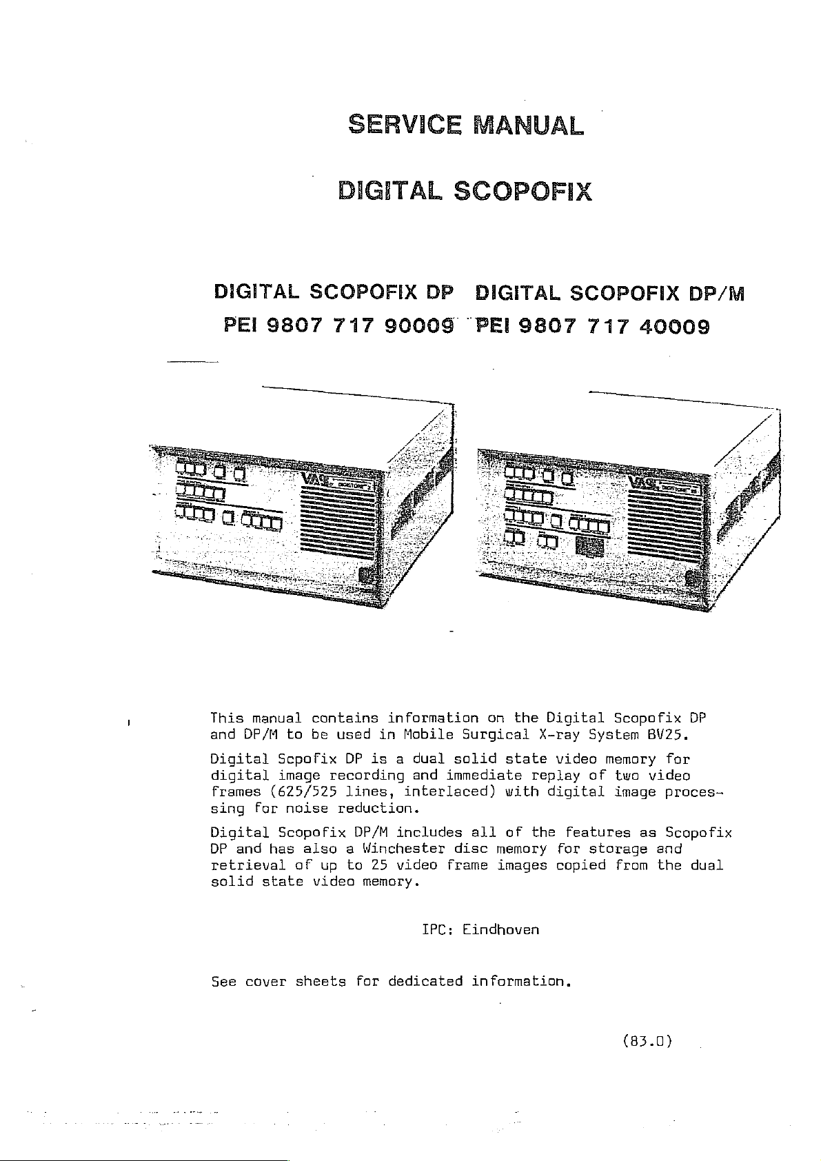
This
and
Digital
manual
DP/M
digital
frames
sing
Digital
DP
retrieval
solid
See
for
and
state
cover
contains
to
be
used
Scpofix
image
(625/525
noise
Scopofix
has
also a Winchester
af
sheets
DP
recording
lines,
reduction.
DP/M
up
to
video
for
information
in
Mobile
is a dual
and
interlaced)
includes
25
video
memory.
dedicated
solid
immediate
disc
frame
IPC:
on
the
Surgical
state
replay
with
all
of
the
memory
images
Eindhoven
information.
Digital
X-ray
video
digital
features
for
copied
Scopofix
System
memory
of
two
image
storage
from
(83.0)
BV25.
video
as
and
the
DP
for
proces-
Scopofix
dual
Page 4

Page 5
COVER
SHEET
DIGISTORE
1
This
document
requirements.
Additional
Digistore
lowing
1
sections
INTRODUCTION,
CONTROL
OPERATING
PARTS
AND
INSTRUCTIONS,
LIST
July,
is a general manual,
dedicated
is
not
Functional
CONNECTORS,
supplied
does
information
not
apply
specifications
Pin
Digistore
AND
DIAGRAMS,
System
1983
is
by
Philips;
to
callouts
block
not
being
presented
Philips
Digistore
1
diagram
all
units:
updated
on
this
Digistore
1
Digistore
ta
dedicated
cover
1
information
1
sheet.
Philips
in
fol-
Page 6

Page 7
COVER
SHEET * DIGISTORE
2
(Digital
Scopofix
DP)
This
requirements.
document
Additional
1.
The
following
INTRODUCTION,
INSTALLATION
OPERATING
2.
The
following
is a general
dedicated
INSTRUCTIONS,
If
installed
may
be
information
sections
FUNCTIONAL
+
EQUIPMENT
INSTRUCTIONS,
in
useful
specifications
in
July,
manual,
nat
is
of
manual
SPECIFICATIONS,
REQUIRED/NOT
RELAY
‚
POWER CABLE
MODES
BV25
understanding
OF
NOTE
system,
differ:
1983
being
presented
do
not
SUPPLIED
INTERFACE
OPERATION
however,
the
updated
on
this
apply
to
Power
2-ms
time
INSTALLATION
the
functions
to
dedicated
cover
Philips
up
diagnostics:
delay
mode
descriptions
of
the
sheet.
units:
for
Philips
unit.
Philips
default
is
units
-
Video
Video
Safety
Alignment
input
output
procedures
:
Video
will
:
Video
information
not
information
available
:
First units
Refer
:
Input
to
video
adjusted
be
clipped
if
applied
shipped
labeling.
calibration
for
1.1
up
aff
up
may not
Volt
to
1.1
to
1.1
ta
video input
of
Video
video
Volt
Volt
be
and
(video
will
UL/CSA
processor
0,3
only)
be
approved.
Volt
is
sync.
Page 8

Page 9
COVER
SHEET
DIGISTORE
25
(Digital
Scapofix
DP/M)
This
requirements.
Additianal
1.
document
The
following
INTRODUCTION,
INSTALLATION
OPERATING
If
may
.
The
following
is a general
dedicated
,
information
sections
FUNCTIONAL
EQUIPMENT
INSTRUCTIONS,
INSTRUCTIONS,
installed
be
useful
specifications
in
July,
manual,
of
manual
SPECIFICATIONS,
REQUIRED/NOT
RELAY
,
POWER
MODES
BV25
in
system,
understanding
not
is
presented
do
INTERFACE
CABLE
OF
OPERATION
NOTE
differ:
1983
being
not
SUPPLIED
however,
the
updated
on
this
apply
Power
Z-ms
to
up
time
Philips
INSTALLATION
the
mode
functions
to
dedicated
cover
diagnostics:
delay
of
sheet.
units:
for
descriptions
the
unit.
Philips
default
Philips
is
units
-
Video input
Video
Safety
Alignment
output
procedures
:
Video
will
:
Videa
available
:
First
Refer
:
Input
adjusted
information
not
be
clipped
information
if
units
to
video
shipped
labeling.
calibration
for
up
up
applied
1.1
Volt
to
1.1
off.
to
1,1
to
video input
may
not
of
video
Volt
Volt
be
UL/CSA
Video
and 0.3
(video
will
processor
be
approved.
Volt
only)
is
sync.
Page 10

Page 11
COVER
SHEET
This
requirements.
Additional
1.
document
The
DIGISTORE
is a general manual,
dedicated
following
"EQUIPMENT
"RELAY
“POWER
"MODE
DESCRIPTIONS”
information
sections
REQUIRED/NOT
INTERFACE
CABLE”
2
INSTALLATION/OPERATING
March
of
INSTALLATION"
is
Manual
SUPPLIED”
10,
not
presented
1983
do
being
not
INSTRUCTIONS
updated
on
this
apply
to
ta
dedicated
cover
Philips
Philips
sheet.
units:
The
If
installed
useful
following
Video
Video
in
understanding
specifications
input:
output:
UL/CSA:
in
Video
will
Video
available
First
to
BV
25,
not
labeling.
however,
the
functions
differ:
information
be
clipped
information
if
supplied
units
shipped
the
up
off.
of
up
to
may
mode
the
to
video
descriptions
unit.
1.1
to
1.1
not
be
volt
volt
input.
approved.
(video
will
may
be
only)
be
Refer
Page 12

Page 13
COVER
SHEET
This
requirements.
Additional
1.
document
The
DIGISTORE
is a general
dedicated
following
“EQUIPMENT
"RELAY
“POWER
“MODE
DESCRIPTIONS”
25
information
sections
REQUIRED/NOT
INTERFACE
CABLE"
INSTALLATION/OPERATING
March
manual,
of
INSTALLATION"
is
Manual
SUPPLIED"
10,
1983
not
presented
do
being
not
INSTRUCTIONS
updated
on
this
apply
to
to
dedicated
cover
Philips
Philips
sheet.
units:
The
If
installed
useful
following
Video
Video
in
understanding
specifications
input:
output:
UL/CSA:
in
BV
Video
will
Video
available
First
to
25,
the
differ:
information
not
information
units
labeling.
however,
functions
be
clipped
if
supplied
shipped
the
up
off.
of
up.
to
may
mode
the
to
descriptions
unit.
1.1
to
1.1
video
not
volt
input.
be
(video
volt
approved.
may
will
be
only)
be
Refer
Page 14

Page 15
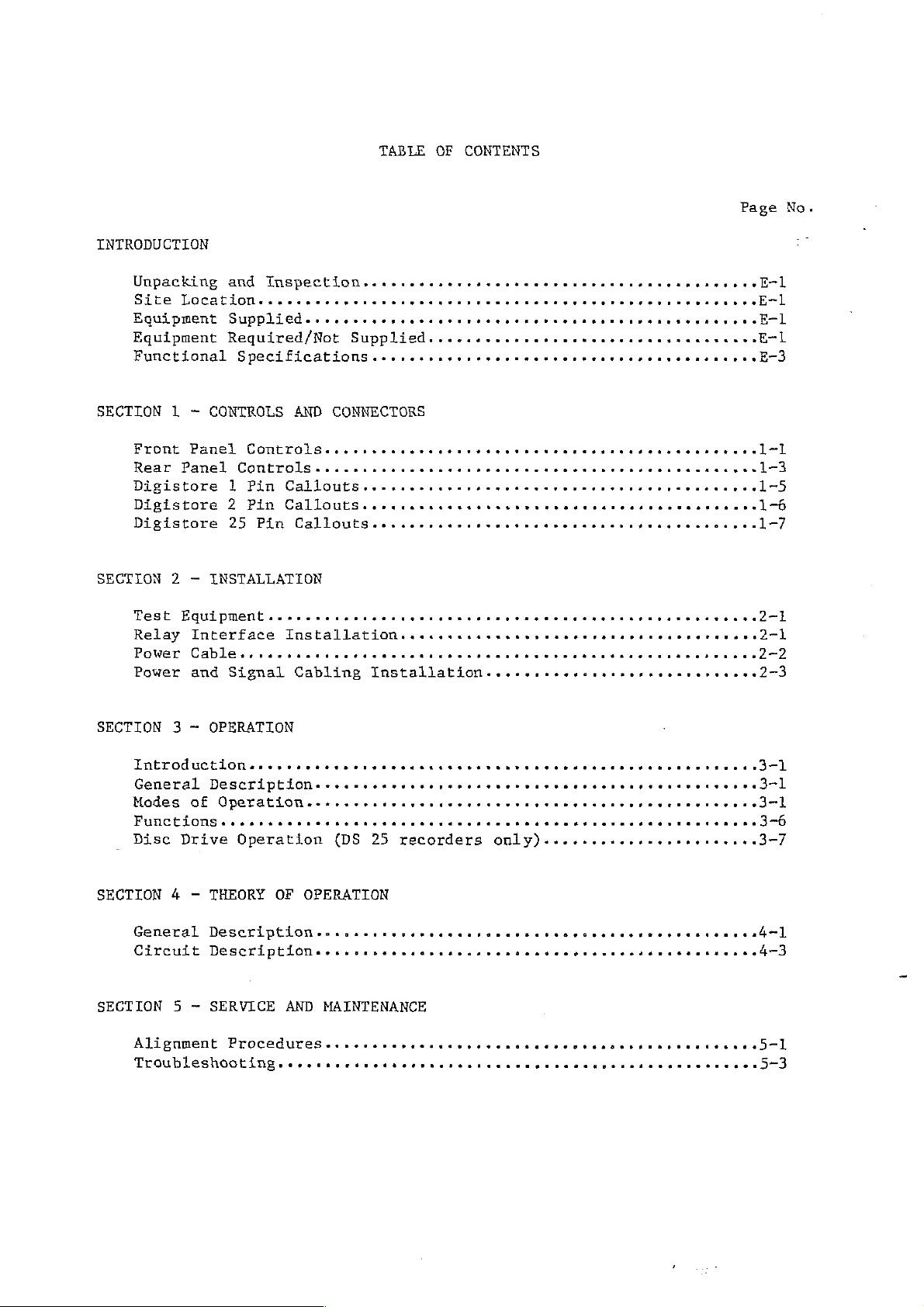
TABLE
OF
CONTENTS
INTRODUCTION
Unpacking
Site
qutpment
Equipment
Functional
SECTION
1 - CONTROLS
Front
Rear
DiSistore
Digistore
Digistore
SECTION
2 — INSTALLATION
Test
Relay
Power
Power
and
Inspection...
Locatione.csecnccerecer
Supp1ied
Reguired/Not
・・・
ο
Зирр11е4.
Specifications
AND
CONNECTORS
Panel
Panel
EQuipmenta.
Interface
and
Co
和
Controls....ccccoccrensro
1
Pin
Callouts
2
Pin
Callouts.
25
Pin
CalLouts
κ
ο
Signal
sec:
TnsEa11atgon
carice:riorio
ο
ο
Cabling
....sessssescseenssecssesenseesesessse
esc
ario
rs
ene
ο
ο
ети
renan
-1
.io
cio:
+ ュ < トニー
Installation...
cerco
cenci:
トー
トト トト
ο
ο
ο.
...,...4ssssserseessereue
トト
ο
rara
トッ て て
ドド と て と
ο.
rosceneranas
sero
000000000271
こく で >
ΟΙ“
or
eo
Page
συ
44]
ss
re
Er
1
.1-7
se
No.
El
一
3
1
1-3
-5
一
2)
2-2
273
SECTION 3 -
αν
Genera
Modes
Functions.
Disc
SECTION
GeneraL
Circuit
SECTION
Alignment
OPERATION
ο
ο
Κο
Descriptione
of
Qperationh
Drive
Operation
4 - THEORY
Description
БезсгЕреёЗоп
5 ~ SERVICE
Procedures..cccecerarcncorocenarceranocasr
ο
ο
ο
OF
OPERATION
AND
ο
«ο
ωοο ο ων
re
(DS
25
oo]
-
конь
MAINTENANCE
ев
Troubleshooting..cccrsecnenscernsercrcnanan
ο
κας
are
rase
recorders
она
изо
ο ο
ο
ric
ο
ο
ο
ο.
ни
aree
ово
sco
so re
racs
only).......s..esesssessuee3—7
оао
но
оу
ние
ο
ο...
ао
os
re
ri00vone
рева
sacos
нае + ДЗ
cosas
ο
3
00
一
37Ò
=]
İİ
Page 16
SECTION
7 ~ PARTS
LISTS
AND
TABLE
(continued)
DIAGRAMS
OF
CONTENTS
Page
No.
Replacement
System
System
System
Block
Block
Block
Block
Block
Block
Block
Wiring
Block
Block
Block
Diagram,
Diagram,
Diagram,
Diagram,
Diagram,
Diagram,
Diagram, Buffer
Diagram,
Parts
Diagrams-
Diagram,
Diagram,
Diagram,
Video
Video
System
Arithmetic
Phase
Memory.s.ss::
System
oo
Digistore
Digistore
Digistore
1....,.....s.sssessesseusssmusire
2...
25...,.....4...sesessssmseuesetse
INpUt..eooooomooncrarcanancaconasanacao
OutpUt.cnnonroorocaracococananacnorascanacao
Controller.........,.,....s.sessssesssessse.6
Logic
Lock
Loop・・・・・・・・・
Memory.(DS
POWEr....sesrerioreciceraseresioreris
Uniť....+....+.....+«4<.<s+++144++Ď
cio
ce
cer
sce
25
recorders
00000
acero
only)+..+.o.......
0erenene
roca
00000
ese
o
«6-11
re0
6
6
6
и
О
Ó
«0-9
06710
6712
Nr
Bo
OÚ
oN
Page 17
INTRODUCTION
UNPACKING
Carefully
carton
surfaces,
immediately
SITE
Install
The
surface,
firm
EQUIPMENT
The
LOCATION
Digistore
contact
following
One
One
One
AND
open
and
inspect
broken
notify
the
Digistore
such
SUPPLIED
Digistore
Power
Technical
INSPECTION
the
knobs, dented
the
Recorder
as
a
with
the
equipment
Recorder
Cord
Manual
instrument
for
evidence
shipping
Recorder
must
table,
floor.
is
(if
on
shipping
of
physical
case,
agent
in a well-ventilated
be
shelf,
and VAS
installed
or
supplied:
purchase
order)
carton, remove
damage
etc.
instrument
If
there
Corporation.
on
a
the
such
are
area.
solid-based,
cart
with
instrument
as
any
signs
horizontal,
all
scratched
of
four
from
damage,
wheels
the
panel
level
in
One
The
ordered.
EQUIPMENT
To
furnished
short
seconds
should
the
than
bill
provide
Recorder
specified
User's
REQUIRED
period
on
be
of
for
by
60
set
Guide
materials
/NOT
use
the
X-ray
of
time
Hz
units)
to
record
as
short
above.
The
such
cause
of
(minimum
method
that
X-ray
packed
SUPPLIED
the
Last
manufacturer
after
the
as
possible
used
a
actuation.
with
Image
of
80
the
last
component
image
to
WARNING
to
the
Hold
milliseconds
footswitch
provide
to
avoid
failure
feature,
delay
after
Recorder
termination
on
is
released.
footswitch
unnecessary
delay
must
will
identifies
a
time
50 Hz
be
not
delay
of
units
This
release.
radiation,
the
circuit
the
and
equipment
must
X-ray
68
delay
The
but not
for
milli-
allows
delay
less
be
a
Page 18

Page 19
FUNCTIONAL
SPECIFICATIONS
Video
Analog
Number
to
of
input
digital
Images
Image
Memory
requirements:
Sampling
Video
stored:
format:
converter:
output:
depth:
rate:
DS
1:
One
memory.
DS
2:
Two
frames
DS
25:
Two
frames
on
disc.
640 x 512 x 8
Frame
Winchester
1.0
posite
or
specified
8
NTSC:
CCIR:
Number
each
fied)
volt
CCIR
bit.
store:
peak-to-peak
video
compatible.
input,
12.096
12.000
of
independent
with
1
composite
Disc
frame
frames
bit.
10
signal,
MHz.
MHz.
volt
or
two
in
solid
in
bit.
Drive:
peak
8
(or
75-ohm
whites
video
peak-to-peak
video
signal,
state
solid
bit.
other
If
fields
memory
termination;
video
will
outputs‘:
(or
75-ohm
in
state
as
specified)
input
be
other
solid
memory;
state
com-
RS-170
exceeds
clipped
one
as
off.
or
speci-
two,
termination.
25
Signal~to-noise
Digital-to-analog
Arithmetic
Video
Record
Storage
Control
bandwidth:
ratio:
converter:
format:
processing:
media:
Electrical:
logic:
Controls:
—3
dB
point
Better
8
bit.
DS
nically
DS
memory.
Available
64K
90-132
User
Microporcessor
Most
MODE
NOISE
MONITOR
SEQ
MONITOR
than
1:
One
in
2
&
25:
dynamic
or
selectable
functions
Switches:
REDUCTION
L:
(DS 2 and
2:
at
4.2
54
dB.
frame
solid
One
for
all
access
180-250
controlled,
have
ON,
25
ON,
FRM,
MHz.
or
two
state
video
frames
memory.
volts
on
back
remote
ER,
LIH,
Switches:
FRM,
FLD
only))
FLD
fields
memory.
frame
during
AC,
panel.
TIL
capability.
FL,
ON/OFF,
1,
1,
FLD 2 (DS
are
in
record.
47-63
compatible.
REC/BSY
FLD
2
stored
each
Hz.
(os o à
solid
2 &
electro-
state
3)
25
only)
E-3
Page 20

Disc
Drive
(Digistore
Specifications
25
only)
FUNCTIONAL
SPECIFICATIONS
(Continued
)
Transfer
Access
from
Disc
time
Data
frame
Frame
transfer
Drive
Controls:
Disc
Disc
to
disc
to
disc
Store
to
Reliability:
Speed:
Motor:
image:
time
image
Disc:
of
TRANSFER:
DISC:
TRACK
Approximately
DC
Approximately
Approximately
Manual
Better
REV,
Indicator
brushless.
or
than
AUTO,
Automatic.
MAN
FWD
3600
2
2
10,000
secands.
seconds.
RPM.
power-on
hours.
E-4
Page 21
FUNCTIONAL
SPECIFICATIONS
(Continued)
Power
Safety:
Environmental:
Mounting:
Up
Diagnostics:
Unit
safety
Operating
Relative
Size:
will
standards.
Temperature:
Humidity:
Width
meet
Depth
Height
Rack
always
of
battery voltage
volts,
or
Battery
2.3
low,
indicating
“battery
comparator
troller,
all the
puts
panel.
all
on
Noise
(third
lamp
failure.
Operation
tion
will
unit
is
a
a
the
and
Reduction
will
ON/OFF
assume
was
operational
default
table.
Check:
compared
volts.
the
output
marginal".
is
and
normal
pattern
The
user
lights
then
highest)
be
The
by
turned
setup.
UL,
CSA,
80%
non-condensing.
-
17"
-
23"
—
9.1"
The
battery voltage
with
a
On
power
has
of
“battery
fallen
a
This
monitored
instead
initializations,
of
lights
will
on
the
off,
user
pressing
lamp
noise:
lit,
and
indicating
can
Switch.
the
setup
off,
(remember
IEC,
O°C
Eo
maximum,
(431.8
(584.2
(222.25
threshold
up,
comparator
failure”
output
by
of
going
on
first
front
then
and
the
reduction
continue
the
Noise
The
front
selected
providing
variables),
and
407C.
um)
mm)
mm)
below
the
the
notice
panel
that
number
VDE
value
if
the
2.3
goes
of
the
con-
through
it
out-
front
that
turn
value
battery
normal
Reduc-
panel
before
the
is
or
the
8
RAM
or
Fifty/Sixty
video
rear
initializations
The
then
ON/OFF
Noise
warning
The
video
and
the
E-5
is
50
panel
user will
turn
off,
lamp
Reduction
the
user
resume
Noise
or
can
the
Reduction
Check
Hz
is
notice
and
user
switch
normal
and the
set
will
then
number
value
of
then
operation
ON/OFF
If
the
switch
for
60
Hz,
not
all
the
lamps
Noise
be
Reduction
16
lamp
either change
on
the
wrong
the
switch.
will
rear
by
incoming
on
the
normal
started.
turn
on,
(highest)
be
lit,
setup.
the
panel
pressing
Page 22
x
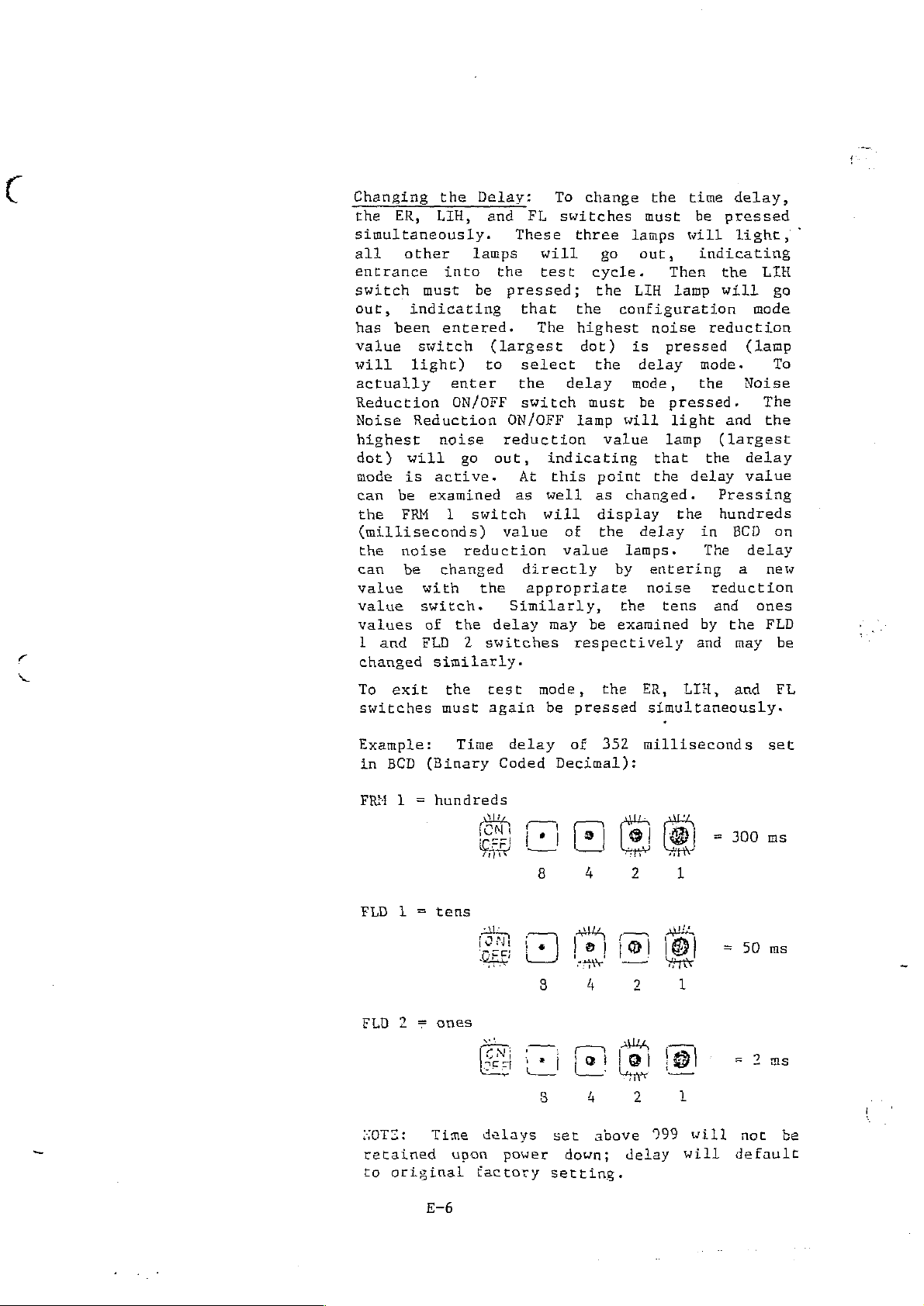
Changing
the
ER,
the
LIH,
simultaneously.
all
entrance
switch
out,
has
value
will
actually
Reduction
Noise
highest
dot)
mode
can
can
value
value
other
must
indicating
been
switch
light)
Reduction
noise
will
is
active.
be
examined
the
FRM
(milliseconds)
the
noise
be
with
switch.
values
1
changed
and
of
FLD
similarly.
into
entered.
enter
ON/OFF
go
1
reduction
changed
the
2
Delay:
and
lamps
the
be
pressed;
(largest
to
ON/OFF
reduction
out,
switch
value
the
delay
switches
To
FL
switches
These
will
test
that
The
select
the
delay
switch
indicating
At
this
as
well
will
of
value
directly
appropriate
Similarly,
may
respectively
change
the
must
three lamps
go
out,
cycle.
the
LIH
the
configuration
highest
dot)
the
must
lamp
value
point
as
display
the
be
noise
is
delay
mode,
be
will
that
the
changed.
delay
lamps.
by
entering
noise
the
tens
examined
time
be
will
indicating
Then
lamp
reduction
pressed
mode.
the
pressed.
light
lamp
delay
the
in
by
and
(largest
the
Pressing
hundreds
The
reduction
and
delay,
pressed
light,
the
LÍH
will
go
mode
(lamp
To
Noise
The
and the
delay
value
BCD
delay
a
new
ones
the
FLD
may
on
be
To
exit
switches
Example:
in
BCD
FRM 1 =
FLD
1
FLD 2 =
SOTE:
retained
to
original
the
must
(Binary
hundreds
=
ones
Time
Time
Gee)
ολα
delays
upon
factory
test
again
delay
Coded
END
power
mode,
be
pressed
of
Decimal):
(+1
8
기니
lo]
[ο]
Ti
Fa)
Κο
8
ser
down; delay
setting.
the
352
(e)
lo]
4
>
ja)
[8]
4
È
4
above
ER,
LIH,
simultaneously.
milliseconds
(8)
2
1
Bİ
2
1
|
2
1
999
will
will
and FL
300
-
=
50
=
not
default
set
no
ms
2
be
E-6
Page 23

Page 24

Page 25

CONTROLS
AND
CONNECTORS
MODE
SELECTIONS
ER
LIH
FL
NAME
Places
of
mizing
Stepping
ates
automatically
depressed.
memory
Places
operation.
fluoroscopic
recording
recorded
l
or
Places
tion.
while
Images
switch
the
operation.
the
a
recording.
(Monitor
the
2).
the
Fluoro
pressing
can
is
recorder
X-ray
on
the
terminated
The
recorder
Last
image
an
image
image
recorder
is a means
be
recorded
depressed.
in
Electronic
exposure
footswitch
Upon
recorded
1
or
2).
Image
when
is
displayed
in
the
footswitch,
FRONT
DESCRIPTION
the
completion
although
image
in
the
Hold
while
the
the
of
by
pressing
PANEL
ER
(Electronic
Radiography
required
energizes
is
displayed
LIH
(Last
is
a
pressing
footswitch
from
FL
viewing
the
(Fluoroscopic)
without recording
is
to
the
of
the
the
means
the
selected
a
live
"REC/BSY"
Radiography)
a
means
record
X~ray
recording,
footswitch
from
Image
of
viewing
footswitch,
is
memory
fluoroscopic
while
of
an
and
the
Hold)
released.
mode
of
an
the
mode
mini-
image.
initi-
X-ray
remains
selected
mode
a
live
(Monitor
opera~
image
image.
foot-
is
of
and
The
REC/BSY
NOISE
ON/OFF
SUB
REDUCTION
Places
tion.
the
Subtract
"difference"
causes
which
REC/BSY
tional
steady
Turns
available
Pressing
tion,
exposure
the
the
(Record/Busy)
in
during
on
smoothing
recorder
is
between
automatic selection
first
any
or
in
Noise
time
image
of
recording
off
all
modes
Reduction
will
a
the
Noise
the
increase
in
means
two
or
is
recorded
the
of
selected
“mask”
a
manual
above
process
Reduction
to
reduce
value
with
1-1
SUB
visualizing
of
is
modes.
and
feature.
random
switches
image.
increased
(Subtract)
images.
Monitor
to
be
recorded.
recording
The
while
noise.
increases
In
mode
and
recording
Pressing
2,
the
command, opera-
REC/BSY
X~ray
Noise
the
noise
lamp
is
Reduction
noise
ER
mode,
reduction.
of
opera“
SUB
monitor
lights
actuated.
reduc-
the
also
on
is
X-ray
Page 26

CONTROLS
AND
CONNECTORS
MONITOR
FLD
DISC
NAME
(MEMORY)
ON
FRM
1/FLD
SEQ
TRANSFER
AUTO
2
SELECTIONS
Determines
monitor
Selects
Selects
mode
which
Places
recorded
Monitor
CONTROLS
Activates
Transfer
into
stored
into
will
Frame
Field
reduces
field
the
and
2.
(Digistore
or
is
the
selected
on
the
which memory
display
Mode
Mode
blurring
will
be
recorder
displayed
25
deactivates
activated
disc.
FRONT
DESCRIPTION
recorded
of
image
of
image
due
displayed
in
alternately
only)
(AUTO
memory
PANEL
the
image.
display
display
to
on
the
Automatic
lamp
(Monitor
image
(one
image
Sequential
motion.)
selected
lit),
L
is
recorded
frame = two
(Viewing
monitor.
Mode.
between
Transfer.
each
or
Monitor
in
and
determines
Images
Monitor
When
image
2)
and
fields)
the
1
stored
is
which
field
are
and
Auto
also
MAN
REV
FWD
TRACK
Manual
(MAN
(Monitor
NOTE:
lamp
The
exclusive.
either
only
mode.
Reverse
counter
pressed.
the
(Monitor
Forward
counter
pressed.
the
(Monitor
Indicates
track
(Monitor
the
to
designated
designated
number
Transfer.
lit),
1
or
Automatic
Pressing
Automatic
transfer
stepping.
at
approximately
Upon
1
or
stepping.
at
approximately
Upon
1
or
count
1
or
an
Monitor
images,
release
track
Monitor
release
track
Monitor
of
of
Monitor
When
image
2) to
and
“AUTO"
or
Manual
Pressing
of
is
2).
Pressing
of
is
2).
images
image
2)
Manual
is
transfereed
disc
Manual
alternately
mode.
not
to
this
two per
the
transferred
this
two
per
the
transferred
transferred
transferred
from
the
Transfer
by
pressing
Transfer
activate
switch
second
switch,
switch
second
switch,
disc.
from
places
The
the
decrements
while
the
to
the
increments
while
the
to
the
to
to
mode
modes
is
selected
this
are
activated
switch.
recorder
MAN
switch
Manual
the
the
switch
image stored
selected
the
the
switch
image
selected memory
the
selected
stored
disc
memory
mutually
into
is
used
Transfer
track
memory
track
and/or
memory
is
on
is
on
1-2
Page 27

CONTROLS
AND
CONNECTORS
VIDEO
VIDEO
DESCRIPTION
SIGNAL
EXT.
SIGNAL
(1 & 2)
50/60
REMOTE
CONTROL
INPUT
SYNC.
OUTPUT
HZ
The
input
to
this
signal
specified.
User
tinuous
playback
an
The
nected
The
video
60
The
terminal.
optional feature.
external
output
position
frequency
Hz.
optional
video
terminal.
level
video
video
to
these
should
sync
video
of
remote
REAR
syne
is
terminls.
PANEL
FUNCTION
signal
The
be
looped
may
be
signals
this
of
the
to
impedance
1.1
In
signal
required.
switch
recorder
control
the
volt
situations
is
back
to
the
determines
is
recorder
is
peak-to-peak
not
to
the
monitors
is to
connected
is
75
ohms
possible,
input
whether
be 50
connected
and
where
are
to
the
or
con-
video,
com
the
Hz
this
as
or
or
MAINS
INTERFACE
115V/220V
POWERINPUT
Fl & 了
2
The
electrical
interface
The
position
voltage
The
mains input
terminal. Verify
set
to
Two
fuses
AC
line.
of
the
Replace
relays
of
the
correct
are
connections
are
connected
this
recorder
power
that
input
provided
only
switch
is
cable
the
voltage
to
when
for
the
to
determines
to
be
115
is
voltage
position.
protect
necessary.
X-ray
this
connected
or
select
both
terminal.
220V。
sides
generator
whether
to
switch
of
the
this
is
the
1-3
Page 28

Page 29

DIGISTORE
1
PIN
CALLOUTS
Pin
No.
L
2
3
&
5
6
7
8
9
10
11
12
13
14
15
16
17
18
19
Funetion
Cable
Gnd
ER
LIH
FLUORO
RECORD
Not
available
NOISE
Weight
Weight
Weight
Weight
Frame
Field
Field
DS
Busy
Not
available
Not
available*
Not
used
Shield
REDUCTION
#2
#4
#8
#16
1
2
Indicator
REMOTE
CONNECTOR
Pin
.
No.
20
21
22
23
24
25
26
27
28
29
30
31
32
33
34
35
36
37
Funetion
+SV*
Not
available
Not
available
Not
available
Not
available
Not
available
Not
available
Not
available
Not
available
Not
available
Not
available
Not
available
Not
available
Not
available
Gnd
Not
used
Noise
Not
used
Reduction
Indicator**
*1
AMP Max.
**Open
Pin
NOTES:
1.
24V
2.
Not
3.
Unused
Collector
No.
1
2
3
4
5
6
7
8
9
10
11
12
13
AC/DC
polarity
inputs
Outputs
Function
Cable
Not
Not
Not
Not
Not
Not
Shield
available
available
available
available
available
available
Start)
Start!
Terminate?
Terminate?
Not
used
50/60
Max.
Hz
sensitive
shall
INTERFACE
Lo = 60
not
be
Hz
terminated.
CONNECTOR
Fin
No.
14
15
16
17
18
19
20
21
22
23
24
25
Function
Not
used
Not
used
Not
used
Not
used
Not
used
Not
used
Not
available
Not
available
Bypass
Not
used
Not
used
Gnd
1-5
Page 30

DIGISTORE
2
PIN
CALLOUTS
Pin
No.
ER
mW
alamı
wo
10
11
12
13
14
15
16
17
18
19
Function
Cable
Gnd
ER
LI
FLUORO
RECORD
OPTION
NOISE
Weight
Weight
Weight
Weight
Monitor
Frame,
Field
DS
Busy
Not
available
Sequence
Not
used
Shield
REDUCTION
#2
#4
#8
#16
1
Select
Monitor
1,
Monitor
Indicator
Indicator*
REMOTE
1
1
CONNECTOR
Pin
No.
20
21
22
23
24
25
26
27
28
29
30
31
32
33
34
35
36
37
Function
+5VA
Field
SEOUENCE
Monitor
Frame,
Field
Field
Not
available
Not
available
Not
available
Not
available
Not
available
Not
available
Not
available
Gnd
Not
available
Noise
Not
used
2,
Monitor
2
Select
Monitor
1,
Monitor
2,
Monitor
Reduction
L
2
2
2
Indicator**
Y
#1
AMP
**Open
Pin
NOTES:
1.
24V
ュ
Not
3.
Unused
Max.
Collector
No.
Cable
ru
La
E
La
0
Y
CO
10
mr
ro
=
το
r
ts
AC/DC
polarity
Not
Not
inputs
Outputs
Function
Shield
available
Not
available
Not
available
Not
available
available
Not
available
Start!
Start!
Terminate?
Terminate”
Not
used
50/60
Max.
ilz
sensitive
shall
INTERFACE
[о = 60
not
be
CONNECTOR
НЕ
cerninaced.
Pin
No.
14
15
16
17
18
19
20
21
22
23
24
25
Function
Not
used
Not
used
Not
used
Not
used
Not
used
Not
used
Not
available
Not
available
Bypass
Not
used
Mot
used
Gud
1-6
Page 31

DIGISTORE
25
PIN
CALLOUTS
Fin
No.
1
2
3
4
5
6
7
8
9
10
11
12
13
14
15
16
17
18
19
Function
Cable
Shield
Gnd
ER
LIH
FLUORO
RECORD
OPTION
NOISE
REDUCTION
Weight
Weight
Weight
Weight
Monitor
Frame,
Field
DS
Busy
Auto
Sequence
Not
Transfer
used
REMOTE
CONNECTOR
JI
Pin
#2 28
#4
#8
#16
1
Select
Monitor
1,
Monitor
Indicator
Indicator**
1
1
Indicator
No.
20
VAŠ
22
23
24
25
26
27
29
30
31
32
33
34
35
36
37
Function
+5VA
Field
SEQUENCE
Monitor
Frame,
Field
Field
Auto
Transfer
Manual
Reverse
Forward
Count
Count
Counter
Gnd
Track
Noise
Not
used
2,
Monitor
2
Select
Monitor
1,
Monitor
2,
Monitor
Transfer
Step
Step
Up
Down
Reset
Limit
Reduction
1
2
MN
Indicator**
Kl
AMP
Max.
**Open
Pin
Collector
No.
RE
LO
S
ain
won
10
11
12
13
*I£ a special
See
Special
Outputs
Function
Cable
Not
available
available
Not
Not
available
Not
available
Not
available
Not
available
Start}
Start!
Terminate?
Terminate?
Not
used
50/60
customer
Interface
Shield
Hz Lo
interface
Callouts,
INTERFACE
=
60
Hz
is
Connector
CONNECTOR*
J2
required,
J-2A
Pin
No.
14
15
16
17
18
19
20
21
22
23
24
25
this
for
connector
external
Function
Not
used
Not
used
Not
used
used
Not
Not
used
Not
used
Not
available
Not
available
Bypass
Not
used
Not
used
Gnd
may
be
connections.
internal.
NOTES:
1.
24V
2.
Not
3.
Unused
AC/DC
polarity
inputs
Max.
sensitive
shall
not
be
terminated.
1-7
Page 32

Page 33

Page 34

Page 35

INSTALLATION
INSTRUCTIONS
TEST
equipment.
RELAY
One
EQUIPMENT
Installation
INTERFACE
end
connector.
cable.
follows:
A.
Standard
X-ray
stand
Digistore
1.
2.
of
the
The
To
install
Standard
Custom
generators
an
Disconnect
Connect
interface
of
the
INSTALLATION
35-foot
relay
Interface:
Interface
extra
Recorder
Digistore
Relay
circuit
the
Relay
Interface:
with
load
through
footswitch
the
as
follows:
X-ray
Interface
Refer
Refer
24V
of
Recorder
Interface
board
to
to
dc
power
100
mA,
the
Relay
from
K-ray
equipment
requires
cable
is
attached
circuit
paragraph
paragrpah
available,
can
Interface
generator.
and
is
B.
be
no
special
fitted
at
the
board
A.
assembly,
and
connected
circuit
footswitch
tools
with
other
which
directly
board.
to
a
multi-pin
end
proceed
can
the
or
of
to
test
the
as
with-
the
relay
3.
TERMINAL
TB25,
FOOTSWITCII
TERMINATE
Connect
rear
LABELED
-V
+START
-START
TB26
+V
the
of
the
25-pin
recorder.
24V
dc
power
Red
wire
Black
At
of
wire
generator
disconnected
Footswitch
24V
dc
power
Green
cable
and
plug
2-1
CONNECT
supply
VAS
of
in
leads,
supply
white
to
TO
negative
Interface
VAS
Interface
where
original
step L above.
positive
wires
the
of
INTERFACE
Cable.
Cable.
VAS
(-).
footswitch
(+)
Interface
connector
Cable.
at
was
the
Page 36

B.
Custom
Interface:
When
Custom
Interface
Wiring
and
The
from
1.
2.
24V
X-ray
Custom
115V
Disconnect
Connect
follows:
de
is
(Electronic
is
housed
connections
equipment
Interface
ac.
footswitch
X-ray
TERMINAL
115V
This
applied
power
FOOTSWITCH
not
equipment
LABELED
AC
to
the
available
Radiography)
in a metal
between
are
accomplished
contains
from
IN
must
be
X-ray
to
Interface
case.
the
relay
a
X-ray
and
footswitch
Hot
NOTE
present
generator.
Footswitch
operate
circuit
at
power
generator.
side
whenever
the
interface
is
board
terminals
supply
to
the
CONNECT
of
115V
(Disconnected
required.
and
on
and
operates
relay
TO
ac
source.
power
circuits,
the
the
metal
interface
is
in
The
Custom
footswitch
case.
directly
step
1).
the
as
POWER
The
which,
ment.
pin-
3.
Connect
rear
CABLE
Digistore
when
The
X-RAY
(2
the
of
the
Recarder
connected
offset
The
power
or
a
hazard
tor, the
ON
terminals)
25-pin
recorder.
is
to
pin
on
and
will
patient,
cable
equipped
an
appropriate
the
ground
and
Terminals
disconnected
plug
power
to
with
cable
WARNING
connections
exist
for
other
persons
the
a
power
three-prong
must
the
equipment
where
INTERFACE
three~conductor
outlet,
in
in
footswitch
step
grounds
plug
be
correct,
the
room.
opera-
was
l.
connector
power
is
the
the
at
the
cable
instru-
ground
Page 37

POWER
AND
SIGNAL
CABLING
INSTALLATION
The
correct
connecting
75-ohm
time
tion
line.
input
monitor
nation
and
end,
For
to a line
position
If
the
back
of
the
to
of
the
monitor
the
recorder
recorder
termination
impedance
as
the
end-of-line
cables
video
the
not
example,
loopthru
switch
rather
recorder
the
video
75-ohm
output.
output
position;
SPECIAL
routing
line
termination
at
coming
connection,
must
than
is
video
system
termination
position.
If
to
switch
termination.
and
is
extremely
must
an
intermediate
when
from
be
set
the
75-ohm
later
monitor,
without
it
is
only
must
the
video
NOTE
termination
be
terminated
must
connecting
in
be
the
the
the
position.
disconnected
for
the
switch
The
same
desired
one
monitor,
be
placed
recorder
of
important.
at
the
point
the
back
monitor
high
proper
disc
must
is
to
in
the
video
only
destina-
of
recorder
of a video
termi-
impedance
from
operation
recorder,
be
returned
true
of
connect
the
monitor
the
will
serve
Any
one
the
the
the
the
high
Power
Connect
and
1.
2.
3.
power
Connect
and
Connect
Connect
signal
and
to
terminal.
signal
recorder
power
monitor
video
connectors
cables
power
source
INPUT
signal
are
as
cable
outlet.
to
source
located
follows:
recorder
(camera)
to
at
recorder
VIDEO
OUTPUT
the
three-prong
OUT
terminal(s).
recorder
to
recorder
rear
panel.
receptacle,
VIDEO
IN
2-3
Page 38

Page 39

Page 40

Page 41

3.
OPERATING
INSTRUCTIONS
1.0
INTRODUCTION
Operation
random
Actuation
cause
data
and
and
liar
GENERAL
The
which
he
trator,
images
MODES
sequence
damage
not
followed
full
with
DESCRIPTION
Digistore
for
Digistore
including
for
OF
of
the
of
the
to
recorded
by
use
of
the
instructions
1
record
1
subsequent
OPERATION
Digistore
as
may
controls
the
as
the
the
Video
and
Recorder
mobile
DIGISTORE
be
required
equipment;
desired
operator.
equipment
Recorder
playback
"O.R."
replay,
1
1
is
in
any
if
To
capabilities,
presented
is a solid
of
is
designed
units,
study,
VIDEO
straightforward
however,
still
RECORDER
by
the
sequence
the
basic
obtain
in
picture
for
and
operator.
recorded
maximum
this
to
detailed
or
combination
procedures
the
manual.
state
video
operation
record
and
may
be
performed
thereof
data
performance,
operator
recording/playback
sequences
analysis.
are
images.
with
can
not
should
any
of
will
be
erased
understood
reliability,
be
system
X-ray
still
in
not
or
fami-
gene-
video
a
The
Digistore
Image
Select,
operation.
During
with
The
Fluoroscopy
cause
A.
Hold,
NOISE
record
the
Electronic
Electronic
is
single
duces
fluoroscopy
then
remains
quality
patient.
1
and
and
contrast
Power
Up,
REDUCTION
modes,
(FL)
exiting
short-exposure
video
a
new
automatically
depressed.
recordings
has
three
Fluoroscopy.
control
the
Digistore
off,
Electronic
are
mutually
of
the
Radiography
Radiography,
still
single-image
exposure
modes
(optional)
FRAME
Radiography
exclusive
other.
(ER)
which
Fluoroscopy
picture.
recording.
to
continue
terminates
Exposure
with
minimum
of
operation,
In
addition,
1
will
selected.
can
with
Each
the
time
possible
Noise
have been
assume
(ER),
and
merely
be
used
simultaneous
actuation
The
only
exposure
until
is
Electronic
Reduction,
added
the
ER
Last
entering
with
of
VAS
Interface
the
even
adjusted
X-ray
Radiography,
for
mode
Image
any
recording
the
image
though
to
exposure
Frame/Field
enhancement
of
operation,
Hold
X-ray
(LIH),
one
generator,
footswitch
circuit
is
the
footswitch
obtain
time
Last
mode
of
will
a
pro-
allows
recorded,
optimum
to
of
and
new
the
Page 42

The
Last
tion.
the
recorder
closure
noise
averaging
switch,
in
the
To
record
follows:
1.
Select
2.
Select
desired
3.
Select
Image
Without
and
will
reduction,
process
the
averaging
selected
and
the
Noise
weighting
FRAME
Recordings
FIELD
playback
Selection
display
Hold
noise
into
memory.
display
LIH
mode;
images,
of
recording
reduction,
the
bypass
store
depression
per
or
of
each
the
the
of
images
Mode
Reduction
value.
FIELD
can
be
however,
"FLD"
field
next
of
selected
the
(Press
mode
made
select
will
mode
last
in
if
NOTE
for
1
(%
the
"LIH").
(Press
Frame
operate
depression
for
frame
footswitch
weighting.
sequence
the
Last
desired
“FRM”
in
either
optimum
mode
or
"FLD
frame)
with
of
the
duration
after
footswitch
Upon
of
images
Image
(Press
or
the
resolution
(Press
2"
allows
separately.
or
without
the
footswitch
will
release
Hold
“ON/OFF").
"FLD").
FRAME
"FRM").
of
cause
will
mode,
or
of
for
noise
the
footswitch
release.
a
continuous
of
the
be
maintained
proceed
will
reduc-
put
With
foot-:
as
Select
4.
5.
Fluoroscopy
Recordings
memory,
another
To
record
1.
Select
2.
Select
weighting
Select
NOTE:
(Pre
Press
image.
terminates
footswitch
Release
X-ray.
selected monitor.
Repeat
but
mode
in
made
will
of
the
the
Fluoroscopy
Noise
Step 4 as
in
the
not
operation,
Fluoroscopy
Reduction
value.
FRAME
For
Fluoroscopy
or
FIELD
optimum
to
of
necessary
Fluoroscopy
appear
such
mode
mode.
resolution
turn
the
The
on
mode,
if
on
footswitch
last
to
(bypass)
the
monitor
as
ER.
proceed
(Press
desired
of
X-ray
image
record
as
"FL")
(Press
playback
and
completes
recorded
and
mode will
until
follows:
“ON/OFF).
images,
display
recording
display
recorder
will
desired
be
select
live
recorded
fluoroscopic
sequence
remain
is
Select
on
images.
into
switched
desired
Frame
and
the
the
to
Mode
Page 43

4.0
To
fluoroscopy
to
in
will
recorded
footswitch
FUNCTIONS
A.
Noise
make
record
memory
continue
Reduction
a
recording,
will
the
until
image
terminates
be
desired
replaced
to
be
will
(ON/OFF)
press
displayed
image
by
displayed
not
be
X-ray.
footswitch.
on
the
into
memory.
a
newly
as
long
displayed
The
selected
The
recorded
as
the
on
the
X-ray
monitor.
recorded
image.
footswitch
monitor.
will
turn
Press
image
Live
is
Release
on
and
“REC/BSY”
will
pressed;
remain
fluoroscopy
of
live
the
the
This
vated
be
the
noise
In
In
The
value
footswitch
Frame
Either
images.
Recording
memory
however,
mode.
Displaying
motion.
Contrast
function
following
assumed.
same
reduction
ER
mode,
LIH
relative
/Field
value
the
mode,
selected.
release.
Select
the
FRAME
in
which
for
images
Enhancement
is
power
Once
will
until
weighting
each
value
the
can
optimum
available
up,
a
value
return
a
incoming
assigned
The
result
(FRM/FLD)
or
FIELD
Field
be
displayed
resolution,
in
(optional)
of
new
represents
mode
Mode
the
the
upon
FIELD
in
the
ER and
minimum
weighting
re-entering
value
video frame
to
each
of
the
can
allows
separately
is
selected.
the
frame
last
be
for
images
Mode
LIH
weighting
is
selected
the
number
is
averaged
is
average
selected
storage
by
should
reduces
modes.
of 2 will
and a mode
same
of
frames
with
determined
remains
for
of
pressing
be
recorded
image
When
mode
record
two
FLD
flicker
first
automatically
is
and
requesting
integrated.
a
stored
by
the
in
memory
or
display
field
1
in
acti-
exited,
frame.
weighting
images
or
FLD
the
Frame
caused
upon
of
in
2;
by
The
Contrast
gray
viewing
to
increase
of
specific
Enhancement
contrast
areas.
control
of
recorded
changes
images
the
weighting
providing
of
for
the
more
shades
detailed
of
Page 44

Page 45

OPERATING
INSTRUCTIONS
1.0
2.0
3.0
INTRODUCTION
Operation
random
Actuation
cause
data
and
and
liar
GENERAL
The
for
The
rator,
images
MODES
sequence
damage
not
followed
full
with
DESCRIPTION
Digistore
storage
Digistore
including
for
OF
of
the
of
the
to
recorded
by
use
of
the
instructions
2
and
2
subsequent
OPERATION
Digistore
as
may
controls
the
as
the
operator.
the
Video
display
Recorder
mobile
DIGISTORE
be
required
in
equipment;
desired
equipment
Recorder
of
is
“O.R.”
replay,
2
VIDEO
2
is
straightforward
any
if
To
capabilities,
presented
is a solid
still
picture
designed
units,
study,
by
the
sequence
however,
the
basic
obtain
in
and
RECORDER
operator.
or
recorded
maximum
this
state
video
for
operation
to
record
detailed
and
combination
procedures
performance,
the
operator
manual.
recording/
images.
sequences
analysis.
may
data
with
be
can
are
performed
thereof
be
not
reliability,
should
playback
any
of
will
erased
understood
be
X-ray
still
in
not
fami-
system
gene-
video
a
or
The
Digistore
Image
Reduction,
have
During
with
The
Fluoroscopy
entering
Ae
Hold,
been
SEQUENCE
record
Electronic
Electronic
is
single
duces
Fluoroscopy
then
remains
quality
patient.
2
Fluoroscopy,
Sequence,
added
Power
short~exposure
Up,
and
modes,
(FL),
one
mode will
Radiography
video
a
new
automatically
depressed.
recordings
has
four
Frame/Field
for
enhancement
the
Digistore
NOISE
Radiography,
single-image
exposure
REDUCTION
Electronic
and
SUBTRACT
cause
fluoroscopy
still
modes
and
the
(ER)
which
picture.
recording.
to
continue
terminates
Exposure
with
minimum
of
operation, Electronic
Subtract
Select,
of
operation.
2
will
off,
Radiography
(SUB),
exiting
can
with
Each
the
time
(optional).
and
assume
FRAME
are
of
be
used
simultaneous
actuation
The
only
exposure
is
possible
and
(ER),
mutually
the
until
contrast
the
MONITOR
Last
other.
with
of
VAS
Interface
even
adjusted
X-ray
In-
pl
ER
exclusive
any
recording
the
the
though
exposure
Radiography,
addition,
control
mode
Image
image
to
1
selected.
X-ray
footswitch
circuit
the
obtain
of
(optional)
operation,
Hold
and
generator,
of
is
recorded,
footswitch
time
Last
Noise
(LIH),
merely
a
new
pro-
allows
optimum
to
the
Page 46

ER
recording
out
normal
the
X-ray
noise
of
the
To
record
proceed
1.
Select
2.
Select
desired
3.
Select
"SEO"
noise
frame
reduction
selected
as
When
noted
tion
possibility
).
will
reduction,
to be
delay
which
is
number
and
display
follows:
ER
Mode
Noise
weighting
selecting
that
is
desired
operate
depression
recorded
allows
on,
of
images
(press
Reduction
value.
a
result
increased
of
Memory
with
the
frames
"ER").
a
higher
image
(Press
or
in
the
for
recorded
at
in
if
desired
NOTE
of
X-ray
smear
without
of
the
selected
the
image
the
the
Electronic
weighting
increased
exposure
due
MONITOR
image
end
(Press
to
1
noise
footswitch
memory
to
become
will
of
the
"ON/OFF").
it
should
noise
time
motion.
"ON",
reduction.
will
at
the
stable.
be
an
integration
X-ray
delay.
Radiography
be
reduc-
and the
MONITOR
2
With“
cause
end
mode,
Select
“ON,
a
of
If
or
4,
5.
Recordings
regardless
optimum
the
"FLD
(%
.
to
To
make
on,
the
will
monitor.
Repeat
images-
Images
Memory
selected,
memories
of
turn
two
Frame
1"
frame)
image
a
recording,
image
off,
Step
will
(Monitor
images
(Monitor
different
will
of
FRM/FLD
resolution
mode
or
"FLD
separately
motion.).
will
and
the
4
as
necessary
be
stored
1
will
1
and
images
NOTE
be
made
of
(Press
2"
allows
and
press
be
stored
image
and
or
2).
be
recorded
2)
simultaneously.
in
the
selection;
playback
"FRM").
display
reduces
the
footswitch.
in
the
will
alternately,
be
to
record
displayed
If
"SEQ"
and
FRAME
however,
images,
Selection
of
blurring
selected
displayed
through
(Sequence)
displayed
permitting
mode
each
and
only,
for
select
of
field
due
X-ray
memory,
on
the
display
the
through
will
turn
X-ray
selected
desired
selected
has
been
both
observation
Page 47

Last
Image
Hold
(LIH)
Last
video
footswitch
When
displayed
released,
monitor
long
The
tion.
place
footswitch
release.
Cause
Upon
of
To
as
1.
2.
Image
image
the
as
Last
release
images
record
follows:
Select
Select
desired
on
the
displays
desired
Image
Without
the
With
a
continuous
will
and
Hold
the
at
release.
footswitch
the
last
the
with
Hold
noise
recorder
closure
noise
of
the
be
display
the
LIH
Noise
weighting
is
automatic
of
end
is
selected
video frame
stored
no
further patient
mode
into
and
averaging
maintained
Mode
Reduction
will
reduction,
the
will
reduction,
footswitch,
images
(Press
value.
period
a
pressed,
video
image
operate
bypass
store
process
in
in
"LIH").
if
recording
of
live
monitor.
will
the
be
which
depression
mode
the
depression
the
averaging
selected
the
Last
desired
and
live
fluoroscopy
held
may
exposure.
with
for the
next
per
Image
(Press
replay
fluoroscopy;
When
or
of
of
the
in
memory.
then
without
the
frame
the
selected
of
memory.
Hold
"ON/OFF").
the
be
duration
after
the
of
a
i.e.,
(bypass)
footswitch
The
studied
noise
footswitch
footswitch
footswitch
weighting.
last
mode,
single
upon
video
for
reduc-
will
of
the
will
sequence
proceed
Select
is
is
as
3.
4.
5.
Select
or
desired
“SEQ").
Recordings
regardless
optimum
Frame
or
frame)
Press
scopy.
and
the
Repeat
images.
Images
memory
selected,
memories
observation
footswitch
terminates
selected
mode
"FLD
separately.
Release
monitor.
Step
will
(Monitor
images
(Monitor
of
Memory
will
of
FRM/FLD
resolution
(Press
2"
allows
to
of
the
X-ray.
4
as
be
stored
1
will
1
two
different
(Press
NOTE
be
made
of
"FRM").
for
turn
footswitch
The
necessary
and
or
2).
be
and
MONITOR
in
selection;
playback
display
on
X-ray
last
to
displayed
If
recorded
Monitor
images
1
"ON",
the
FRAME
Selection
of
and
completes recording
image
record
“SEO”
and
2)
simultaneously.
mode
however,
images,
of
each
recorded
alternately,
field
display
and
through
(Sequence)
displayed
“FLD
MONITOR
only,
for
select
1”
(5
live
will
display
the
through
2
"ON"
fluoro-
sequence
remain
desired
selected
has
permitting
been
both
on
Page 48

с.
Fluoroscopy
The
with
Fluoroscopic
previously
recording.
or
FL
modes.
(FL)
The
Mode
recorded
comparison
is
used
images
image
for
comparison
and
generally
can
be
obtained
of
live
is
in
fluoroscopy
not
used
the
ER,
for
LIH,
Recordings
into
monitor
tion,
To
1.
2.
3.
the
such
record
Select
Select
desired
Select
"ON").
made
selected
until
as
ER
in
the
the
Noise
weighting
desired
Recordings
regardless
Optimum
Frame
or
"FLD
(%
frame)
to
image
in
the
Fluoroscopy
memory,
the
recoder
or
LIH.
Fluoroscopic
Fluoroscopic
Reduction
value.
Memory
will
of
FRM/FLD
resolution
Mode
(Press
2"
allows
separately
motion.
is
be
“FRM“).
for
but
switched
Mode,
Mode
if
(Press
NOTE
made
of
(bypass)
will
proceed
(Press
desired
MONITOR
in
the
selection;
playback
Selection
the
display
and
reduces
not
to
"FL").
(Press
FRAME
mode will
appear
another
as
follows:
1
mode
however,
images,
of
of
each
blurring
on
mode
“ON/OFF").
"ON"
or
only,
select
“FLD
field
be
the
for
1"
due
recorded
selected
of
opera~
Select
MONITOR
2
4.
То
and
monitor.
selected
in
of
To
display
follows:
1.
Select
"ER"
2.
Select
images.
make
live
memory
the
or
a
recording,
fluoroscopy
Press
memory
until
Footswitch
images
Electronic
"LIH").
the
Memory
Recorded
"REC/BSY"
(Monitor
replaced
terminates
recorded
Radiography
(Monitor
image
press
will
in
wil
footswitch.
be
to
record
1
or
2).
by a newly
X-ray.
the
Fluoroscopic
or
1
or 2)
be
displayed
displayed
the
The
recorded
Last
Image
which
The
X-ray
on
desired
recorded
was
on
selected
image.
mode,
Hold
used
will
the
image
image
proceed
Mode
Monitor.
turn
selected
remains
Release
(Press
to
record
on
into
as
Page 49

Comparative
To
compare
ceed
1.
2.
3.
4.
as
Record
Select
Select
Press
be
image
footswitch
Fluoroscopy
previously
follows:
and
other
Fluoroscopic
footswitch.
displayed
will
display
monitor.
on
remain
to
turn
recorded
desired
Mode
X-ray
selected
displayed
off
(Press
will
monitor
X-ray.
images
image.
on
with
"FL").
turn
and
the
on;
other
live
live
the
monitor.
fluoroscopy,
fluoroscopy
previously
recorded
Release
pro-
will
the
Subtract
The
recording
viously
continuously
record
To
Monitor
Subtract
remains
the
mask
and
Press
Select
weighting
(SUB)
of
recorded
displayed
and
If
images
recorded
be
mid-gray.
display
"SUB"
2
will
Noise
value
mode
the
"difference"
image.
on
subtracted
the
incoming
there
(incoming
"mask")
images
to
place
be
automatically
Reduction
@ @ @
of
Monitor
is
@).
operation
A
“mask”
from
video
no
difference
video
the
in
Subtraction
the
if
desired
between
2
for
the
mask,
is
NOTE
display
recorder
selected.
allows
is
recorded
reference.
and
displayed
between
and
on
mode,
in
(Press
for
a
live
the
Monitor
the
“ON/OFF"),
visualization
image
the
difference
on
Monitor
the
previously
proceed
Subtraction
on
Monitor
Incoming
two
1
wiil
as
and
video
1.
follows:
and
and
a
pre-
2
and
between
mode.
desired
is
Record
scopy
Select
reduction
Press
from
The
the
mask
Release
image
Monitor
suitable
and
releasing
Monitor
is
not
footswitch
recorded
will
footswitch.
and
the
1,
while
mask
1.
functional
to
be
seen
“mask”
Monitor
by
footswitch
The
Noise
provide
mask.
on
the
is
pressing
when
Reduction
during
continuous
The
difference
Monitor
“difference”
stored
2
continues
footswitch,
desired
the
subtraction
2.
between
in
Memory
to
viewing
image
lamps
will
subtraction
will
display
be
1
the
and
the
is
go
process.
seen
last
is
mask.
live
obtained.
off,
of
live
on
Monitor
subtracted
displayed
fluoro-
as
noise
video
1.
on
Page 50

4.0
FUNCTIONS
A.
Noise
Reduction
(ON/OFF)
This
recording
activated
smallest
weighting
return
tion
In
integrated.
In
with
determined
last
B.
Sequence
This
When
to
viously
1
Frame/Field
During
each
motion.
regardless
function
upon
until a new
the
ER
LIH
and
a
stored
average
function
one
the
other
selected
will
automatically
playback,
monitor.
the
following
dot)
is
re-entering
mode,
SUBTRACT
by
remains
(SEQ)
of
the
frame
Select
The
of
is
available
“mask"
power
will
selected
aujomatically
value
the
modes,
frame.
the
can
The
weighting
in
be
requested
frames
upon
frame. Upon
be
(FRM/FLD)
either
Field
Digistore
frame/field
portion
up,
8nd
a
the
is
selected.
weighting
each
relative
memory
is
selected,
completion
selected.
frame
viewing
2
will
selection.
in
of
mode
same
value
upon
entering
or
the ER
the
the
minimum
be
is
exited,
mode
represents
incoming
value
selected.
footswitch
in
any
it
of a record
field
reduces
record
and
LIH
SUBTRACT
assumed.
and
requesting
the
video
assigned
mode
will
the
Sequence
viewing
image
in
the
modes,
mode.
weighting
Once
the
same
number
frame
to
each
The
result
release.
other
automatically
process
can
flicker
frame
than
made,
be
and
When
of
a
value
value
noise
of
is
averaged
frame
SUBTRACT.
on
the
selected
caused
mode
while
first
2
(the
will
reduc-
frames
of
the
switch
pre-
Monitor
only,
of
is
on
by
Monitor
When
tions
which
2
will
Select
either
of
has
automatically
“difference”
Monitor
ER,
been
(ON)
LIH,
or
selected.
recording
1
or
FL
be
will
Monitor
will
Upon
selected
be
2
be
performed
entering
for
displayed
is
selected,
on
the
SUBTRACT
the
“mask”
on
Monitor
subsequent
the
memory
mode,
recording;
1.
opera-
(monitor)
Monitor
the
Page 51

OPERATING
INSTRUCTIONS
1.0
ro
INTRODUCTION
Operation
in a random
Actuation
not
or
data
stood
reliability,
should
a
GENERAL
The
system
val
of
The
Digistore
rator,
video
cause
not
and
be
DESCRIPTION
Digistore
which
up
including
images
of
the
sequence
of
the
damage
recorded
followed
and
familiar
25
also
to
25
25
for
DIGISTORE
Digistore
as
may
controls
to
the
equipment;
as
desired
by
the
full
still-picture
Recorder
with
Video
employs
use
the
mobile
subseguent
25
25
be
in
any
operator.
of
instructions
Recorder
a
digital
video
is
designed
"O.R."
replay,
VIDEO
is
straightforward
required
sequence
however,
if
the
the
equipment
is
dise
images.
units,
study,
RECORDER
by
the
basic
To
presented
a
solid
memory
for
operation
to
and
and
operator.
or
combination
recorded
procedures
obtain
capabilities,
maximum
in
state
for
record
detailed
may
be
thereof
data
storage
with
can
are
not
performance,
the
this
manual.
recording/playback
and
any
K-ray
sequences
analysis.
performed
will
be
erased
under-
operator
retrie-
gene-
of
still
3.0
MODES
The
Digistore
Last
Noise
Image
Coptional)
During
with
and
The
Fluoroscopy
entering
А.
SEQUENCE
AUTO
record
Electronic
Electronic
tor,
a
switch
circuit
image
though
adjusted
sible
OF
OPERATION
Reduction,
have been
Power
TRANSFER
modes,
one
is
new
is
X-ray
25
has
Hold,
Up,
(FL),
mode
Fluoroscopy,
Sequence,
the
and
NOISE
selected.
Electronic
and
will
Radiography
Radiography,
short-exposure
single
video
produces
allows
recorded,
the
footswitch
to
obtain
exposure
four
added
modes
for
Digistore
REDUCTION
SUBTRACT
cause
still
a
new
fluoroscopy
then
optimum
time
of
and
Subtract
Frame/Field
enhancement
25
will
off,
Radiography
(SUB),
the
exiting
(ER)
which
fluoroscopy
can
picture.
single-image
exposure
automatically
may
remain
quality
to
the
operation,
Select,
of
assume
FRAME
(ER),
are
mutually
of
the
be
used
with
Each
recording.
to
terminates
depressed.
recordings
patient.
Electronic
(optional).
and
operation.
the
FR
and
MONITOR
Last
exclusive
other.
with
simultaneous
actuation
continue
contrast
mode
Image
any
The
only
the
Exposure
with
Radiography,
In
addition,
control
of
operation,
1
selected,
Hold
X-ray
recording
of
VAS
exposure
minimum
(LIH),
and
merely
genera-
the
Interface
until
time
of
foot-
the
even
is
pos-
Page 52

ER
recording
noise
frame
delay
is
on, the
number
To
record
ceed
1.
2.
3.
reduction,
to
which
of
as
follows:
Select
Select
desired
Select
“SEQ").
will
be
recorded
allows
recorded
frames
and
display
ER
Mode
Noise
weighting
When
noted
increased
of
image smear
desired
operate
depression
for
at
the
(press
Reduction
value.
selecting
that
a
X-ray
Memory
on
the
image
end
images
result
due
with
the
image
will
of
"ER").
a
higher
exposure
to
(Press
or
of
the
selected
to
be
the
X-ray
in
the
if
desired
NOTE
of
increased
motion.
MONITOR
without
footswitch
memory
become
an
Electronic Radiography
weighting
time
noise
at
stable.
integration
delay.
(Press
noise
and
the
1
"ОМ",
reduction.
will
the
If
"ΟΝ/ΟΕΕ”).
it
should
reduction
possibility
MONITOR
end
cause
noise
of
of
the
be
is
2
the
mode,
Without
a
normal
X-ray
reduction.
selected
pro-
Select
"ON",
ог
4.
If
fer
disc.
transferred
press
Images
(Pressing
5.
To
image
and the
Automatic
transferred
Recordings
regardless
optimum
Frame
"FLD
separately.
storage
(Press
The
and
may
make
will
mode
2"
of
TRANSFER
track
to
hold
also
"MAN").
a
recording,
be
image
Transfer
to
will
of
resolution
(Press
allows
multiple
“AUTO").
display
the
disc.
“REV"
stored
until
be
will
("AUTO")
the
disc.
be
FRM/FLD
of
"FRM").
display
images
recorded
press.
in
the
be
displayed
NOTE
made
in
selection;
playback
of
is
Up to
indicates
To
begin
the
track
on
footswitch.
selected
is
the
images,
Selection
each
required,
25
images
the
transferring
display
the
memory,
on
selected,
FRAME
field
count
disc
X-ray
the
however,
of
select
can
reads
by
X-ray
selected
the
mode
select
“FLD
(k
Automatic
be
of
from
000.
Manual
will
image
only,
for
the
1"
or
frame)
stored
the
last
turn
will
monitor.
will
Trans-
on
image
track
000,
Transfer
on, the
turn off,
also
the
If
be
Page 53

6.
Repeat
Step
5
as
necessary
to
record
and
display
desired
images.
7.
B.
Last
Last
image
switch
When
displayed
released,
monitor
long
Images
(Monitor
will
and
simultaneously.
will
Images
pressing
track.
from
A
second
son
reach
Image
Image
at
the
as
will
be
2)
alternately,
be
transferred
which
Release
the
by
selecting
the
Hold
Hold
the
release.
footswitch
on
the
displays
desired
1
recorded
"FWD"
disc
image
desired
end
or
(LIH)
the
last
with
be
2).
have
or
to
can
is
of
selected
the
stored
If
and
permitting
If
AUTO
to
been
"REV"
of
"FWD"
the
selected
be
the
other
track.
automatic
a
period
is
pressed,
video
stored
no
further
and
displayed
“SEQ"
displayed
Transfer
the
disc,
transferred
and
releasing
or
brought
monitor
recording
of
video
frame
image
patient
(Sequence)
through
observation
is
regardless
“REV”
a
will
initiates
memory
into
live
live
monitor.
be
which
through
has
both
selected,
to
disc
switch
(Monitor
the
second
and
pressing
and
replay
fluoroscopy;
fluoroscopy
When
held
may
then
exposure.
the
been
memories
of
two
each
of
Monitor
may
upon
transfer
1
memory
in
selected
selected,
different
be
reaching
or
2)
"FWD"
of
a
i.e.,
(bypass)
the
memory.
be
studied
(Monitor
recorded
selection.
reviewed
of
the
for
viewing.
for
compari-
or
"REV"
single
upon
image
Footswitch
The
Memory
images
images
image
desired
image
video
foot-
video
for
1
by
to
is
is
as
The
Last
tion.
the
closure
noise
averaging
footswitch,
maintained
To
Without
recorder
reduction,
record
follows:
1.
Select
2.
Select
desired
3.
Select
SEQ"),
Image
and
will
process
the
in
and
the
Noise
weighting
desired
Recordings
regardless
optimum
Frame
"FLD
separately.
Hold
noise
into
the
display
LIH
mode
2“
recording
reduction, depression
the
bypass
store
depression
averaging
selected
Mode
resolution
the
per
the
images
(Press
Reduction
value.
Memory
will
of
(Press
allows
next
of
selected
of
memory.
(Press
be
FRM/FLD
"FRM").
for
will
mode
in
"LIH".)
if
made
of
display
operate
for
the
frame after
the
footswitch
weighting.
the
last
the
Last
desired
MONITOR
NOTE
in
selection;
playback
Selection
of
with
sequence
Image
1
the
images,
each
or
of
the
duration
footswitch
will
(Press
"ОМ",
Frame
however,
of
field
without
footswitch
of
cause
Upon
of
Hold
"ON/OFF").
MONITOR
mode
select
"FLD
(k
the
release.
release
images
mode,
only,
1“
frame)
noise
will
footswitch
a
continuous
proceed
2
for
the
or
reduc~
of
will
Select
"ON"
put
With
the
be
as
or
Page 54

4.
ТЕ
storage
(Press
The
the
until
TRANSFER
track
disc.
the
of
multiple
display
To
begin
track
“AUTO").
indicates
transferring
display
images
Up
reads
to 25
the
000.
is
count
from
required,
images
of
track
the
select
can
last
000,
be
Automatic
stored
image
press
Transfer
on
the
transferred
and
hold
disc.
to
"REV“
o
Images
“МАМ").
Press
Release
X-ray.
and
selected.
Repeat
Images
tor
recorded
alternately,
neously.
transferred
Fluoroscopy
The
previously
The
may
footswitch
of
The
will
Step 5 as
will
1
or
Fluoroscopic
comparison
also
the
be
2).
and
If
onto
recorded
be
to
footswitch
last
transferred
necessary
be
stored
If
displayed
permitting
AUTO
the
(FL)
Mode
image
recorded
turn
image
and
“SEQ‘
Transfer
disc,
is
images
can
on
X-ray
completes
recorded
to
to
displayed
(Sequence)
through
observation
is
regardless
used
and
be
obtained
onto
disc
record
both
selected,
for
generally
the
and
display
recording
will
remain
if
Automatic
and
through
has
memories
of
of
comparison
in
disc
display
been
two
each
monitor
the
by
live
sequence
on
the
selected,
(Monitor
different
of
is
not
ER,
Manual
fluoroscopic
the
Transfer
desired
selected
recorded
selection.
Live
used
LIH,
or
Transfer
and
terminates
selected
("AUTO")
images.
memory
images
1
and
Monitor
images
image
fluoroscopy
for
recording.
FL
modes.
(Press
image.
monitor
(Moni-
will
simulta-
will
with
is
be
2)
he
Recordings
the
selected
recoder
To
record
1.
Select
2.
Select
desired
3.
Select
made
memory,
is
switched
in
the
the
Noise
weighting
desired
Recordings
regardless
optimum
Mode
(Press
allows
in
the
Fluoroscopy
but
to
another
Fluoroscopic
Fluoroscopic
Reduction
value.
Memory
will
of
resolution
"FRM").
display
of
will
mode
Mode,
Mode
if
(Press
be
made
FRM/FLD
of
Selection
each
(bypass)
not
of
proceed
(Press
desired
MONITOR
NOTE
in
selection;
playback
field
appear
operation,
"FL").
1
the
images,
of
(4
frame)
mode
on
as
(Press
"ON"
FRAME
“FLD
will
selected
such
follows:
"ΟΝ/ΟΕΕ”).
or
MONITOR
mode
however,
select
1"
or
separately.
be
as
only,
Frame
"FLD
recorded
monitor
ER.
2
"ON").
for
2”
into
until
Select
Page 55

4.
If
storage
(Press
last
000,
TRANSFER
image
press
of
multiple
“AUTO").
transferred
and
hold
to
"REV"
images
The
the
is
track
disc.
until track
reguired,
display
To
display
begin
select
indicates
transferring
reads
Automatic
the
000.
count
from
Transfer
of
the
track
Images
fer
To
live
"REC/BSY"
or
recorded
If
cally
displayed
will
switch
To
display
Select
"LIH").
Select
Recorded
To
desired
may
(Press
make
fluoroscopy
2).
AUTO
transferred
not
terminates
images
Electronic
Memory
display
images
also
"MAN").
a
recording,
to
The
recorded
image
Transfer
as
be
image
images
be
will
record
or
a
is
long
displayed
as
X-ray.
recorded
Radiography
(Monitor
wil
be
which
back
transferred
press
be
the
desired
image
previously
selected,
onto
the
on
in
displayed
to
selected
disc.
footswitch
1
have been
onto
footswitch.
displayed
remains
the
selected
the
Fluoroscopic
or
or
2)
image
in
recorded
each
Live
Last
which
on
selected
transferred
memory
the
disc
on
the
into
memory
image
recorded
fluoroscopy
is
pressed,
monitor.
Image
was
(See
manually
The
X-ray
selected
selected
until
transferred
image
will
and
Release
mode,
proceed
Hold
used
Monitor.
onto
DISC/TRANSFER
by
will
monitor.
memory
replaced
will
the
Mode
to
the
Manual
turn
(Monitor
by a newly
from
be
continue
recorded
of
as
follows:
(Press
record
disc,
CONTROLS).
Trans-
on
Press
disc.
automati-
to be
image
the
foot-
"ER"
images.
transfer
and
1
or
Comparative
To
compare
follows:
1.
Record
image
Select
Select
Press
played
remain
off
X-ray.
Fluoroscopy
previously
and
display
from
disc
other
Fluoroscopic
footswitch.
on
displayed
monitor.
selected
to
on
recorded
desired
selected
Mode
X-ray
monitor
the
(Press
will
other
images
image,
memory
turn
and
monitor.
FL).
with
(See
the
live
or
transfer
DISC/TRANSFER
on;
live
previously
Release
fluoroscopy,
previously
fluoroscopy
recorded
the
footswitch
proceed
CONTROLS).
will
image
recorded
be
dis-
will
to
turn
as
Page 56

D.
Subtract
The
tracted
recordings.
To
1.
2.
3.
4.
5.
6.
(SUB)
Subtract
materials
record
and
Press "SUB"
Select
Select
or
Switch
Press
from
Monitor
Release
1
display
Monitor
by
transferring
to
footswitch
live
and
is
suitable
2.
the
mode
Monitor
footswitch.
of
and
display
to
place
2
video
displayed
mask.
operation
enables
subtracted
recorder
for
mask
mask
a
previously
1.
to
on
Monitor
The
on
either
provide
allows
comparison
images,
storage.
last
Monitor
in
subtraction
by
pressing
recorded
continuous
1,
while
subtracted
1,
for
visualization
of
proceed
image
the
while
these
as
images
follows:
mode.
and
releasing
into
subtraction
mask
image
is
Monitor
of
with
Monitor.
of
is
displayed
stored
2
continues
only
footswitch
in
earlier
the
Memory
sub-
mask
on
‘to
4.0
FUNCTIONS
Noise
This
vated
cally
exited,
requesting
In
In
a
mined
remains
Sequence
This
one
other
selected
automatically
Reduction
function
following
be
ER
mode,
LIH
stored
by
function
of
assumed.
the
and
in
(SEQ)
the
frame
same
noise
the
Subtract
frame.
the
memory
frames
frame.
(ON/OFF)
is
available
power
Once
value
reduction
weighting
The
weighting
upon
can
be
upon
completion
Upon
selected.
up,
a
will
modes,
relative
value
Footswitch
requested
is
selected,
entering
in
the ER
the
minimum
value
until
represents
of
return
a
each
value
selected.
in
of
and
weighting
upon
new
the
incoming
assigned
release.
any
it
will
a
record
the
Sequence
LIH
weighting
re~entering
value
number
video
The
mode
automatically
process
modes.
is
is
selected.
of
to
result
other
mode,
of
selected
frames
frame
each
of
than
on
When
2
will
and
the
same
integrated.
is
averaged
frame
the
SUBTRACT.
switch
the
Frame
first
automati-
a
mode
is
last
previously
1
will
acti-
mode
and
with
deter-
average
When
to
the
is
be
Page 57

Frame/Field
Select
(FRM/FLD)
5.0
During
on
each
Digistore
field
Monitor
When
of
been
Contrast
The
weighting
images
DISC
Forward
This
per
stored
either Monitor
ER,
selected.
Contrast
DRIVE
setting
second
(MONITOR
playback,
monitor
25
selection.
Select
LIH,
providing
or
Enhancement
of
OPERATION
(FWD)
while
on
designated
1
or
frame
output
will
record
(ON)
1
FL
will
Enhancement
the
shades
for
more
increments
switch
MONITOR
or
field
to
reduce
in
or
Monitor
be
performed
(Optional)
controls
of
detailed
the
is
track
2).
the
frame
gray
track
pressed.
is
viewing
image
2
mode
is
selected,
flicker
on
(MONITOR
to
increase
viewing
counter
Upon
transferred
can
the
be
only,
memory
1
and
of
specific
at
approximately
release
to
selected
caused
regardless
subsequent
(monitor)
MONITOR
contrast
areas.
of
switch
the
individually
by
motion.
2)
of
selected
The
of
frame/
operations
which
change
recorded
two
the
has
the
tracks
image
memory
Reverse
This
per
stored
(MONITOR
Automatic
When
stored
onto
Manual
When
stored
only
Track
The
disc
setting
second
Automatic
disc.
when
track
(MONITOR
(REV)
on
the
1
Transfer
into
Transfer
Manual
on
the
"MAN"
Indicator
indicator indicates
and/or
1
or
decrements
while
designated
or
MONITOR
selected
Transfer
disc
track
MONITOR
switch
(AUTO)
Transfer
(MAN)
from
switch
number
the
is
2).
is
memory
is
the
is
2)
from
track
pressed.
track
selected
(MONITOR
selected
selected
pressed.
the
of
disc.
counter
is
image
Upon
transferred
("AUTO“
1
or
("MAN”
memory
count
of
transferred
at
approximately
release
to
lamp
MONITOR
lamp
(MONITOR
images
of
the
is
2)
is
lit)
transferred
to
switch
selected
lit)
is
an
1
or
selected
two
the
each
also
image
MONITOR
tracks
image
memory
image
stored
to
the
memory
is
2)
Page 58

Page 59

Page 60

Page 61

THEORY
OF
OPERATION
The
Memory
words
in
plished
The
The
DIGISTORE
storage
series
sity
sampled
a
640 x 512 x 8
solid state
a
to
modify
capability.
of
of
each
six
can
back
digital
digitally.
DIGISTORE
DIGISTORE
for
storage
2
has
a
second
Series
digital
hundred
words,
sample
bit
memory
function
to
an
analog
matrix
the
displayed
Series
1
contains
and a single
640
video
An
input
with
position.
forty times
digital
during
as
an
also
represents
x
512
image
video
permits
image.
a
analog
x 8 bit
a
single
memory
analog
values
Five
to
matrix;
record
display
signal.
digital
Subtraction
a
video
systems
video
corresponding
hundred
transform
thus
sequence.
memory
Storage
fully
provide
signal
twelve
one
327,680
video
and
integrated
640 x 512 x 8
output
solid
state
for
memory
is
to
the
horizontal
analog
samples
This
by
converting
of
an
processing
noise
reduction
family
bit
display.
still
converted
relative
video
are
same
analog
solid
for
frame
lines
frame
stored
solid state
its
video
to
be
employed
is
of
products.
state
The
DIGISTORE
storage
image
to
inten-
are
into
in
digital
frame
accom-
memory
of
two
|
a
a
images
taneously.
output
capability
twenty
transfer
memory,
and two
The
features
utilizing
five
images
back
all
three
analog
DIGISTORE
as
the
a
can
to
either
configurations
video
25
DIGISTORE
5%-inch
be
stored
solid
outputs
has
2
Winchester
on
state
are
for
the
same
plus
dise
memory.
identical.
display
dual
a
more
technology
indefinitely
Other
of
both
memory
permanent
disc
than
and
and
images
dual
image
drive.
displayed
the
simul-
video
storage
Up
size
to
by
of
Page 62

The
following
list
identifies
the
basic
assemblies
within
the
Digistore
Series
1.
and
Video
slon,
Phase
syne
with
Memory — stores
Arithmetic
by
pixel
Buffer
fer
from
Disc
Assembly
briefly
Processor
digital-to-analog
Lock
Loop
input
describes
-
-
video
640 x 512 x 8
to
Memory
memory
Logic
accomplish
Unit - modifies
(Digistore
to
(Digistore
provides
conversion
generates
timing
noise
disc
and
the
function
bypass
and
all
clocks
signals.
bits
reduction
25) — performs
from
25)
disc
-
provides
of
the
of
each:
video,
output
digital
stored
and
of
to
memory.
analog-to-digital
video
and
video
video
digital
subtraction.
digital
peripheral
drive.
timing
image.
video
video
storage
signals
image
image
conver-"'
pixel
trans“
of
up
in
to
twenty-five
System
assemblies.
digital
Controller
video
-
coordinates
images.
the
functional
operation
of
all
Page 63

CIRCUIT
DESCRIPTION
Video
The
Video
to
an
digital
stored
Composite
Lock
Loop
The
Video
digital
output.
In
addition,
plished
Processor
Processor
eight-bit
video
in
memory
syne
for
Processor
video
。
by
the
performs
parallel
stream
during
is
stripped
synchronizing
stream
power-off
Video
digital
is
passed
a
record.
also
stored
Processor.
performs
bypass
conversion
through
from
the
clocks
in
memory
and
video
the
input
and
conversion
to a serial
power-on
of
the
stream.
the
video
bypass
serial
This
Arithmetic
video
and
pulse
of
the
analog
(Fluoroscopy)
analog
eight-bit
Logic
sent
generator.
eight-bit
video
Live
video
Unit
to
parallel
and
the
parallel
stream
are
stream
is
Phase
for
accom-
Phase
The
rates
output.
either
video
625
Memory
Each
storage. Fifty
bits
input
of
addressing.
vertical
Lock
Phase
sync
on
line
memory
wide.
data
300
Loop
Lock
signals
Synchronization
the
external
the
sync
contains
Memory
rate
nsec
- A "Base
pixel
Loop
Video
by
selecting
64K x 1
(Video
(2.5
addressing
provides
for
reinsertion
with
sync
input
Processor.
50/60
solid
bit
mapping
Processor
MHz).
Address"
after
clocks
state
chips
allows
Field
for
with
the
video
or
composite
The
sync
Hz on
Dynamic
are
data
A/D
sample
and
technique
digital
timing
the
source
sync
generator
the
rear
Random
configured
storage
rate)
line
is
video
digital
serial
is
stripped
is
panel.
Access
in
with
and a memory
timing
employed
processing.
functions
analog
maintained
programmed
Memory
five
rows
an
83-nsec
determine
to
maintain
from
The
and
video
the
for
(banks)
cycle
read/write
Memory
gene-
stream
through
input
for
image
(12
proper
525/
ten
MHz)
time
con-
tents
Logic
are
Unit.
continuously
read
to
the
4-3
Video
Processor
and
the
Arithmetic
Page 64

Arithmetic
Logic
Unit
Digital
During
video
no
changes.
performed
Recording
porates
noise
tion
mode
Buffer
The
Buffer
memory
transfer
625
KHz
24-line
Disc,
video
a
record
stream
on a pixel-by-pixel
in
an
reduction
requires
Memory
to
disc
rate.
(SM
(640
the
entire
processing
without
passes
When
the
Electronic
integration
incorporates
Memory
or
Memory
bits/sec).
samples/line)
memroy
through
Noise
data
is
from
is
noise
Reduction
algorithm.
offset
necessary
disc
operates
The
storage
contents
performed
reduction,
the
Arithmetic
is
basis.
Radiography
Recording
a
weighted
and
scaling
for
transfer
to
memory
at a 12-MHz
Buffer
are
in
the
selected,
mode
average
to
because
Memory
capability
cycled
the
eight-bit
Logic
mathmatical
with noise
in
the
algorithm.
retain
of
digital
of
rate
and the
contains
each.
through
Arithmetic
Unit
full
the
to
Last
video
disc's
dual
During
the
Logic
parallel
the
Memory
operations
reduction
Image
The
dynamic
images
slower
disc
Arithmetic
operates
buffers
transfer
Unit.
digital
incor-
Hold
Subtrac-
range.
with
Logic
with
are
with
from
data
at
to
.
a
Unit
alternating
dise
Transfer
writing
buffer
System
The
a
through
"Control
and
and
until
to
Controller
System
logical
Buffer
back
buffers
all
from
into
memory.
Controller
fashion
the
Words”
Memory
into
512
disc
each
front
to
to
memory.
during
lines
to
buffer
and
and
the
program
have
memory
ties
provides
rear
Video
Twenty-four
each
been
also
from
the
functioning
panels.
Processor,
operation
pass.
transferred.
is
done
disc
the
and
interface
of
successive
Each
24
alternately
The
Arithmetic
each
buffer
lines
of
all
System
device.
lines
is
alternately
at a time,
reading
assemblies
with
the
Controller
Logic
are
read
alternately
from
together
outside
Unit,
into
read
each
world
outputs
Memory,
to
in
Page 65

Page 66

Page 67

ALIGNMENT
PROCEDURES
EQUIPMENT
Input
phasing
test
1.
2.
3.
4.
5.
6.
All
by
would
by
video
are
equipment
Calibrated
composite
(625/525
Oscilloscope.
Digital
Extender
One
or
Alignment
calibration
overall
normally
attempting
REQUIRED
calibration,
all
factory
including
video
video
lines
voltmeter
board
two
display
tool
is
system
be
a
calibration.
output
adjustments
but
source
signal
per
or
(P/N
(flat
performed
requirements.
solved
of
frame).
digital
97200751)
monitors.
blade)
by
video
not
limited
capable
the
proper
multimeter.
to
specific
A
replacement
calibration,
requiring
of
providing
failure
to
field
video
of
of
the
input
the
and
video
various
following:
a
linear
rate
(50/60
specifications
or
output
Video
Processor
timing
specialized
ramp
Hz)
video
and
and
as
Board
generator
tools
flatfield
line
determined
circuitry
rate
and
and
not
VIDEO
The
following
complete
Input
1.
Measure
Adjust
that
2.
Turn
3.
Connect
Connect
video
zero
4.
Switch
desired
sync,
volt
for a high
high
R57
observed
PROCESSOR
video
Video
reference
R98
U14
R122
oscilloscope
waveform.
volt
video
clipping
while
sync).
(5V)
(A/D
ALIGNMENT
lists
alignment
Calibration
(reference
pin
22
(A/D
(white
a
linearity
blanking
source
some
Check
(+5V)
and
a
video
at
TP5
gain)
should
the
procedure
and
voltage
voltage
converter
peak
clip)
ramp
to
If
necessary,
level.
to
threshold
special
A/D
condition
low
(OV)
to
be
timing
at
TP2
adjust)
voltage
fully
from
TP5
and
flat
field
(VAS
systems
latch
(U21)
and
verify
during active
achieve
-2.0V
utilized
adjustment.
with
clockwise.
the
observe
adjust
and
standard
are
output
the
above
(The
video
in
a
digital
for
-2.5
reference
video
voltage
R58
(A/D
adjust
is
adjusted
pins
that
pin
line
is
the
factory
voltmeter
VDC
input)
source
of
video
video
0.7
volt
for
3,
5, 7, 9,
18
is
time.
conditions.
seen
inverted).
for
if
necessary.
measures
to
the
blanking
DC
adjust)
source
video
1.1
volt
alternating
If
necessary,
NOTE:
performing
for
~2.5
-2.0
video
portion
to
amplitude
and
0.3
video
12, 14,
between
Peak
Verify
VDC.
input.
obtain
and
and
adjust
white
a
VDC.
of
to
volt
0.3
16
a
5-1
Page 68

5.
6.
Observe
Adjust
Record
inputs.
and
Ul9,
between
sync
R111
into both
a
tip
(black
Observe
pins
high
memories
the
15,
(+5V)
level
peak
following
10,
and a low
of
clip)
7,
composite
if
and
and
2.
(OV).
necessary.
verify
inputs
U17
video
the
input
for
and Ul9,
waveform
a
high
pins
levels
(+5V):
at
2
TP5
for
on
both
U16, UL7, U18,
may
be
alternating
D/A
+200
mV.
latch
Output
1.
Perform
repeat
(a)
(b)
(с)
(d)
(e)
Select
the
until
clipping
Video
Calibration
the
the
Parameter
Output
Output
=
clipping
Output
Output
Output
=
clipping
FLUORO
output
the
level
following
adjustments
blanking
video
syne
blanking
amplitude
threshold
amplitude
amplitude
threshold
(Press
signal
output
in
ER
=
=
“FL").
on
the
begins
and
operations,
on
Video
low
(0V)
=
.3V
low
(OV)
Set
oscilloscope,
to
clip.
FLUORO
2.
on
in
the
Mode
ER R3
ER
ER
FLUORO
FLUORO
input
each
to
increase
Record
channel.
order
shown,
Video
linearity
the
on
both
on
Output
1
R9
R12
R44
Video
Adjustment
(balance)
1,
Video
R26
R27
R31
R44
R17 R37
ramp.
input
channels.
While
video
watching
amplitude
Check
then
2
the
VIDEO
Potential
shift
scopy
TIMING
R42
observed
(FL)
and a playback
GENERATOR
(Phase
on
the
PHASING
Lock
display
image
Loop
monitor
Phasing)
(ER
or
5-2
during
LIH).
is
adjusted
the
switch
for
minimum
between a live
horizontal
fluoro-
ーー
Page 69

Test
Points
TPL
TP2
TP3
TP4
TPS
Bypass
DC
Reference
Composite
Record
Clipped
Video
Sync.
Video
Record
(Inverted
Video
and
(A/D
scaled)
input)
a
tm
AE
9,
<> ca
um
a
tu
ui
ti,
VIDEO
PROCESSOR
5-3
BOARD
Page 70

5-4
Page 71

The
Troubleshooting
TROUBLESHOOTING
Guide
presented
GUIDE
herein
presents
failure
symptoms,
probable
ever,
basic
failures
only
mended
by
failures,
Block
shooting
causes,
a
thorough
understanding
and
implement
accomplished
board
repair
Diagrams
purposes.
and
understanding
of
when
replacement
technique.
presented
associated
system
corrective
the
or
The
in
corrective
of
architecture
system
subassembly
System
Chapter
normal
action,
is
Block
6
should
actions
operating
is
and
correctly
level
Diagram
be
to
procedures
required
proper
installed.
exchange
and
utilized
be
taken;
to
operation
is
the
the
Functional
for
how-
and
evaluate
For
most
recom-
trouble-
a
can
5-5
Page 72

Page 73

SYSTEM
INITIALIZATION
FAILURES
SYMPTOM
Upon
front panel
light.
power
turn-on,
lamps
do
the
not
PROBABLE
AC
cord
Mains
115/220V
tion.
Blown
Cooling
Loose
Power
for
lamps
track
CAUSE
not
properly
input.
switch
fuse
fans
(Fl
in
or
not
operational.
boards and/or
Supply
display.
and
DC
+5V
outputs
connected
wrong
F2).
cables.
for
DS
posi-
(+12V
25
CORRECTIVE
Check
Check
proper
other
priate.
Check/replace
AC
cord
switch
setting.
position
Check/replace
Check
seating.
check
and
the
(Specifically
System
front
Check/replace
Power
panel.
blown,
supply.
Supply
If
replace
ACTION
connection.
position
fuses.
cable
Controller
panel
fuses
and
fuses
Switch
if
appro-
fan(s).
and
cable.)
rear
are
the
power
for
to
board
in
not
Upon
front
but
do
the
4-second
(track
Upon
lamp
to
Diagnostic
the
Power-up
fail.
Upon
lamp
power-up
passes,
not
return
selected
power
panel
not
displays
power
test
power
test
but
turn
lamps
go
out
lamp
turn-on,
passes
Tests)
Diagnsotics
turn-on,
passes
diagnostic
system
to
the
at
power
on,
light
after
test.
000)
(refer
and
mode
down.
the
the
but
the
the
test
does
System
cuits
Battery
50/60
System
circuits
installed.
(DS
on
transport
inhibit
tion
not
Hz
25
the
or
Controller
test
Controller
units
Buffer
power-up
tie
Controller.
continues
properly
failure.
Test
are
Failure
not
only)
Memory
subassembly
up
the
REC/BSY
to
flash.
5-7
Board
installed.
Board
properly
A
cir-
failure
and/or
could
initializa-
System
light
Verify
(U3,
U4, US,
properly
Replace
Replace
tery
or
Power
Hz
Video
power
Verify
(U3,
U4,
are
properly
Replace
A
DS
25
as a DS
and
REV
neously
Replace
and/or
Transport
all
socketed
and
ULO are
installed.
System
Controller.
“Memory~Save”
System
down,
Select
Controller.
switch
switch,
up.
all
socketed
U5,
and
010)
installed.
System
unit
2.
switches simulta-
during
the
the
Assembly.
Controller.
can
operate
(Press
Buffer
the
power-up.-
Winchester
ICs
bat—
50/60
ICs
FWD
Memory
Page 74

The
ability
indicator
is
functioning.
front
part
is an
switches.)
The
operation
with
Controller.
and
panel
of
echo
ability
Dise
during
to
by
during
the
response
from
to
of
Controller
a
transfer
change
pressing
The
the
transfer
the
Buffer
The
Arithmetic
SYSTEM
parameters
a
System
the
to
System
Board),
from
OPERATIONAL
switch
Controller
"main
the
Controller
(DS
images
Memory
Logic
the
NOTE
via
verifies
loop“
requested
25
ONLY)
to
Board,
the
selected
Unit
selected
FAILURES
the
program
and
and
Memory
front
that
reacts
the
and
change.
not
fram
the
Transport
Memory
functions
panel
System
to
an
lights
(The
tied
disc
Subassembly
during
to
Disc.
and
Controller
input
lamp
directly
verifies
and
the
light
from
a
lamp
lighting
a
the
to
the
the
(Disc
System
record
an
as
SYMPTOM
Fluoroscopy
normal;
have
very
Rolling
present
(NOTE:
appear
Black
seen
The
normal
or
on
images
recorded
poor
diagonal
on
both
monitors
white
either
appear
images
contrast.
lines
monitors.
in
FLUORO.)
dots
monitor.
may
are
PROBABLE
Video
of
The
selected
amplitude
Video
incorrect
Processor
at
power-up.
Hz
diagnostic
input
during
A
Board
synchronization
Possible
state
or
video
power-up.)
defective
could
memory,
the
Motherboard.
failure
frame
rear
(NOTE:
doesn't
is
not
Phase
cause
the
CAUSE
exceeds
calibration.
rate
panel
The
fail
present
Lock
monitor
problems.
in
the
ALU
Board,
range
was
during
50/60
Loop
solid
if
CORRECTIVE
Check
input
Change
60
Replace
Loop
Swap
Memory
DS 2 only).
is
tor,
Memory
reamins
tor,
If
Teplace
video
termination.
position
Hz.switch.
the
Board.
Memory
Board
now
on
replace
Board.
on
replace
symptom
the
ACTION
source
of
Phase
Board
2
(DS
If
symptom
the
other
defective
If
original
ALU
still
Motherboard.
and
50/
Lock
1
and
25
moni-
symptom
moni-
Board.
exists,
and
5-8
Page 75

SYSTEM
OPERATIONAL
(continued)
FATLURES
SYMPTOM
Inability
either
lamp
memory,
does
footswitch
switch
Inability
corded
or
to
the
lamp
record
disc
is
image
an
image
selected
disc.
lights
and
to
to
not
or
pressed.
to
transferred
memory
The
once
blinks
memory
record
"REC/BSY"
flash
"REC/BSY"
display
or
an
"REC/BSY"
during
during
transfer.
into
when
re-
image
from
PROBABLE
Defective
interface.
System
The
video
the
image could
one
Controller
Video
outputs.
playback
or
both
CAUSE
footswitch
Processor
Failures
of a recorded
be
related
video
and/or
may
not
has
outputs.
to
two
in
be
CORRECTIVE
Replace
interface.
Replace
Replace
Selecting
will
verify
of
all
footswitch
System
Video
FLUORO
operation
analog
ACTION
and/or
Controller.
Processor.
("FL")
of
circuits.
Page 76

Page 77

Page 78

 Loading...