

Page 1

BUJ105AD
Silicon diffused power transistor
Rev. 01 — 14 December 2004 Product data sheet
1. Product profile
1.1 General description
High-voltage, high-speed planar-passivated NPN power switching transistor in a SOT428
(D-PAK) surface mounted package.
1.2 Features
■ Low thermal resistance ■ Fast switching
1.3 Applications
■ Electronic lighting ballast ■ DC-to-DC converters
■ Inverters ■ Motor control systems
1.4 Quick reference data
■ V
■ P
≤ 700 V ■ IC≤ 8 A
CESM
≤ 80 W ■ h
tot
FEsat
= 11 (typ)
2. Pinning information
Table 1: Pinning
Pin Description Simplified outline Symbol
1 base
2 collector
3 emitter
mb mounting base; connected to collector
[1] It is not possible to make a connection to pin 2 of the SOT428 (D-PAK) package.
[1]
SOT428 (D-PAK)
mb
2
3
1
2
1
3
sym056
Page 2
Philips Semiconductors
BUJ105AD
Silicon diffused power transistor
3. Ordering information
Table 2: Ordering information
Type number Package
Name Description Version
BUJ105AD D-PAK plastic single-ended surface mounted package; 3 leads (one lead cropped) SOT428
4. Limiting values
Table 3: Limiting values
In accordance with the Absolute Maximum Rating System (IEC 60134).
Symbol Parameter Conditions Min Max Unit
V
V
V
I
C
I
CM
I
B
I
BM
P
T
T
CESM
CEO
CBO
tot
stg
j
peak collector-emitter voltage VBE = 0 V - 700 V
collector-emitter voltage open base - 400 V
collector-base voltage open emitter - 700 V
collector current (DC) - 8 A
peak collector current - 16 A
base current (DC) - 4 A
peak base current - 8 A
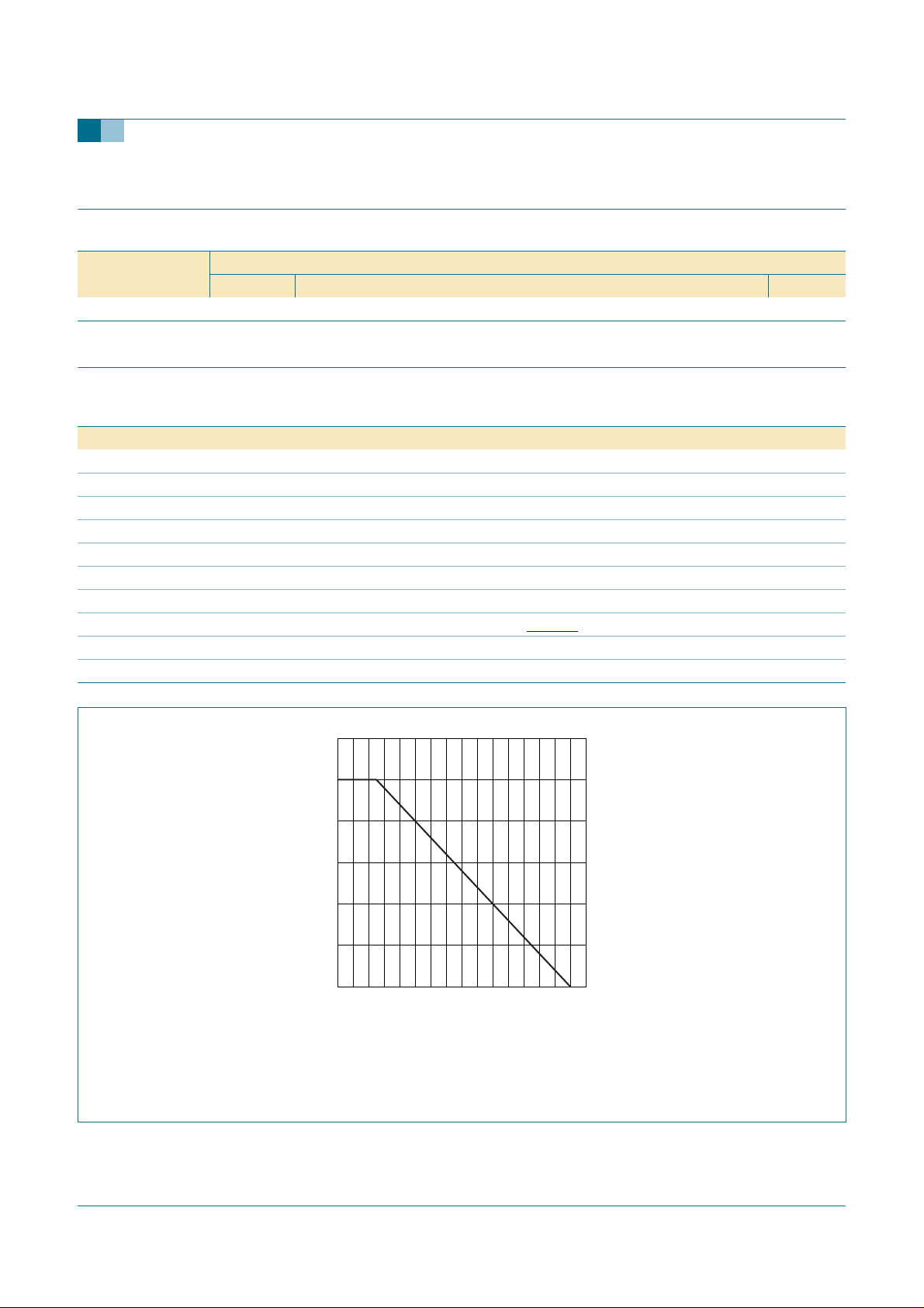
total power dissipation Tmb = ≤ 25 °C; see Figure 1 -80W
storage temperature −65 +150 °C
junction temperature - 150 °C
120
P
der
(%)
80
40
0
0 16012040 80
P
P
%()
der
tot
------------------------ -
P
tot 25 °C()
100%×=
001aab993
Tmb (°C)
Fig 1. Normalized total power dissipation as a function of mounting base temperature
9397 750 14196 © Koninklijke Philips Electronics N.V. 2004. All rights reserved.
Product data sheet Rev. 01 — 14 December 2004 2 of 12
Page 3
Philips Semiconductors
BUJ105AD
Silicon diffused power transistor
5. Thermal characteristics
Table 4: Thermal characteristics
Symbol Parameter Conditions Min Typ Max Unit
R
th(j-mb)
R
th(j-a)
[1] Device mounted on a printed-circuit board; minimum footprint
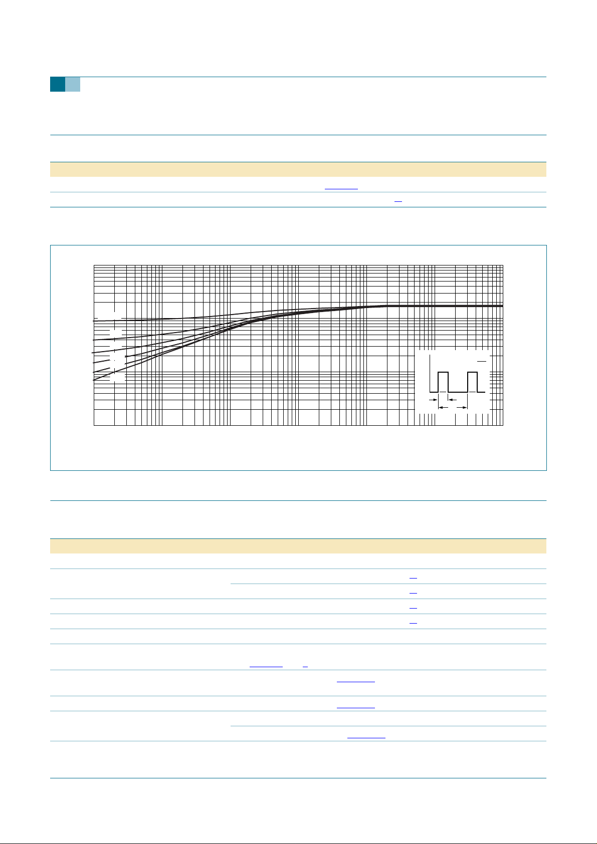
thermal resistance from junction to mounting base see Figure 2 - - 1.56 K/W
thermal resistance from junction to ambient
[1]
- 75 - K/W
001aab998
t
p
δ =
T
p
T
t
tp (s)
Z
th(j-mb)
(K/W)
10
δ = 0.5
1
0.2
0.1
0.05
0.02
−1
10
10
0.01
−2
−5
10
−4
10
−3
10
−2
10
−1
P
tot
t
11010
Fig 2. Transient thermal impedance from junction to mounting base as a function of pulse duration
6. Characteristics
Table 5: Characteristics
Tmb = 25°C; unless otherwise specified.
Symbol Parameter Conditions Min Typ Max Unit
Static characteristics
I
CES
I
CBO
I
CEO
I
EBO
V
CEOsus
V
CEsat
V
BEsat
h
FE
h
FEsat
collector-emitter cut-off current VBE = 0 V; VCE = V
= 0 V; VCE = V
V
BE
collector-base cut-off current VBE = 0 V; VCE = V
collector-emitter cut-off current V
CEO
= V
CEOMmax
CESMmax
CESMmax
CESMmax
= 400 V
; Tj= 125 °C
emitter-base cut-off current VEB = 9 V; IC = 0 A - - 1 mA
collector-emitter sustaining
voltage
collector-emitter saturation
IB = 0 A; IC = 10 mA; L = 25 mH;
see
Figure 3 and 4
IC = 4.0 A; IB = 0.8 A; see Figure 11 - 0.3 1.0 V
voltage
base-emitter saturation voltage IC = 4.0 A; IB = 0.8 A; see Figure 12 - 1.0 1.5 V
DC current gain IC = 1 mA; VCE = 5 V 10 14 34
= 500 mA; VCE = 5 V; see Figure 10 13 23 36
I
C
DC saturation current gain IC = 4.0 A; VCE = 5 V 8 11 15
[1]
- - 0.2 mA
[1]
- - 0.5 mA
[1]
- - 0.2 mA
[1]
- - 0.1 mA
400 - - V
9397 750 14196 © Koninklijke Philips Electronics N.V. 2004. All rights reserved.
Product data sheet Rev. 01 — 14 December 2004 3 of 12
Page 4
Philips Semiconductors
BUJ105AD
Silicon diffused power transistor
Table 5: Characteristics
…continued
Tmb = 25°C; unless otherwise specified.
Symbol Parameter Conditions Min Typ Max Unit
Dynamic characteristics
Switching times (resistive load); see
t
on
t
stg
t
f
turn-on time I
storage time - 1.8 2.5 µs
fall time - 0.3 0.5 µs
Switching times (inductive load); see
t
stg
t
f
storage time I
fall time - 2050ns
Switching times (inductive load); see
t
stg
t
f
[1] Measured with half sine-wave voltage (curve tracer).
storage time I
fall time - 25 100 ns
Figure 5 and 6
Figure 7 and 8
Figure 7 and 8
50 V
100 Ω to 200 Ω
= 5 A; I
V
V
Con
Con
BB
Con
BB
= 5 A; I
= 5 A; I
Bon
Bon
= −5V
Bon
= −5 V; Tj= 100 °C
= −I
= 1 A; RL=75Ω - 0.65 1 µs
Boff
= 1 A; LB=1µH;
= 1 A; LB = 1 µH;
I
C
(mA)
- 1.2 1.7 µs
- 1.4 1.9 µs
horizontal
oscilloscope
vertical
6 V
1 Ω300 Ω
30 Hz to 60 Hz
001aab987
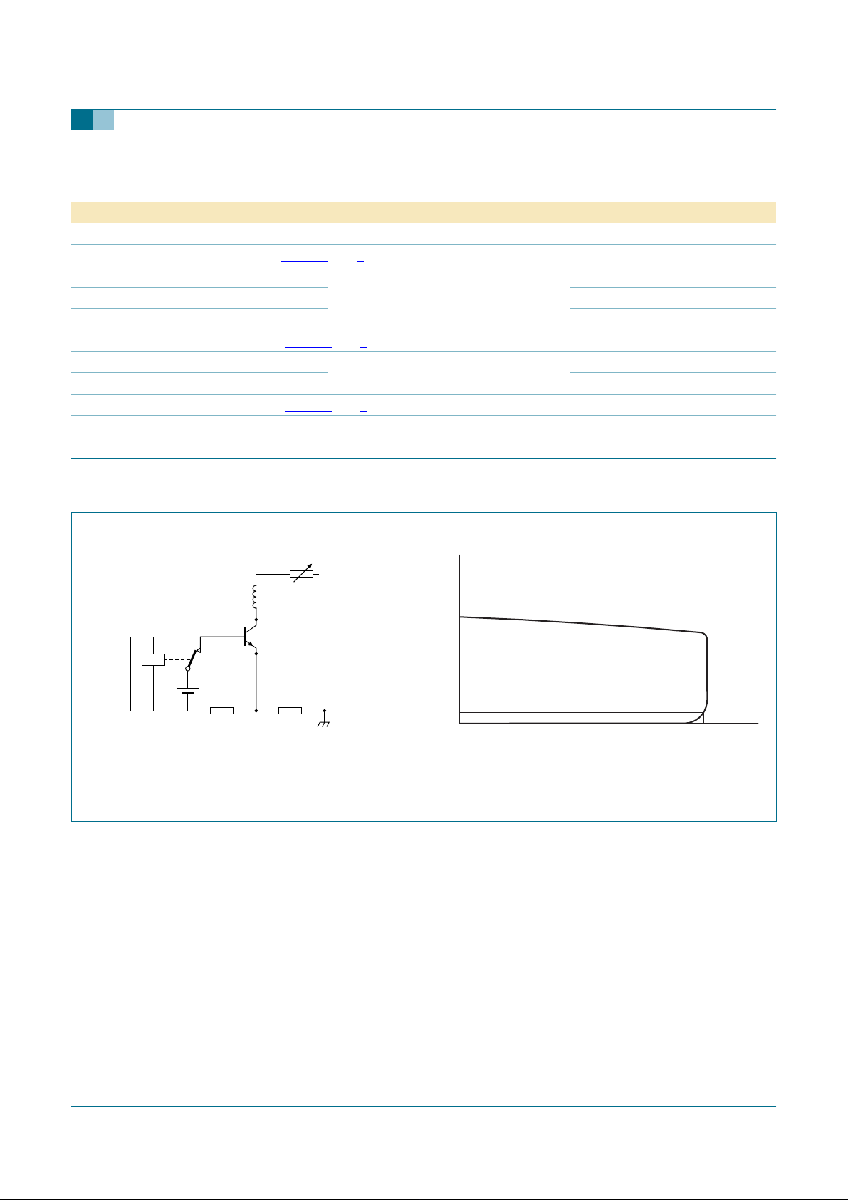
Fig 3. Test circuit for collector-emitter sustaining
voltage
250
100
10
0
min
V
CEOsus
001aab988
Fig 4. Oscilloscope display for collector-emitter
sustaining voltage test waveform
VCE (V)
9397 750 14196 © Koninklijke Philips Electronics N.V. 2004. All rights reserved.
Product data sheet Rev. 01 — 14 December 2004 4 of 12
Page 5
Philips Semiconductors
BUJ105AD
Silicon diffused power transistor
I
C
V
CC
R
L
V
IM
0
t
p
T
R
B
DUT
001aab989
90 %
t
I
B
t
on
stg
t
off
I
Bon
10 %
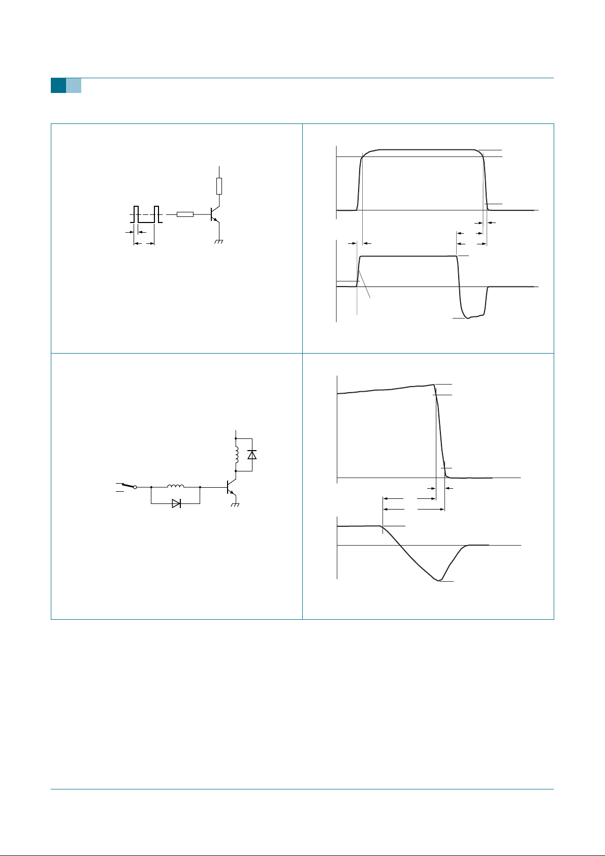
VIM = −6 V to +8 V; VCC = 250 V; tp = 20 µs;
δ =tp/T = 0.01.
RB and RL calculated from I
requirements.
Con
and I
Bon
tr ≤ 30 ns
−I
Boff
Fig 5. Test circuit for resistive load switching Fig 6. Switching times waveforms for resistive load
I
Con
90 %
10 %
t
f
001aab990
t
t
I
C
I
Con
90 %
V
CC
L
C
10 %
L
I
V
Bon
BB
B
DUT
001aab991
t
t
stg
t
I
off
Bon
I
B
f
t
t
−I
Boff
VCC = 300 V; VBB = −5 V; LC = 200 µH; LB = 1 µH.
001aab992
Fig 7. Test circuit for inductive load switching Fig 8. Switching times waveforms for inductive load
9397 750 14196 © Koninklijke Philips Electronics N.V. 2004. All rights reserved.
Product data sheet Rev. 01 — 14 December 2004 5 of 12
Page 6
Philips Semiconductors
BUJ105AD
Silicon diffused power transistor
001aac045
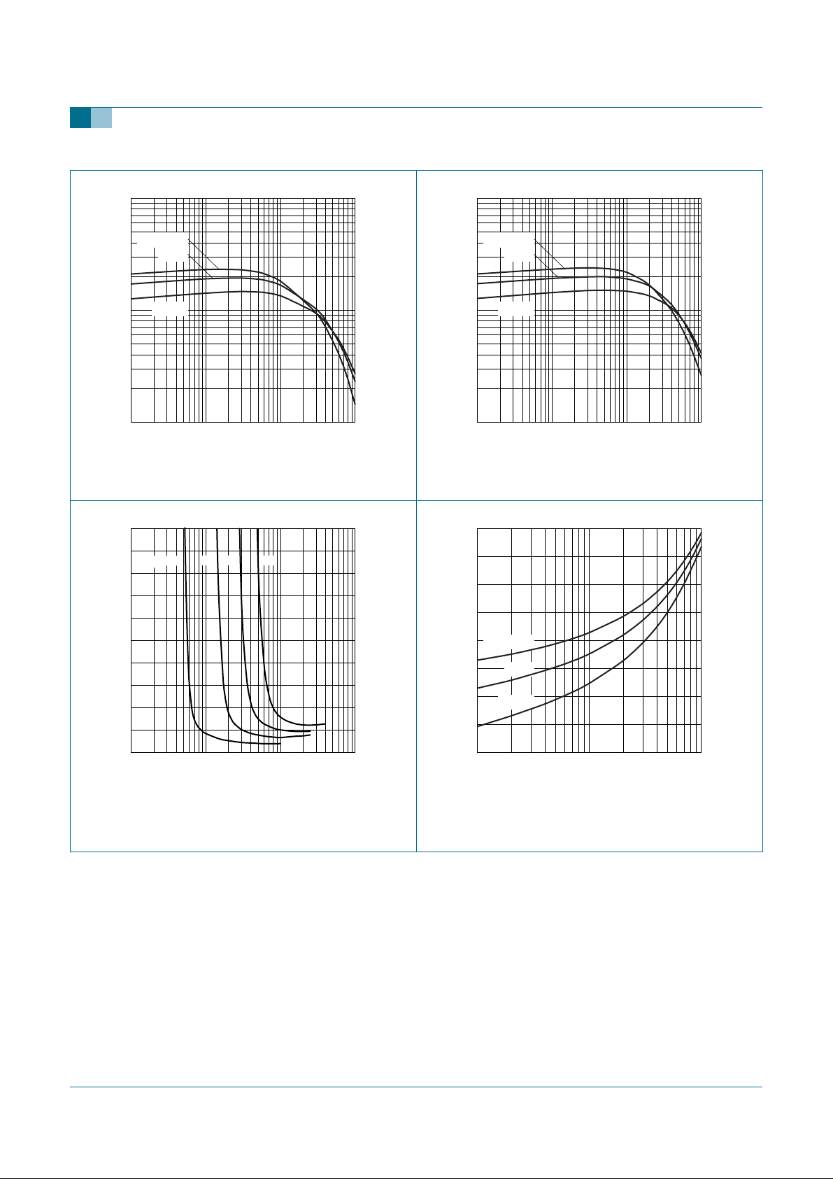
IC (A)
10110
h
10
FE
2
10
1
10
Tj = 100 °C
25 °C
−40 °C
−2
−1
Fig 9. DC current gain as a function of collector
current; typical values at V
2.0
V
CEsat
(V)
IC = 1 A 2 A 3 A 4 A
1.6
CE
= 1 V
001aab995
001aac046
IC (A)
10110
h
10
FE
10
2
Tj = 100 °C
1
−2
10
25 °C
−40 °C
−1
Fig 10. DC current gain as a function of collector
current; typical values at VCE = 5 V
001aac047
V
1.3
BEsat
(V)
1.1
1.2
0.8
0.4
0
−2
10
−1
IB (A)
10110
Tj = 25 °C. IC/IB = 4.
Fig 11. Collector-emitter saturation voltage as a
function of base current; typical values
0.9
Tj = −40 °C
25 °C
0.7
0.5
100 °C
−1
10
IC (A)
101
Fig 12. Base-emitter saturation voltage asa function of
collector current; typical values
9397 750 14196 © Koninklijke Philips Electronics N.V. 2004. All rights reserved.
Product data sheet Rev. 01 — 14 December 2004 6 of 12
Page 7
Philips Semiconductors
BUJ105AD
Silicon diffused power transistor
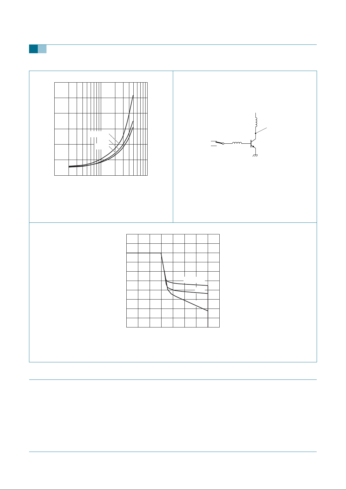
I
C
001aac048
(A)
101
V
0.6
CEsat
(V)
0.4
0.2
Tj = 100 °C
25 °C
−40 °C
0
−1
10
IC/IB = 4. V
Fig 13. Collector-emitter saturation voltage as a
function of collector current; typical values
10
I
C
(A)
8
V
CC
L
C
V
CEclamp
probe point
L
I
Bon
V
BB
< 700 V; VCC= 150 V; VBB= −5V,−3 V and
CEclamp
B
DUT
001aab999
−1 V; LB = 1 µH; LC = 200 µH.
Fig 14. Test circuit for reverse bias safe operating area
001aac049
Tj < T
j(max)
.
Fig 15. Reverse bias safe operating area
7. Package information
Epoxy meets requirements of UL94 V-0 at1⁄8 inch.
6
4
2
0
0 800600200 400
VBB = −5 V
−3 V
−1 V
V
CEclamp
(V)
9397 750 14196 © Koninklijke Philips Electronics N.V. 2004. All rights reserved.
Product data sheet Rev. 01 — 14 December 2004 7 of 12
Page 8
Philips Semiconductors
8. Package outline
BUJ105AD
Silicon diffused power transistor
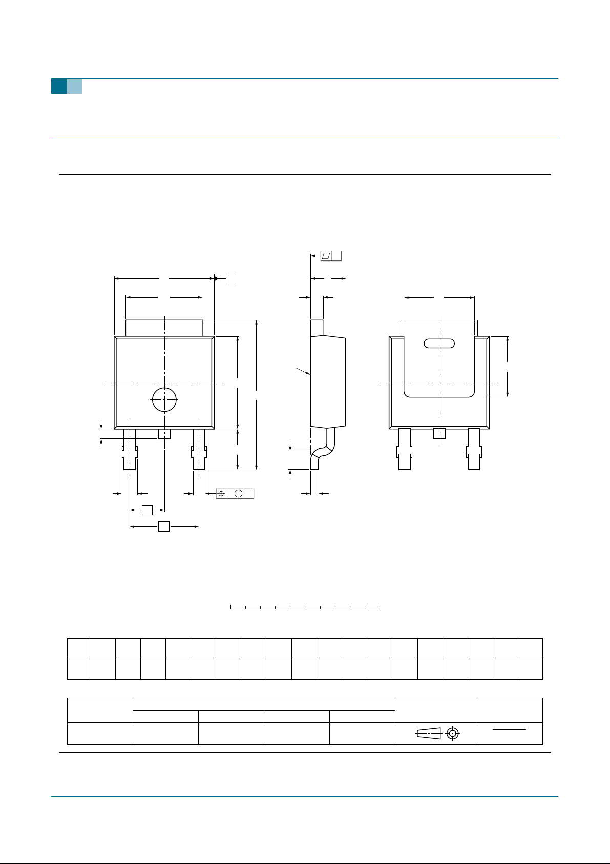
Plastic single-ended surface mounted package (D-PAK); 3 leads (one lead cropped)
y
E
b
2
L
2
2
13
A
mounting
base
D
1
H
D
L
L
1
A
A
1
SOT428
E
1
D
2
b
1
e
DIMENSIONS (mm are the original dimensions)
UNIT
mm
OUTLINE
VERSION
SOT428 SC-63
A
Ab
1
0.93
2.38
2.22
0.73
0.89
0.71
b
e
1
b
bcD
1.1
0.9
IEC JEDEC JEITA
2
1
5.46
5.00
Fig 16. Package outline SOT428 (SC-63)
M
wA
0 5 10 mm
D
2
1
min
0.56
6.22
5.98
4.0
0.20
REFERENCES
TO-252
c
scale
E
1
Ee
min
6.73
4.45
6.47
2.285 4.57
0.2
y
max
0.2
L
e
H
1
D
10.4
2.95
9.6
2.55
EUROPEAN
PROJECTION
1
Lw
min
0.5
L
2
0.9
0.5
ISSUE DATE
01-12-11
04-10-14
9397 750 14196 © Koninklijke Philips Electronics N.V. 2004. All rights reserved.
Product data sheet Rev. 01 — 14 December 2004 8 of 12
Page 9
Philips Semiconductors
9. Mounting
BUJ105AD
Silicon diffused power transistor
7.0
7.0
2.15
2.5
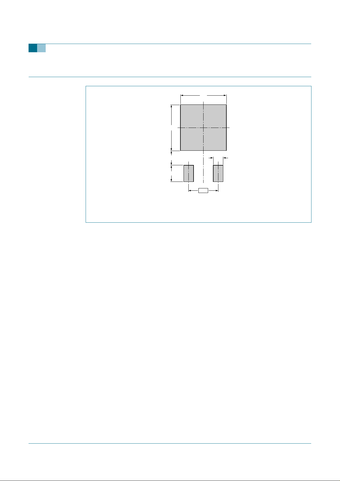
Dimensions in mm.
1.5
4.57
001aab021
Fig 17. SOT428 soldering pattern for surface mounting
9397 750 14196 © Koninklijke Philips Electronics N.V. 2004. All rights reserved.
Product data sheet Rev. 01 — 14 December 2004 9 of 12
Page 10

Philips Semiconductors
Silicon diffused power transistor
BUJ105AD
10. Revision history
Table 6: Revision history
Document ID Release date Data sheet status Change notice Doc. number Supersedes
BUJ105AD_1 20041214 Product data sheet - 9397 750 14196 -
9397 750 14196 © Koninklijke Philips Electronics N.V. 2004. All rights reserved.
Product data sheet Rev. 01 — 14 December 2004 10 of 12
Page 11

Philips Semiconductors
11. Data sheet status
BUJ105AD
Silicon diffused power transistor
Level Data sheet status
I Objective data Development This data sheet contains data from the objective specification for product development. Philips
II Preliminary data Qualification This data sheet contains datafromthe preliminary specification. Supplementary data will be published
III Product data Production This data sheet contains data from the product specification. Philips Semiconductors reserves the
[1] Please consult the most recently issued data sheet before initiating or completing a design.
[2] The product status of the device(s) described in this data sheet may have changed since this data sheet was published. The latest information is available on the Internet at
URL http://www.semiconductors.philips.com.
[3] For data sheets describing multiple type numbers, the highest-level product status determines the data sheet status.
[1]
Product status
12. Definitions
Short-form specification — The data in a short-form specification is
extracted from a full data sheet with the same type number and title. For
detailed information see the relevant data sheet or data handbook.
Limiting values definition — Limiting values given are in accordance with
the Absolute Maximum Rating System (IEC 60134). Stress above one or
more of the limiting values may cause permanent damage to the device.
These are stress ratings only and operation of the device at these or at any
other conditions above those given in the Characteristics sections of the
specification is not implied. Exposure to limiting values for extended periods
may affect device reliability.
Application information — Applications that are described herein for any
of these products are for illustrative purposes only. Philips Semiconductors
make no representation or warranty that such applications will be suitable for
the specified use without further testing or modification.
[2] [3]
Definition
Semiconductors reserves the right to change the specification in any manner without notice.
at a later date. Philips Semiconductors reserves the right to change the specification without notice, in
order to improve the design and supply the best possible product.
right to make changes at any time in order to improve the design, manufacturing and supply. Relevant
changes will be communicated via a Customer Product/Process Change Notification (CPCN).
13. Disclaimers
Life support — These products are not designed for use in life support
appliances, devices, or systems where malfunction of these products can
reasonably be expected to result in personal injury. Philips Semiconductors
customers using or selling these products for use in such applications do so
at their own risk and agree to fully indemnify Philips Semiconductors for any
damages resulting from such application.
Right to make changes — Philips Semiconductors reserves the right to
make changes in the products - including circuits, standard cells, and/or
software - described or contained herein in order to improve design and/or
performance. When the product is in full production (status ‘Production’),
relevant changes will be communicated via a Customer Product/Process
Change Notification (CPCN). Philips Semiconductors assumes no
responsibility or liability for the use of any of these products, conveys no
license or title under any patent, copyright, or mask work right to these
products, andmakes no representations or warrantiesthat these products are
free from patent, copyright,or mask work right infringement, unless otherwise
specified.
14. Contact information
For additional information, please visit: http://www.semiconductors.philips.com
For sales office addresses, send an email to: [email protected]
9397 750 14196 © Koninklijke Philips Electronics N.V. 2004. All rights reserved.
Product data sheet Rev. 01 — 14 December 2004 11 of 12
Page 12

Philips Semiconductors
15. Contents
1 Product profile . . . . . . . . . . . . . . . . . . . . . . . . . . 1
1.1 General description. . . . . . . . . . . . . . . . . . . . . . 1
1.2 Features . . . . . . . . . . . . . . . . . . . . . . . . . . . . . . 1
1.3 Applications . . . . . . . . . . . . . . . . . . . . . . . . . . . 1
1.4 Quick reference data. . . . . . . . . . . . . . . . . . . . . 1
2 Pinning information. . . . . . . . . . . . . . . . . . . . . . 1
3 Ordering information. . . . . . . . . . . . . . . . . . . . . 2
4 Limiting values. . . . . . . . . . . . . . . . . . . . . . . . . . 2
5 Thermal characteristics. . . . . . . . . . . . . . . . . . . 3
6 Characteristics. . . . . . . . . . . . . . . . . . . . . . . . . . 3
7 Package information . . . . . . . . . . . . . . . . . . . . . 7
8 Package outline . . . . . . . . . . . . . . . . . . . . . . . . . 8
9 Mounting. . . . . . . . . . . . . . . . . . . . . . . . . . . . . . . 9
10 Revision history. . . . . . . . . . . . . . . . . . . . . . . . 10
11 Data sheet status. . . . . . . . . . . . . . . . . . . . . . . 11
12 Definitions . . . . . . . . . . . . . . . . . . . . . . . . . . . . 11
13 Disclaimers. . . . . . . . . . . . . . . . . . . . . . . . . . . . 11
14 Contact information . . . . . . . . . . . . . . . . . . . . 11
BUJ105AD
Silicon diffused power transistor
© Koninklijke Philips Electronics N.V. 2004
All rights are reserved. Reproduction in whole or in part is prohibited without the prior
written consent of the copyright owner. The information presented in this document does
not form part of any quotation or contract, is believed to be accurate and reliable and may
be changed without notice. No liability will be accepted by the publisher for any
consequence of its use. Publication thereof does not convey nor imply any license under
patent- or other industrial or intellectual property rights.
Published in The Netherlands
Date of release: 14 December 2004
Document number: 9397 750 14196
 Loading...