

Page 1

Bluetooth QuickStart Kit Version 1.0 - User’s Guide
Copyright 2004-2005 © Embedded Artists AB
Bluetooth QuickStart Kit
User’s Guide
A Quick Way to Start Using and Integrate
Bluetooth in YOUR Application…
Builds on InfraBed™ technology
EA2-USG-0402 Rev A
Page 2

Bluetooth QuickStart Kit Version 1.0 - User’s Guide Page 2
Embedded Artists AB
Friisgatan 33
SE-214 21 Malmö
Sweden
info@EmbeddedArtists.com
http://www.EmbeddedArtists.com
Copyright 2004-2005 © Embedded Artists AB. All rights reserved.
No part of this publication may be reproduced, transmitted, transcribed, stored in a retrieval
system, or translated into any language or computer language, in any form or by any means,
electronic, mechanical, magnetic, optical, chemical, manual or otherwise, without the prior
written permission of Embedded Artists AB.
Disclaimer
Embedded Artists AB makes no representation or warranties with respect to the contents
hereof and specifically disclaim any implied warranties or merchantability or fitness for any
particular purpose. Information in this publication is subject to change without notice and
does not represent a commitment on the part of Embedded Artists AB.
Feedback
We appreciate any feedback you may have for improvements on this document. Please send
your comments to support@EmbeddedArtists.com
.
Trademarks
InfraBed and ESIC are trademarks of Embedded Artists AB. All other brand and product
names mentioned herein are trademarks, services marks, registered trademarks, or registered
service marks of their respective owners and should be treated as such.
Copyright 2004-2005 © Embedded Artists AB
Page 3

Bluetooth QuickStart Kit Version 1.0 - User’s Guide Page 3
Table of Contents
1.1 Contents ......................................................................................... 4
1.2 Using Bluetooth QuickStart Kit in Products................................ 4
1.2.1 Design and Production Services ................................................... 5
1.3 Software License ........................................................................... 5
1.4 Product Registration ..................................................................... 5
1.5 Other QuickStart Boards and Kits................................................ 5
2.1 Software Platform .......................................................................... 6
2.2 Features.......................................................................................... 6
2.3 Typical Usage................................................................................. 7
3.1 Typical Industrial Bluetooth Use-Cases..................................... 10
3.2 Remote Access ............................................................................ 10
3.3 Remote Control ............................................................................ 11
3.4 Remote Diagnostics .................................................................... 11
3.5 Local Service................................................................................ 12
3.6 Bluetooth Profiles ........................................................................ 13
3.6.1 Serial Port Profile ........................................................................ 13
3.6.2 LAN Access Profile ..................................................................... 13
3.7 connectBlue’s Modules............................................................... 14
4.1 File Structure................................................................................ 15
4.2 Program Development................................................................. 16
4.2.1 InfraBed ...................................................................................... 17
4.2.2 IAR Embedded Workbench......................................................... 17
4.2.3 Keil uVision ................................................................................. 17
4.3 Program Download ...................................................................... 17
4.3.1 Philips LPC2000 Flash Utility ...................................................... 18
4.3.2 LPC21ISP ................................................................................... 18
5.1 Schematic ..................................................................................... 20
5.2 Board Interfaces........................................................................... 22
5.3 Bluetooth Modules....................................................................... 24
5.4 Board Jumpers............................................................................. 25
5.5 Board Measurements .................................................................. 27
Copyright 2004-2005 © Embedded Artists AB
Page 4

Bluetooth QuickStart Kit Version 1.0 - User’s Guide Page 4
1 Introduction
Thank you for buying Embedded Artists’ Bluetooth QuickStart Kit based on the LPC2106
ARM7™ microcontroller from Philips and cb-OEMSPA-13i industrial Bluetooth module
from connectBlue.
The Bluetooth QuickStart Kit contains a pre-designed platform, both hardware and software,
with all necessary infrastructure functionality for using Bluetooth in industrial applications.
The kit allows you to quickly evaluate the applicability of Bluetooth in YOUR application.
Extensive documentation is included in order to lower the threshold of start using the kit
even further. You can start to develop and include your own application on day 1.
The LPC2106 microcontroller from Philips is used on the board. It is part of Philips new
ARM7TDMI-based family of high-performance microcontrollers.
This document is a User’s Guide that describes the Bluetooth Quickstart Kit with
accompanying software and program development tools. Amongst other, the document
contains information about the included software and a description on how to develop and
add your own application. Also, electrical and mechanical information about the board is
included.
1.1 Contents
The box received when ordering the Bluetooth QuickStart Kit contains the following:
• One Bluetooth QuickStart Board including one cB-OEMSPA-13i Bluetooth module
from connectBlue.
• One 64 Mbyte (or larger) SD memory card.
• One CD-ROM which includes all necessary software to start developing your
application program. It contains complete as well as evaluation versions of different
development environments along with a lot of sample applications.
• One DC power supply, 5 volt 300 mA. Observe that the Bluetooth QuickStart Board
does not contain any reverse polarity protection. If voltage is applied with wrong
polarity, the board will likely be damaged. Also observe that 6.0 volt is the absolute
maximum voltage that can be applied without damaging the on-board voltage
regulator (TPS70251). Consult the TPS70251 datasheet for exact details.
Always use the included DC power supply to avoid possible damages.
• One serial extension cable, DB9-male to DB9-female (DB9M-DM9F), for
connecting the Bluetooth QuickStart Board to a PC.
In addition, you may want the following in order to start developing applications with the
Bluetooth QuickStart Board:
• An optional JTAG interface, for program development debugging.
Observe that a JTAG interface is not needed for downloading new programs into the
Bluetooth QuickStart Board. This can be done through the serial channel, but a JTAG
interface enables better control over the processor and better debug support.
1.2 Using Bluetooth QuickStart Kit in Products
The Bluetooth Quickstart Board is not primarily designed for use in volume productions. It
has been designed as a reference platform that illustrates how Bluetooth can be used and as
an experimentation platform. The board can be used for low-volume production. Low-cost
bulk packages (10, or more boards) exist. Contact Embedded Artists for OEM pricing issues.
Copyright 2004-2005 © Embedded Artists AB
Page 5

Bluetooth QuickStart Kit Version 1.0 - User’s Guide Page 5
Modifications to the design for OEM production can easily be done. Contact Embedded
Artists for further information about design and production services.
1.2.1 Design and Production Services
Embedded Artists provide design services for custom designs, either completely new or
modification to existing boards. Specific peripherals and/or I/O can easily be added to the
different designs, for example communication interfaces, specific analogue or digital I/O,
and power supplies. Embedded Artists has extensive experience in designing industrial
electronics in general, and specifically with Philips LPC2xxx microcontroller family.
• Prototype and low-volume production takes place in Sweden for best flexibility and
short lead times.
• High-volume production takes place in China for lowest possible cost.
1.3 Software License
The software platform is provided as a library. This library may only be used in conjunction
with the Bluetooth QuickStart Board, i.e., it may only run on a Bluetooth QuickStart Board.
Embedded Artists sells commercial licenses for the software platform (including source
code) that can run on any custom hardware. Please contact Embedded Artists for pricing
information about commercial licenses of the software platform.
1.4 Product Registration
The accompanying CD-ROM contains a lot of information and programs that will
QuickStart your program development. Observe that there may be newer versions of
different documents and programs available than the ones on the CD-ROM.
By registering as a customer of Embedded Artists and as a Bluetooth QuickStart Kit user you
will always have access to the latest information and new material (e.g., new sample
applications).
Registering is easy and done quickly.
1) Go to http://www.EmbeddedArtists.com, select Support and then Register.
2) Type in the products serial number (can be found on the Bluetooth QuickStart Board
or on the package carrying the board) along with your personal information.
1.5 Other QuickStart Boards and Kits
Visit Embedded Artists’ home page, www.EmbeddedArtists.com, for information about
other QuickStart boards / kits or contact your local distributor.
Copyright 2004-2005 © Embedded Artists AB
Page 6

Bluetooth QuickStart Kit Version 1.0 - User’s Guide Page 6
2 Bluetooth QuickStart Kit
This chapter provides a description of the Bluetooth QuickStart Kit; the platform (software
and hardware aspects), features, and typical usage.
2.1 Software Platform
The Bluetooth QuickStart Kit includes a pre-designed software platform that integrates a
mayor part of the needed infrastructure for advanced Bluetooth applications. By using the
platform you avoid the long and narrow “do-it-yourself” way when start using new
technology with all these typical activities:
• Researching (RTOS, Compiler/IDE, TCP/IP Stack, PPP Stack, Web Server, File
System)
• Hardware design (this is of course not part of the software platform, but an activity
that is typically also required if you don’t buy an off-the-shelf hardware board).
• Configuration (RTOS, Compiler/IDE, TCP/IP Stack, PPP Stack, Web Server, File
System, Board Support Package)
• Testing (hardware, each individual software component, integrating the platform)
Figure 1 below illustrates both the software and hardware side of the Bluetooth QuickStart
Kit platform. Many sample applications are included in the kit just to lower the threshold of
start using the kit and to quickly get you up-and-running. The green parts in the picture
illustrate the mayor software infrastructure functions.
Bluetooth QuickStart Platform
YOUR Application
+
Lots of Sample Applications
Web Server
FAT File
System
Pre-emptive Real-Time Operating System
YOUR
Hardware
Expansion
RS232
MMC/SD
Flash
Memory Card
TCP/IP
PPP
Bluetooth
Module from
connectBlue
Antenna
Figure 1 – Bluetooth QuickStart Platform
2.2 Features
The software features of Embedded Artists’ Bluetooth QuickStart Kit are:
• Contains a pre-designed software platform with all necessary infrastructure:
• Code delivered as a binary library
Copyright 2004-2005 © Embedded Artists AB
− RTOS, TCP/IP Stack, PPP Stack, Web Server, FAT File System, Registry
− Source code package also available as separate purchase.
Page 7

Bluetooth QuickStart Kit Version 1.0 - User’s Guide Page 7
• Software platform code base is easily ported and extended to other hardware,
including other processor families.
• Many sample applications included in order to lower the threshold to get you started.
• Complete development environment is included (compiler, linker, make, editor, etc.)
− Based on GCC.
− Other compilers also supported, like Keil and IAR.
• The user can easily add own applications and experiment with the technology.
− About 30 kbytes of FLASH available and about 10 kbyte of SRAM
The hardware features of Embedded Artists’ Bluetooth QuickStart Kit are:
• Built around the new LPC2106 from Philips (ARM7TDMI).
− 128 Kbyte program Flash and 64 Kbyte SRAM
− Processor pins available on an expansion connector for user hardware
expansion.
• cB-OEMSPA13i Bluetooth module from connectBlue included in kit.
− Also works with cB-OEMSPA13x (external antenna) and cB-OEMSPA33i/x
(100 meter version).
− Works with connectBlue’s Serial Port Adapter Wizard program
• Connector for MMC/SD memory card
• ESD/EMI protected RS232 channel available for connection with other systems or
debug printouts.
− Support for automatic program download over the serial channel.
2
• 32 kByte non-volatile parameter memory (256 Kbit I
C E2PROM)
• Standard 20 pos. ARM JTAG connector available for debug.
• Size: 108 x 58 mm
− Four mounting holes are 100 x 50 mm apart
• Power: 5VDC, <150mA
2.3 Typical Usage
The Bluetooth QuickStart Kit can be used to easily create advanced MMI (Man-MachineInterfaces) based on Internet technologies:
• Use the web server to expose information and parameters that can be controlled.
• Use the file system to store HTML files and picture files.
• Use the serial channel to communicate (expose information or control parameters)
• Access the system directly via a PDA, a laptop, or a Bluetooth LAN access point.
Figure 2 below illustrates how the Bluetooth QuickStart Board can be connected to any
embedded system and expose internal variables in this system, or alternatively controls
Copyright 2004-2005 © Embedded Artists AB
with ANY System.
Page 8

Bluetooth QuickStart Kit Version 1.0 - User’s Guide Page 8
internal parameters in the system. Communication with the (arbitrary) embedded system can
be done via the RS232 serial channel.
ANY System
Expose
Application
Control
Bluetooth
QuickStart Kit
PDA
Laptop
Stationary
Ethernet
WWW
Figure 2 – Typical Bluetooth QuickStart Application Scenario
In the scenario above, the Bluetooth QuickStart Board is used to create an advanced user
interface to the embedded system. It is also possible to embed a complete application into the
Bluetooth QuickStart Board. Relatively large applications can be added to the pre-designed
software platform and the hardware can be expanded with necessary I/O. Figure 3 below
illustrates this scenario.
Bluetooth
QuickStart Kit
ANY System
Application
PDA
Laptop
Stationary
Figure 3 – Integrating a Complete Application into the Bluetooth QuickStart Board
Ethernet
WWW
There is a trend towards more integrated system solutions, especially in industrial
applications. Driving factors are more cost effective solutions (in many cases also increased
performance) and better possibilities for surveillance, diagnostics, and maintenance. There
Copyright 2004-2005 © Embedded Artists AB
Page 9

Bluetooth QuickStart Kit Version 1.0 - User’s Guide Page 9
are many interesting business possibilities when integrating diagnostic functions in a system,
like better maintenance and a profitable after market. Remote administration and remote
control gives the prerequisites of lower working expenses, lower total system costs, and a
profitable after market.
The Bluetooth QuickStart Kit allows you to experiment and develop these kinds of
applications.
Copyright 2004-2005 © Embedded Artists AB
Page 10

Bluetooth QuickStart Kit Version 1.0 - User’s Guide Page 10
3 Bluetooth Use-Cases
This chapter provides a description of typical use-cases when using Bluetooth in industrial
applications.
3.1 Typical Industrial Bluetooth Use-Cases
There are basically two different use-cases for industrial Bluetooth applications:
• User Interface
In this case, Bluetooth is used to access a system wirelessly in order to control
different parameters and/or to retrieve information. A web server is used to create
the user interface and a standard web browser can be used to access the system.
• Machine-to-Machine Communication (M2M)
In this case, Bluetooth is used for communication between different (industrial)
systems. Standard TCP/IP communication is used to transfer information.
Alternatively, Bluetooth is used to create a simple serial cable replacement. The
Bluetooth modules from connectBlue have this feature built-in from start (i.e., the
serial cable replacement). The Bluetooth QuickStart Kit is used to create more
advanced applications based on TCP/IP communication.
A user interface can be viewed as the manual version of the automatic M2M communication.
An operator can basically perform all the operations manually that would otherwise take
place automatically.
The following sections will describe a couple of typical advanced industrial Bluetooth usecases, all of which can be built by using the Bluetooth QuickStart Kit. Motor applications are
used to illustrate the industrial function, but can of course be any industrial building
component.
3.2 Remote Access
Remote access of a system has many benefits:
• A more up-to-date view of the system is possible, even though the different parts of
the system may be far apart. Bluetooth support distances up to 100 meters. If a
longer distance is needed, some systems may connect directly to an Ethernet
network.
• General cost reduction since information can be accessed without physical presence
near the system.
Examples of remote access systems are different meter systems, like power meters and water
meters. The information is produced locally (at a remote location) and is more valuable in a
central place. Figure 4 below illustrates the remote access use-case.
Bluetooth or
direct access
Figure 4 – Remote Access Use-Case
Copyright 2004-2005 © Embedded Artists AB
Internet
Operator Stations
Read Status
Page 11

Bluetooth QuickStart Kit Version 1.0 - User’s Guide Page 11
3.3 Remote Control
Remote control is almost the same as remote access. The only difference is the direction of
the information. In remote access the information mainly flows from the remote system to
(typically) a central place. In remote control the information direction is the opposite; from
the central place to the remote system. A number of (typical) example applications are:
• Motor control, which can for example be a softstarter, power control (on/off),
adding remote I/O capabilities, and simple PLC functionality.
• Pumps, which is basically a motor system that must be controlled.
• Conveyors, which is also a motor system with many parameters to set.
• Ventilation systems, which can be advanced control systems with many parameters
to set and control.
• Device configuration, which is the general case of controlling a remote system.
Figure 5 below illustrates remote control of a motor, either via direct cabling or direct
Bluetooth access via a PDA or laptop.
Operator Stations
Start Motor
Internet
Bluetooth or
direct access
Wireless
PDA
Figure 5 – Remote Control Use-Case
There are many benefits when creating remote control systems:
• Of course, the ability to control remote control systems at remote locations
• Wireless control, sometimes as simple as serial cable replacement, but also more
advanced forms of communication.
• The possibility to control hazardous applications, which can for example be
dangerous to be physically close to the system (i.e., rotating or high-voltage).
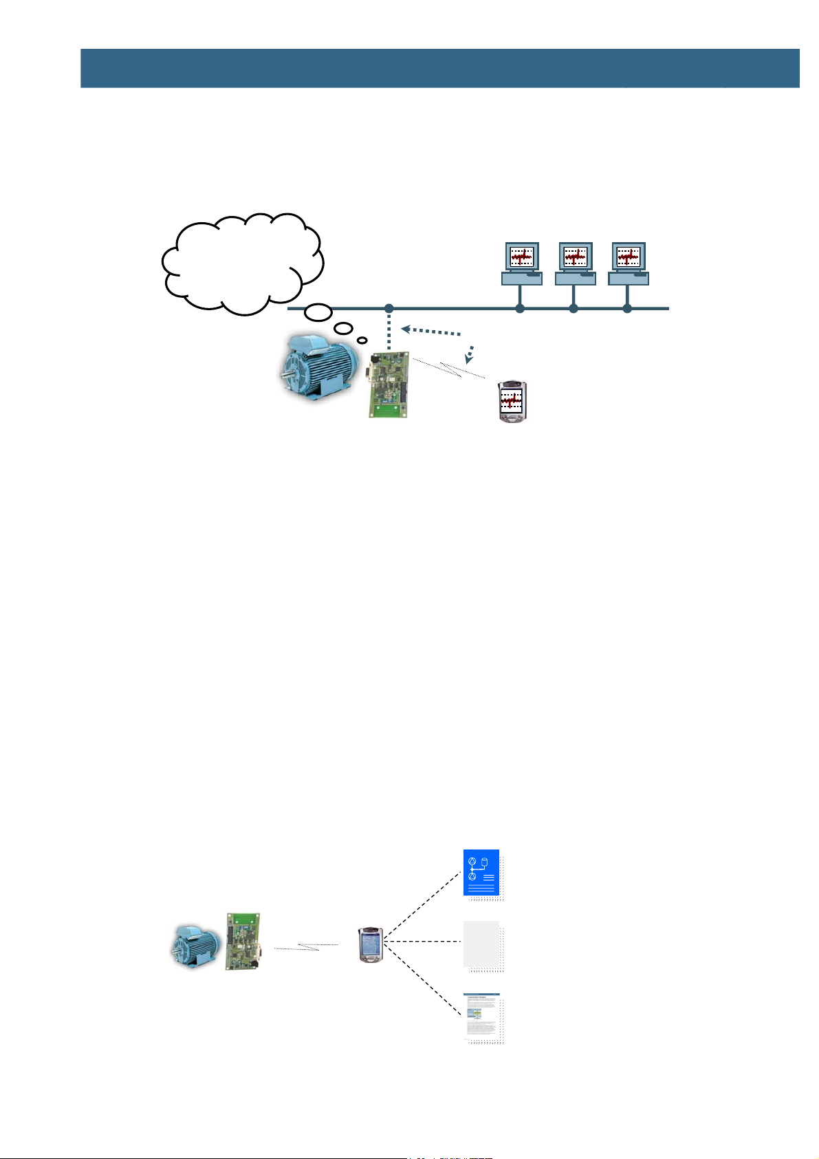
3.4 Remote Diagnostics
Remote diagnostics is an important application of remote access. An example application is
motor diagnostics that will serve as a reference application in this description. Examples of
analyses are:
• Bearing vibration analysis
• Voltage and current measurement
• Temperature measurement
• Counting number of start and stops
The information can either be locally analyzed or sent to a central location for further
processing. Decisions, like immediately stopping the motor, can be taken locally if the
Copyright 2004-2005 © Embedded Artists AB
Page 12
Bluetooth QuickStart Kit Version 1.0 - User’s Guide Page 12
decisions must be made quickly. Trends can be discovered when analyzing the data, for
example that a bearing is about to break down but will hold for another two months.
Maintenance can in such cases be planned in advance to minimize the operation costs.
Figure 6 below illustrates a typical system with motor diagnostics.
Operator Stations
Vibration too high.
Stopping motor!
Bluetooth or direct access
Wireless
PDA
Figure 6 – Remote Diagnostics Use-Case
The benefits of remote diagnostics are numerous:
• Lower maintenance cost
• Fewer unexpected system failures since maintenance can be planned in advance
• The prerequisite for Service Level Agreements (SLAs)
• The possibility for remote data logging
3.5 Local Service
Local service is a good example of how the web server functionality in the Bluetooth
QuickStart Board can be used. The system stores a number of relevant documents, such as:
• Service Logs
• Blueprints
• Datasheets
• User’s Manuals
The system can of course also be configured via the web server user interface. Figure 7
below illustrates the local service use-case.
Figure 7 – Local Service Use-Case
Copyright 2004-2005 © Embedded Artists AB
Service Log
[2003-12- 24]
[2004-01- 10]
[2004-02- 25]
Blueprint
Service Log
User’s Manual
Page 13

Bluetooth QuickStart Kit Version 1.0 - User’s Guide Page 13
A field engineer, or similar, can then easily access all relevant documents directly on site.
The system becomes more self-contained since all relevant documents “follow” the system.
The benefits are also in this case numerous:
• Easy local access to the system
• No need to physically connect to the system
• Manuals and logs are always available on the system
3.6 Bluetooth Profiles
What is a Bluetooth profile?
Well, it is basically the result of genuine engineering work. The profile concept is used to
minimize (perhaps not completely eliminate) the risk of interoperability problems between
different manufacturers' Bluetooth products. A number of user models describe different user
scenarios and roles, where Bluetooth performs the radio transmission. Different profiles have
been developed based in these use cases. A profile describes how to implement a specific
group of use cases. It also defines options in each protocol (in the Bluetooth protocol stack)
that are mandatory for the profile, as well as parameter ranges for each included protocol.
The profile protocols can be viewed as protocols placed on top of the basic Bluetooth
protocol stack. A profile can be described as a vertical slice through the protocol stack. Many
profiles build on each other. For example, the LAN Access profile requires the Serial Port
profile, as do the Dial-up Networking profile.
Every Bluetooth unit must support the Generic Access Profile, or GAP for short. It defines
many of the basic Bluetooth functions, such as device discovery, security, and name
discovery.
3.6.1 Serial Port Profile
There are a lot of profiles that have absolutely no use in industrial applications but rather
targeted for specific consumer applications, such as transferring pictures from a digital
camera, transferring data to a printer, and sending/receiving faxes. These profiles will not be
covered, but two profiles are worth mentioning. The first of them is the Serial Port Profile, or
SPP for short. It emulates a serial cable connection between two peer devices, or simply put,
transparently transfers a stream of byte from point A to point B and vice versa.
SPP has defined the roles DevA and DevB. DevA is the initiator of a connection, and DevB
is hence the recipient of a connection request. In order for a device to enable incoming
connections, the DevB role must be enabled in that specific device. It is possible to have
several parallel connections in a device, i.e. several instances of DevA and/or DevB. Figure
8 below illustrates the different SPP roles.
Connect
DevA
Client
Data transfer
DevB
Server
Figure 8 – Serial Port Profile Roles
3.6.2 LAN Access Profile
The second profile what we will have a closer look into is the LAN Access Profile, or LAP
for short. It allows a device to access a LAN (typically an Internet network) through a
gateway (actually a server). LAP has defined the roles LAN Access Point (LAP) and Data
Terminal (DT). The LAP acts like a gateway and provides the actual LAN access, and the
DT device uses the services provided by LAP. Figure 9 illustrates the roles. To enable
Copyright 2004-2005 © Embedded Artists AB
Page 14

Bluetooth QuickStart Kit Version 1.0 - User’s Guide Page 14
incoming connection requests to the LAN Access Profile, the LAP role must be enabled in
that specific device. It is possible to enable several instances of the LAP role in order to
allow several parallel connections through the LAP. A device must take the DT role in order
to connect to other devices supporting the LAP role.
The data transfer takes place over PPP and TCP/IP, which encapsulate the actual user data.
The LAN Access profile only provides a transparent serial channel, much like SPP. Only
PPP is dictated by the profile, but TCP/IP is almost always used on top of PPP.
Also observe that the LAN must not be an actual LAN (like Ethernet). It can also be a
simulated LAN, which is very application specific.
DT
Client
LAN Access Profile
Figure 9 – LAN Access Profile Roles
Connect
Data transfer
(PPP, TCP/IP, user data)
LAP
Server
LAN Access Profile
LAN
3.7 connectBlue’s Modules
The Bluetooth module (cB-OEMSPA-13i) from connectBlue that is used in the Bluetooth
QuickStart Kit can operate in one of several different profile modes:
• SPP server
The module waits for SPP clients to connect and establish transparent serial
channels. This mode is not used in the Bluetooth QuickStart Kit.
• SPP clients
The module tries to connect to SPP servers, in order to establish a transparent serial
channel. This mode is not used in the Bluetooth QuickStart Kit.
• LAN Access Server
This is the normal operating mode when using the Bluetooth QuickStart Kit. The
board behaves as a web server that can be accessed from LAN clients that connect
to the LAN server. The system waits for clients (i.e., web browsers) to connect.
There is no actual LAN that is accessed. Instead the TCP/IP stack and web server
on the board are accessed.
• LAN Access Client
Copyright 2004-2005 © Embedded Artists AB
This is an alternative operating mode when using the Bluetooth QuickStart Kit. In
this case, the system initiate connection requests (i.e., it is a client) to other LAN
access servers. These servers can be only web servers without any actual LAN
behind when, or they can be LAN access points. In the latter case, the servers act as
gateways between the Bluetooth world and (typically) a wired Ethernet world.
Page 15

Bluetooth QuickStart Kit Version 1.0 - User’s Guide Page 15
4 Compiling and Running Application
Programs
This chapter provides a description of how to develop, compile, and download applications
into the Bluetooth QuickStart Board.
4.1 File Structure
The pre-designed software platform is delivered as a library along with a number of header
files that declare the different API:s. See BApplication Program Interface (API) for a
detailed API description. The platform contains the following main infrastructure functions:
• Pre-emptive Real-Time Operating System (RTOS)
• TCP/IP protocol stack
• PPP protocol stack
• Web server
• File system, supporting MMC/SD memory cards. Supports FAT16.
• Registry, for non-volatile storage of parameters
The platform is place in a directory called QSPlatform. This directory contains two
important files; quickstart_vXYZ.a (which is the library of the platform) and
quickstart_vXYZ.h (which is the API definition). _vXYZ indicate the version of the
platform, and can for example be _v102 (meaning version 1.0.2). See Figure 10 below for
an illustration of the file structure.
QuickStartKit
Glue between platform and application
*.c
glue.c
Application Programmers Interface
API Definit ions
QSPlatform
Inner Subdirectories
Sample_xxx
Sample_yyy
Sample_zzz
*.h
quickstart_vXYZ.h
quickstart_vXYZ.a
Sample Applications
*.c
Source code that demonstrates different
*.h
functionality within the platform
Sample Applications
*.c
Source code that demonstrates different
*.h
functionality within the platform
Sample Applications
*.c
Source code that demonstrates different
*.h
functionality within the platform
Figure 10 – Bluetooth QuickStart Kit File Structure
A number of sample applications are included in the Bluetooth QuickStart Kit. These are
placed in the different sample_xxx subdirectories. It is recommended to study these
examples for a better understanding of the platform and how to create custom applications.
Each sample application typically contains one, or more, C-files implementing the
Copyright 2004-2005 © Embedded Artists AB
Your_application
*.c
Your Sample Application
*.h
Source code that implement your application
Page 16

Bluetooth QuickStart Kit Version 1.0 - User’s Guide Page 16
application and a makefile. The makefile contains directives of how to compile and link the
complete application. A typical makefile is listed in Figure 11 below.
/*
* Example makefile that creates a program called ‘mySampleApp’
*/
# name of the program
NAME = mySampleApp
PROJECT_ROOT = .
# Link program to RAM or ROM (possible values for RAMROM is RAM or ROM,
# if not specified = ROM)
RAMROM = ROM
# ELF-file contains debug information, or not
# (possible values for DEBUG are 0 or 1)
DEBUG = 1
# Optimization setting
# (-Os for small code size, -O2 for speed)
DBFLAGS = -Os
#Extra flags
EFLAGS = -mthumb-interwork
# Processes run in ARM or THUMB mode
# OBS. Do not change this setting. Instead, re-generate the operating system
TASK = THUMB
# subdirectories to recursively invoke make in
SUBDIRS =
# additional libraries to merge into this library
LIBS = ../quickstart/quickstart_vXYZ.a
# c-code files
CSRCS = ../glue.c \
mySampleApp.c
include program.mk
Figure 11 – Example Makefile
Name of final program.
Include the platform
library: quickstart.a
Always include glue.c
Also include all application files,
in this case: mySampleApp.c
A typical application (mySampleApp.c, in this case) includes the file glue.c (under the
file root) and includes quickstart_vXYZ.h whenever the platform API must be used.
The file glue.c contains a number of initialization functions and program hooks (can be
used for extending the functionality of the platform). Also, the library
quickstart_vXYZ.a is included in the final link stage.
4.2 Program Development
Three different application program development environments are supported:
• InfraBed from Embedded Artists
Embedded Artists unique configurable software generator contains a complete GCC
build environment for very easy program development. The current version of GCC
is 3.4.3. By installing InfraBed you will automatically also get a complete setup of
the build environment. This is the preferred way of developing and compiling
application programs.
• IAR Embedded Workbench
A complete development environment from IAR Systems, including an editor,
project manager, a complete compiler build environment, and a debugger. This
development environment must be bought separately from IAR.
Copyright 2004-2005 © Embedded Artists AB
Page 17

Bluetooth QuickStart Kit Version 1.0 - User’s Guide Page 17
• Keil uVision (DKARM version)
This is another complete development environment, but from Keil. It includes an
editor, project manager, a complete compiler build environment, and a debugger. An
evaluation version can be downloaded from Keils homepage. The DKARM-version
is based on the GCC compiler (currently version 3.3.1 of GCC). It is this version of
the compiler that can be used for application development.
4.2.1 InfraBed
Along with InfraBed, a complete build environment and program download exist for GCC.
The build environment is built around a bash script. This script sets up all necessary paths.
When installing InfraBed you will automatically get shortcuts to this bash script. A practical
feature is that there can be different scripts for different hardware platforms, for controlling
different hardware specific details of the platforms. There can also be many different
compilers (including different versions of the same compiler) without conflicting with each
other.
To build the application program, start a command prompt (the bash script) and type: make.
Depending on the make file content, either an executable program or a library will be
created. To also download the executable program, type: deploy instead of make. A
description about program downloading can be found in Section 4.3 .
A final note about the make file; make clean will erase all object file.
4.2.2 IAR Embedded Workbench
Consult the IAR Embedded Workbench documentation (after installation) for details about
how to get started.
4.2.3 Keil uVision
Consult the Keil uVision documentation (after installation) for details about how to get
started.
4.3 Program Download
When the application program has been written, compiled, and linked with the platform it is
time to download the program into the Bluetooth QuickStart Board. It is assumed that there
exists a HEX-file that represents the binary image of the complete program.
There are basically two ways of downloading a program into the LPC2106 microcontroller:
• ISP – In-System Programming
The LPC2106 microcontroller provides on-chip bootloader software that allows
programming of the internal flash memory over the serial channel. The bootloader is
activated by pulling port pin P0.14 low during reset of the microcontroller. The
Bluetooth QuickStart Board contains circuits for automatically controlling pin P0.14
and the reset signal over the RS232 channel. This allows the program download to
be fully automated.
Copyright 2004-2005 © Embedded Artists AB
o Philips provides a utility program for In-System Flash (ISP) programming
called LPC2000 Flash Utility.
o Alternatively, there is a program called LPC21ISP that can be used. Source
code is available. This program also provides a terminal functionality, which
can be very helpful when developing your application program. The same
serial channel that is used to download the program is typically also used for
printing out information from the running program. The program
immediately switch to terminal mode after program download and will
hence not miss any characters sent on the serial channel directly after
program start.
Page 18

Bluetooth QuickStart Kit Version 1.0 - User’s Guide Page 18
The installation files for both programs can be found on the accompanying CDROM.
• JTAG
For specific information about program download (i.e., Flash programming) with a
JTAG interface, consult the manual for the specific JTAG interface that is used (e.g.,
J-link from Segger, Ulink from Keil, or Wiggler from MacRaigor).
Set switch SW2 in the position that enables the automatic program download feature. After
program download, switch SW2 can be left in the “enable automatic bootloader” position or
changed into the “disable automatic bootloader” position, if needed. If, for example, the
system that is connected to the RS232 channel controls the RS232 signals DTR and/or RTS
during normal program execution, then it might be required that SW2 is placed in the
“disable automatic bootloader” position. Else the automatic bootloader may be
unintentionally activated.
4.3.1 Philips LPC2000 Flash Utility
Philips LPC2000 Flash Utility program looks like Figure 12 below.
Figure 12 – Philips LPC2000 Flash Utility Screenshot
Configure the dialog as shown above. The program will control the RS232 signals DTR and
RTS if the appropriate checkbox is checked, and hence provide fully automated program
download.
Test connection with the Bluetooth QuickStart Board by pressing the Read Device ID button.
The text fields for Part ID and Boot Loader ID will then contain uploaded information from
the microcontroller. Observe that the XTAL Freq. must be set to appropriate value. The
default mounted crystal frequency on the Bluetooth QuickStart Board is 14.7456 MHz. In
this case the value 14746 shall be written in the text box. If no connection can be established
test with a low Baud Rate, for example 1200 bps. Also verify that the correct COM-port has
been selected (under Connected to Port).
Select the HEX file to be downloaded and then press the Upload to Flash button.
The downloaded program will immediately start after the download (i.e. the Upload to Flash
operation is ready) is the option Execute Code after Upload is checked.
4.3.2 LPC21ISP
The LPC21ISP program is made publicly available by Martin Maurer. Source code is also
available at: http://engelschall.com/~martin/lpc21xx/isp/index.html. Figure 13 below shows
the command syntax for the program.
Copyright 2004-2005 © Embedded Artists AB
Page 19

Bluetooth QuickStart Kit Version 1.0 - User’s Guide Page 19
Figure 13 – LPC21ISP Portable Command Line ISP Screenshot
A typical program download sequence may look like in Figure 14 below. As seen, the first
part is the actual program download phase. Then this is done, the program switches to being
a terminal (the second part) and the messages from the application program are displayed. It
also sends anything typed on the keyboard back to the Bluetooth QuickStart Board. As seen
the program ends when ESC is pressed.
Program
Download
Phase
Terminal
Figure 14 – LPC21ISP Portable Command Line ISP Download Screenshot
Phase
Observe that the binary version 1.22 of the program will not work directly without a change
in the reset timeout (when the program tries to synchronize to the Bluetooth QuickStart
Board). The timeout must be increased to at least 200 ms.
LPC21ISP is automatically invoked when deploy is typed in the command prompt (the
bash script from InfraBed).
Copyright 2004-2005 © Embedded Artists AB
Page 20

Bluetooth QuickStart Kit Version 1.0 - User’s Guide Page 20
5 Schematic and Measurements
The chapter describes the Bluetooth QuickStart Kit board schematic and measurements.
5.1 Schematic
The Bluetooth QuickStart Kit board schematic is drawn in Figure 15 and Figure 16 below.
Figure 15 – Bluetooth QuickStart Board Schematic Drawing Page 1
Copyright 2004-2005 © Embedded Artists AB
Page 21

Bluetooth QuickStart Kit Version 1.0 - User’s Guide Page 21
Figure 16 – Bluetooth QuickStart Board Schematic Drawing Page 2
Copyright 2004-2005 © Embedded Artists AB
Page 22

Bluetooth QuickStart Kit Version 1.0 - User’s Guide Page 22
(p
)
m
(
)
5.2 Board Interfaces
The Bluetooth QuickStart Kit board has a number of external interfaces as illustrated in
Figure 17 below.
Bluetooth
module
Status indicating
RGB LEDs
MMC/SD memory
card connector
bottom side
Female
9-pos DSUB
Power
jack
2.1 m
Bluetooth factory
JTAG connector
for LPC2106
Expansion connector
Figure 17 – Bluetooth QuickStart Board Interface Description
Table 1 below explains each board interface in more detail.
Female 9-pos DSUB
A standard RS232 channel with
ESD/EMI protection. Normally
connected to a PC or an embedded
system.
Connector is used for:
1. Program download
2. Terminal printouts for
application program
Pin 2 = transmit data (output)
Pin 3 = receive data (input)
Pin 4 = DTR (input) for controlling automatic
program download
Pin 5 = ground
Pin 7 = RTS (input) for controlling automatic
program download
Pin 8 = CTS (output)
development debugging
Reset
LED
Reset
button
in #1
Copyright 2004-2005 © Embedded Artists AB
3. Connection with ANY embedded
system, in order to transfer data
between the system and the
Bluetooth QuickStart Board.
Page 23

Bluetooth QuickStart Kit Version 1.0 - User’s Guide Page 23
Power jack
4-6 V DC, at least 150 mA.
The power input is protected against
reverse polarity, but the board may
still be damaged if reverse polarity is
applied. Also, never exceed +6V DC
because the on-board voltage
regulator will then be damaged.
Always use the power supply that
comes with the Bluetooth QuickStart
Kit.
Reset LED
Reset is typically active 120 mS.
Reset button
Manual reset button that will
generate a 120 mS reset pulse.
Center pin = Ground
Outer shield = +4-6V DC
The LED lights when reset is active, i.e., the reset
signal is low.
Expansion connector
All processor pins are available at the
expansion connector. Many pins are
used by the Bluetooth QuickStart Kit
platform, but some are still available.
Consult the LPC2106 datasheet for
detailed signal description.
JTAG connector
JTAG connector for program
download and program debugging.
Consult the LPC2106 datasheet and
ARM JTAG description for details
about all signals and functionality.
Bluetooth module
This is the Bluetooth module from
connectBlue. Consult the modules
datasheet for detailed functional and
signal description.
See schematic (Figure 15 and Figure 16) for signal
positions.
Standard 20 pos. ARM JTAG connector.
How the connector is connected to the LPC2106
processor pins is shown in the schematic, see
Figure 15.
See cB-OEMSPA-13i datasheet for signal
description
Bluetooth factory reset switch
This push-button is connected
directly to the Bluetooth module and
is part of the factory reset
functionality. Consult the cB-
Copyright 2004-2005 © Embedded Artists AB
Page 24

Bluetooth QuickStart Kit Version 1.0 - User’s Guide Page 24
OEMSPA-13i datasheet for details
about functionality.
This push-button should normally
never be used, and it is only active
during power-up of the Bluetooth
module.
RGB LED #1
This RGB LED is controlled from
the Bluetooth module and indicates
current status.
Green = Module is OK
Orange = Module is in AT-command mode
Blue = A connection is active
Flashing Blue = Data is transferred over the active
connection
Red = Reset or illegal AT-commands
received
RGB LED #2
This RGB LED is controlled by the
application program and can be used
for program debugging or showing
application status.
Table 1 – Board Interfaces
5.3 Bluetooth Modules
The Bluetooth connector (J9 in the schematic) supports four different versions in the OEM
Serial Port Adapter family from connectBlue, as listed in Table 2 below.
Name Size Bluetooth Data
OEMSPA13i 23 x 36 mm Class 2 / 0 dBm with internal antenna
OEMSPA13x 23 x 36 mm Class 2 / 0 dBm with external antenna
OEMSPA33i 40 x 42 mm Class 1 / 20 dBm with internal antenna
OEMSPA33x 40 x 42 mm Class 1 / 20 dBm with external antenna
Table 2 – OEM Serial Port Adapters
Copyright 2004-2005 © Embedded Artists AB
It is this Bluetooth module that the Bluetooth
QuickStart Kit is shipped with.
Page 25

Bluetooth QuickStart Kit Version 1.0 - User’s Guide Page 25
5.4 Board Jumpers
There are six jumpers and one switch on the board. These are illustrated in Figure 18 and
explained in Table 3 below.
Automatic bootloader enabled
Automatic bootloader not enabled
J3
J4
J5
J6
J8
J10
Figure 18 – Jumper Description
The table below explains the different jumpers.
J3 – DBGSEL
Enable or disable the LPC2106
Jumper shorted = Enable JTAG
Jumper open = JTAG not enabled (default
JTAG interface
J4 – RTCK
Some JTAG interfaces require the
Jumper shorted = JTAG signal RTCK grounded
Jumper open = JTAG signal RTCK is left
JTAG signal RTCK to be
grounded. Please consult your
JTAG interface manual for details.
J5 – RTS
Jumper shorted = Pin P0.23 act as RS232-RTS signal.
The application program has the
option of controlling the RTS/CTS
Jumper open = Pin P0.23 is free to be used for
signals on the RS232 serial
channel, if needed.
position)
untouched (default position)
P0.23 must be an input.
other tasks (default position)
If used, signal P0.23 is the RTS
signal and P0.23 must be an input.
Copyright 2004-2005 © Embedded Artists AB
Page 26

Bluetooth QuickStart Kit Version 1.0 - User’s Guide Page 26
J6 – CTS
The application program has the
option of controlling the RTS/CTS
signals on the RS232 serial
channel, if needed.
If used, signal P0.22 is the CTS
signal and P0.22 must be an
output.
J8 – Serial Channel Select
The serial channel of the Bluetooth
module can be connected either to
the LPC2106 microcontroller or
the RS232 serial channel.
J10 – Manual Bootloader
If signal P0.14 is sampled low after
reset, the internal bootloader in the
LPC2106 microcontroller is
activated.
Jumper shorted = Pin P0.22 act as RS232-CTS signal.
P0.22 must be an output.
Jumper open = Pin P0.22 is free to be used for
other tasks (default position)
Jumper shorted = LPC2106 communicate with
Bluetooth module (default
position)
Jumper open = Bluetooth module is connected
directly to the RS232 serial
channel. Use this position when
connectBlue’s Serial Port Adapter
Wizard is used.
Jumper shorted = Signal P0.14 grounded
Jumper open = Signal P0.14 left untouched, i.e.,
not pulled low (default position)
SW2 – Automatic Bootloader
By using the automatic bootloader
feature, the RTS/DTR signals in
the RS232 serial channel can
control the reset and bootloader
activation signal.
Table 3 – Board Jumpers and Switch
Position up = Active automatic bootloader
(switch is “to” the DSUB-9
connector)
Position down = Disable the automatic bootloader
(switch is “from” the DSUB-9
connector)
Copyright 2004-2005 © Embedded Artists AB
Page 27

Bluetooth QuickStart Kit Version 1.0 - User’s Guide Page 27
m
5.5 Board Measurements
The board is 108 x 58 mm and Figure 19 below illustrates the mounting hole positions. The
four mounting holes are 3.5 mm wide and 50 x 100 mm apart.
50 mm
Figure 19 – Mounting Hole Positions
100 m
Copyright 2004-2005 © Embedded Artists AB
Page 28

Bluetooth QuickStart Kit Version 1.0 - User’s Guide Page 28
6 Further Information
The Bluetooth module from connectBlue and the LPC2106 microcontroller from Philips are
complex products and there exist a number of document with a lot of information. The
following documents are recommended as a complement to this document.
[1] connectBlue Serial Port Adapter, 2nd Generation, User Manual
http://www.connectblue.com/files/spa2_documentation/
cb_serial_port_adapter_gen2_user_manual_2_11.pdf
[2] connectBlue Serial Port Adapter, 2nd Generation, AT Commands
http://www.connectblue.com/files/spa2_documentation/
cb_serial_port_adapter_gen2_at_commands_specification_5.pdf
[3] connectBlue OEM Serial Port Adapter, 2nd Generation, Electrical & Mechanical
Datasheet
http://www.connectblue.com/files/spa2_documentation/
cb_oem_serial_port_adapter_gen2_e_m_datasheet_1_5.pdf
[4] connectBlue Serial Port Adapter, 2nd Generation, Use Cases and Features 1.0
http://www.connectblue.com/files/spa2_documentation/
cb_serial_port_adapter_gen2_application_scenarios_1_0.pdf
[5] Philips LPC2106 Datasheet
http://www.semiconductors.philips.com/acrobat/datasheets/
LPC2104_2105_2106-05.pdf
[6] Philips LPC2106 User’s Manual
http://www.semiconductors.philips.com/acrobat/usermanuals/
UM_LPC2106_2105_2104_1.pdf
[7] Philips LPC2106 Errata Sheet
http://www.semiconductors.philips.com/acrobat/erratasheets/2106.pdf
[8] ARM7TDMI Technical Reference Manual. Document identity: DDI0029G
http://www.arm.com/pdfs/DDI0029G_7TDMI_R3_trm.pdf
[9] ARM Architecture Reference Manual. Document identity: DDI0100E
Book, Second Edition, edited by David Seal, Addison-Wesley: ISBN 0-201-73719-1
Also available in PDF form on the ARM Technical Publications CD
[10] ARM System Developer’s Guide – Designing and Optimizing System Software, by
A.N. Sloss, D Symes, C. Wright. Elsevier: ISBN 1-55860-874-5
[11] Embedded System Design on a Shoestring, by Lewin Edwards.
Newnes: ISBN 0750676094.
[12] GNU Manuals
http://www.gnu.org/manual/
[13] GNU ARM tool chain for CygWin
http://www.gnuarm.com
[14] An Introduction to the GNU Compiler and Linker, by Bill Gatliff
http://www.billgatliff.com
[15] LPC2000 Yahoo Group. A discussion forum dedicated entirely to the Philips
LPC2xxx series of microcontrollers.
http://groups.yahoo.com/group/lpc2000/
[16] Embedded Artists’ Reference Documentation: Pre-Emptive Operating System
http://www.embeddedartists.com/download/pdf/refDoc_rtos.pdf
Copyright 2004-2005 © Embedded Artists AB
Page 29

Bluetooth QuickStart Kit Version 1.0 - User’s Guide Page 29
[17] Embedded Artists’ Reference Documentation: TCP/IP Protocol Stack
http://www.embeddedartists.com/download/pdf/refDoc_tcpip.pdf
[18] Embedded Artists’ Reference Documentation: Embedded Web Server
http://www.embeddedartists.com/download/pdf/refDoc_web.pdf
Especially observe document [7]. There exist a number of bugs in the processor that is
important to be aware of.
Observe that there can be newer versions of the documents than the ones linked to here.
Always check for the latest information / version.
Copyright 2004-2005 © Embedded Artists AB
Page 30

Bluetooth QuickStart Kit Version 1.0 - User’s Guide Page 30
A connectBlue’s Serial Port Adapter
Wizard
The Bluetooth QuickStart Board is designed to work with connectBlue’s Serial Port Adapter
Wizard program – a program that helps you to configure the Bluetooth module for your
specific needs.
Normally the Bluetooth module communicates over a serial channel with the LPC2106
microcontroller. By removing jumper J8, the serial channel of the Bluetooth module is
directly connected to the serial interface of the Bluetooth QuickStart Board. This way, a PC
application (like connectBlue’s Serial Port Adapter Wizard program) can directly
communicate with the Bluetooth module over the serial interface, and without removing the
module from the Bluetooth QuickStart Board.
See Figure 18 on page 25 for a description about where to find jumper J8. As written, this
jumper must be removed (is normally shorted) when connectBlue’s Serial Port Adapter
Wizard program is used. Also observe that the Bootloader switch must be placed in position:
“automatic bootloader not enabled”.
Observe that the Bluetooth QuickStart Kit assumes that the Bluetooth module is configures
with the following parameters:
• 115200 bps, 8N1, no hardware handshake signals
• LAN Access Server
You can change the parameters while using the Serial Port Adapter Wizard, but you must
change the parameters back to above when using the QuickStart library.
Copyright 2004-2005 © Embedded Artists AB
Page 31

Bluetooth QuickStart Kit Version 1.0 - User’s Guide Page 31
B Application Program Interface (API)
This appendix describes the QuickStart library API in detail. The description is divided into
functional sections. Please refer to appendix C for sample applications that illustrate how the
API can be used in practical applications.
B.1 Preemptive Real-Time Operating System API
B.1.1 Error Codes
• OS_OK (0x00) - Operation completed successfully
• OS_ERROR_NULL (0x01) - A NULL pointer was supplied as an argument that is
not allowed to be NULL.
• OS_ERROR_ISR (0x02) - The operation is not allowed inside an interrupt service
routine.
• OS_ERROR_SEM_OVERRUN (0x03) - The semaphore cannot be given since the
semaphore limit is already reached.
• OS_ERROR_PID (0x04) - An illegal pid was supplied to the function.
• OS_ERROR_ALLOCATE (0x05) - Out of process control blocks
• OS_ERROR_STATE (0x06) - Trying to resume a process that is not suspended.
• OS_ERROR_QUEUE_FULL (0x07) - The queue is full.
• OS_ERROR_TIMEOUT (0x08) - The operation returned due to a timeout.
• OS_ERROR_PRIO (0x09) - The priority level is out of range.
B.1.2 osSemInit
void osSemInit( tCntSem* pSem, tU8 initial )
This function initializes a counting semaphore and must be called before any other
function is used on the semaphore.
Parameters:
[in] pSem – A pointer to an allocated counting semaphore structure.
[in] initial – The initial counter value.
B.1.3 osSemTake
tBool osSemTake( tCntSem* pSem, tU32 timeout )
This function takes a counting semaphore, i.e. decreasing the semaphore counting. If the
semaphore counter is zero the function will block until another process or an ISR gives
the semaphore or a timeout occurs.
Parameters:
[in] pSem - A pointer to an initialized semaphore structure.
Copyright 2004-2005 © Embedded Artists AB
[in] timeout - After timeout ticks the operation will timeout. A timeout of zero
means no timeout at all.
Page 32

Bluetooth QuickStart Kit Version 1.0 - User’s Guide Page 32
Returns:
TRUE if semaphore was taken and FALSE if timeout or error.
Possible error situations (what can be identified in an error code):
OS_OK - The function completed successfully.
OS_ERROR_ISR - The function was called from an interrupt
service routine.
OS_ERROR_NULL - A NULL pointer was supplied to the
function where it was not allowed.
B.1.4 osSemGive
void osSemGive( tCntSem* pSem )
This function gives a counting semaphore, i.e. increases the semaphore counter. If there
are one or more processes waiting for the semaphore the process with highest priority is
made ready to run.
Parameters:
[in] pSem - A pointer to an initialized semaphore structure.
Possible error situations (what can be identified in an error code):
OS_OK - The function completed successfully.
OS_ERROR_NULL - A NULL pointer was supplied to the
function where it was not allowed.
B.1.5 osSemTryTake
tU8 osSemTryTake( tCntSem* pSem )
This function tries to take a counting semaphore. If the semaphore cannot be taken the
function immediately returns instead of blocking. This function can be used from an ISR
(interrupt service routine).
Parameters:
[in] pSem - A pointer to an initialized semaphore structure.
Returns:
0 if the semaphore was taken, else 1.
Possible error situations (what can be identified in an error code):
OS_OK - The function completed successfully.
OS_ERROR_NULL - A NULL pointer was supplied to the
function where it was not allowed.
B.1.6 osSleep
void osSleep( tU32 ticks )
This function puts a process to sleep for the specified number of ticks.
Parameters:
Copyright 2004-2005 © Embedded Artists AB
[in] ticks - The number of ticks to put the process to sleep.
Page 33

Bluetooth QuickStart Kit Version 1.0 - User’s Guide Page 33
B.1.7 osPid
tU8 osPid( void )
This function returns the process identification descriptor for the running process.
Returns:
The process identification descriptor of the currently running process.
Possible error situations (what can be identified in an error code):
OS_OK - The function completed successfully.
OS_ERROR_ISR - The function was called from an interrupt
service routine.
B.1.8 osISREnter
void osISREnter( void )
This function is used to notify the operating system that the application has entered an
interrupt service routine (ISR). This is important if the ISR is using services from the
operating system, since some services need to know if they are executed from an ISR or
not. The function osISRExit should be used before the ISR returns to notify the
operating system about the ISR exit.
B.1.9 osISRExit
void osISRExit( void )
This function is used to notify the operating system that the currently serviced interrupt
is about to exit. The function is always used in conjunction with the function
osISREnter, which should always be called before osISRExit. It is important to notify
the OS about ISRs (Interrupt Service Routines) if they are using services from the
operating system (since some services need to know if they are executed from an ISR or
not).
B.1.10 osDeleteProcess
void osDeleteProcess( void )
This function deletes the currently running process. The process control block used by
the process will be freed and is therefore available for new processes.
B.1.11 osCreateProcess
void osCreateProcess( void (*pProc)(void), tU8* pStk, tU16
stkSize, tU8* pPid, tU8 prio )
This function creates a new process. The process is not automatically started. To start the
process the osStartProcess function must be called. A new process can only be created if
there is a free process control block available. The number of process control blocks is
specified during operating system configuration (maximum number of processes).
Parameters:
Copyright 2004-2005 © Embedded Artists AB
Page 34

Bluetooth QuickStart Kit Version 1.0 - User’s Guide Page 34
[in] pProc - The process entry function.
[in] pStk - A pointer to the stack area to use. The stack area must be allocated before
the process is created.
[in] stkSize - The size of the stack area in bytes.
[out] pPid - The returned process identification descriptor (pid).
[in] prio - The priority of the process. The priority is a number between 0 and
NUM_PRIO-1, where NUM_PRIO is specified during operating system
configuration (maximum number of priorities). 0 is the highest priority level and
NUM_PRIO-1 is the lowest priority level. The operating system will always run the
process that has the highest priority and is ready to run, i.e. is not sleeping,
suspended or waiting for synchronization primitive. If several processes are run on
the same priority level they are scheduled in a round-robin fashion.
Possible error situations (what can be identified in an error code):
OS_OK - The function completed successfully.
OS_ERROR_PRIO - The supplied priority is not correct.
OS_ERROR_ALLOCATE - The process could not be created since there is no free
process control blocks available. The number of process control blocks is specified
during operating system configuration (maximum number of processes).
B.1.12 osStartProcess
void osStartProcess( tU8 pid )
This function is used to start a process. The process must previously have been created
by a call to osCreateProcess.
Parameters:
[in] pid - The process identification descriptor (pid) of the process to start. The pid is
returned by osCreateProcess.
Possible error situations (what can be identified in an error code):
OS_OK - The function completed successfully.
OS_ERROR_PID - The supplied pid is not correct.
B.1.13 osGetOverrunCounter
tU32 osGetOverrunCounter( tBool reset )
This function is applicable to cyclic processes. A cyclic process is said to overrun if it
runs longer than the specified cycle-time. A process that overruns is restarted as soon as
it returns. This function should only be called from a cyclic process.
Parameters:
Returns:
B.1.14 osSuspend
Copyright 2004-2005 © Embedded Artists AB
[in] reset - If TRUE the overrun counter is reset after the read out, else it keeps its
old value.
The number of times the process has overrun.
Page 35

Bluetooth QuickStart Kit Version 1.0 - User’s Guide Page 35
void osSuspend( void )
This function suspends the currently running process. Another process can resume it by a
call to osResume.
B.1.15 osResume
void osResume( tU8 pid )
This function resumes a suspended process. It is valid to do resume on a process that has
not been suspended.
Parameters:
[in] pid - The process to resume.
Possible error situations (what can be identified in an error code):
OS_OK - The function completed successfully.
OS_ERROR_PID - The supplied pid is not correct.
B.1.16 osStackUsage
tU8 osStackUsage( tU8 pid )
This function returns the stack usage. The stack usage is based on the maximum size
used so far, i.e. from the application start to the point where this function is called.
Parameters:
[in] pid - The pid of the process to check.
Returns:
The used fraction of the stack area specified in percent.
B.1.17 osBinSemInit
void osBinSemInit( tBinSem* pSem, tBool free )
This function is used to initialize a binary semaphore and must be called before any
other operations are called on a binary semaphore.
Parameters:
[in] pSem - A pointer to an allocated binary semaphore structure.
[in] free - The initial value of the binary semaphore. A binary semaphore has two
states free or occupied. A free binary semaphore can be taken without blocking the
process. If an occupied semaphore is taken the process has to wait until another
process gives the semaphore.
B.1.18 osBinSemTake
tBool osBinSemTake( tBinSem* pSem, tU32 timeout )
This function takes a binary semaphore. If the binary semaphore is already taken the
function will block until the semaphore is given by another process or the specified
timeout expires.
Copyright 2004-2005 © Embedded Artists AB
Page 36

Bluetooth QuickStart Kit Version 1.0 - User’s Guide Page 36
Parameters:
[in] pSem - A pointer to an initialized semaphore structure.
[in] timeout - After timeout ticks the operation will timeout. If a timeout of zero is
specified the function will never timeout.
Returns:
TRUE if semaphore was taken and FALSE if timeout or error.
Possible error situations (what can be identified in an error code):
OS_OK - The function completed successfully.
OS_ERROR_ISR - The function was called from an interrupt service routine.
OS_ERROR_NULL - A NULL pointer was supplied to the function where it was
not allowed.
B.1.19 osBinSemGive
void osBinSemGive( tBinSem* pSem )
This function gives (releases) a binary semaphore. If another process is waiting for the
semaphore it is inserted into the ready list. If more than one process is waiting for the
semaphore the one with the highest priority is inserted.
Parameters:
[in] pSem - A pointer to an initialized semaphore structure.
Possible error situations (what can be identified in an error code):
OS_OK - The function completed successfully.
OS_ERROR_SEM_OVERRUN - The semaphore is already given.
OS_ERROR_NULL - A NULL pointer was supplied to the function where it was
not allowed.
B.1.20 osBinSemTryTake
tU8 osBinSemTryTake( tBinSem* pSem )
This function tries to take a binary semaphore. If the semaphore cannot be taken the
function immediately returns without blocking. This function can be used from an ISR
(interrupt service routine).
Parameters:
[in] pSem - A pointer to an initialized semaphore structure.
Returns:
Possible error situations (what can be identified in an error code):
B.1.21 m_os_ena_int
Copyright 2004-2005 © Embedded Artists AB
0 if the semaphore was taken, else 1.
OS_ERROR_NULL - A NULL pointer was supplied to the function where it was
not allowed.
Page 37

Bluetooth QuickStart Kit Version 1.0 - User’s Guide Page 37
void m_os_ena_int( void )
This macro enables interrupts.
B.1.22 m_os_dis_int
void m_os_dis_int( void )
This macro disables interrupts.
Copyright 2004-2005 © Embedded Artists AB
Page 38

Bluetooth QuickStart Kit Version 1.0 - User’s Guide Page 38
B.2 TCP/IP API
B.2.1 m_buf_get_data
The macro m_buf_get_data is defined as:
#define m_buf_get_data( pBuf ) func( pBuf )
Where func is a function with the following prototype:
void* func( tBuf* pBuf )
This is a macro that retrieves a pointer to the data within the buffer. What actually
happens is that the pData pointer in the buffer structure is returned.
Parameters:
[in] pBuf - buffer that contains received data.
Returns:
A pointer to the actual data that resides within the buffer.
B.2.2 tcpNewTcb
tTcpTcb* tcpNewTcb( void )
This function allocates a new control block. Returns NULL if there are no more control
blocks available.
Returns:
An allocated TCB or NULL if none available.
B.2.3 tcpBind
tS8 tcpBind( tTcpTcb* pTcb, tIPAddr* pIPAddr, tU16 port )
Bind a TCB to a port. E.g. port 80 if the application is a web server.
Parameters:
[in] pTcb - an allocated TCB that will be bound to a specific port.
[in] pIPAddr – the IP address to bind to. This parameter may be set to NULL if the
TCB should be bound to all interfaces.
Returns:
Possible error situations (what can be identified in an error code):
Copyright 2004-2005 © Embedded Artists AB
[in] port - the port number to use or 0 (zero) if the stack should choose a port
number.
One of the error codes specified below.
TCP_OK - no errors
TCP_NULL_POINTER - parameter pTcb was NULL.
TCP_PORT_IN_USE - port number is already assigned to a connection.
Page 39

Bluetooth QuickStart Kit Version 1.0 - User’s Guide Page 39
B.2.4 tcpListen
tS8 tcpListen( tTcpTcb* pTcb )
Set the control block in listen mode (i.e. server)
Parameters:
[in] pTcb - an allocated and bound TCB
Returns:
One of the error codes specified below.
Possible error situations (what can be identified in an error code):
TCP_OK - no error
TCP_LISTEN_ERROR - This error is returned if the control block wasn't in
CLOSED state when tcpListen was called
B.2.5 tcpAccept
void tcpAccept( tTcpTcb* pTcb, void (*pAcc)(tTcpTcb* pTcb) )
Registers an accept callback function. When a client attempts to connect to a TCB in
listen mode (a server socket) the accept callback function will be called. Supplied with
this accept call is the new control block for the established connection. It is this new
control block that should be used when sending and receiving data through the
connection.
Limitations to the number of accepted connections have to be controlled by the
application. The example below specifies how this can be done.
if(nbrOfConnections++ >= MAX_NBR_CONNECTIONS)
tcpClose(pTcb);
else
...
Parameters:
[in] pTcb - an allocated, bound TCB in LISTEN mode.
[in] pAcc - function pointer for the accept callback.
Parameters to (*pAcc):
[in] pTcb - control block for the established connection.
B.2.6 tcpReceive
void tcpReceive( tTcpTcb* pTcb, void (*pRecv)(tTcpTcb* pTcb,
tBuf* pBuf, tU16 len, tS8 err) )
This function registers a receive callback. The callback will be called whenever there is
received data on the established connection. Parameters to the callback function are the
control block for the connection, a pointer to the buffer containing the data, length of the
data and an error code.
Parameters:
Copyright 2004-2005 © Embedded Artists AB
[in] pTcb - a control block for an established connection.
[in] pRecv - function pointer to the receive callback.
Page 40

Bluetooth QuickStart Kit Version 1.0 - User’s Guide Page 40
Parameters to (*pRecv):
[in] pTcb - control block for the connection.
[in] pBuf - pointer to the buffer containing data. A pointer to the actual data can be
retrieved by using the m_buf_get_data function.
[in] len - length of data in bytes.
[in] err - TCP_OK, TCP_REMOTE_CLOSE, TCP_ERROR.
B.2.7 tcpBufProcessed
void tcpBufProcessed( tTcpTcb* pTcb, tBuf* pBuf )
This function must be called when received data has been processed. If this function is
not called the received buffer will not be de-allocated and the TCP receive window will
never increase (sliding window protocol), i.e. in the end no more data will be sent to the
receiving host.
NOTE: It is assumed that the data is processed in the same order as it is received.
Parameters:
[in] pTcb - control block for an established connection
[in] pBuf - processed buffer
B.2.8 tcpConnect
void tcpConnect( tTcpTcb* pTcb, tU8* pDestIP, tU16 destPort,
void (*pConn)(tTcpTcb* pTcb, tS8 err) )
This function tries to connect to a remote host. A callback function is register with this
call. When the connect attempt succeeds the callback function will be called.
Parameters:
[in] pTcb - an allocated and bound control block.
[in] pDestIP - destination IP address, e.g. {192, 168, 0, 45}.
[in] destPort - destination port number.
[in] pConn - function pointer to the connect callback. This function will be called
when the connect attempt succeeds. Supplied with this call is a control block for the
established connection and an error code.
Parameters to (*pConn):
[in] pTcb - control block for the connection.
[in] err - error code (TCP_OK or TCP_CONN_REFUSED)
B.2.9 tcpSend
tS8 tcpSend( tTcpTcb* pTcb, tU8* pData, tU32 len )
This function sends data through an established connection. A callback function has to
be registered if the application needs to know when the data has been sent and
acknowledged, i.e. when the sent data can be de-allocated. This callback is registered via
a call to tcpRegSentCallb.
Copyright 2004-2005 © Embedded Artists AB
Page 41

Bluetooth QuickStart Kit Version 1.0 - User’s Guide Page 41
Parameters:
[in] pTcb - control block for an established connection.
[in] pData - data to send
[in] len - length of data
Returns:
One of the following error codes:
Possible error situations (what can be identified in an error code):
TCP_OK - no errors
TCP_NULL_POINTER - pTcb or pData is NULL.
TCP_NOT_CONNECTED - connection is not established.
TCP_OUT_OF_BUF - the stack is out of buffers.
TCP_LEN_ZERO - the specified length parameter is zero.
B.2.10 tcpRegSentCallb
void tcpRegSentCallb( tTcpTcb* pTcb, void (*pSent)(tTcpTcb*
pTcb, void* p) )
Registers a callback function that will be called when sent data has been acknowledged.
It is now safe to deallocate the sent data if it was dynamically allocated. Supplied with
the callback is the control block for the connection through which the data was sent and
a pointer to the sent data. This is the same pointer as was supplied with the tcpSend call
(pData).
Parameters:
[in] pTcb - an allocated control block
[in] pSent - function pointer to the sent callback
Parameters to (*pSent):
[in] pTcb - the control block
[in] p - pointer to the data that was supplied with the send call.
B.2.11 tcpClose
void tcpClose( tTcpTcb* pTcb )
Close down a connection. If it is an established connection that is closed, the control
block will not be de-allocated immediately. According to the TCP protocol it can take up
several minutes.
Parameters:
B.2.12 udpNewTcb
tUdpTcb* udpNewTcb( void )
Copyright 2004-2005 © Embedded Artists AB
[in] pTcb - control block for the connection to close.
Page 42

Bluetooth QuickStart Kit Version 1.0 - User’s Guide Page 42
This function allocates a new control block. Returns NULL if there are no more control
blocks available.
Returns:
An allocated TCB or NULL if none available.
B.2.13 udpBind
tS8 udpBind( tUdpTcb* pTcb, tIPAddr* pIPAddr, tU16 port )
Bind a TCB to a port.
Parameters:
[in] pTcb - an allocated TCB that will be bound to a specific port.
[in] pIPAddr – the IP address to bind to. This parameter may be set to NULL if the
TCB should be bound to all interfaces.
[in] port - the port number to use or 0 (zero) if the stack should choose a port
number.
Returns:
One of the following error codes:
Possible error situations (what can be identified in an error code):
UDP_OK - no errors
UDP_NULL_POINTER - parameter pTcb was NULL.
UDP_PORT_IN_USE - port number is already assigned to a connection.
B.2.14 udpReceive
void udpReceive( tUdpTcb* pTcb, void (*pRecv)(tUdpTcb* pTcb,
tBuf* pBuf, tU16 len) )
This function registers a receive callback. The callback will be called whenever there is
data to receive on the connection. Parameters to the callback function are the control
block for the connection, a pointer to the buffer containing the data and length of the
data.
Parameters:
[in] pTcb - a bound control block
[in] pRecv - function pointer to the receive callback.
Parameters to (*pRecv):
[in] pTcb - control block for the connection.
[in] pBuf - pointer to the buffer containing data. A pointer to the actual data can be
retrieved by using the m_buf_get_data macro.
[in] len - length of data in bytes.
B.2.15 udpBufProcessed
void udpBufProcessed( tUdpTcb* pTcb, tBuf* pBuf )
Copyright 2004-2005 © Embedded Artists AB
Page 43

Bluetooth QuickStart Kit Version 1.0 - User’s Guide Page 43
This function must be called when received data has been processed. If this function is
not called the received buffer will not be de-allocated.
Parameters:
[in] pTcb - control block for an established connection.
[in] pBuf - processed buffer.
B.2.16 udpSend
tS8 udpSend( tUdpTcb* pTcb, tIPAddr* pDestIP, tU16 destPort,
tU8* pData, tU16 len, void (*pBufSent)(void* pData) )
This function sends data through a connection.
A callback function (pBufSent) must be registered if the application needs to know when
the data has been sent from the stack, i.e. when the sent data can be deallocated.
Parameters:
[in] pTcb - bound control block for the connection.
[in] pDestIP - destination IP address.
[in] destPort - destination port number
[in] pData - data to send
[in] len - length of data
[in] pBufSent - function pointer to a buffer sent callback. Supplied with the callback
is a pointer to the sent data. This callback will be called when the data has been sent
from the stack. It will then be safe to de-allocate any allocated memory.
Parameters to (*pBufSent):
[in] pData - Pointer to data supplied with the send call.
Returns:
One of the following error codes:
Possible error situations (what can be identified in an error code):
UDP_OK - no errors
UDP_OUT_OF_BUF - out of buffers
B.2.17 udpClose
void udpClose( tUdpTcb* pTcb )
Close down a connection. The control block is de-allocated in this function.
Parameters:
[in] pTcb - control block for the connection.
Copyright 2004-2005 © Embedded Artists AB
Page 44

Bluetooth QuickStart Kit Version 1.0 - User’s Guide Page 44
B.3 Web Server API
B.3.1 m_get_request_method
The macro m_get_request_method is defined as:
#define m_get_request_method( pConn ) func( pConn )
Where func is a function with the following prototype:
tU8* func( tConnect* pConn )
Get the request method (e.g. "GET") for a specific connection and request.
Parameters:
[in] pConn - control block for the connection.
Returns:
The request method or NULL if none available.
B.3.2 m_get_server_protocol
The macro m_get_server_protocol is defined as:
#define m_get_server_protocol( pConn ) func( pConn )
Where func is a function with the following prototype:
tU8* func( tConnect* pConn )
Get the server protocol (e.g. "HTTP/1.0") used for a specific connection and request.
Parameters:
[in] pConn - control block for the connection.
Returns:
The server protocol or NULL if none available.
B.3.3 m_get_document_uri
The macro m_get_document_uri is defined as:
#define m_get_document_uri( pConn ) func( pConn )
Where func is a function with the following prototype:
tU8* func( tConnect* pConn )
Get the document URI (e.g. "/page.html") for a specific connection and request.
Parameters:
Returns:
B.3.4 m_get_query_string
The macro m_get_query_string is defined as:
Copyright 2004-2005 © Embedded Artists AB
[in] pConn - control block for the connection.
The document URI or NULL if none available.
Page 45

Bluetooth QuickStart Kit Version 1.0 - User’s Guide Page 45
#define m_get_query_string( pConn ) func( pConn )
Where func is a function with the following prototype:
tU8* func( tConnect* pConn )
Get the query string (e.g. "x=10&y=34") for a specific connection and request.
Parameters:
[in] pConn - control block for the connection.
Returns:
The query string or NULL if none available.
B.3.5 m_conn_isused
The macro m_conn_isused is defined as:
#define m_conn_isused( pConn ) func( pConn )
Where func is a function with the following prototype:
tU8* func( tConnect* pConn )
Check if a control block is in use or not.
Parameters:
[in] pConn - control block for the connection.
Returns:
TRUE if the connection is used; otherwise FALSE.
B.3.6 m_get_content_length
The macro m_get_content_length is defined as:
#define m_get_content_length( pConn ) func( pConn )
Where func is a function with the following prototype:
tU8* func( tConnect* pConn )
Get the content length header from a specific connection and request.
Parameters:
[in] pConn - control block for the connection.
Returns:
The content length or NULL inf none available.
B.3.7 m_get_egi_state
The macro m_get_egi_state is defined as:
#define m_get_egi_state( pConn ) func( pConn )
Where func is a function with the following prototype:
tU8* func( tConnect* pConn )
Get the egi state. This variable is not manipulated by the Web Server, but can be used to
implement a state machine in an EGI function.
Copyright 2004-2005 © Embedded Artists AB
Page 46

Bluetooth QuickStart Kit Version 1.0 - User’s Guide Page 46
Parameters:
[in] pConn - control block for the connection.
Returns:
The EGI state.
B.3.8 m_set_egi_state
The macro m_set_egi_state is defined as:
#define m_set_egi_state( pConn ) func( pConn )
Where func is a function with the following prototype:
void func( tConnect* pConn )
Set the egi state. This variable is not manipulated by the Web Server, but can be used to
implement a state machine in an EGI function.
Parameters:
[in] pConn - control block for the connection.
B.3.9 comPrintString
tBool comPrintString( tConnect* pConn, tU8* pStr )
Print a string to the output buffer.
Parameters:
[in] pConn - Control block for the connection.
[in] pStr - The string to print
Returns:
TRUE if the string was copied to the output buffer; otherwise FALSE.
B.3.10 comPrintUInt
tBool comPrintUInt( tConnect* pConn, tU32 intVal, tBool hex )
Print an unsigned integer to the output buffer
Parameters:
[in] pConn - Control block for the connection.
[in] intVal - Integer to print
[in] hex - TRUE if the integer value should be printed as a hexadecimal value.
Returns:
TRUE if the string version of the integer was copied to the output buffer; otherwise
FALSE.
B.3.11 comPrintSInt
tBool comPrintSInt( tConnect* pConn, tS32 intVal )
Print a signed integer to the output buffer.
Copyright 2004-2005 © Embedded Artists AB
Page 47

Bluetooth QuickStart Kit Version 1.0 - User’s Guide Page 47
Parameters:
[in] pConn - Control block for the connection.
[in] intVal - Integer value to print.
Returns:
TRUE if the string version of the integer could be copied to the output buffer;
otherwise FALSE.
B.3.12 comPrintChar
tBool comPrintChar( tConnect* pConn, tU8 ch )
Print a character to the output buffer.
Parameters:
[in] pConn - Control block for the connection.
[in] ch - The character to print.
Returns:
TRUE if the character could be copied to the output buffer; otherwise FALSE.
B.3.13 comWrite
tU16 comWrite( tConnect* pConn, tU8* pData, tU16 dataLen )
Write data to the output buffer. This function will return the number of bytes that could
be sent.
Parameters:
[in] pConn - Control block for the connection.
[in] pData - Data to send.
[in] dataLen - Length of the data to send.
Returns:
Number of bytes that were written
B.3.14 comHeader
tBool comHeader( tConnect* pConn, tU8* pHeaderStr, tU8*
pValue, tU32 value )
Function to use for sending headers to an open client connection, i.e. as a response to a
client request.
Parameters:
Copyright 2004-2005 © Embedded Artists AB
[in] pConn - Control block for the connection.
[in] pHeaderStr - Either both header and value or just header. If the entire header is
specified in this string it must end with "\r\n", i.e. CRLF. If only the header is
specified in this string it must end with ": ", i.e. a colon and a space.
[in] pValue - A string header value or NULL.
Page 48

Bluetooth QuickStart Kit Version 1.0 - User’s Guide Page 48
[in] value - An integer header value. This parameter is only used when pHeaderStr
does not end with CRLF and pValue == NULL.
Returns:
TRUE if the headers was sent; otherwise FALSE
B.3.15 comEndHeaders
void comEndHeaders( tConnect* pConn )
End the headers section of a response to the client. This function must be called in order
to end the headers section correctly. When this function has been called it is no longer
possible to add more headers to the response via the comHeader function.
Parameters:
[in] pConn - Control block for the connection.
B.3.16 comRead
tU16 comRead( tConnect* pConn, tU8* pBuf, tU16 len )
Copy data from a client socket into a user-provided buffer. This function may be useful
if the client has sent a POST request and attached a message body.
Parameters:
[in] pConn - Control block for the connection.
[out] pBuf - Output buffer (data will be copied here)
[in] len - Length of output buffer.
Returns:
Number of read bytes.
B.3.17 httpGet
void httpGet( tConnect* pConn, tU8* pURI )
Handle a HTTP GET request. This function will translate the resource name, pointed to
by pURI into the name of a file, which will be sent to the client.
Parameters:
[in] pConn - Control block for the connection.
[in] pURI - The requested resource.
B.3.18 registerEGI
tBool registerEGI( tU8* pPath, tU8 (*pHandler)(tConnect*
pConn) )
Register an EGI function, which may be invoced by client requests. This function should
only be called after webInit has been called. Since all EGI functions are called with a
NULL pointer during initialization, they must be prepared to handle this case. EGI
functions should send the appropriate HTTP headers and may return either EGI_DONE,
EGI_ERROR or EGI_SUSPEND.
Copyright 2004-2005 © Embedded Artists AB
Page 49

Bluetooth QuickStart Kit Version 1.0 - User’s Guide Page 49
Parameters:
[in] pPath - The directory path to the command hook.
[in] pHandler - The EGI function.
Parameters to (*pHandler):
[in] pConn - Control block for the connection.
Return value of (*pHandler):
EGI_DONE, EGI_ERROR or EGI_SUSPEND.
Returns:
TRUE if the function could be registered properly; otherwise FALSE.
B.3.19 symLocal
tSymTable* symLocal( tConnect* pConn )
Return a handle to the local symbol table. Local symbols are stored for each active client
connection and usually contains only connection-specific information, such as the
content length of posted data or a reference to the query string may be attached to the
requested URI.
Parameters:
[in] pConn - Control block for the connection.
Returns:
A reference to the local symbol table.
B.3.20 symDecl
tBool symDecl( tSymTable* pTable, tU8* pName, void
(*pFreeName)(void* pName), void* pAddr, void
(*pFreeAddr)(void* pAddr), void (*pAccess)(tU8* pName, void*
pAddr), tSymType type )
Declare a named variable. Name and address of data is passed by reference and are NOT
being copied by this function. This means that references to automatic variables should
not be used. The declared variable may later be looked up by referring to the given
name.
Parameters:
Copyright 2004-2005 © Embedded Artists AB
[in] pTable - The symbol table.
[in] pName - The variable name to use.
[in] pFreeName - Function to release memory occupied by the name. This parameter
may be NULL if the name does not need to be released.
[in] pAddr - The address to the variable.
[in] pFreeAddr - Function to release memory occupied by the variable. This
parameter may be NULL if the variable does not need to be released.
[in] pAccess - Function that will be called just before this variable is read (via the
symGet function). This parameter may be NULL.
[in] type - The type of this variable.
Page 50

Bluetooth QuickStart Kit Version 1.0 - User’s Guide Page 50
Parameters to (*pFreeName):
[in] pName - Memory to release.
Parameters to (*pFreeAddr):
[in] pAddr - Memory to release.
Parameters to (*pAccess):
[in] pName - Name of the variable
[in] pAddr - Address of the variable.
Returns:
TRUE if the variable could be allocated. The parameters will be de-allocated if
allocation failed and de-allocation routines are defined.
B.3.21 symGet
tBool symGet( tSymTable* pTable, tU8* pName, void* ppAddr,
tSymType* pType )
Get a variable registered in the symbol table.
Parameters:
[in] pTable - The symbol table
[in] pName - Name of the variable to get.
[out] ppAddr - Address of variable data (pointer to pointer).
[in] pType - Type of this variable.
Returns:
TRUE if the variable could be found. FALSE otherwise.
B.3.22 symRemove
tBool symRemove( tSymTable* pTable, tU8* pSym )
Remove a named symbol
Parameters:
[in] pTable - The symbol table to use.
[in] pSym - The symbol name.
Returns:
B.3.23 symFirst
tBool symFirst( tSymTable* pTable, tU8** ppSym, void* ppAddr,
tSymType* pType, tSymState* pState )
Get the first symbol in a symbol table.
Parameters:
Copyright 2004-2005 © Embedded Artists AB
TRUE if the symbol could be removed; otherwise FALSE.
[in] pTable - The symbol table to use.
Page 51

Bluetooth QuickStart Kit Version 1.0 - User’s Guide Page 51
[out] ppSym - The symbol name.
[out] ppAddr - The address of the symbol value (pointer to pointer).
[out] pType - The type of the symbol
[out] pState - The current state identifier.
Returns:
TRUE if there was a symbol in the table; otherwise FALSE.
B.3.24 symNext
tBool symNext( tU8** ppSym, void* ppAddr, tSymType* pType,
tSymState* pState )
Get the next symbol in a symbol table.
Parameters:
[out] ppSym - The symbol name
[out] ppAddr - The address of the symbol value (pointer to pointer).
[in] pType - The type of the symbol.
[in] pState - The current state identifier.
Returns:
TRUE if there was a symbol in the table; otherwise FALSE.
B.3.25 symSend
tBool symSend( tConnect* pConn, tSymTable* pTable, tU8* pSym,
tBool* pSent )
Send the text representation of the symbol value to a client.
Parameters:
[in] pConn - Control block for the connection.
[in] pTable - Symbol table to use.
[in] pSym - The name of the symbol to send
[out] pSent - TRUE if the symbol was sent; otherwise FALSE.
Returns:
TRUE if the symbol could be found; otherwise FALSE.
Copyright 2004-2005 © Embedded Artists AB
Page 52

Bluetooth QuickStart Kit Version 1.0 - User’s Guide Page 52
B.4 File System API
B.4.1 fatOpen
tFatResult fatOpen( const tU8* pPath, const tU8* pMode,
tFatHandle* pHandle )
This function attempts to open the file with the specified absolute path. If successful, the
pHandle will hold the handle to the opened file. Note that pHandle must only be used if
FAT_OK is returned.
Parameters:
[in] pPath - The absolute path of the file to open.
[in] pMode - Specifies how the file will be used:
"r" = Read only
"w" = Write only, existing file will be cleared
"a" = Write only, new data will be appended to existing
"r+" = Read and Write, new data will be appended to existing
"w+" = Same as "r+"
"a+" = Same as "r+"
[out] pHandle - A handle to the file.
Returns:
FAT_OK if the file was opened, otherwise one of the error codes
Possible error situations (what can be identified in an error code):
FAT_OK - The function completed successfully.
FAT_ERROR_A_FOLDER - If pPath points to a folder and not a file
FAT_ERROR_TOO_MANY_OPEN - No more free handles
FAT_ERROR_INV_MODE - Not a valid pMode
FAT_ERROR_READ_ONLY - If mode is 'w' or 'a' and writing is not allowed by
m_fat_media_allow_write()
FAT_ERROR_FS_NOT_INITIALIZED - The fatInit() function has not been called
B.4.2 fatFileSize
tFatResult fatFileSize( const tFatHandle handle, tU32* pSize )
Returns the size of the specified file.
Parameters:
[in] handle – A handle to the file.
Returns:
Possible error situations (what can be identified in an error code):
Copyright 2004-2005 © Embedded Artists AB
[out] pSize – The size of the file.
FAT_OK if the file size could be determined, otherwise an error code
FAT_OK - The function completed successfully.
FAT_ERROR_A_FOLDER - The handle points to a folder, not a file
FAT_ERROR_INV_HAND - The handle is invalid
Page 53

Bluetooth QuickStart Kit Version 1.0 - User’s Guide Page 53
B.4.3 fatIsDir
tFatResult fatIsDir( const tFatHandle handle, tBool* pIsDir )
Tests if the specified handle represents a file or folder.
Parameters:
[in] handle – A handle to the file.
[out] pIsDir – TRUE if the entry is a directory, otherwise FALSE
Returns:
FAT_OK if the test could be determined, otherwise an error code
Possible error situations (what can be identified in an error code):
FAT_OK - The function completed successfully.
FAT_ERROR_INV_HAND - The handle is invalid
B.4.4 fatRead
tFatResult fatIsDir( const tFatHandle handle, tU32 size, tU8*
pBuf, tU32 pNumRead )
This function attempts to read up to size bytes from the file pointed to by the pFile
handle. The offset from where the bytes will be read is specified in the handle and the
offset will be updated with the number of bytes that are read. The number of bytes
actually read may be smaller than the wanted number for a number of reasons, e.g., if the
end of file is reached, or the block size used by the device driver is smaller than the
requested size.
Parameters:
[in] handle – A handle to the file.
[in] size – The number of bytes to read
[in/out] pBuf – The buffer to store read data in
[out] pNumRead – The number of bytes that were actually read
Returns:
FAT_OK if at least one byte could be read, otherwise an error code
Possible error situations (what can be identified in an error code):
FAT_OK - The function completed successfully.
FAT_ERROR_INV_HAND - The handle is invalid
FAT_ERROR_A_FOLDER - The handle points to a folder, not a file
FAT_ERROR_EOF - File position was EOF before the call to fatRead
FAT_ERROR_READ - Read from media failed
B.4.5 fatWrite
tFatResult fatWrite( const tFatHandle handle, tU8* pBuf, tU32
size )
Copyright 2004-2005 © Embedded Artists AB
Page 54

Bluetooth QuickStart Kit Version 1.0 - User’s Guide Page 54
This function attempts to write size bytes to the file pointed to by the handle. The offset
to where the bytes will be written is specified in the handle and the offset will be updated
with the number of bytes that are written.
Parameters:
[in] handle – A handle to the file.
[in] pBuf – The buffer with the data to write
[in] size – The number of bytes to write
Returns:
FAT_OK if exactly size bytes were written, otherwise an error code
Possible error situations (what can be identified in an error code):
FAT_OK - The function completed successfully.
FAT_ERROR_INV_HAND - The handle is invalid
FAT_ERROR_A_FOLDER - The handle points to a folder, not a file
FAT_ERROR_WRITE - Writing to the media failed
FAT_ERROR_READ_ONLY - If m_fat_media_allow_write() does not allow write
operations
B.4.6 fatClose
tFatResult fatClose( tFatHandle* pHandle )
This function closes the specified file/folder and releases all used resources. The actual
structure must be freed by the caller.
Parameters:
[in/out] pHandle – A handle to the file or folder to close
Returns:
FAT_OK if the file/folder could be closed, otherwise an error code
Possible error situations (what can be identified in an error code):
FAT_OK - The function completed successfully.
FAT_ERROR_INV_HAND - The handle is invalid
B.4.7 fatRemoveFile
tFatResult fatRemoveFile( const tU8* pPath )
This function deletes the specified file.
Parameters:
Returns:
Possible error situations (what can be identified in an error code):
Copyright 2004-2005 © Embedded Artists AB
[in] pPath – An absolute path to the file to remove.
FAT_OK if the file existed and was removed, otherwise an error code
FAT_OK - The function completed successfully.
FAT_ERROR_NOT_EXIST – The file did not exist
Page 55

Bluetooth QuickStart Kit Version 1.0 - User’s Guide Page 55
FAT_ERROR_A_FOLDER – The path points to a folder and not a file
FAT_ERROR_FS_NOT_INITIALIZED – The file system has not been initialized
FAT_ERROR_READ_ONLY – The file system is read-only
B.4.8 fatReadDirEntry
tFatResult fatReadDirEntry( const tFatHandle handle,
tFatDirEntry* pFatDirEntry )
This function opens the next entry in the specified folder. The pDir parameter will be
updated. The pFatDirEntry structure will be filled with information about the new entry.
This function will skip past the "." and ".." directory entries.
Parameters:
[in] handle – A handle to the folder to look in
[in/out] pFatDirEntry – A pointer to a pre-allocated structure
Returns:
FAT_OK if a new entry was found, otherwise an error code
Possible error situations (what can be identified in an error code):
FAT_OK - The function completed successfully.
FAT_ERROR_INV_HAND – The handle is invalid
B.4.9 fatGetEntryIsDir
tFatResult fatGetEntryIsDir( tFatDirEntry* pFatDirEntry,
tBool* pIsDir )
Tests whether the specified entry is a file or folder.
Parameters:
[in] pFatDirEntry – The entry to test
[out] pIsDir – TRUE if the entry is a folder, FALSE if it is a file.
Returns:
FAT_OK if a entry was valid, otherwise an error code
Possible error situations (what can be identified in an error code):
FAT_OK - The function completed successfully.
B.4.10 fatGetEntrySize
tFatResult fatGetEntrySize( tFatDirEntry* pFatDirEntry, tU32*
pSize )
Returns the size of the specified file.
Parameters:
Returns:
Copyright 2004-2005 © Embedded Artists AB
[in] pFatDirEntry – The entry pointing to a file
[out] pSize – The size of the file
FAT_OK if a entry was valid, otherwise an error code
Page 56

Bluetooth QuickStart Kit Version 1.0 - User’s Guide Page 56
Possible error situations (what can be identified in an error code):
FAT_OK - The function completed successfully.
FAT_ERROR_A_FOLDER – The entry did not point to a file.
B.4.11 fatGetEntryName
tFatResult fatGetEntryName( tFatDirEntry* pFatDirEntry, tU8**
ppFilename )
Returns the name of the specified entry. The name will be encoded in Unicode (two
bytes per character).
Note: The returned ppFilename must NOT be modified or freed.
Parameters:
[in] pFatDirEntry – The entry to extract the name from
[out] ppFilename – Will contain the filename
Returns:
FAT_OK if a entry was valid, otherwise an error code
Possible error situations (what can be identified in an error code):
FAT_OK - The function completed successfully.
B.4.12 fatCreateDir
tFatResult fatCreateDir( const tU8* pPath )
This function creates a new directory with the specified absolute path. This operation can
fail for a number of reasons. E.g. if a file or folder with that name already exists.
Parameters:
[in] pPath – An absolute path to the new directory.
Returns:
FAT_OK the directory was created, otherwise an error code
Possible error situations (what can be identified in an error code):
FAT_OK - The function completed successfully.
FAT_ERROR_EXISTS - There is already a folder matching the pPath
FAT_ERROR_A_FILE - There is a file matching the pPath
FAT_ERROR_FS_NOT_INITIALIZED – The file system has not been initialized.
FAT_ERROR_READ_ONLY - The file system is read-only
B.4.13 fatDeleteDir
tFatResult fatDeleteDir( const tU8* pPath )
This function deletes the specified directory if and only if it is empty.
Parameters:
Returns:
Copyright 2004-2005 © Embedded Artists AB
[in] pPath – An absolute path to the directory to remove.
FAT_OK the directory was removed, otherwise an error code
Page 57

Bluetooth QuickStart Kit Version 1.0 - User’s Guide Page 57
Possible error situations (what can be identified in an error code):
FAT_OK - The function completed successfully.
FAT_ERROR_NOT_EXISTS - There is no folder matching the pPath
FAT_ERROR_A_FILE - There is a file matching the pPath
FAT_ERROR_FS_NOT_INITIALIZED – The file system has not been initialized.
FAT_ERROR_READ_ONLY - The file system is read-only
Copyright 2004-2005 © Embedded Artists AB
Page 58

Bluetooth QuickStart Kit Version 1.0 - User’s Guide Page 58
B.5 PPP API
B.5.1 Link Layer (with script engine)
The link layer is used between PPP and the harware device driver (e.g. a UART). This layer
includes a script engine that can be used to control the link. Command strings (init, start and
close) are assigned to the link. These strings are then parsed and executated at different times
in the PPP state machine.
A command in a command string always begins with the character '@' followed by a
command character. The following commands can be used in a command string:
• @r TIME STRING@ - wait maximum TIME milliseconds for the string STRING. If
TIME is omitted or set to 0 this is the same as wait forever. This command ends with
the character '@'.
• @w TIME - wait TIME milliseconds
• @@ - send the character '@'
To send control characters in a string the character '^' is used before the character
representing the control character. ^A is the same as 0x01, ^B is the same as 0x02 and so on.
A CR is ^M and a LF is ^J.
Examples:
1. @rCLIENT@CLIENTSERVER
2. @w1000CLIENTw300CLIENT@r1000CLIENTSERVER
3. @w5000atdt020123456^M^J@rCONNECT@
1) Wait forever for the string CLIENT and when it is received send CLIENTSERVER
2) Wait 1 second (1000 ms) and then send the string CLIENT. Wait another 300 ms and then
send CLIENT again. Wait maximum 1 second to receive the string CLIENSERVER. If the
the string CLIENTSERVER is not received within 1 second the command string will be reexecuted.
3) Wait 5 seconds and then send atdt020123456CRLF and then wait forever for the string
CONNECT.
B.5.2 linkSetInit
void linkSetInit( tPppDev* pDev, tU8* pInitStr )
Assign the init command string to the device. This command string is executed only
when the 'linkInit' function is called. The linkInit function is never called directly by
PPP, it must be called from the application code if the init command string must be
executed.
Parameters:
B.5.3 linkSetStart
Copyright 2004-2005 © Embedded Artists AB
[in] pDev - device structure
[in] pInitStr - init command string
Page 59

Bluetooth QuickStart Kit Version 1.0 - User’s Guide Page 59
void linkSetStart( tPppDev* pDev, tU8* pStartStr )
Assign the start command string to the device. This command string will be executed
when the 'linkStart' function is called. The 'linkStart' function will be called from LCP
when the this-layer-started event is triggered in LCP.
Parameters:
[in] pDev - device structure
[in] pStartStr - start command string
B.5.4 linkSetClose
void linkSetClose( tPppDev* pDev, tU8* pCloseStr )
Assign the close command string to the device. This command string will be executed
when the 'linkClose' function is called. The 'linkClose' function will be called from LCP
when the this-layer-finished event is triggered in LCP.
Parameters:
[in] pDev - device structure
[in] pCloseStr - close command string
B.5.5 linkInit
tBool linkInit( tPppDev* pDev )
Execute the init command string. If the init command string contains timeouts (@w or
@r) this function will return before the command string has been completely processed.
Parameters:
[in] pDev - device structure
Returns:
TRUE if the processing started; FALSE if a command string is already being
processed.
B.5.6 linkStart
tBool linkStart( tPppDev* pDev )
Execute the start command string. If the start command string contains timeouts (@w or
@r) this function will return before the command string has been completely processed.
This function will be called by LCP when the this-layer-started event is triggered in
LCP.
Parameters:
[in] pDev - device structure
Returns:
TRUE if the processing started; FALSE if a command string is already being
processed.
B.5.7 linkClose
Copyright 2004-2005 © Embedded Artists AB
Page 60

Bluetooth QuickStart Kit Version 1.0 - User’s Guide Page 60
tBool linkClose( tPppDev* pDev )
Execute the close command string. If the close command string contains timeouts (@w
or @r) this function will return before the command string has been completely
processed. This function will be called by LCP when the this-layer-finished event is
triggered in LCP.
Parameters:
[in] pDev - device structure
Returns:
TRUE if the processing started; FALSE if a command string is already being
processed.
B.5.8 linkDisconnect
void linkDisconnect( tPppDev* pDev )
This function should be called when the link is disconnected. The LCP layer will be
notified about the disconnection.
Parameters:
[in] pDev - device structure
B.5.9 pppLocalUser
void pppLocalUser( tPppDev* pDev, tU8* pUser, tU8* pPass )
Register a local user/password. Only one user can be registered per PPP connection. This
user/password information is used if we need to authenticate ourself when connecting to
a peer.
Parameters:
[in] pDev - device structure. Contains the PPP control block.
[in] pUser - null-terminated string specifying a user ID.
[in] pPass - null-terminated string specifying a user password.
B.5.10 pppRemoteUser
tBool pppRemoteUser( tU8* pUser, tU8* pPass )
Register a remote user/password. More than one user/password may be registered. This
function returns FALSE if no more users can be registered. Registered users will be used
when a peer tries to authenticate itself.
Parameters:
Returns:
Copyright 2004-2005 © Embedded Artists AB
[in] pUser - null-terminated string specifying a user ID.
[in] pPass - null-terminated string specifying a user password.
TRUE if the user was registered; FALSE if no more users can be registered.
Maximum number of users are specified by MAX_NUM_USERS.
Page 61

Bluetooth QuickStart Kit Version 1.0 - User’s Guide Page 61
B.5.11 pppReqAuth
void pppReqAuth( tPppDev* pDev, tBool on )
Enable/disable request authentication. It is disabled by default. A request for
authentication is normally done by a server. A client must send a valid user ID and
password in order for PPP to establish a connection. The function 'pppRemoteUser' is
used to register user IDs and passwords that clients can use to authenticate themselves.
Parameters:
[in] pDev - device structure
[in] on - TRUE if authentication should be requested; otherwise FALSE.
B.5.12 pppOpen
pppOpen( tPppDev* pDev, tBool restart )
Open/start PPP. If all layers (IPCP, PAP, LCP) are in the INITIAL state, i.e. open has
not been called before or PPP has been completely closed down, the start command
string for the link will be parsed and executed. The start command string is specified and
assigned to a PPP device by calling the 'linkSetStart' function.
Parameters:
[in] pDev - device structure
[in] restart - set this to TRUE if PPP should automatically restart itself if it was
closed down due to failed peer authentication. If we request authentication from a
peer but the peer fails in authenticating itself, PPP will be closed down. If restart is
set to TRUE, PPP will restart after PPP_RESTART_TO ms by first calling pppClose
and then pppOpen.
B.5.13 pppClose
void pppClose( tPppDev* pDev )
Close PPP. All layers will be closed down, terminate-request will be sent and the close
command string for the link will be parsed and executed. The close command string is
specified and assigned to a PPP device by calling the 'linkSetClose' function.
Parameters:
Copyright 2004-2005 © Embedded Artists AB
[in] pDev - device structure
Page 62

Bluetooth QuickStart Kit Version 1.0 - User’s Guide Page 62
B.6 UART API
B.6.1 uartPppBlock
void uartPppBlock( void )
This function will block PPP from accessing the UART connected to the Bluetooth
module. Before PPP is blocked pppClose will be called.
The default behaviour is to have PPP monitoring the UART, connected to the Bluetooth
module, in order to receive data from the Bluetooth link.
B.6.2 uartPppUnblock
void uartPppUnblock( void )
This function will allow PPP to access the UART connected to the Bluetooth module
again. If uartPppBlock has not been called this function will have no effect.
Note: you have to call pppOpen after this function has been called in order to have
PPP open/connect.
B.6.3 uartReadByte
tBool uartReadByte( tU8* pCh )
Read a byte of data from the UART connected to the Bluetooth module. This function
must not be called before PPP has been blocked out of access to the UART. PPP is
blocked out by calling the uartPppBlock function.
Parameters:
[out] pCh – the read byte is stored here (if there were data to read)
Returns:
TRUE if there was data to read; otherwise FALSE
B.6.4 uartSendByte
void uartSendByte( tU8 ch )
Write a byte of data to the UART connected to the Bluetooth module. This function must
not be called before PPP has been blocked out of access to the UART. PPP is blocked
out by calling the uartPppBlock function.
Parameters:
Copyright 2004-2005 © Embedded Artists AB
[in] ch – the data to send to the UART
Page 63

Bluetooth QuickStart Kit Version 1.0 - User’s Guide Page 63
B.7 Registry API
B.7.1 regErase
void regErase( void )
Erase the entire registry.
B.7.2 regSetValue
tRegResult regSetValue( tU8* pKey, tU8 keyLen, tU8* pValue,
tU16 valueLen )
Set a value in the registry. This function is used when a new value is added to the
registry or when an old value is updated.
Parameters:
[in] pKey – the registry key associated with the value. This must be a unique value.
[in] keyLen – the length of the key in bytes.
[in] pValue – the value to set
[in] valueLen – length of the value in bytes.
Returns:
REG_RESULT_OK if the value was successfully added (or updated).
Possible error situations (what can be identified in an error code):
REG_RESULT_OK - The function completed successfully.
REG_RESULT_KEY_LEN – The length of the key is too large.
REG_RESULT_FULL – The registry is full.
REG_RESULT_VAL_TRUNC – There was not enough space for the complete value.
It has been truncated.
B.7.3 regGetValue
tRegResult regGetValue( tU8* pKey, tU8 keyLen, tU8* pBuf, tU16
bufLen, tU16* pValueLen )
Get a value from the registry.
Parameters:
[in] pKey – the registry key associated with the value.
[in] keyLen – the length of the key in bytes.
[in] pBuf – the value is copied to this buffer
[in] bufLen – length of the buffer in bytes
[out] pValueLen – the actual length of the value is returned in this parameter.
Returns:
Possible error situations (what can be identified in an error code):
Copyright 2004-2005 © Embedded Artists AB
REG_RESULT_OK if the value was successfully retrieved.
REG_RESULT_OK - The function completed successfully.
REG_RESULT_NO_KEY – The key did not exist in the registry.
Page 64

Bluetooth QuickStart Kit Version 1.0 - User’s Guide Page 64
REG_RESULT_VAL_TRUNC – There was not enough space in the output buffer for
the complete value. It has been truncated.
B.7.4 regRemove
tRegResult regRemove( tU8* pKey, tU8 keyLen )
Remove a symbol from the registry. Both key and value will be removed.
Parameters:
[in] pKey – the registry key to be removed
[in] keyLen – the length of the key in bytes.
Returns:
REG_RESULT_OK if the key was successfully removed.
Possible error situations (what can be identified in an error code):
REG_RESULT_OK - The function completed successfully.
REG_RESULT_NO_KEY – The key did not exist in the registry.
B.7.5 regNextKey
tRegResult regNextKey( tU8* pKey, tU8 keyLen, tU8* pLen, tS32*
pState )
This function is used to iterate over all available keys in the registry. The first time this
function is called *pState must be equal to REG_ITERATOR_START.
Parameters:
[in] pKey – the key is copied to this buffer
[in] keyLen – the length of the key buffer in bytes.
[in] pLen – number of bytes copied to the key buffer.
[in/out] pState – keeps state information. When the first key should be found this
parameter must be set to REG_ITERATOR_START.
Returns:
REG_RESULT_OK if the key was successfully found.
Possible error situations (what can be identified in an error code):
REG_RESULT_OK - The function completed successfully.
REG_RESULT_NO_KEY – When no more keys are found.
Copyright 2004-2005 © Embedded Artists AB
Page 65

Bluetooth QuickStart Kit Version 1.0 - User’s Guide Page 65
B.8 I2C API
B.8.1 i2cCheckStatus
tS8 i2cCheckStatus( void )
Checks the I2C status.
Returns:
00h Bus error
08h START condition transmitted
10h Repeated START condition transmitted
18h SLA + W transmitted, ACK received
20h SLA + W transmitted, ACK not received
28h Data byte transmitted, ACK received
30h Data byte transmitted, ACK not received
38h Arbitration lost
40h SLA + R transmitted, ACK received
48h SLA + R transmitted, ACK not received
50h Data byte received in master mode, ACK transmitted
58h Data byte received in master mode, ACK not transmitted
60h SLA + W received, ACK transmitted
68h Arbitration lost, SLA + W received, ACK transmitted
70h General call address received, ACK transmitted
78h Arbitration lost, general call addr received, ACK transmitted
80h Data byte received with own SLA, ACK transmitted
88h Data byte received with own SLA, ACK not transmitted
90h Data byte received after general call, ACK transmitted
98h Data byte received after general call, ACK not transmitted
A0h STOP or repeated START condition received in slave mode
A8h SLA + R received, ACK transmitted
B0h Arbitration lost, SLA + R received, ACK transmitted
B8h Data byte transmitted in slave mode, ACK received
C0h Data byte transmitted in slave mode, ACK not received
C8h Last byte transmitted in slave mode, ACK received
F8h No relevant status information, SI=0
FFh Channel error
B.8.2 i2cStart
tS8 i2cStart( void )
Generates a start condition on I2C when bus is free. Master mode will also automatically
be entered.
Note: After a stop condition, you may need a bus free time before you can generate a
new start condition.
Returns:
B.8.3 i2cRepeatStart
Copyright 2004-2005 © Embedded Artists AB
I2C_CODE_OK or I2C status code (see i2cCheckStatus)
Page 66

Bluetooth QuickStart Kit Version 1.0 - User’s Guide Page 66
tS8 i2cRepeatStart( void )
Generates a start condition on I2C when bus is free. Master mode will also automatically
be entered.
Note: After a stop condition, you may need a bus free time before you can generate a
new start condition.
Returns:
I2C_CODE_OK or I2C status code (see i2cCheckStatus)
B.8.4 i2cPutChar
tS8 i2cPutChar( tU8 data )
Sends a character on the I2C network
Parameters:
[in] data – the character to send
Returns:
I2C_CODE_OK – The function completed successfully
I2C_CODE_BUSY – data register is not ready -> byte was not sent
B.8.5 i2cGetChar
tS8 i2cGetChar( tU8 mode, tU8* pData )
Read a character. I2C master mode is used. This function is also used to prepare if the
master shall generate acknowledge or not acknowledge.
Parameters:
[in] mode – I2C_MODE_ACK0 Set ACK=0. Slave sends next byte
I2C_MODE_ACK1 Set ACK=1. Slave sends last byte
I2C_MODE_READ Read data from data register
[out] pData – a pointer to where the data shall be saved
Returns:
I2C_CODE_OK – The function completed successfully
I2C_CODE_EMPTY – no data is available
B.8.6 i2cWrite
tS8 i2cWrite( tU8 addr, tU8* pData, tU16 len )
Sends data on the I2C network
Note: After this function is run, you may need a bus free time before a new data transfer
can be initiated.
Parameters:
Returns:
Copyright 2004-2005 © Embedded Artists AB
[in] addr – the address to write to
[in] pData – the data to transmit
[in] len – number of bytes to transmit
Page 67

Bluetooth QuickStart Kit Version 1.0 - User’s Guide Page 67
I2C_CODE_OK – The function completed successfully
I2C_CODE_ERROR – an error occurred
B.8.7 i2cWaitTransmit
tS8 i2cWaitTransmit( void )
Wait until data has been transmitted.
Parameters:
[in] addr – the address to write to
[in] pData – the data to transmit
[in] len – number of bytes to transmit
Returns:
I2C_CODE_OK – The function completed successfully
I2C_CODE_ERROR – an error occurred
B.8.8 i2cWriteWithWait
tS8 i2cWriteWithWait( tU8 data )
Send a character on the I2C network and wait until it has been transmitted.
Parameters:
[in] data – the data to transmit
Returns:
I2C_CODE_OK – The function completed successfully
I2C_CODE_BUSY – data register is not ready -> byte was not sent
B.8.9 i2cRead
tS8 i2cRead( tU8 addr, tU8* pBuf, tU16 len )
Read a specified number of bytes from the I2C network.
Note: After this function is run, you may need a bus free time before a new data transfer
can be initiated.
Parameters:
[in] addr – the address to read from
[in] pBuf – the read data is stored in this buffer
[in] len – number of bytes to read
Returns:
Copyright 2004-2005 © Embedded Artists AB
I2C_CODE_OK or I2C status code (see i2cCheckStatus)
Page 68

Bluetooth QuickStart Kit Version 1.0 - User’s Guide Page 68
B.9 EEPROM API
B.9.1 eepromPageRead
tS8 eepromPageRead( tU16 addr, tU8* pBuf, tU16 len )
Read data from the eeprom.
Parameters:
[in] addr – the address to read from
[in] pBuf – the read data is stored in this buffer
[in] len – number of bytes to read
Returns:
I2C_CODE_OK – the function completed successfully
I2C_CODE_ERROR – an error occurred
B.9.2 eepromWrite
tS8 eepromWrite( tU16 addr, tU8* pData, tU16 len )
Read data from the eeprom.
Parameters:
[in] addr – the address to write to
[in] pData – the data to write
[in] len – number of bytes to write
Returns:
I2C_CODE_OK – the function completed successfully
I2C_CODE_ERROR – an error occurred
B.9.3 eepromPoll
tS8 eepromPoll( void )
Waits till I2C returns ACK (after BURN cycle)
Returns:
I2C_CODE_OK – the function completed successfully
I2C_CODE_ERROR – an error occurred
Copyright 2004-2005 © Embedded Artists AB
Page 69

Bluetooth QuickStart Kit Version 1.0 - User’s Guide Page 69
B.10 Time API
B.10.1 clockMs
tU32 clockMs( void )
Returns number of milliseconds since start-up
Returns:
Number of milliseconds since start-up.
Copyright 2004-2005 © Embedded Artists AB
Page 70

Bluetooth QuickStart Kit Version 1.0 - User’s Guide Page 70
C Getting Started
This appendix contains information about how to quickly get up and running with your
application development and describes the many sample applications that are included.
The Bluetooth QuickStart Kit comes shipped with a demo application pre-installed.
C.1 Program Installation
To quickly get up and running with your program development, perform the following
actions:
1) Install GNUARM (GCC v3.4.3) (program included on the CD-ROM).
2) Install LPC2xxx-gcc-newlib.exe (program included on the CD-ROM).
3) Register on Embedded Artists homepage.
4) Download the QuickStart library along with sample applications. Unpack the zip
archive at an appropriate folder on your harddisk.
You will always have access to the latest version of the QuickStart library and the
latest sample applications.
5) Test the sample applications and learn the platform API by studying the examples.
To compile and download a sample application;
a. Open the LPC2xxx-gcc-newlib link (under Programs->Embedded Artists -
>LPC2xxx-gcc-newlib).
b. Change working directory to where you unzipped the QuickStart library.
Change working directory to the specific sample application that you want
to compile and download.
c. Type make to compile and link the program.
d. Type deploy to compile, link, and download the program. Make sure
jumper J8 is shorted and the automatic bootloader is enabled (see Figure 18
on page 25 for details).
6) Start developing your own application.
C.2 Sample Applications
There are currently seven sample applications (plus the pre-loaded demo application). These
sample applications are described below.
C.2.1 Applet
This sample application illustrates how to create a simple applet that communicates with a
server application on the embedded system.
The sample applet contains three panels:
• The first panel contains a temperature gauge and two buttons. The buttons will start
• The second panel contains 8 buttons, which control the RGB Led. Each button will
• The third panel contains a slider which just sends a data value to the embedded
Copyright 2004-2005 © Embedded Artists AB
or stop the process, on the embedded system, that send back (simulated) temperature
data to the applet
enable a color on the Led.
system. The data value is printed onto the console.
Page 71

Bluetooth QuickStart Kit Version 1.0 - User’s Guide Page 71
Files
• sample_applet/led.c – this file contains code that controls the LED
• sample_applet/led.h – header file with prototypes and constants needed to
control the LED.
• sample_applet/sample.c – this file contains the server code that interacts
with the applet.
• sample_applet/www/applet.html – this is the HTML file that will be
downloaded from the web server to start the applet.
• sample_applet/www/FlexiGauge.java – This is a Java class that
implements a graphical item that is part of the applet.
• sample_applet/www/myApplet.jar – This is a Java archive that contains
the compiled applet.
• sample_applet/www/myApplet.java – This is the actual applet code.
• sample_applet/www/VTextIcon.java – This is a Java class that
implements a graphical item that is part of the applet.
How-To
1. Store the myApplet.jar and applet.html files in the web server directory on
the memory card.
2. Use a web browser to do download the applet.html file from the web browser.
The applet will now be started (given that you have Java runtime environment
installed on your computer).
C.2.2 Bluetooth
This sample application illustrates how to create an application that communicates with the
Bluetooth module. This specific example will request the Bluetooth module to search for
Bluetooth devices.
Any device found will have its address and name printed onto the console.
Files
• sample_bluetooth/sample.c – this file contains the code for the sample
application.
C.2.3 File System
This sample application illustrates how to use the File System API. The application shows
how to create directories, create and write data to files, read data from files and list the
content in a directory.
Files
• sample_filesys/sample.c – this file contains the code for the sample
Copyright 2004-2005 © Embedded Artists AB
application.
Page 72

Bluetooth QuickStart Kit Version 1.0 - User’s Guide Page 72
C.2.4 Registry
This sample application illustrates how to use the Registry, that is, persistent storage in the
eeprom.
The example will start by trying to read a specified key from the registry. If the key is found
the value associated with this key will be printed onto the console. If the key isn’t found a
new default value will be written to the registry.
The example also illustrates how to iterate through all keys that are stored in the registry.
Files
• sample_registry/sample.c – this file contains the code for the sample
application.
C.2.5 TCP Client
This sample application illustrates how to create a TCP client, that is, a client that will try to
connect to a TCP server. The example also illustrates how to create and start OS processes.
The client will try to connect to the server until it succeeds. In the console it will print the
following information:
• Trying to connect...error – if an error occurred while trying to connect.
The error could, for example, be that there is no established Bluetooth connection.
• Trying to connect...refused – if there is no server listening on the IP
address specified by the client.
• Trying to connect...connected – when the connection is established.
How-To
In order to test the client functionality a TCP server is needed. The file TCPServer.jar
contains a TCP server implemented in Java. Start the server by typing java –jar
TCPServer.jar <port> in a command prompt, where <port> is the port number
the server should listen to (the default port used by the client is 2020).
Files
• sample_tcpclient/sample.c – this file contains the code for the sample
application.
• sample_tcpclient/TCPServer.jar – this file contains a TCP server
implemented in Java.
C.2.6 TCP Server
This sample application illustrates how to create a TCP server. The server listens to the port
2020 and will print received data onto the console.
How-To
Copyright 2004-2005 © Embedded Artists AB
Page 73

Bluetooth QuickStart Kit Version 1.0 - User’s Guide Page 73
The functionality can be tested by using, for example, a Telnet client to connect to the
server.
1. In Windows, open a command prompt and type telnet <IP-address>
<port>, where <IP-address> could be, e.g., 192.168.2.230 and <port> could
be, e.g., 2020.
2. Everything written to the telnet client will be sent to the TCP server and
displayed in the console.
Files
• sample_tcpserver/sample.c – this file contains the code for the sample
application.
C.2.7 Web Server
This sample application illustrates how to create EGIs and how to use SSIs. The following
EGIs are implemented:
• counter.egi – increases a counter and sends the value to the client
• formget.egi – outputs the data sent to the EGI from a HTML form through a
GET request.
• formpost.egi – outputs the data sent to the EGI from a HTML form through a
POST request.
• setled.egi – controls the RGB LED.
• listreg.egi – lists all the keys and associated values in the registry
• addreg.egi – adds a value to the registry
• remreg.egi – removes a key from the registry
• dirlist.egi – lists the content of a directory in the file system
How-To
Copy all files from the sample_web/www directory to the web server directory on the
memory card and access them through a web browser.
Files
• sample_web/led.c – this file contains code that controls the LED
• sample_web/led.h – header file with prototypes and constants needed to
• sample_web/sample.c – this file contains the code for the sample application.
• sample_web/www/filesys.shtml – this file calls the dirlist.egi.
• sample_web/www/get.html – this file calls the formget.egi.
• sample_web/www/led.html – this file calls the setled.egi.
Copyright 2004-2005 © Embedded Artists AB
control the LED.
Page 74

Bluetooth QuickStart Kit Version 1.0 - User’s Guide Page 74
• sample_web/www/post.html – this file calls the formpost.egi.
• sample_web/www/registry.shtml – this file interacts with the
listreg.egi, addreg.egi and the remreg.egi.
• sample_web/www/ssi.shtml – this file illustrates how SSIs can be used. It
also calls the counter.egi.
C.3 Stack Size Tips
Setting stack sizes to correct values can be difficult. It is important to have them as small as
possible in order to save RAM. However, of a stack is too small the program is likely to
crash. The normal process is as follows:
1. Set the stack sizes to a relatively large value.
2. Run the application for a suitable amount of time.
3. Use the “stack usage” feature in the operating system. This will give the number of
bytes used in the stack for different processes in the system.
4. Adjust (i.e., decrease) the stack sizes according to these values.
Do not forget that printf() typically requires quite a lot of bytes from the stack. Avoid using
full-scale printf()-implementation if possible in order to save valuable stack space.
The stack sizes must normally not be very large. Below is a short list of recommendation to
minimize stack requirements in the code:
• Avoid excessive use of local variables in functions since these will be placed on the
stack. If they are needed, declare them as static, if possible (since this will not
place them on the stack). The drawback with declaring variables as static is that
functions are no longer reentrant.
• Avoid functions that take a large number in input parameters (more than 6) or
structures. If possible, send a pointer to a structure with input values instead.
Observe that the sample applications have not been optimized for low stack usage. These
stack sizes have intentionally been set to very large values since printf() calls are used in
the code. There is a large potential to decrease stack sizes in these sample programs.
Copyright 2004-2005 © Embedded Artists AB
 Loading...