

Page 1
BLF573; BLF573S
HF / VHF power LDMOS transistor
Rev. 3 — 8 July 2010 Product data sheet
1. Product profile
1.1 General description
A 300 W LDMOS RF power transistor for broadcast applications and industrial, scientific
and medical applications in the HF to 500 MHz band.
Table 1. Production test information
Mode of operation f V
CW 225 50 300 27.2 70
CAUTION
DS
(MHz) (V) (W) (dB) (%)
This device is sensitive to ElectroStatic Discharge (ESD). Therefore care should be taken
during transport and handling.
P
L
G
p
η
D
1.2 Features and benefits
Typical CW performance at frequency of 225 MHz, a supply voltage of 50 V and an
I
of 900 mA:
Dq
Average output power = 300 W
Power gain = 27.2 dB
Efficiency = 70 %
Easy power control
Integrated ESD protection
Excellent ruggedness
High efficiency
Excellent thermal stability
Designed for broadband operation (HF and VHF band)
Compliant to Directive 2002/95/EC, regarding Restriction of Hazard ou s Subs tances
(RoHS)
1.3 Applications
Industrial, scientific and medical applications
Broadcast transmitter applications
Page 2
NXP Semiconductors
2
2
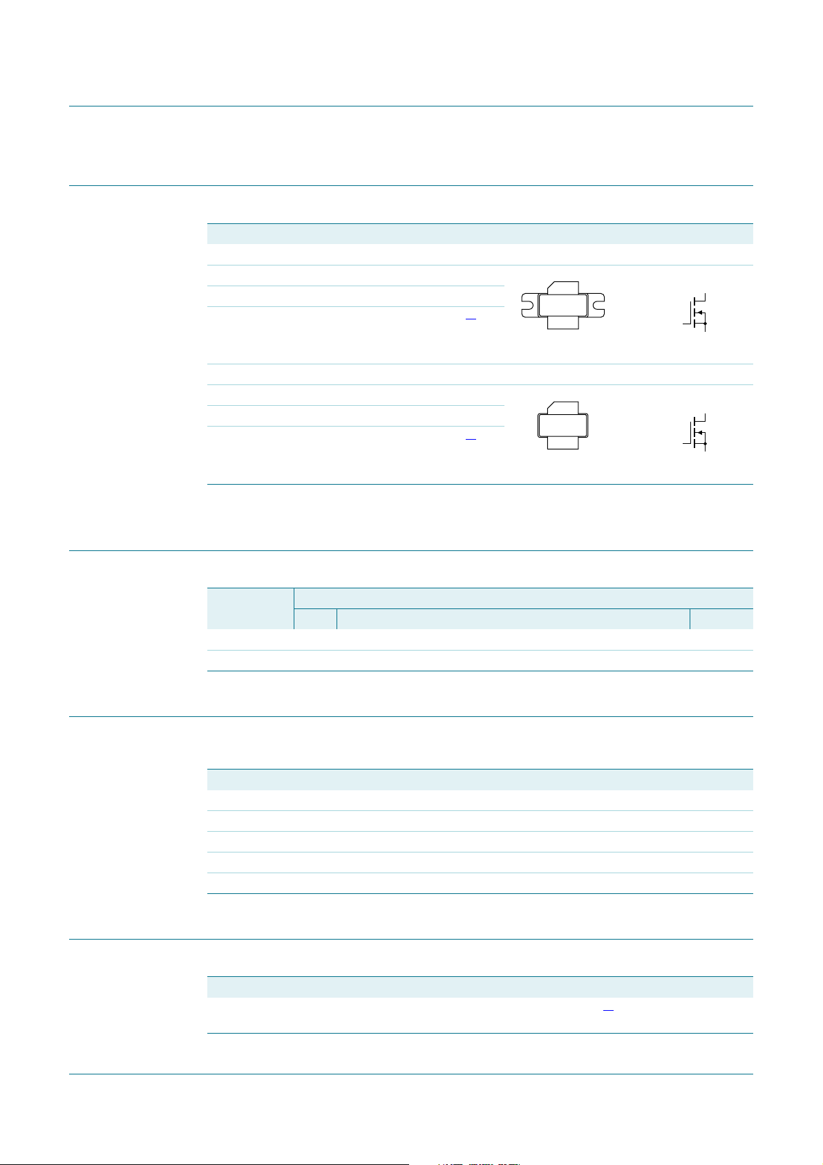
2. Pinning information
Table 2. Pinning
Pin Description Simplified outline Graphic symbol
BLF573 (SOT502A)
1drain
2gate
3source
BLF573S (SOT502B)
1drain
2gate
3source
BLF573; BLF573S
HF / VHF power LDMOS transistor
2
sym11
2
sym11
1
3
1
3
1
[1]
[1]
2
1
2
3
3
[1] Connected to flange.
3. Ordering information
Table 3. Ordering information
Type number Package
BLF573 - flanged LDMOST ceramic package; 2 mounting holes; 2 leads SOT502A
BLF573S - earless flanged LDMOST ceramic package, 2 leads SOT502B
4. Limiting values
Table 4. Limiting values
In accordance with the Absolute Maximum Rating System (IEC 60134).
Symbol Parameter Conditions Min Max Unit
V
DS
V
GS
I
D
T
stg
T
j
drain-source voltage - 110 V
gate-source voltage −0.5 +11 V
drain current - 42 A
storage temperature −65 +150 °C
junction temperature - 225 °C
Name Description Version
5. Thermal characteristics
Table 5. Thermal characteristics
Symbol Parameter Conditions Typ Unit
R
th(j-c)
thermal resistance from
T
=80°C; PL=300W
case
junction to case
[1] R
BLF573_BLF573S All information provided in this document is subject to legal disclaimers. © NXP B.V. 2010. All rights reserved.
Product data sheet Rev. 3 — 8 July 2010 2 of 16
is measured under RF conditions.
th(j-c)
[1]
0.21 K/W
Page 3

NXP Semiconductors
6. Characteristics
Table 6. DC characteristics
Tj = 25 °C unless otherwise specified.
Symbol Parameter Conditions Min Typ Max Unit
V
(BR)DSS
V
GS(th)
V
GSq
I
DSS
I
DSX
I
GSS
g
fs
R
DS(on)
C
rs
C
iss
C
oss
BLF573; BLF573S
HF / VHF power LDMOS transistor
drain-source breakdown voltage VGS=0V; ID=3.75mA 110 - - V
gate-source threshold voltage VDS=10 V; ID= 375 mA 1.25 1.7 2.25 V
gate-source quiescent voltage VDS=50 V; ID= 900 mA 1.45 1.95 2.45 V
drain leakage current VGS=0V; VDS=50V - - 4.2 μA
drain cut-off current VGS=V
=10V
V
DS
GS(th)
+3.75 V;
gate leakage current VGS=11V; VDS= 0 V - - 420 nA
forward transconductance VDS=10V; ID= 18.75 A - 20 - S
drain-source on-state resistance VGS=V
GS(th)
+ 3.75 V;
ID= 12.49 A
feedback capacitance VGS=0V; VDS=50V;
f=1MHz
input capacitance VGS=0V; VDS=50V;
f=1MHz
output capacitance VGS=0V; VDS=50V;
f=1MHz
44 56 - A
-0.09-Ω
-2.3-pF
- 300 - pF
- 103 - pF
Table 7. RF characteristics
Mode of operation: CW; f = 225 MHz; RF performance at V
=50V; IDq=900 mA; T
DS
case
= 25 °C;
unless otherwise specified; in a class-AB production test circuit.
Symbol Parameter Conditions Min Typ Max Unit
G
RL
η
p
D
power gain PL = 300 W 26 27.2 28.4 dB
input return loss PL = 300 W 10 13 - dB
in
drain efficiency PL = 300 W 67 70 - %
BLF573_BLF573S All information provided in this document is subject to legal disclaimers. © NXP B.V. 2010. All rights reserved.
Product data sheet Rev. 3 — 8 July 2010 3 of 16
Page 4
NXP Semiconductors
001aaj141
9
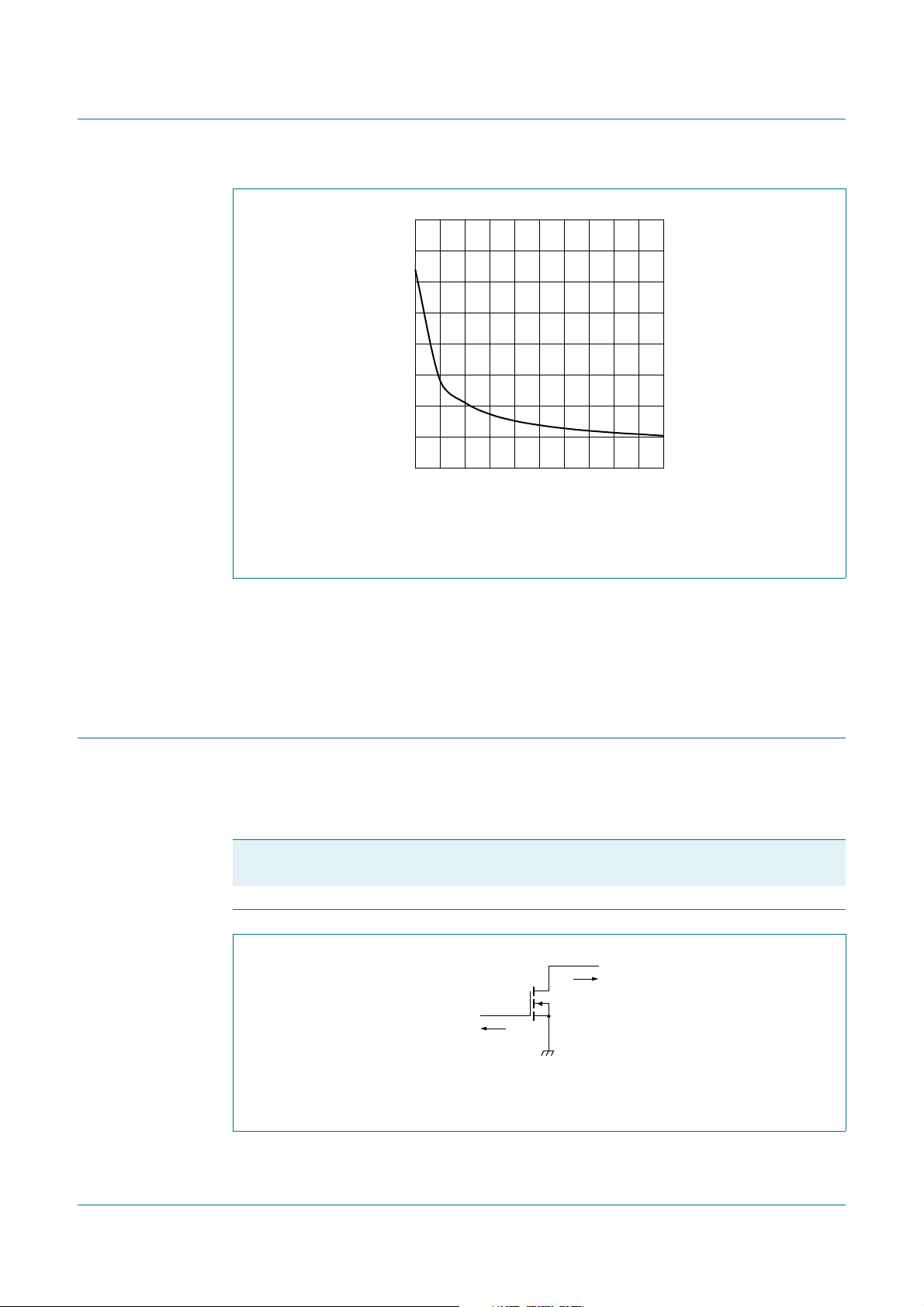
Fig 1. Output capacitance as a fun ction of drain-source voltage; capacitance value
800
C
oss
(pF)
600
400
200
0
0504020 3010
VGS = 0 V; f = 1 MHz.
without internal matching
BLF573; BLF573S
HF / VHF power LDMOS transistor
VDS (V)
6.1 Ruggedness in class-AB operation
The BLF573 and BLF573S are capable o f withsta nding a load mismatch corresponding to
VSWR = 13 : 1 through all phases under the following conditions: V
I
=900mA; PL= 300 W; f = 225 MHz.
Dq
7. Application information
7.1 Impedance information
Table 8. Typical impedance
Measured ZS and ZL test circuit impedances.
f Z
MHz Ω Ω
225 0.7 + j2.0 1.95 + j2.0
=50V;
DS
S
drain
Z
L
gate
Z
S
001aaf05
Z
L
Fig 2. Definition of transistor impedanc e
BLF573_BLF573S All information provided in this document is subject to legal disclaimers. © NXP B.V. 2010. All rights reserved.
Product data sheet Rev. 3 — 8 July 2010 4 of 16
Page 5
NXP Semiconductors
001aaj142
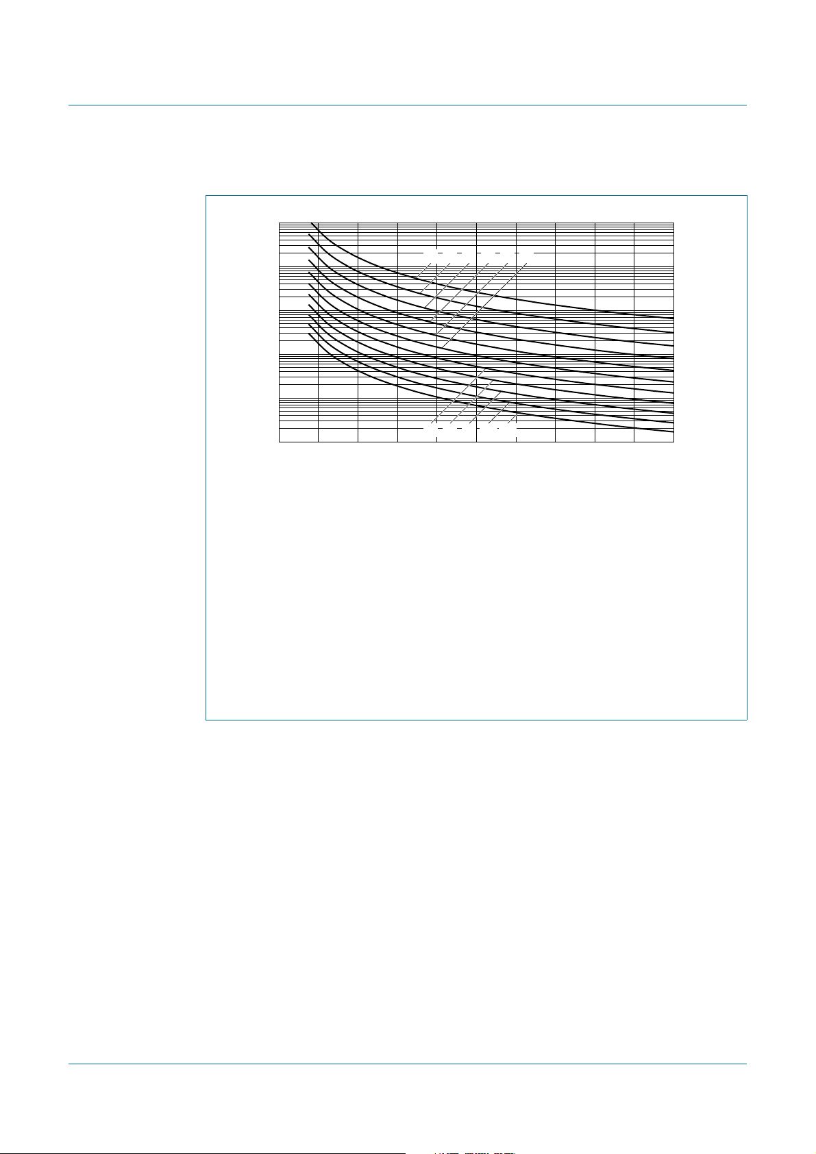
7.2 Reliability
Years
BLF573; BLF573S
HF / VHF power LDMOS transistor
5
10
4
10
3
10
2
10
10
(1) (2) (3) (4) (5) (6)
1
0 20168124
(7) (8) (9) (10)
(11)
TTF (0.1 % failure fraction).
= 100 °C
(1) T
j
= 110 °C
(2) T
j
= 120 °C
(3) T
j
= 130 °C
(4) T
j
= 140 °C
(5) T
j
= 150 °C
(6) T
j
= 160 °C
(7) T
j
= 170 °C
(8) T
j
= 180 °C
(9) T
j
= 190 °C
(10) T
j
= 200 °C
(11) T
j
Fig 3. BLF573 and BLF573S electromigration (ID, total device)
(A)
I
dc
BLF573_BLF573S All information provided in this document is subject to legal disclaimers. © NXP B.V. 2010. All rights reserved.
Product data sheet Rev. 3 — 8 July 2010 5 of 16
Page 6
NXP Semiconductors
001aaj612
001aaj613
8. Test information
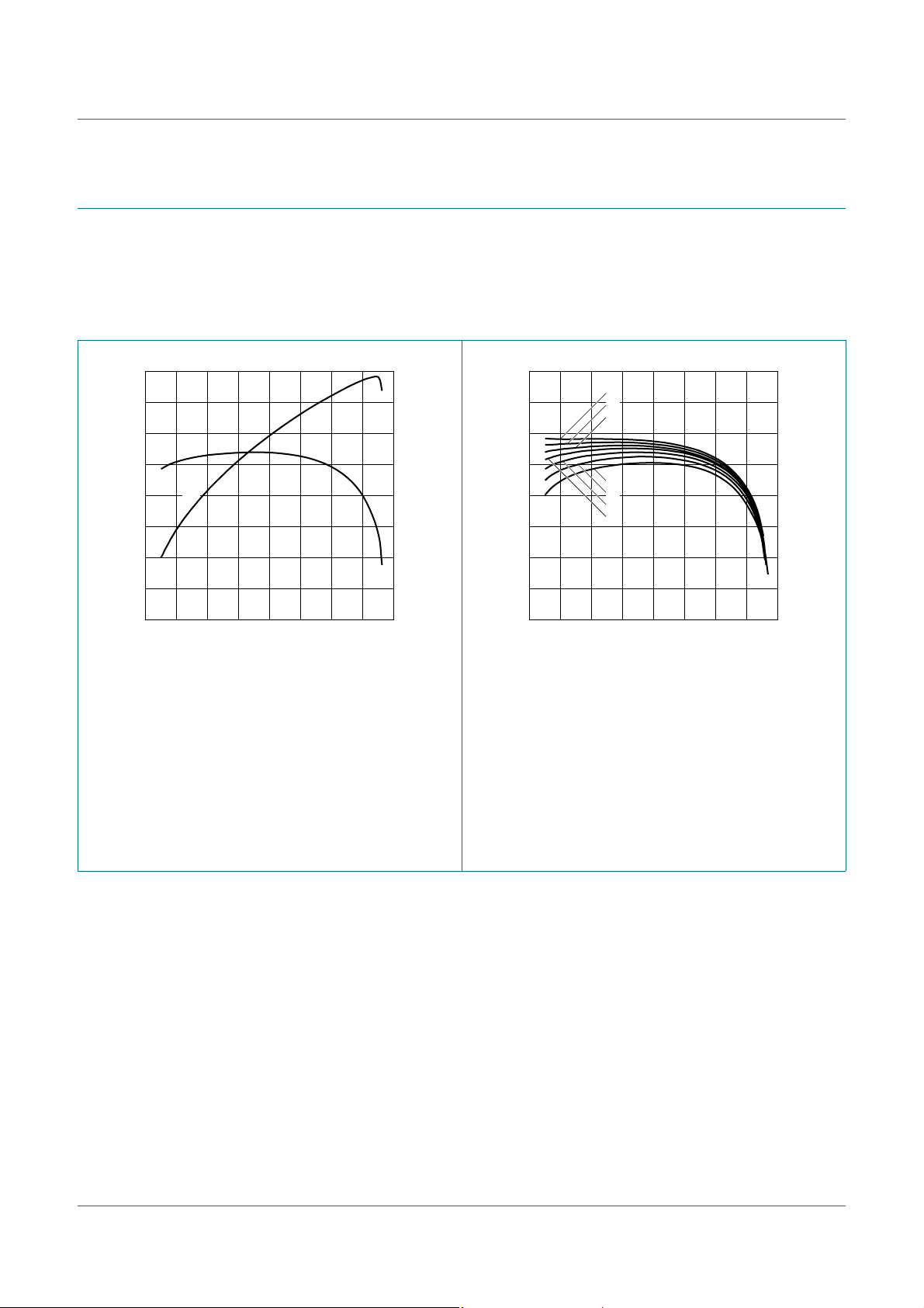
8.1 RF Performance
The following figures are measured in a class-AB production test circuit.
8.1.1 1-Tone CW
BLF573; BLF573S
HF / VHF power LDMOS transistor
30
G
p
(dB)
28
26
24
22
G
p
η
D
0 400300100 200
PL (W)
80
η
D
(%)
60
40
20
0
VDS = 50 V; IDq= 900 mA; f = 225 MHz. VDS = 50 V; f = 225 MHz.
Fig 4. Power gain and drain efficiency as functions
of load power; typical values
30
G
p
(dB)
28
26
24
22
0 400300100 200
= 500 mA
(1) I
Dq
= 700 mA
(2) I
Dq
= 900 mA
(3) I
Dq
= 1100 mA
(4) I
Dq
= 1300 mA
(5) I
Dq
= 1500 mA
(6) I
Dq
= 1700 mA
(7) I
Dq
(7)
(6)
(5)
(1)
(2)
(3)
(4)
PL (W)
Fig 5. Power gain as function of load power; typical
values
BLF573_BLF573S All information provided in this document is subject to legal disclaimers. © NXP B.V. 2010. All rights reserved.
Product data sheet Rev. 3 — 8 July 2010 6 of 16
Page 7
NXP Semiconductors
BLF573; BLF573S
HF / VHF power LDMOS transistor
60
P
L
(dBm)
58
56
54
52
50
24 343228 3026
Ideal P
(1)
L
P
L
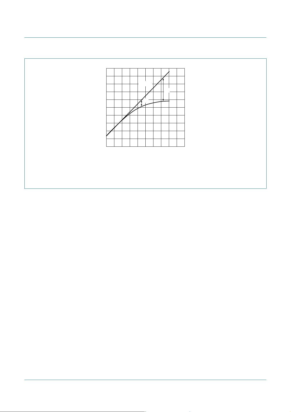
VDS = 50 V; IDq= 900 mA; f = 225 MHz.
(1) P
(2) P
= 55.2 dBm (330 W)
L(1dB)
= 55.8 dBm (380 W)
L(3dB)
Fig 6. Load power as function of input power; typical values
001aaj614
(2)
Pi (dBm)
BLF573_BLF573S All information provided in this document is subject to legal disclaimers. © NXP B.V. 2010. All rights reserved.
Product data sheet Rev. 3 — 8 July 2010 7 of 16
Page 8
NXP Semiconductors
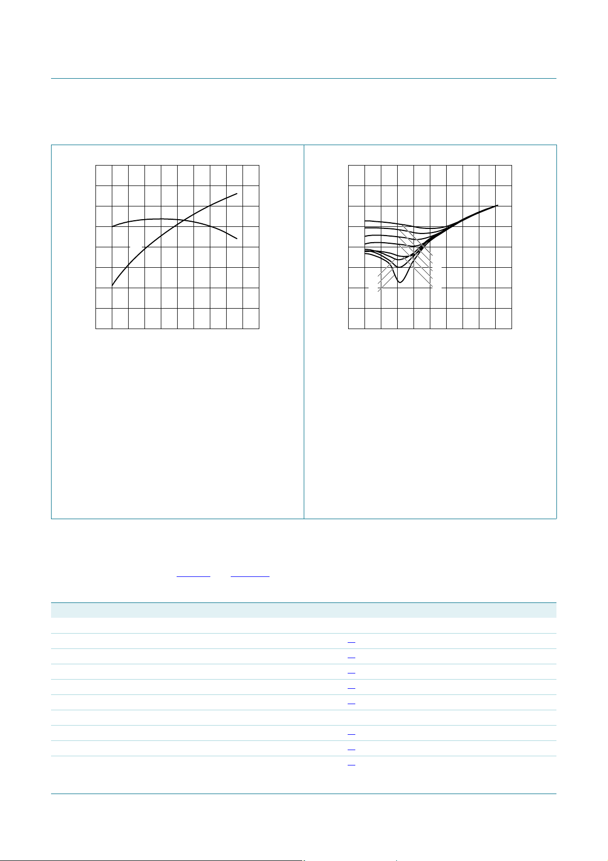
8.1.2 2-Tone CW
BLF573; BLF573S
HF / VHF power LDMOS transistor
001aaj615
P
L(PEP)
(W)
80
η
D
(%)
60
40
20
0
G
(dB)
30
p
28
26
24
22
0 500400200 300100
G
p
η
D
VDS = 50 V; IDq= 900 mA; f1 = 224.95 MHz;
f
= 225.05 MHz.
2
Fig 7. Power gain and drain efficiency as functions
of peak envelope load power; typical values
001aaj616
P
L(PEP)
(W)
IMD3
(dBc)
−20
−40
−60
−80
(1) I
(2) I
(3) I
(4) I
(5) I
(6) I
(7) I
(8) I
0
(1)
(2)
(8)
(7)
(6)
0 500400200 300100
= 50 V; f1 = 224.95 MHz; f2= 225.05 MHz.
V
DS
= 500 mA
Dq
= 700 mA
Dq
= 900 mA
Dq
= 1100 mA
Dq
= 1300 mA
Dq
= 1500 mA
Dq
= 1700 mA
Dq
= 1800 mA
Dq
(3)
(4)
(5)
Fig 8. Third order intermodulation distortion as a
function of peak envelope load power; typical
values
8.2 Test circuit
Table 9. List of components
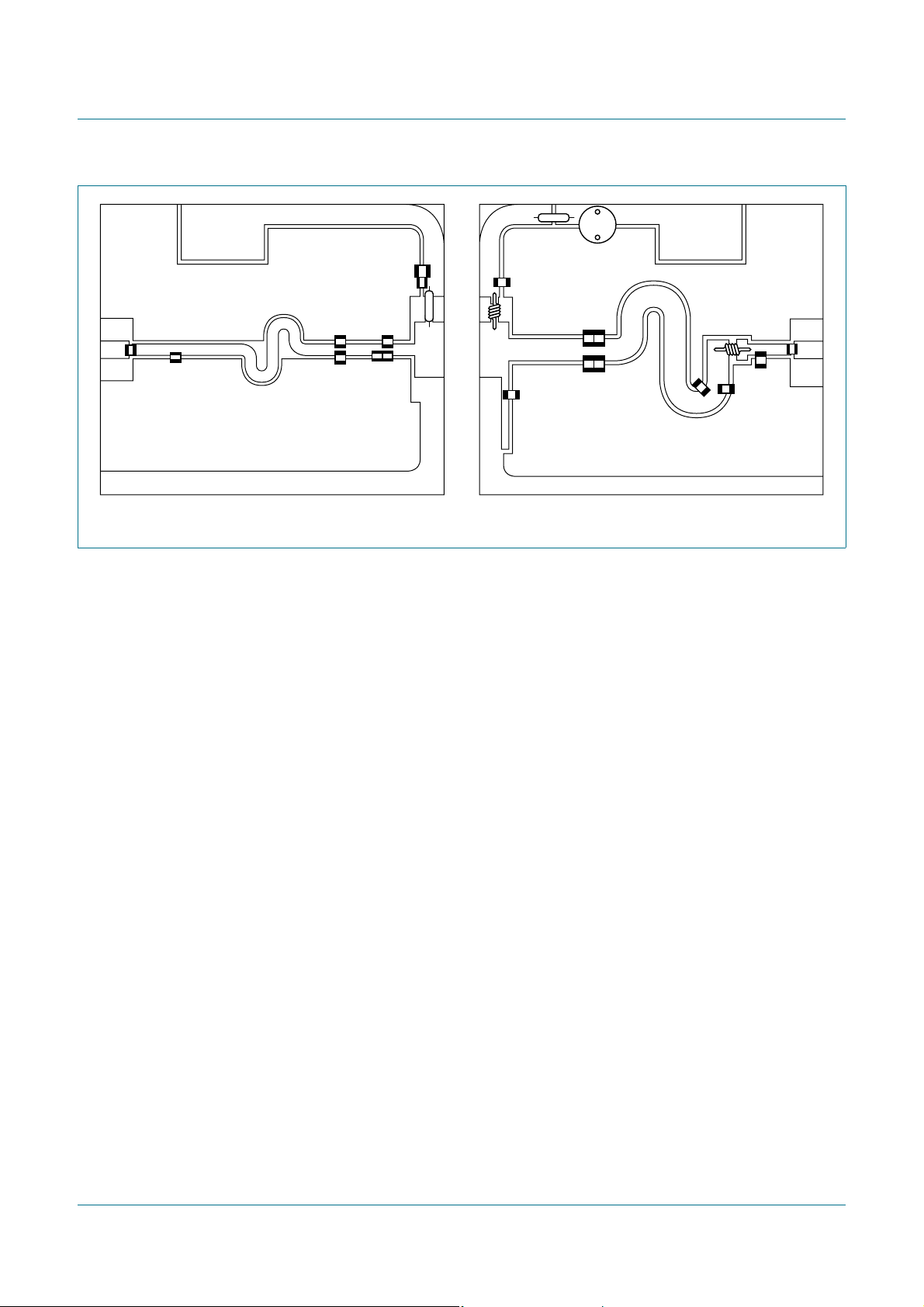
For production test circuit, see Figure 9
Printed-Circuit Board (PCB): Rogers 5880;
thickness copper plating = 35
Component Description Value Remarks
B1 ferrite SMD bead 100 Ω; 100 MHz Ferroxcube BDS3/3/8.9-4S2 or equivalent
C1, C18 multilayer ceramic chip capacitor 100 pF
C2 multilayer ceramic chip capacitor 39 pF
C3, C4 multilayer ceramic chip capacitor 180 pF
C5, C6, C7 multilayer ceramic chip capacitor 220 pF
C8, C20 multilayer ceramic chip capacitor 1 nF
C9 multilayer ceramic chip capacitor 4.7 μF TDK C4532X7R1E475MT020U or equivalent
C10 multilayer ceramic chip capacitor 30 pF
C11, C12, C13 multilayer ceramic chip capacitor 51 pF
C14 multilayer ceramic chip capacitor 43 pF
BLF573_BLF573S All information provided in this document is subject to legal disclaimers. © NXP B.V. 2010. All rights reserved.
Product data sheet Rev. 3 — 8 July 2010 8 of 16
and Figure 10.
ε
= 2.2 F/m; height = 0.79 mm; Cu (top/bottom metallization);
μ
m.
r
[1]
[1]
[1]
[1]
[1]
[1]
[1]
[1]
Page 9
NXP Semiconductors
8
BLF573; BLF573S
HF / VHF power LDMOS transistor
Table 9. List of components
…continued
For production test circuit, see Figure 9 and Figure 10.
Printed-Circuit Board (PCB): Rogers 5880;
ε
= 2.2 F/m; height = 0.79 mm; Cu (top/bottom metallization);
r
thickness copper plating = 35μm.
Component Description Value Remarks
C15 multilayer ceramic chip capacitor 33 pF
C16 multilayer ceramic chip capacitor 36 pF
C17 multilayer ceramic chip capacitor 16 pF
[1]
[1]
[1]
C19 electrolytic capacitor 220 μF; 63 V
L1 2 turns enamel led copper wire D = 3 mm;
d=1mm;
length = 2 mm;
leads = 2 × 6mm
L2 4 turns enamel led copper wire D = 2 mm;
d=1mm;
length = 13 mm;
leads = 2 × 5mm
L3 stripline - (L × W) 96 mm × 3mm
L4, L5 stripline - (L × W) 15 mm × 8mm
L6 stripline - (L × W) 105 mm × 6mm
L7 stripline - (L × W) 3 mm × 6mm
L8 stripline - (L × W) 12 mm × 6mm
R1 metal film resistor 100 Ω; 0.6 W
[1] American Technical Ceramics type 100B or capacitor of same quality.
V
DD
V
GG
C9
C8
R1
input
50 Ω
C1
L3
C2
C3
C7
L5L4
C4
C5 C6
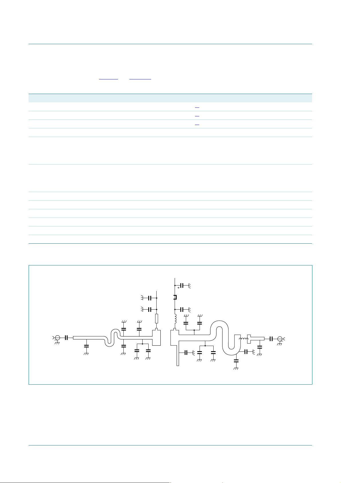
Fig 9. Class-AB common-source prod uc tio n tes t ci rc u it
C19
B1
C20
L1
C13 C14
L6
C10
C11 C12
C15
L2
C16
C17
C18
output
50 Ω
001aaj14
L7
L8
BLF573_BLF573S All information provided in this document is subject to legal disclaimers. © NXP B.V. 2010. All rights reserved.
Product data sheet Rev. 3 — 8 July 2010 9 of 16
Page 10
NXP Semiconductors
9
C9
C8
C3
C1
C2
C4
Fig 10. Component layout for class-AB production test circuit
C7
R1
C6C5
BLF573; BLF573S
HF / VHF power LDMOS transistor
B1
C19
C20
C13
L1
C14
C11 C12
C10
C15
L2
C18
C17
C16
001aaj14
BLF573_BLF573S All information provided in this document is subject to legal disclaimers. © NXP B.V. 2010. All rights reserved.
Product data sheet Rev. 3 — 8 July 2010 10 of 16
Page 11
NXP Semiconductors
A
BLF573; BLF573S
HF / VHF power LDMOS transistor
9. Package outline
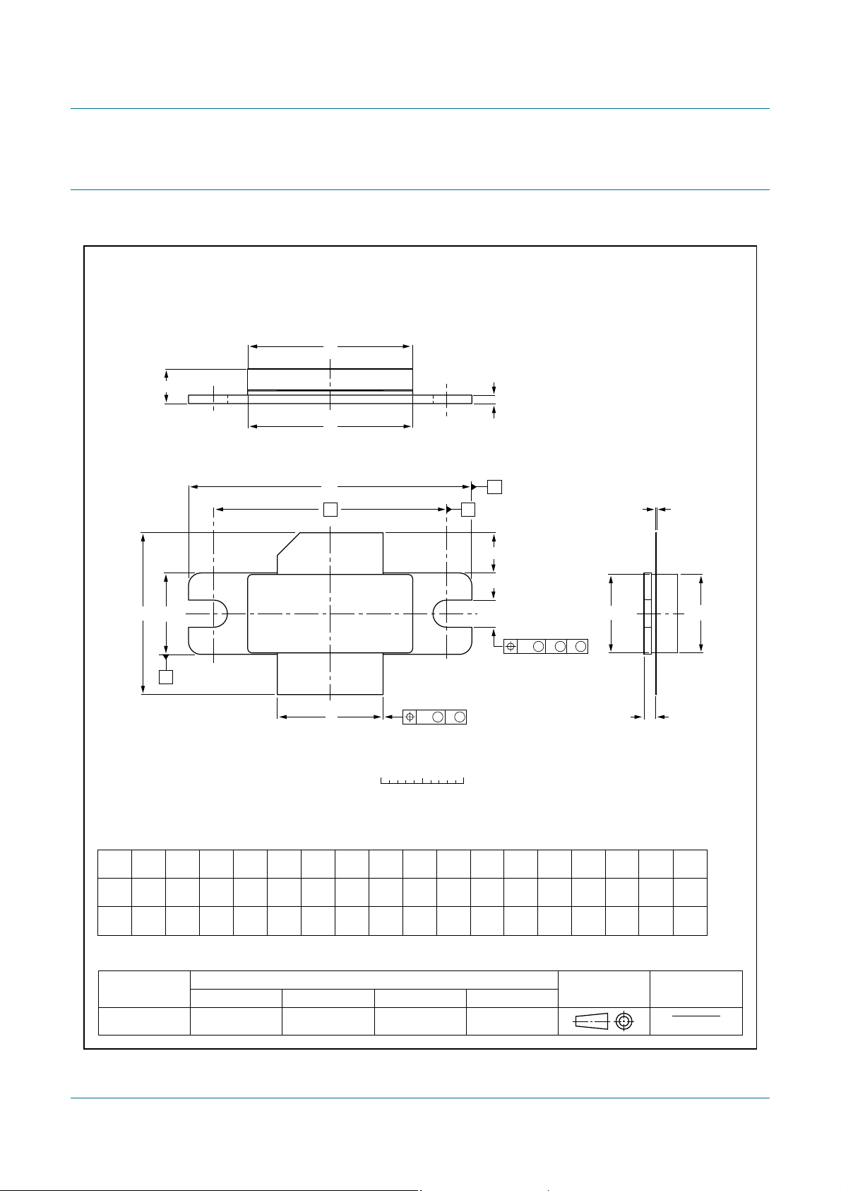
Flanged LDMOST ceramic package; 2 mounting holes; 2 leads SOT502
D
A
3
D
1
U
1
q
1
H
U
2
A
2
b
w
M M
C
2
0 5 10 mm
scale
F
B
C
L
p
w
M M M
AB
1
c
E
1
Q
E
DIMENSIONS (millimetre dimensions are derived from the original inch dimensions)
UNIT
mm
inches
A
4.72
3.43
0.186
0.135
OUTLINE
VERSION
SOT502A
12.83
12.57
0.505
0.495
c
0.15
0.08
0.006
0.003
IEC JEDEC JEITA
Db
20.02
19.61
0.788
0.772
D
19.96
19.66
0.786
0.774
1
EE
9.50
9.53
9.30
9.25
0.374
0.375
0.366
0.364
REFERENCES
1
0.045
0.035
F
1.14
0.89
H
19.94
18.92
0.785
0.745
L
5.33
4.32
0.210
0.170
p
3.38
3.12
0.133
0.123
Q
1.70
1.45
0.067
0.057
qw
U
1
34.16
33.91
1.345
1.335
EUROPEAN
PROJECTION
U
2
9.91
9.65
0.390
0.380
w
1
0.25 0.5127.94
0.01 0.021.100
ISSUE DATE
2
99-12-28
03-01-10
Fig 11. Package outline SOT502A
BLF573_BLF573S All information provided in this document is subject to legal disclaimers. © NXP B.V. 2010. All rights reserved.
Product data sheet Rev. 3 — 8 July 2010 11 of 16
Page 12
NXP Semiconductors
B
BLF573; BLF573S
HF / VHF power LDMOS transistor
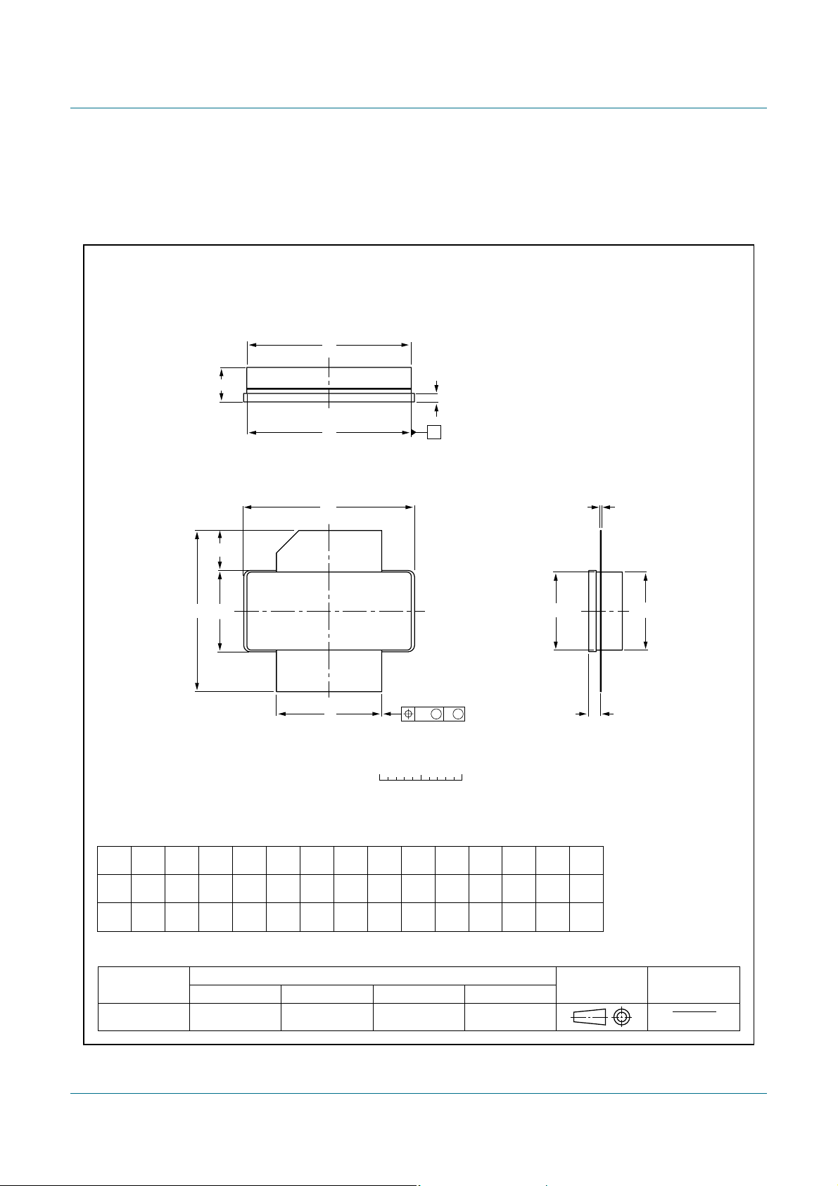
Earless flanged LDMOST ceramic package; 2 leads SOT502
D
A
3
D
1
U
1
L
H
U
2
1
2
b
0 5 10 mm
w
scale
D
2
F
M M
D
c
E
1
Q
E
DIMENSIONS (millimetre dimensions are derived from the original inch dimensions)
UNIT
mm
inches
A
4.72
3.43
0.186
0.135
OUTLINE
VERSION
SOT502B
12.83
12.57
0.505
0.495
c
Db
20.02
19.61
0.788
0.772
19.96
19.66
0.786
0.774
0.15
0.08
0.006
0.003
IEC JEDEC JEITA
D
1
EE
9.53
9.50
9.25
9.30
0.374
0.375
0.366
0.364
REFERENCES
1
0.045
0.035
F
1.14
0.89
H
19.94
18.92
0.785
0.745
L
5.33
4.32
0.210
0.170
Q
1.70
1.45
0.067
0.057
U
20.70
20.45
0.815
0.805
U
w
2
1
9.91
9.65
0.390
0.380
2
0.25
0.010
EUROPEAN
PROJECTION
ISSUE DATE
03-01-10
07-05-09
Fig 12. Package outline SOT502B
BLF573_BLF573S All information provided in this document is subject to legal disclaimers. © NXP B.V. 2010. All rights reserved.
Product data sheet Rev. 3 — 8 July 2010 12 of 16
Page 13

NXP Semiconductors
10. Abbreviations
Table 10. Abbreviations
Acronym Description
CW Continuous Wave
EDGE Enhanced Data rates for GSM Evolution
GSM Global System for Mobile communications
HF High Frequency
LDMOS Laterally Diffused Metal-Oxide Semiconductor
LDMOST Laterally Diffused Metal-Oxide Semiconductor Transistor
RF Radio Frequency
SMD Surface Mount Device
TTF Time To Failure
VHF Very High Frequency
VSWR Voltage Standing-Wave Ratio
BLF573; BLF573S
HF / VHF power LDMOS transistor
11. Revision history
Table 11. Revision history
Document ID Release date Data sheet status Change notice Supersedes
BLF573_BLF573S v.3 20100708 Product data sheet - BLF573S v.2
Modifications:
BLF573S v.2 20090217 Product data sheet - BLF573S v.1
BLF573S v.1 20081208 Preliminary data sheet - -
• The document now describes both the eared and earless version of this product:
BLF573 and BLF573S respectively.
BLF573_BLF573S All information provided in this document is subject to legal disclaimers. © NXP B.V. 2010. All rights reserved.
Product data sheet Rev. 3 — 8 July 2010 13 of 16
Page 14

NXP Semiconductors
BLF573; BLF573S
HF / VHF power LDMOS transistor
12. Legal information
12.1 Data sheet status
Document status
Objective [short] data sheet Development This document contains data from the objective specification for product development .
Preliminary [short] data sheet Qualification This document contains data from the preliminary specification.
Product [short] data sheet Producti on This document contains the product specification.
[1] Please consult the most recently issued document before initiating or completing a design.
[2] The term ‘short data sheet’ is explained in section “Definitions”.
[3] The product status of device(s) described in this docu ment may have changed si nce this docum ent was pub lished and may dif fer in case of multiple devices. The latest product statu s
information is available on the Internet at URL http://www.nxp.com.
[1][2]
Product status
[3]
Definition
12.2 Definitions
Draft — The document is a draft version only. The content is still under
internal review and subject to formal approval, which may result in
modifications or additions. NXP Semiconductors does not give any
representations or warranties as to the accuracy or completeness of
information included herein and shall have no liability for the consequences of
use of such information.
Short data sheet — A short data sheet is an extract from a full data sheet
with the same product type number(s) and title. A short data sheet is intended
for quick reference only and should not be relied u pon to co nt ain det ailed and
full information. For detailed and full information see the relevant full data
sheet, which is available on request via the local NXP Semiconductors sales
office. In case of any inconsistency or conflict with the short data sheet, the
full data sheet shall prevail.
Product specification — The information and data provided in a Product
data sheet shall define the specification of the product as agreed between
NXP Semiconductors and its customer, unless NXP Semiconductors and
customer have explicitly agreed otherwise in writing. In no event however,
shall an agreement be valid in which the NXP Semiconductors product is
deemed to offer functions and qualities beyond those described in the
Product data sheet.
12.3 Disclaimers
Limited warranty and liability — Information in this document is believed to
be accurate and reliable. However, NXP Semiconductors does not give any
representations or warranties, expressed or implied, as to the accuracy or
completeness of such information and shall have no liability for the
consequences of use of such information.
In no event shall NXP Semiconductors be lia ble for any indirect, incidental,
punitive, special or consequential damages (including - without limitation - lost
profits, lost savings, business interruption, costs related to the removal or
replacement of any products or rework charges) whether or not such
damages are based on tort (including negligence), warranty, breach of
contract or any other legal theory.
Notwithstanding any damages that customer might incur for any reason
whatsoever, NXP Semi conductors’ aggregat e and cumulative liabil ity towards
customer for the products described herein shall be limited in accordance
with the Terms and conditions of commercial sale of NXP Semiconductors.
Right to make changes — NXP Semiconductors reserves the right to make
changes to information published in this document, including without
limitation specifications and product descriptions, at any time and without
notice. This document supersedes and replaces all information supplied prior
to the publication hereof.
Suitability for use — NXP Semiconductors products are not designed,
authorized or warranted to be suitable for use in life support, life-critical or
safety-critical systems or equipment, nor in applications where failure or
malfunction of an NXP Semiconductors product can reasonabl y be expected
to result in personal injury, death or severe property or environmental
damage. NXP Semiconductors accepts no liability for inclusion and/or use of
NXP Semiconductors products in such equipment or applications and
therefore such inclusion and/or use is at the customer’s own risk.
Applications — Applications that are described herein for any of these
products are for illustrative purposes only. NXP Semiconductors makes no
representation or warranty that such applications will be suitable for the
specified use without further testing or modification.
Customers are responsible for the design and operation of their applications
and products using NXP Semiconductors products, and NXP Semiconductors
accepts no liability for any assistance with applications or customer product
design. It is customer’s sole responsibility to determine whether the NXP
Semiconductors product is suitable and fit for the customer’s applications and
products planned, as well as for the planned application and use of
customer’s third party customer(s). Customers should provide appropriate
design and operating safeguards to minimize the risks associated with their
applications and products.
NXP Semiconductors does not accept any liability related to any default ,
damage, costs or problem which is based on any weakness or default in the
customer’s applications or products, or the application or use by customer’s
third party customer(s). Customer is responsible for doing all necessary
testing for the customer’s applications and products using NXP
Semiconductors products in order to avoid a default of the applications and
the products or of the application or use by customer’s third part y
customer(s). NXP does not accept any liability in this respect.
Limiting values — Stress above one or more limiting values (as defined in
the Absolute Maximum Ratings System of IEC 60134) will cause permanent
damage to the device. Limiting values are stress ratings only and (proper)
operation of the device at these or any other conditions above those given in
the Recommended operating conditions section (if present) or the
Characteristics sections of this document is not warranted. Constant or
repeated exposure to limiting values will permanently and irreversibly affect
the quality and reliability of the device.
Terms and conditions of commercial sale — NXP Semiconductors
products are sold subject to the general terms and conditions of commercial
sale, as published at http://www.nxp.com/profile/terms
agreed in a valid written individual agreement. In case an individual
agreement is concluded only the terms and conditions of the respective
agreement shall apply. NXP Semiconductors hereby expressly objects to
applying the customer’s general terms and conditions with regard to the
purchase of NXP Semiconductors products by customer.
No offer to sell or license — Nothing in this document may be interpreted or
construed as an offer to sell product s that is ope n for accept ance or the gr ant,
conveyance or implication of any license under any copyrights, patents or
other industrial or intellectual property rights.
Export control — This document as well as the item(s) described herein
may be subject to export control regulations. Export might require a prior
authorization from national authorities.
, unless otherwise
BLF573_BLF573S All information provided in this document is subject to legal disclaimers. © NXP B.V. 2010. All rights reserved.
Product data sheet Rev. 3 — 8 July 2010 14 of 16
Page 15

NXP Semiconductors
BLF573; BLF573S
HF / VHF power LDMOS transistor
Non-automotive qualified products — Unless this data sheet expressly
states that this specific NXP Semiconductors product is automotive qualified,
the product is not suitable for automotive use. It i s neither qua lif ied nor test ed
in accordance with automotive testing or application requirements. NXP
Semiconductors accepts no liability for inclusion and/or use of
non-automotive qualified products in automotive equ ipment or applications.
In the event that customer uses the product for design-in and use in
automotive applications to automotive specifications and standards, customer
(a) shall use the product without NXP Semiconductors’ warranty of the
product for such automotive applications, use and specifications, and (b)
whenever customer uses the product for automotive applications beyond
NXP Semiconductors’ specifications such use shall be solely at customer’s
own risk, and (c) customer fully indemnifies NXP Semiconductors for any
liability, da mages or failed produ ct cl aims resulting from custome r design and
use of the product for automotive applications beyond NXP Semiconductors’
standard warranty and NXP Semiconductors’ product specifications.
12.4 Trademarks
Notice: All referenced brands, prod uct names, service names and trad emarks
are the property of their respective owners.
13. Contact information
For more information, please visit: http://www.nxp.com
For sales office addresses, please send an email to: [email protected]
BLF573_BLF573S All information provided in this document is subject to legal disclaimers. © NXP B.V. 2010. All rights reserved.
Product data sheet Rev. 3 — 8 July 2010 15 of 16
Page 16

NXP Semiconductors
14. Contents
1 Product profile . . . . . . . . . . . . . . . . . . . . . . . . . . 1
1.1 General description . . . . . . . . . . . . . . . . . . . . . 1
1.2 Features and benefits. . . . . . . . . . . . . . . . . . . . 1
1.3 Applications . . . . . . . . . . . . . . . . . . . . . . . . . . . 1
2 Pinning information. . . . . . . . . . . . . . . . . . . . . . 2
3 Ordering information. . . . . . . . . . . . . . . . . . . . . 2
4 Limiting values. . . . . . . . . . . . . . . . . . . . . . . . . . 2
5 Thermal characteristics . . . . . . . . . . . . . . . . . . 2
6 Characteristics. . . . . . . . . . . . . . . . . . . . . . . . . . 3
6.1 Ruggedness in class-AB operation . . . . . . . . . 4
7 Application information. . . . . . . . . . . . . . . . . . . 4
7.1 Impedance information. . . . . . . . . . . . . . . . . . . 4
7.2 Reliability . . . . . . . . . . . . . . . . . . . . . . . . . . . . . 5
8 Test information. . . . . . . . . . . . . . . . . . . . . . . . . 6
8.1 RF Performance. . . . . . . . . . . . . . . . . . . . . . . . 6
8.1.1 1-Tone CW . . . . . . . . . . . . . . . . . . . . . . . . . . . . 6
8.1.2 2-Tone CW . . . . . . . . . . . . . . . . . . . . . . . . . . . . 8
8.2 Test circuit. . . . . . . . . . . . . . . . . . . . . . . . . . . . . 8
9 Package outline . . . . . . . . . . . . . . . . . . . . . . . . 11
10 Abbreviations. . . . . . . . . . . . . . . . . . . . . . . . . . 13
11 Revision history. . . . . . . . . . . . . . . . . . . . . . . . 13
12 Legal information. . . . . . . . . . . . . . . . . . . . . . . 14
12.1 Data sheet status . . . . . . . . . . . . . . . . . . . . . . 14
12.2 Definitions. . . . . . . . . . . . . . . . . . . . . . . . . . . . 14
12.3 Disclaimers. . . . . . . . . . . . . . . . . . . . . . . . . . . 14
12.4 Trademarks. . . . . . . . . . . . . . . . . . . . . . . . . . . 15
13 Contact information. . . . . . . . . . . . . . . . . . . . . 15
14 Contents . . . . . . . . . . . . . . . . . . . . . . . . . . . . . . 16
BLF573; BLF573S
HF / VHF power LDMOS transistor
Please be aware that important notices concerning this document and the product(s)
described herein, have been included in section ‘Legal information’.
© NXP B.V. 2010. All rights reserved.
For more information, please visit: http://www.nxp.com
For sales office addresses, please send an email to: [email protected]
Document identifier: BLF573_BLF573S
Date of release: 8 July 2010
 Loading...