

Page 1
DISCRETE SEMICONDUCTORS
DATA SH EET
M3D175
BLF404
UHF power MOS transistor
Product specification
Supersedes data of 1998 Jan 29
2003 Sep 26
Page 2
Philips Semiconductors Product specification
UHF power MOS transistor BLF404
FEATURES
• High power gain
• Easy power control
• Gold metallization
• Good thermal stability
• Withstands full load mismatch
• Designed for broadband operation.
APPLICATIONS
• Communication transmittersin the VHF/UHF range with
a nominal supply voltage of 12.5 V.
DESCRIPTION
Silicon N-channel enhancement mode vertical D-MOS
powertransistor inan 8-leadSOT409ASMD packagewith
a ceramic cap.
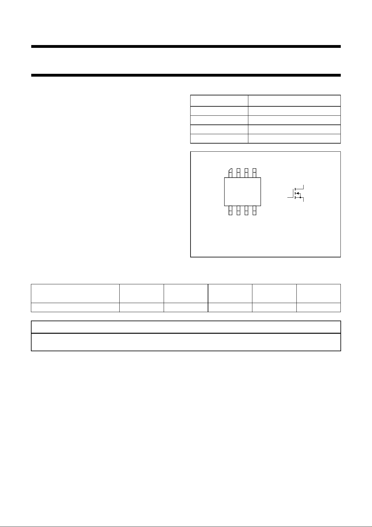
PINNING - SOT409A
PIN DESCRIPTION
1, 8 source
2, 3 gate
4, 5 source
6, 7 drain
halfpage
85
14
Top view
Fig.1 Simplified outline and symbol.
MBK150
d
g
MBB072
s
QUICK REFERENCE DATA
RF performance at Tmb≤ 60 °C in a common source test circuit.
MODE OF OPERATION
f
(MHz)
V
(V)
DS
P
(W)
L
G
(dB)
p
η
D
(%)
CW class-AB 500 12.5 4 ≥10 ≥50
CAUTION
This product is supplied in anti-static packing to prevent damage caused by electrostatic discharge during transport
and handling. For further information, refer to Philips specs.: SNW-EQ-608, SNW-FQ-302A, and SNW-FQ-302B.
2003 Sep 26 2
Page 3
Philips Semiconductors Product specification
UHF power MOS transistor BLF404
LIMITING VALUES
In accordance with the Absolute Maximum Rating System (IEC 60134).
SYMBOL PARAMETER CONDITIONS MIN. MAX. UNIT
V
DS
V
GS
I
D
P
tot
T
stg
T
j
THERMAL CHARACTERISTICS
SYMBOL PARAMETER CONDITIONS VALUE UNIT
R
th j-mb
drain-source voltage − 40 V
gate-source voltage −±20 V
drain current (DC) − 1.5 A
total power dissipation Tmb≤ 85 °C − 8.3 W
storage temperature −65 +150 °C
junction temperature − 200 °C
thermal resistance from junction to mounting base Tmb≤ 85 °C, P
= 8.3 W 12.1 K/W
tot
10
handbook, halfpage
I
D
(A)
1
−1
10
11010
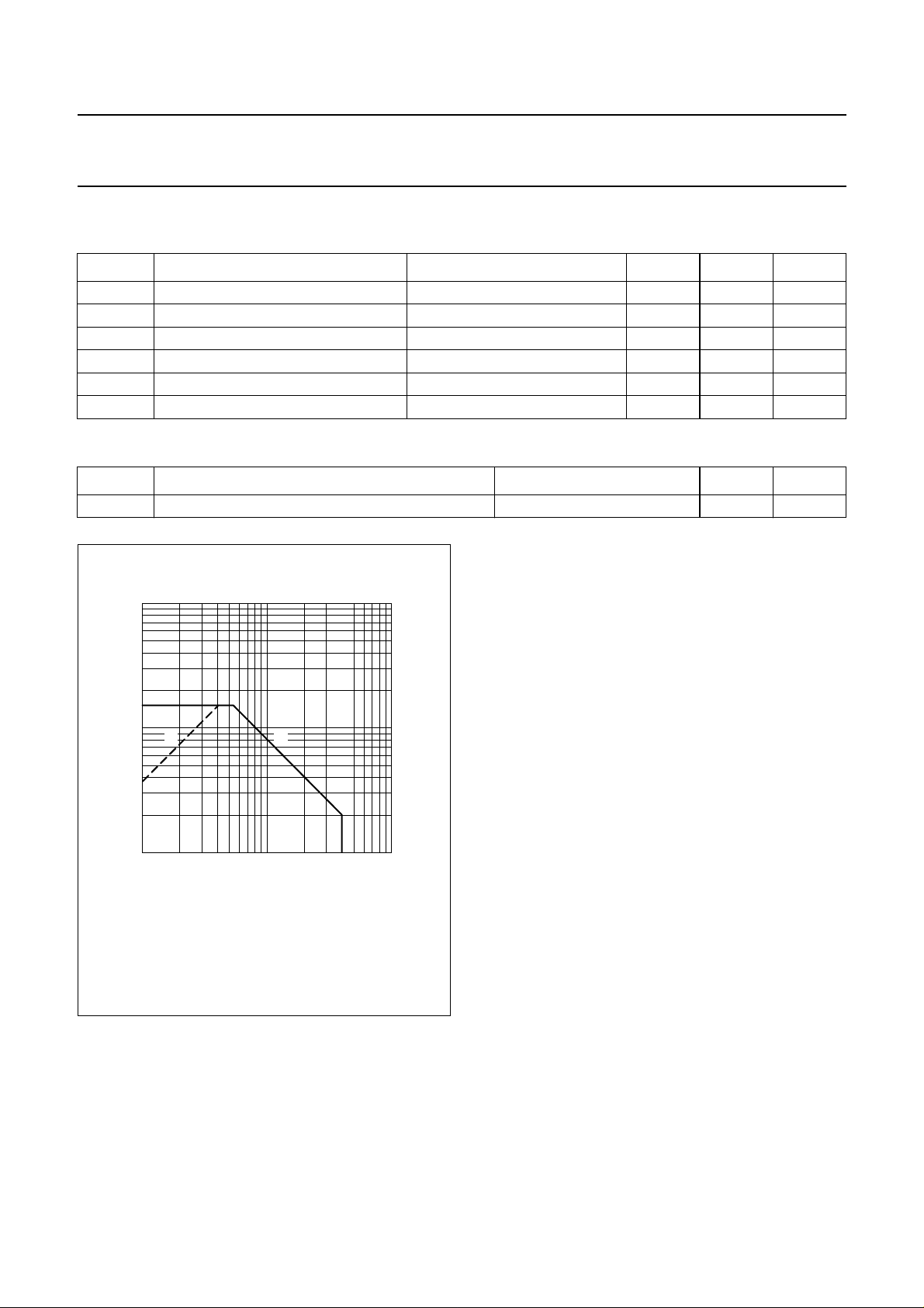
(1) Current in this area may be limited by R
(2) Tmb=85°C.
Fig.2 DC SOAR.
(2)(1)
V
(V)
DS
.
DSon
MGM522
2
2003 Sep 26 3
Page 4
Philips Semiconductors Product specification
UHF power MOS transistor BLF404
CHARACTERISTICS
Tj=25°C unless otherwise specified.
SYMBOL PARAMETER CONDITIONS MIN. TYP. MAX. UNIT
V
(BR)DSS
V
GSth
I
DSS
I
GSS
I
DSX
R
DSon
g
fs
C
is
C
os
C
rs
drain-source breakdown voltage VGS= 0; ID= 5 mA 40 −−V
gate-source threshold voltage ID= 50 mA; VDS=10V 2 − 4.5 V
drain-source leakage current VGS= 0; VDS= 12.5 V −−0.5 mA
gate-source leakage current VGS= ±20 V; VDS=0 −−1µA
on-state drain current VGS= 15 V; VDS=10V − 2.3 − A
drain-source on-state resistance ID= 0.7 A; VGS=15V − 1.8 2.7 Ω
forward transconductance ID= 0.7 A; VDS= 10 V 200 270 − mS
input capacitance VGS= 0; VDS= 12.5 V; f = 1 MHz − 14 − pF
output capacitance VGS= 0; VDS= 12.5 V; f = 1 MHz − 17 − pF
feedback capacitance VGS= 0; VDS= 12.5 V; f = 1 MHz − 3 − pF
VGS group indicator
GROUP
LIMITS
(V)
GROUP
LIMITS
(V)
MIN. MAX. MIN. MAX.
A 2.0 2.1 O 3.3 3.4
B 2.1 2.2 P 3.4 3.5
C 2.2 2.3 Q 3.5 3.6
D 2.3 2.4 R 3.6 3.7
E 2.4 2.5 S 3.7 3.8
F 2.5 2.6 T 3.8 3.9
G 2.6 2.7 U 3.9 4.0
H 2.7 2.8 V 4.0 4.1
J 2.8 2.9 W 4.1 4.2
K 2.9 3.0 X 4.2 4.3
L 3.0 3.1 Y 4.3 4.4
M 3.1 3.2 Z 4.4 4.5
N 3.2 3.3
2003 Sep 26 4
Page 5
Philips Semiconductors Product specification
UHF power MOS transistor BLF404
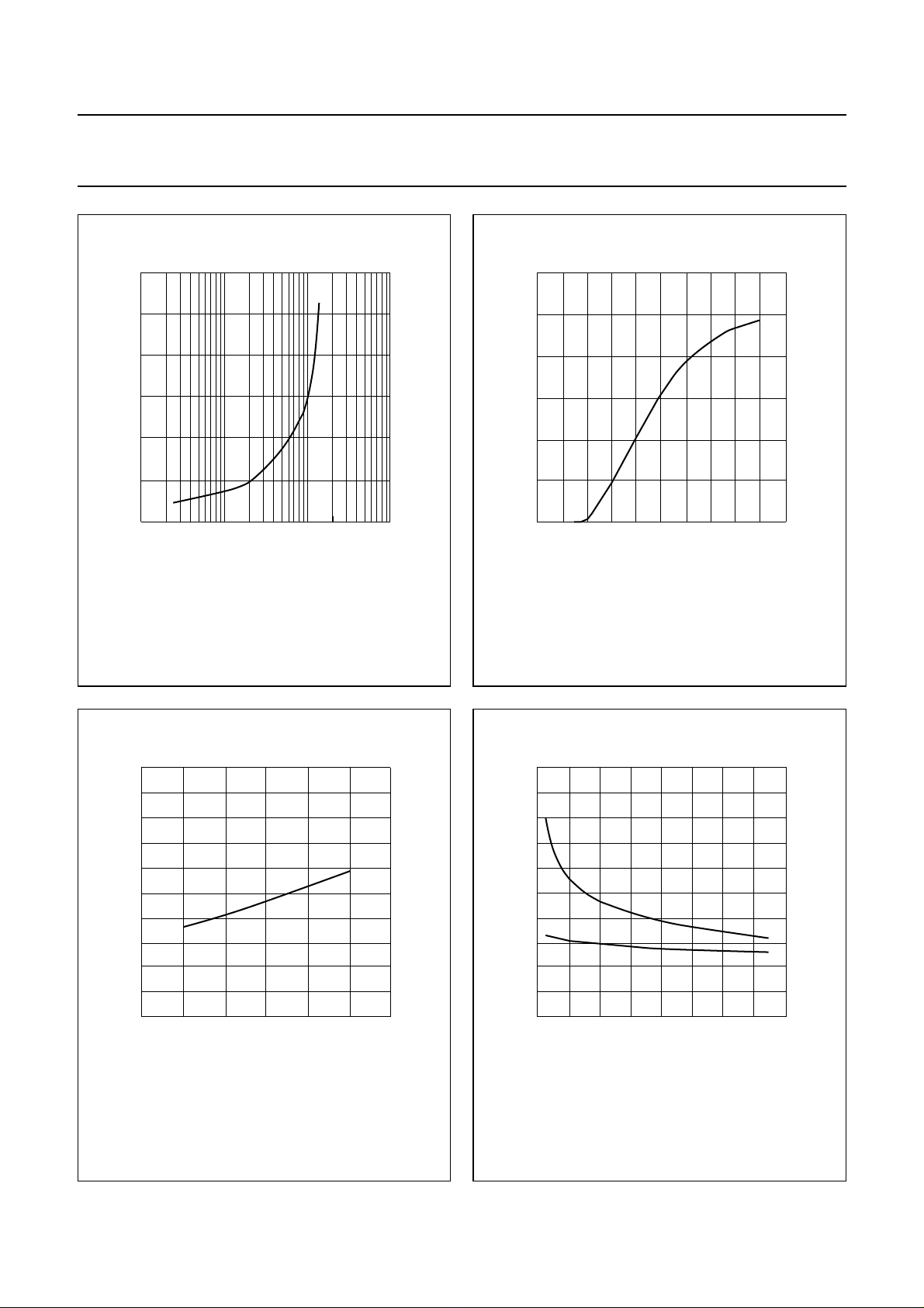
25
handbook, halfpage
T.C.
(mV/K)
15
5
−5
10 10
VDS=10V.
2
3
10
ID(mA)
Fig.3 Temperature coefficient of gate-source
voltageas afunctionof drain current;typical
values.
MRA254
handbook, halfpage
4
10
3
I
D
(A)
2
1
0
0
VDS= 10 V; Tj=25°C.
4 8 12 16 20
MRA249
VGS (V)
Fig.4 Drain current as a function of gate-source
voltage; typical values.
handbook, halfpage
5
R
DSon
(Ω)
4
3
2
1
0
0 50 100
ID= 0.7 A; VGS=15V.
Tj (
Fig.5 Drain-source on-state resistance as a
function of junction temperature; typical
values.
MRA253
o
C)
150
V
DS
MRA246
(V)
50
handbook, halfpage
C
(pF)
40
30
20
10
0
0
VGS= 0; f = 1 MHz; Tj=25°C.
C
os
C
is
4 8 12 16
Fig.6 Input and output capacitance as functions
of drain-source voltage; typical values.
2003 Sep 26 5
Page 6
Philips Semiconductors Product specification
UHF power MOS transistor BLF404
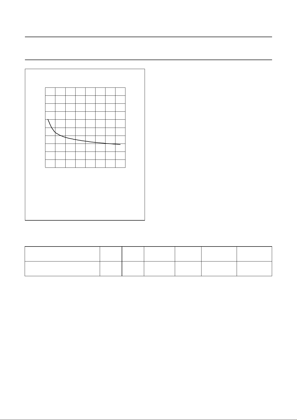
10
handbook, halfpage
C
rs
(pF)
8
6
4
2
0
0481216
VGS= 0; f = 1 MHz; Tj=25°C.
MRA256
VDS (V)
Fig.7 Feedback capacitance as a function of
drain-source voltage; typical values.
APPLICATION INFORMATION
RF performance at Tmb≤ 60 °C in a common source test circuit with the devicesoldered on a printed-circuit board with
through metallized holes.
MODE OF OPERATION
f
(MHz)
V
(V)
DS
I
DQ
(A)
P
(W)
L
G
p
(dB)
η
(%)
D
CW, class-AB 500 12.5 50 4 ≥10 ≥50
typ. 11.5 typ. 55
Ruggedness in class-AB operation
The BLF404 is capable of withstanding a load mismatch corresponding to VSWR = 10 : 1 through all phases under the
following conditions: f = 500 MHz; V
= 12.5 V; PL= 4 W; Tmb≤ 60 °C.
DS
2003 Sep 26 6
Page 7
Philips Semiconductors Product specification
UHF power MOS transistor BLF404
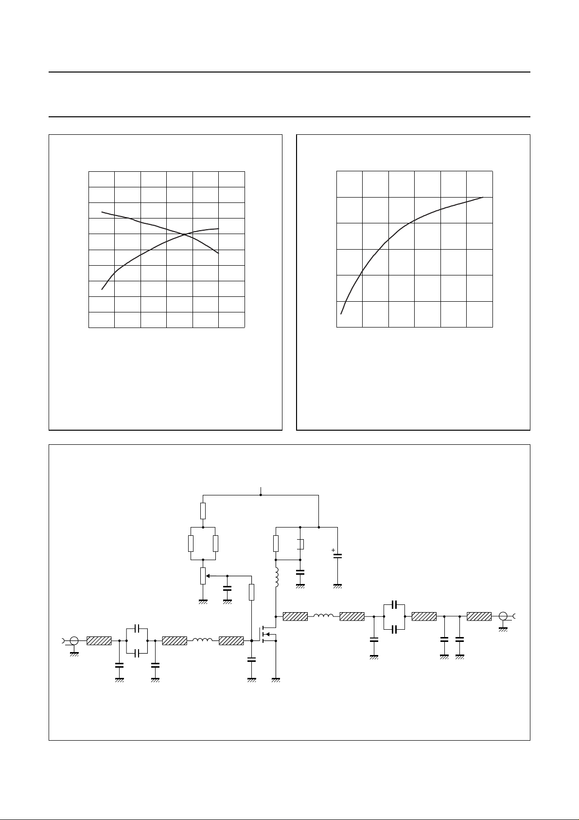
η
PL (W)
MGM520
D
G
p
20
handbook, halfpage
G
p
(dB)
16
12
8
4
0
0246
CW, class-AB operation; f = 500 MHz; VDS= 12.5 V;
= 50 mA; Tmb≤ 60 °C.
I
DQ
Fig.8 Powergain anddrainefficiencyas functions
of load power; typical values.
100
(%)
80
60
40
20
0
η
D
handbook, halfpage
6
P
L
(W)
4
2
0
0
CW, class-AB operation; f = 500 MHz; VDS= 12.5 V;
= 50 mA; Tmb≤ 60 °C.
I
DQ
200 400
MGM521
PD (mW)
600
Fig.9 Load power as a function of drive power;
typical values.
C2
+V
D
R4
L2
R5
DUT
C8
handbook, full pagewidth
input
50 Ω
L5
C4
C5
C6
R3
R1R6R2
L6 L7
L3
C7
Fig.10 Test circuit for class-AB operation at f = 500 MHz.
2003 Sep 26 7
L1
C1
C3
C10
L8
L4
L9
C11
C9
L10 L11
C13C12
output
50 Ω
MGM523
Page 8

Philips Semiconductors Product specification
UHF power MOS transistor BLF404
List of components; see Figs 10 and 11.
COMPONENT DESCRIPTION VALUE DIMENSIONS CATALOGUE NO.
C1 electrolytic capacitor 4.7 µF, 10 V
C2, C3 multilayer ceramic chip capacitor 47 nF
C4 multilayer ceramic chip capacitor; note 1 18 pF
C5, C10 multilayer ceramic chip capacitor; note 1 180 pF
C6, C11 multilayer ceramic chip capacitor; note 1 270 pF
C7 multilayer ceramic chip capacitor; note 1 22 pF
C8 multilayer ceramic chip capacitor; note 1 8.2 pF
C9 multilayer ceramic chip capacitor; note 1 2.7 pF
C12 multilayer ceramic chip capacitor; note 1 1.2 pF
C13 multilayer ceramic chip capacitor; note 1 12 pF
L1 2 turns 1 mm enamelled copper wire on
a grade 4B1 Ferroxcube core
L2 3 turns 1 mm enamelled copper wire int. dia. = 4.6 mm
L3 bifilar coil lead dia. = 0.8 mm
L4 bifilar coil lead dia. = 1 mm
L5 stripline; note 2 50 Ω 8.8 × 2.38 mm
L6 stripline; note 2 50 Ω 5.8 × 2.38 mm
L7 stripline; note 2 50 Ω 6.8 × 2.38 mm
L8 stripline; note 2 50 Ω 3.76 × 2.38 mm
L9 stripline; note 2 50 Ω 5.8 × 2.38 mm
L10 stripline; note 2 50 Ω 4.48 × 2.38 mm
L11 stripline; note 2 50 Ω 3.13 × 2.38 mm
R1, R2 SMD resistor 3.9 kΩ
R3 metal film resistor 1 kΩ, 0.25 W
R4 metal film resistor 22 Ω, 0.25 W
R5 metal film resistor 10 kΩ, 0.25 W
R6 potentiometer 10 kΩ
ext. dia. = 4.2 mm
int. dia.=2mm
length = 6 mm
leads = 2 x 5 mm
Notes
1. American Technical Ceramics type 100A or capacitor of same quality.
2. The striplines are on a double copper-clad printed-circuit board, with DUROID dielectric (εr= 2.2);
thickness 0.79 mm, thickness of the copper sheet 2 x 35 µm.
2003 Sep 26 8
Page 9
Philips Semiconductors Product specification
UHF power MOS transistor BLF404
handbook, full pagewidth
56
31
2
1
3
R6
R1
R2
R3
C2
R5
C5
L5
C6
C4
L3
L6 L8L7 L9 L10
C7
C8
BLF404
+V
D
C1
L1
R4
C3
L2
C9
C10
C11
C12
L11
C13
L4
MGM524
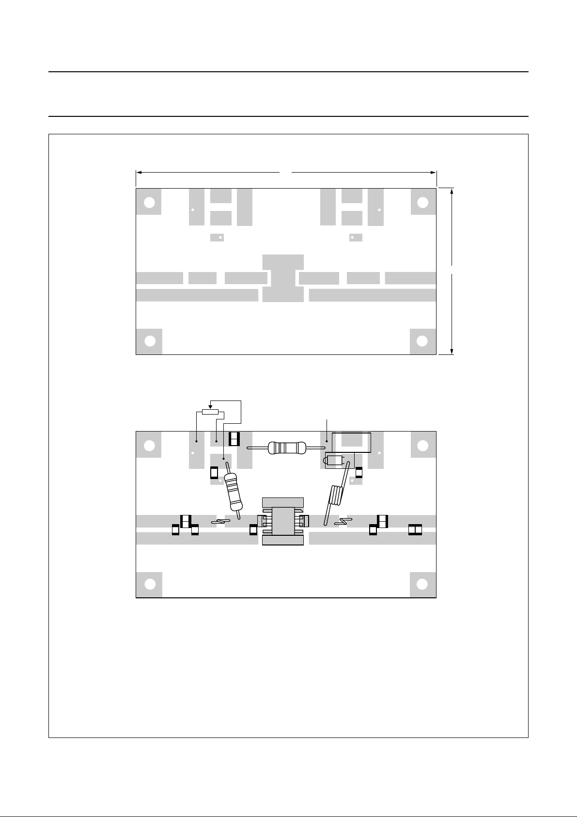
Dimensions in mm.
The components are situated on one side of the copper-clad printed-circuit board, the other side is unetched and serves as a ground plane.
Earth connections from the component side to the ground plane are made by through metallization.
Fig.11 Component layout for 500 MHz class-AB test circuit.
2003 Sep 26 9
Page 10
Philips Semiconductors Product specification
UHF power MOS transistor BLF404
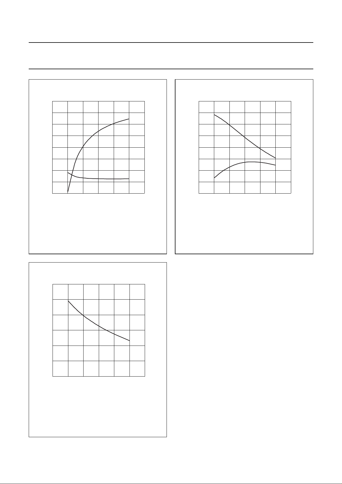
x
i
r
i
f (MHz)
MGM517
handbook, halfpage
8
r
i
(Ω)
6
4
2
0
0 200 400 600
CW, class-AB operation; VDS= 12.5 V; ID=50mA;
= 4 W; Tmb≤ 60 °C.
P
L
Fig.12 Input impedance as a function of frequency
(series components); typical values.
0
x
(Ω)
−20
−40
−60
−80
f (MHz)
MGM518
R
L
X
L
16
handbook, halfpage
i
Z
L
(Ω)
12
8
4
0
0 200 400 600
CW, class-AB operation; VDS= 12.5 V; ID=50mA;
= 4 W; Tmb≤ 60 °C.
P
L
Fig.13 Load impedance as a function of frequency
(series components); typical values.
30
handbook, halfpage
G
p
(dB)
20
10
0
0 200 400 600
CW, class-AB operation; VDS= 12.5 V; IDQ=50mA;
= 4 W; Tmb≤ 60 °C.
P
L
f (MHz)
Fig.14 Power gain as a function of frequency
(series components); typical values.
MGM519
2003 Sep 26 10
Page 11
Philips Semiconductors Product specification
UHF power MOS transistor BLF404
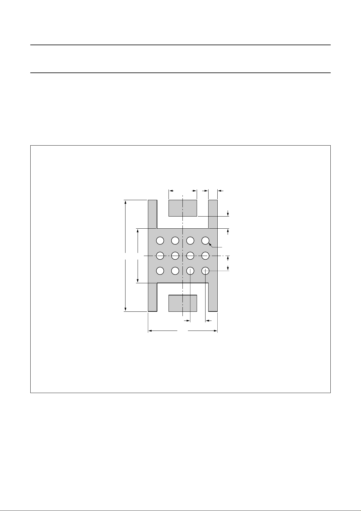
MOUNTING RECOMMENDATIONS
Both the metallized ground plate and the device leads contribute to the heat flow. It is recommended that the transistor
be mounted on a grounded metallized area of the printed-circuit board. This area should be of maximum 0.8 mm
thickness and include at least 12 x 0.5 diameter through metallized holes filled with solder.
A thermal resistanceR
th(mb-h)
on the printed-circuit board.
handbook, full pagewidth
of 5 K/W canbe achieved if heatsink compound is applied when the transistor is mounted
1.87 (2×)
3.607.38
0.60 (4×)
0.80 (2×)
0.50 (12×)
1.00 (8×)
4.60
Dimensions in mm.
Fig.15 Reflow soldering footprint for SOT409A.
2003 Sep 26 11
1.00 (9×)
MGK390
Page 12

Philips Semiconductors Product specification
UHF power MOS transistor BLF404
BLF404 scattering parameters
VDS= 12.5 V; ID= 50 mA; note 1.
f (MHz)
s
11
s
21
s
12
s
22
|s11| ∠Φ |s21| ∠Φ |s12| ∠Φ |s22| ∠Φ
5 1.00 −5.2 12.97 176.0 0.01 86.0 0.96 −6.0
10 0.99 −10.1 12.89 171.9 0.02 82.2 0.96 −12.0
20 0.98 −20.6 12.61 164.1 0.03 74.8 0.95 −23.5
30 0.96 −30.4 12.18 156.6 0.05 67.6 0.93 −34.7
40 0.93 −39.6 11.62 149.6 0.06 60.9 0.91 −45.1
50 0.89 −48.0 11.00 143.2 0.07 54.8 0.89 −54.7
60 0.86 −55.8 10.37 137.4 0.08 49.4 0.87 −63.5
70 0.83 −62.9 9.74 132.2 0.09 44.4 0.85 −71.4
80 0.80 −69.4 9.15 127.5 0.10 40.1 0.83 −78.5
90 0.78 −75.3 8.60 123.2 0.10 36.2 0.82 −84.8
100 0.75 −80.7 8.08 119.3 0.10 32.7 0.80 −90.5
125 0.71 −92.2 6.96 110.7 0.11 25.1 0.77 −102.6
150 0.68 −101.4 6.03 103.9 0.12 19.1 0.76 −111.9
175 0.66 −108.9 5.30 98.3 0.12 14.4 0.74 −119.2
200 0.64 −115.2 4.73 93.2 0.12 10.2 0.74 −125.1
250 0.63 −124.9 3.81 84.5 0.12 3.5 0.73 −134.1
300 0.64 −132.5 3.19 77.4 0.12 −1.8 0.74 −140.5
350 0.64 −138.6 2.70 71.2 0.11 −6.1 0.74 −145.3
400 0.66 −143.8 2.34 65.7 0.11 −9.7 0.75 −149.1
450 0.67 −148.4 2.03 60.5 0.10 −12.5 0.76 −152.4
500 0.69 −152.6 1.80 56.0 0.09 −15.1 0.78 −155.2
600 0.72 −160.2 1.44 47.7 0.08 −18.2 0.80 −159.9
700 0.75 −167.1 1.18 40.4 0.07 −18.6 0.82 −163.9
800 0.78 −173.6 0.99 34.4 0.05 −15.0 0.84 −167.5
900 0.81 −179.8 0.84 29.2 0.04 -6.0 0.86 −170.7
1000 0.83 174.3 0.73 25.1 0.04 9.9 0.88 −173.6
Note
1. For more extensive s-parameters see internet:
http://www.semiconductors.philips.com/markets/communications/wirelesscommunications/broadcast
2003 Sep 26 12
Page 13
Philips Semiconductors Product specification
UHF power MOS transistor BLF404
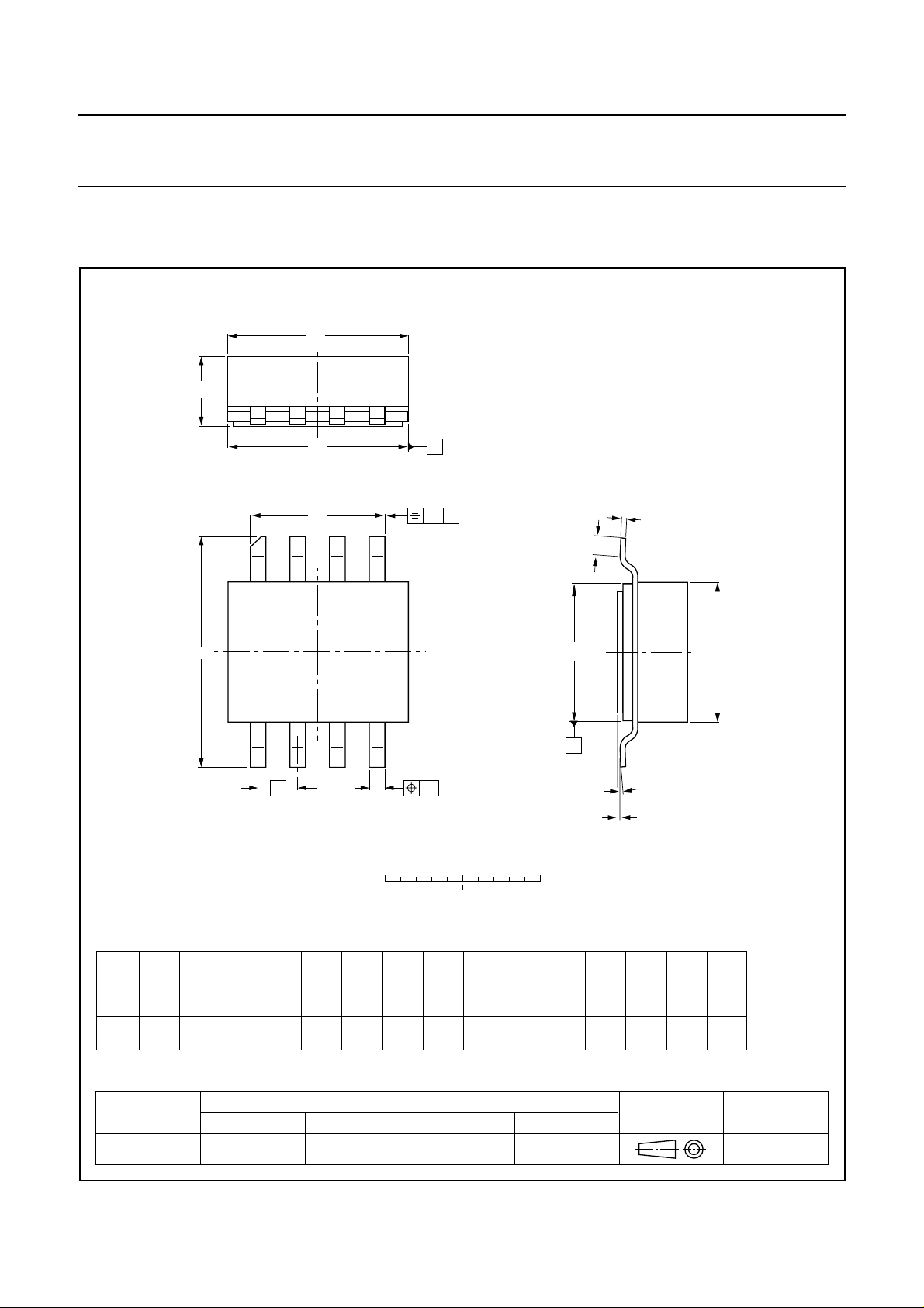
PACKAGE OUTLINE
Ceramic surface mounted package; 8 leads SOT409A
D
A
D
2
H
1
85
H
14
e
b
0 2.5 5 mm
B
w
B
2
w
1
scale
c
L
E
2
A
α
Q
1
E
DIMENSIONS (millimetre dimensions are derived from the original inch dimensions)
UNIT cbDE
mm
inches
A
2.36
2.06
0.093
0.081
OUTLINE
VERSION
SOT409A
0.58
0.43
0.023
0.017
D
2
0.23
5.94
5.03
0.234
0.198
5.16
5.00
0.203
0.197
0.194
0.158
0.18
0.009
0.007
IEC JEDEC EIAJ
E
4.93
4.14
4.01
3.99
0.163
0.157
REFERENCES
2
1.27
0.050
e
HH
7.47
7.26
0.294
0.286
2003 Sep 26 13
1
4.39
4.24
0.173
0.167
LQ
1.02
0.10
0.51
0.00
0.040
0.004
0.020
0.000
1
0.25
0.010
PROJECTION
w
w
1
0.25
0.010
EUROPEAN
2
α
7°
0°
7°
0°
ISSUE DATE
98-01-27
Page 14

Philips Semiconductors Product specification
UHF power MOS transistor BLF404
DATA SHEET STATUS
LEVEL
DATA SHEET
STATUS
(1)
PRODUCT
STATUS
(2)(3)
DEFINITION
I Objective data Development This data sheet contains data from the objective specification for product
development. Philips Semiconductors reserves the right to change the
specification in any manner without notice.
II Preliminary data Qualification This data sheet contains data from the preliminary specification.
Supplementary data will be published at a later date. Philips
Semiconductors reserves the right to change the specification without
notice, in order to improve the design and supply the best possible
product.
III Product data Production This data sheet contains data from the product specification. Philips
Semiconductors reserves the right to make changes at any time in order
to improve the design, manufacturing and supply. Relevant changes will
be communicated via a Customer Product/Process Change Notification
(CPCN).
Notes
1. Please consult the most recently issued data sheet before initiating or completing a design.
2. The product status of the device(s) described in this data sheet may have changed since this data sheet was
published. The latest information is available on the Internet at URL http://www.semiconductors.philips.com.
3. For datasheets describingmultiple type numbers,the highest-levelproduct status determinesthe datasheet status.
DEFINITIONS
DISCLAIMERS
Short-form specification The data in a short-form
specification is extracted from a full data sheet with the
same type number and title. For detailed information see
the relevant data sheet or data handbook.
Limiting valuesdefinition Limiting values givenare in
accordance with the Absolute Maximum Rating System
(IEC 60134). Stress above one or more of the limiting
values may cause permanent damage to the device.
These are stress ratings only and operation of the device
atthese orat any otherconditions abovethosegiven inthe
Characteristics sectionsof the specification isnot implied.
Exposure to limiting values for extended periods may
affect device reliability.
Application information Applications that are
described herein for any of these products are for
illustrative purposes only. Philips Semiconductors make
norepresentation orwarranty thatsuchapplications willbe
suitable for the specified use without further testing or
modification.
Life support applications These products are not
designed for use in life support appliances, devices, or
systems where malfunction of these products can
reasonably be expected to result in personal injury.Philips
Semiconductorscustomers usingor sellingtheseproducts
for use in such applications do so at their own risk and
agree to fully indemnify Philips Semiconductors for any
damages resulting from such application.
Right to make changes Philips Semiconductors
reserves the right to make changes in the products including circuits, standard cells, and/or software described or contained herein in order to improve design
and/or performance. When theproduct isin fullproduction
(status ‘Production’), relevant changes will be
communicated via a Customer Product/Process Change
Notification (CPCN). Philips Semiconductors assumes no
responsibility or liability for the use of any of these
products, conveys no licence or title under any patent,
copyright, or mask work right to these products, and
makes no representations or warranties that these
products are free from patent, copyright, or mask work
right infringement, unless otherwise specified.
2003 Sep 26 14
Page 15

Philips Semiconductors – a w orldwide compan y
Contact information
For additional information please visit http://www.semiconductors.philips.com. Fax: +31 40 27 24825
For sales offices addresses send e-mail to: [email protected].
© Koninklijke Philips Electronics N.V. 2003
All rights are reserved. Reproduction in whole or in part is prohibited without the prior written consent of the copyright owner.
The information presented in thisdocument does not form partof any quotation or contract, is believed to be accurate and reliable and may be changed
without notice. No liability will be accepted by the publisher for any consequence of its use. Publication thereof does not convey nor imply any license
under patent- or other industrial or intellectual property rights.
Printed in The Netherlands 613524/04/pp15 Date of release: 2003 Sep26 Document order number: 9397 75011603
SCA75
 Loading...