

Page 1
DISCRETE SEMICONDUCTORS
DATA SH EET
M3D065
BLF242
HF-VHF power MOS transistor
Product specification
Supersedes data of 1997 Dec 17
2003 Oct 13
Page 2
Philips Semiconductors Product specification
HF-VHF power MOS transistor BLF242
FEATURES
• High power gain
• Low noise
• Easy power control
• Good thermal stability
• Withstands full load mismatch
• Gold metallization ensures
excellent reliability.
DESCRIPTION
Silicon N-channel enhancement
mode vertical D-MOS transistor
designed for professional transmitter
applicationsintheHF/VHF frequency
range.
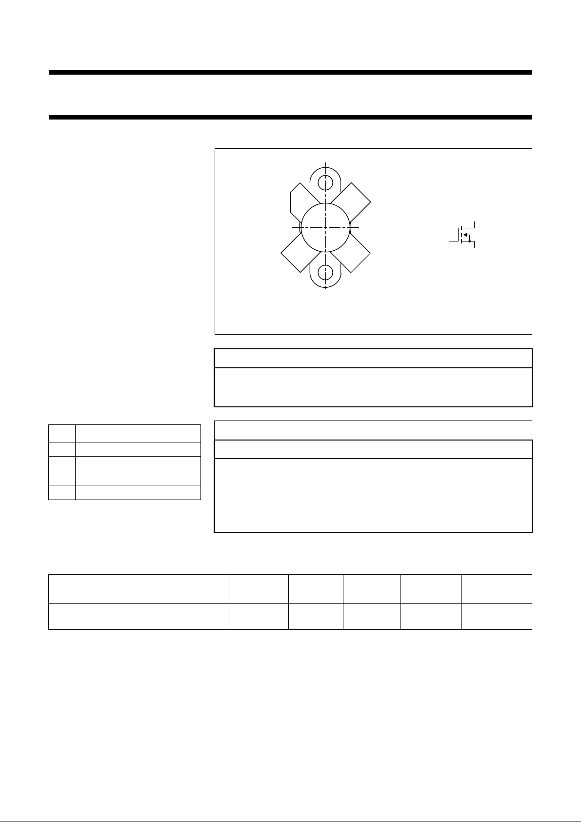
The transistor is encapsulated in a
4-lead, SOT123A flange package,
with a ceramic cap. All leads are
isolated from the flange.
PINNING - SOT123A
PIN DESCRIPTION
1 drain
2 source
3 gate
4 source
PIN CONFIGURATION
handbook, halfpage
1
23
4
MSB057
g
MBB072
d
s
Fig.1 Simplified outline and symbol.
CAUTION
This product is supplied in anti-static packing to prevent damage caused by
electrostaticdischarge duringtransport andhandling.For furtherinformation,
refer to Philips specs.: SNW-EQ-608, SNW-FQ-302A, and SNW-FQ-302B.
WARNING
Product and environmental safety - toxic materials
This product contains beryllium oxide. The product is entirely safe provided
that theBeO disc isnot damaged. All personswho handle, useor dispose of
this product should be aware of its nature and of the necessary safety
precautions. After use,dispose of as chemical orspecial waste according to
the regulations applying at the location of the user. It must never be thrown
out with the general or domestic waste.
QUICK REFERENCE DATA
RF performance at Th = 25 °C in a common source test circuit.
MODE OF OPERATION
f
(MHz)
V
(V)
DS
P
(W)
L
(dB)
CW, class-B 175 28 5 >13
typ. 16
2003 Oct 13 2
G
p
η
D
(%)
>50
typ. 60
Page 3
Philips Semiconductors Product specification
HF-VHF power MOS transistor BLF242
LIMITING VALUES
In accordance with the Absolute Maximum Rating System (IEC 60134).
SYMBOL PARAMETER CONDITIONS MIN. MAX. UNIT
V
DS
V
GS
I
D
P
tot
T
stg
T
j
THERMAL CHARACTERISTICS
SYMBOL PARAMETER CONDITIONS VALUE UNIT
R
th j-mb
R
th mb-h
drain-source voltage − 65 V
gate-source voltage −±20 V
drain current (DC) − 1A
total power dissipation Tmb≤ 25 °C − 16 W
storage temperature −65 150 °C
junction temperature − 200 °C
thermal resistance from junction to
Tmb=25°C; P
= 16 W 11 K/W
tot
mounting base
thermal resistance from mounting base to
Tmb=25°C; P
= 16 W 0.3 K/W
tot
heatsink
10
handbook, halfpage
I
D
(A)
1
(1)
−1
10
−2
10
1
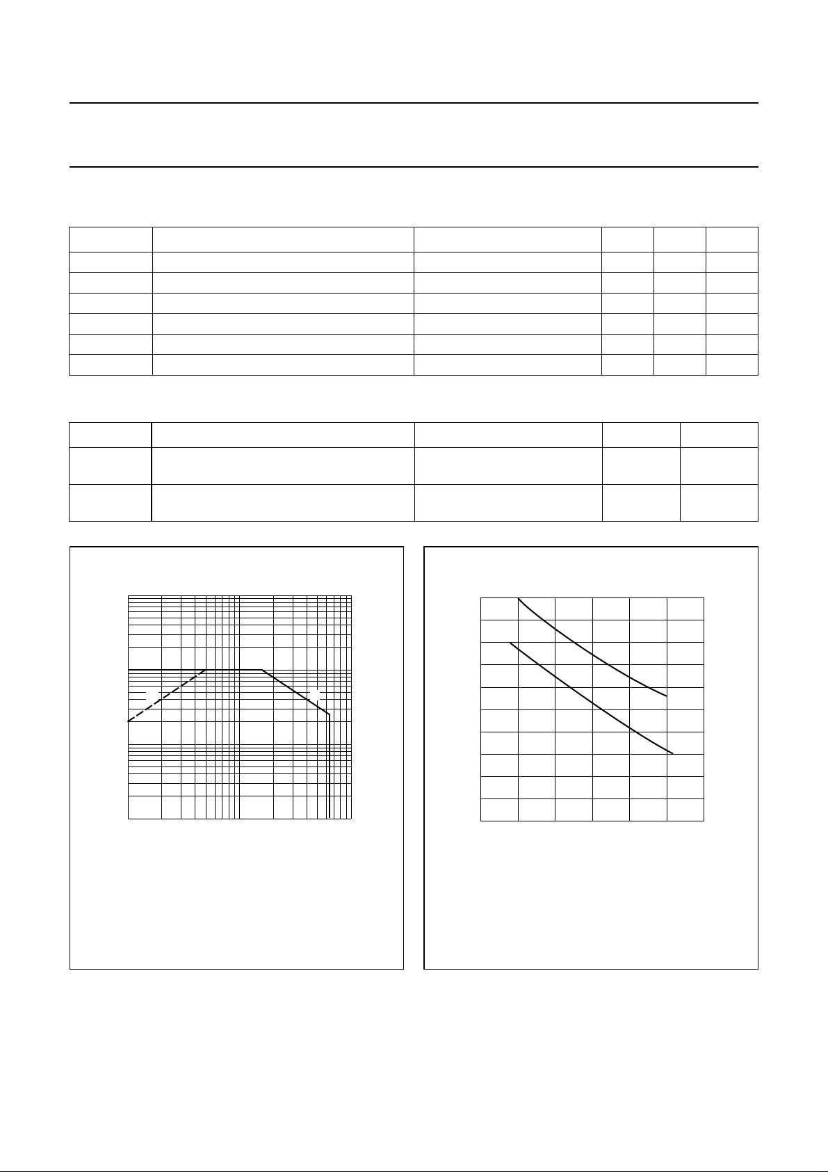
(1) Current is this area may be limited by R
(2) Tmb=25°C.
10
Fig.2 DC SOAR.
VDS (V)
.
DSon
(2)
MRA918
20
handbook, halfpage
P
tot
(W)
10
2
10
0
0 50 100 150
(1) Continuous operation.
(2) Short-time operation during mismatch.
(2)
(1)
MPG141
Th (°C)
Fig.3 Power derating curves.
2003 Oct 13 3
Page 4
Philips Semiconductors Product specification
HF-VHF power MOS transistor BLF242
CHARACTERISTICS
Tj = 25 °C unless otherwise specified.
SYMBOL PARAMETER CONDITIONS MIN. TYP. MAX. UNIT
V
(BR)DSS
I
DSS
I
GSS
V
GSth
g
fs
R
DSon
I
DSX
C
is
C
os
C
rs
drain-source breakdown voltage VGS = 0; ID= 0.1 mA 65 −− V
drain-source leakage current VGS = 0; VDS = 28 V −−10 µA
gate-source leakage current VGS = ±20 V; VDS = 0 −−1 µA
gate-source threshold voltage ID = 3 mA; VDS = 10 V 2 − 4.5 V
forward transconductance ID = 0.3 A; VDS = 10 V 0.16 0.24 − S
drain-source on-state resistance ID = 0.3 A; VGS = 1 V − 3.3 5 Ω
on-state drain current VGS = 10 V; VGS = 10 V − 1.2 − A
input capacitance VGS = 0; VDS = 28 V; f = 1 MHz − 13 − pF
output capacitance VGS = 0; VDS = 28 V; f = 1 MHz − 9.4 − pF
feedback capacitance VGS = 0; VDS = 28 V; f = 1 MHz − 1.7 − pF
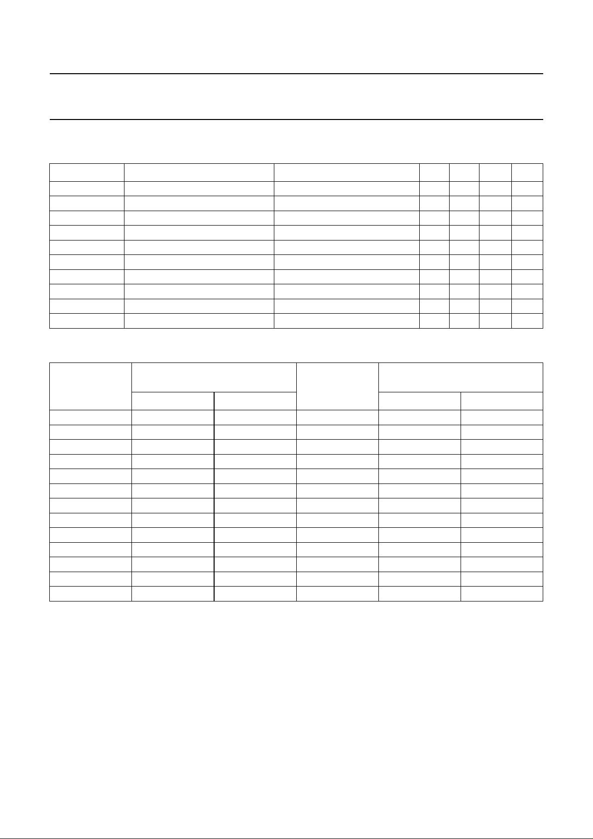
VGS group indicator
GROUP
A 2.0 2.1 O 3.3 3.4
B 2.1 2.2 P 3.4 3.5
C 2.2 2.3 Q 3.5 3.6
D 2.3 2.4 R 3.6 3.7
E 2.4 2.5 S 3.7 3.8
F 2.5 2.6 T 3.8 3.9
G 2.6 2.7 U 3.9 4.0
H 2.7 2.8 V 4.0 4.1
J 2.8 2.9 W 4.1 4.2
K 2.9 3.0 X 4.2 4.3
L 3.0 3.1 Y 4.3 4.4
M 3.1 3.2 Z 4.4 4.5
N 3.2 3.3
LIMITS
(V)
GROUP
LIMITS
(V)
MIN. MAX. MIN. MAX.
2003 Oct 13 4
Page 5
Philips Semiconductors Product specification
HF-VHF power MOS transistor BLF242
handbook, halfpage
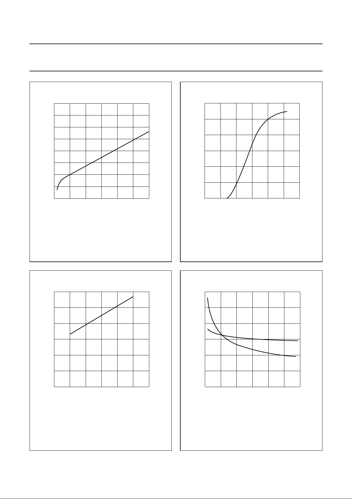
4
T.C.
(mV/K)
2
0
–2
–4
0 100 200 300
VDS=10V.
ID (mA)
Fig.4 Temperature coefficient of gate-source
voltageas afunctionof draincurrent,typical
values.
MBB777
1.5
handbook, halfpage
I
D
(A)
1
0.5
0
0
VDS= 10 V; Tj=25°C.
51015
MGP142
VGS (V)
Fig.5 Drain current as a function of gate-source
voltage, typical values.
handbook, halfpage
6
R
DS (on)
(Ω)
4
2
0
0
ID= 0.3 A; VGS=10V.
50 100 150
Tj (oC)
Fig.6 Drain-source on-state resistance as a
function of junction temperature, typical
values.
MBB778
30
handbook, halfpage
C
(pF)
20
10
0
0
VGS= 0; f = 1 MHz.
C
is
C
os
10 20 30
MBB776
VDS (V)
Fig.7 Input andoutput capacitanceas functions
of drain-source voltage, typical values.
2003 Oct 13 5
Page 6
Philips Semiconductors Product specification
HF-VHF power MOS transistor BLF242
handbook, halfpage
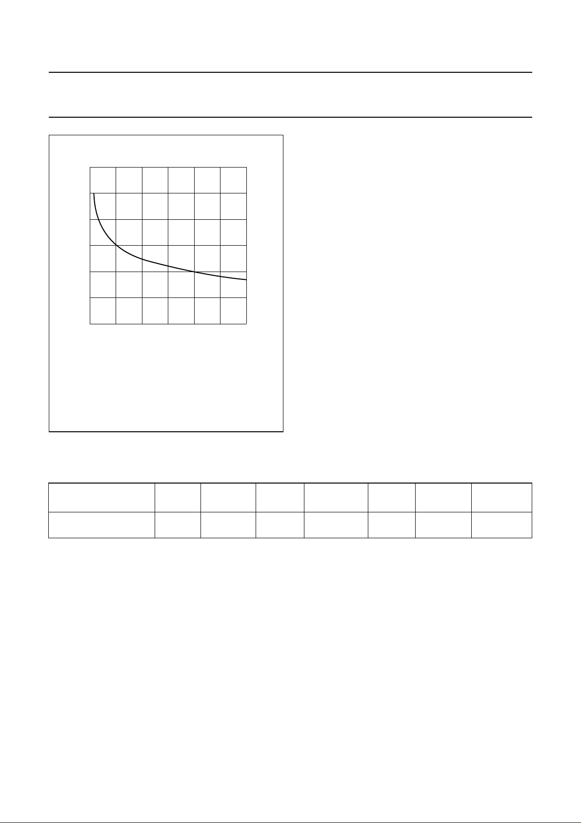
6
C
rs
(pF)
4
2
0
0
VGS= 0; f = 1 MHz.
10 20 30
VDS (V)
Fig.8 Feedback capacitance as a function of
drain-source voltage, typical values.
MBB775
APPLICATION INFORMATION FOR CLASS-B OPERATION
Th=25°C; R
= 0.3 K/W; unless otherwise specified.
th mb-h
RF performance in CW operation in a common source class-B test circuit.
MODE OF OPERATION
f
(MHz)
V
(V)
DS
I
DQ
(mA)
CW, class-B 175 28 10 5 >13
P
(W)
L
G
P
(dB)
typ. 16
η
D
(%)
>50
typ. 60
R
(Ω)
GS
47
Ruggedness in class-B operation
The BLF242 is capable of withstanding a load mismatch corresponding to VSWR = 50 through all phases under the
following conditions: V
= 28 V; f =175 MHz at rated output power.
DS
Noise figure (see Fig.11)
VDS= 28 V; ID= 0.2 A; f = 175 MHz; RGS=47Ω; Th=25°C. Input and output power matched for PL=5W;
F = typ. 5.5 dB.
2003 Oct 13 6
Page 7
Philips Semiconductors Product specification
HF-VHF power MOS transistor BLF242
20
handbook, halfpage
G
p
(dB)
10
0
0510
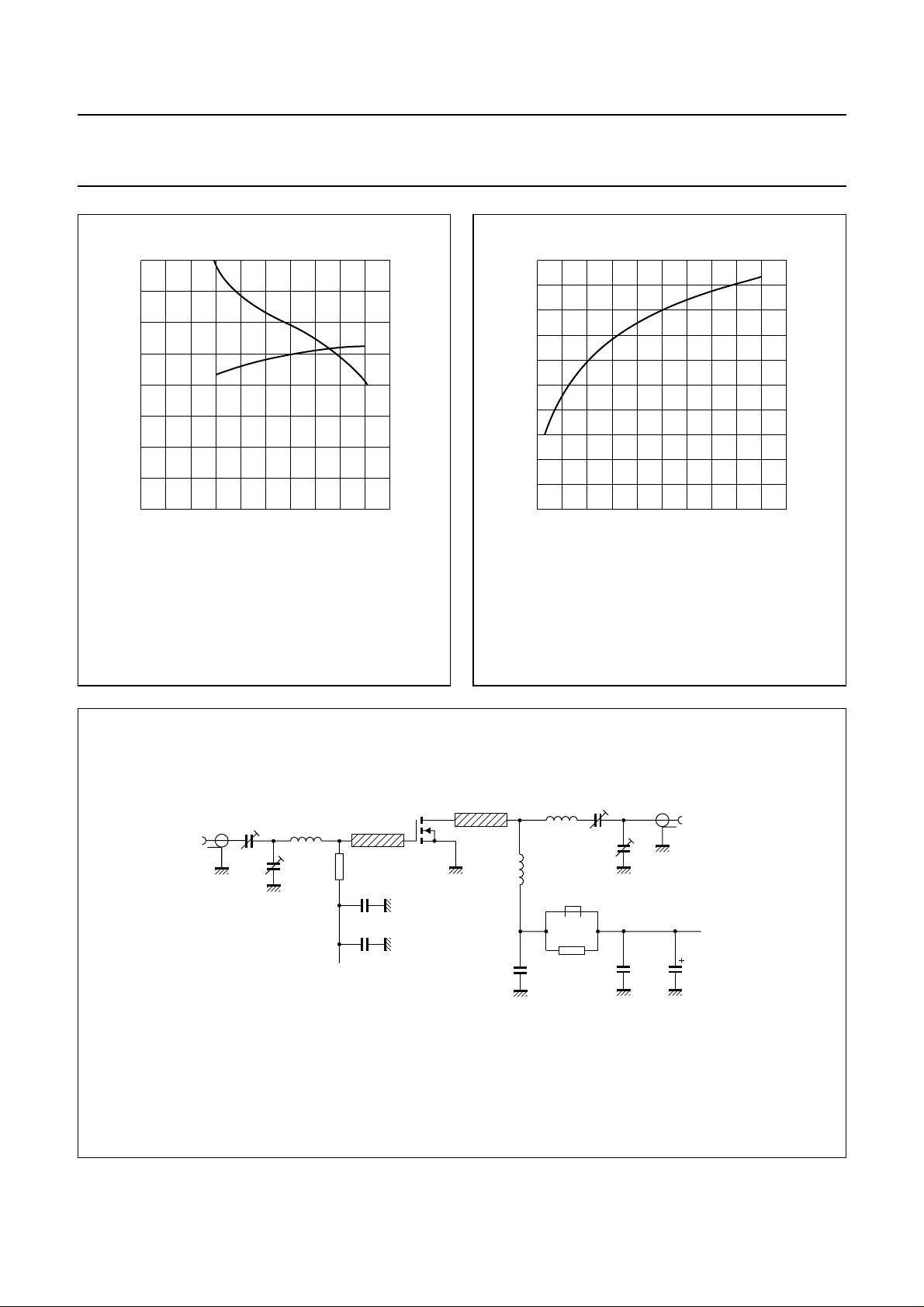
Class-B operation; VDS= 28 V; IDQ=10mA;
=47Ω; f = 175 MHz.
R
GS
G
p
η
d
MGP143
PL (W)
Fig.9 Power gain and efficiency as functions of
load power, typical values.
100
η
(%)
50
0
IN
MGP144
(W)
10
handbook, halfpage
d
P
L
(W)
5
0
0 0.5 1
Class-B operation; VDS= 28 V; IDQ=10mA;
=47Ω; f = 175 MHz.
R
GS
P
Fig.10 Load power as a function of input power,
typical values.
handbook, full pagewidth
input
50 Ω
f = 175 MHz.
C1
C2
L1
R1
C3
C3
+V
G
D.U.T.
L2
Fig.11 Test circuit for class-B operation.
2003 Oct 13 7
L3
L4
C5
C6
L5
C7
L6
R2
C8
output
50 Ω
C9
MGP145
+V
D
Page 8

Philips Semiconductors Product specification
HF-VHF power MOS transistor BLF242
List of components (see Fig.11)
COMPONENT DESCRIPTION VALUE DIMENSIONS CATALOGUE NO.
C1, C2, C7 film dielectric trimmer 4 to 40 pF 2222 809 08002
C3 multilayer ceramic chip capacitor; note 1 100 pF
C4, C8 ceramic chip capacitor 100 nF 2222 852 47104
C6 film dielectric trimmer 5 to 60 pF 2222 809 08003
C9 electrolytic capacitor 2.2 µF, 40 V
L1 5 turns enamelled 0.7 mm copper wire 53 nH length 5.4 mm
int. dia. 3 mm
leads 2 × 5mm
L2, L3 stripline; note 2 30 Ω 10 × 6mm
L4 11 turns enamelled 1 mm copper wire 500 nH length 15.5 mm
int. dia. 8 mm
leads 2 × 5mm
L5 5 turns enamelled 1 mm copper wire 79 nH length 9.1 mm
int. dia. 5 mm
leads 2 × 5mm
L6 grade 3B Ferroxcube RF choke 4312 020 36640
R1 0.5 W metal film resistor 47 Ω
R2 0.5 W metal film resistor 10 Ω
Notes
1. American Technical Ceramics (ATC) capacitor, type 100B or other capacitor of the same quality.
2. The striplines are on a double copper-clad printed circuit board, with epoxy fibre-glass dielectric (εr= 4.5),
thickness1⁄16inch.
2003 Oct 13 8
Page 9
Philips Semiconductors Product specification
HF-VHF power MOS transistor BLF242
handbook, full pagewidth
strap
C1
rivet
C2
+V
150
strap
70
L6
+V
C5
R2
G
R1
L1
C3
C4
L2 L3
L4
C8
L5
D
C9
C6
C7
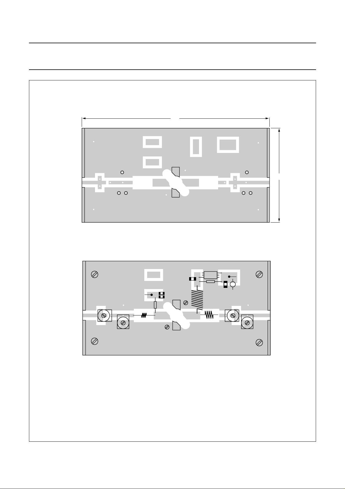
Dimensions in mm.
The circuit and components are situated on one side of the epoxy fibre-glass board, the other side being fully
metallized to serve asearth.Earth connections are made byfixingscrews, copper straps andhollowrivets at the
edges of the board and under the source.
Fig.12 Component layout for 175 MHz class-B test circuit.
2003 Oct 13 9
MGP146
Page 10
Philips Semiconductors Product specification
HF-VHF power MOS transistor BLF242
50
handbook, halfpage
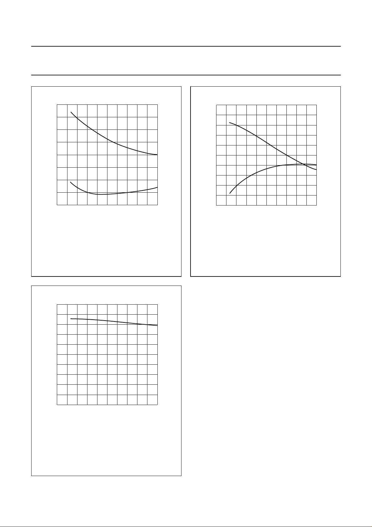
Z
i
(Ω)
30
10
−10
−30
0
Class-B operation; VDS= 28 V; PL=30W;
=47Ω;Th=25°C.
R
GS
r
i
x
i
100
MGP150
f (MHz)
Fig.13 Input impedance as afunction of frequency
(series components), typical values.
200
100
handbook, halfpage
Z
L
(Ω)
50
0
0 200
Class-B operation; VDS= 28 V; PL=30W;
=47Ω;Th=25°C.
R
GS
R
L
X
L
100
MGP149
f (MHz)
Fig.14 Load impedance as afunction of frequency
(series components), typical values.
20
handbook, halfpage
G
p
(dB)
10
0
0 200
Class-B operation; VDS= 28 V; PL=30W;
=47Ω;Th=25°C.
R
GS
100
f (MHz)
Fig.15 Power gain as a function of frequency,
typical values.
MGP148
2003 Oct 13 10
Page 11
Philips Semiconductors Product specification
HF-VHF power MOS transistor BLF242
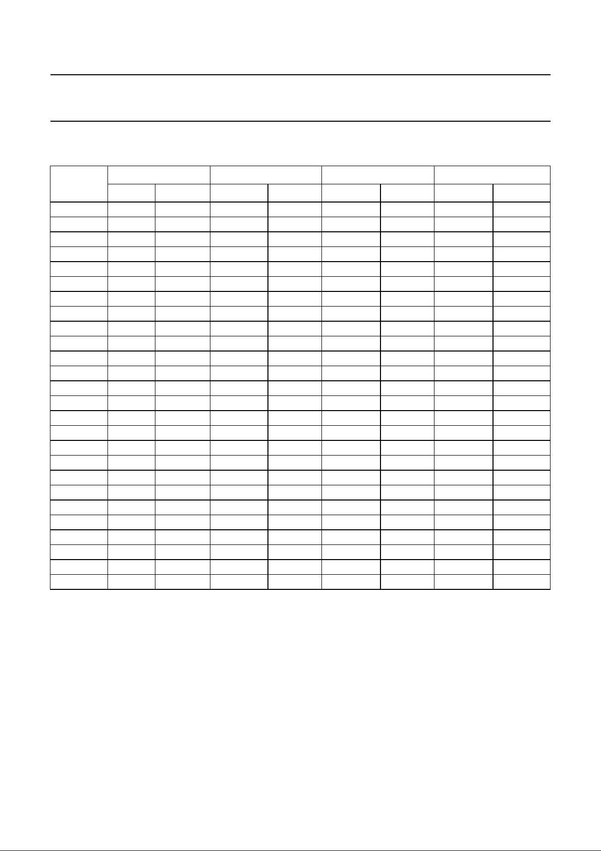
BLF242 scattering parameters
VDS= 28 V; ID= 10 mA; note 1
f (MHz)
s
11
s
21
s
12
s
22
|s11| ∠Φ |s21| ∠Φ |s12| ∠Φ |s22| ∠Φ
5 0.99 −3.40 5.57 177.10 0.01 87.60 1.00 −2.60
10 0.98 −5.80 5.52 175.10 0.01 85.50 1.00 −5.30
20 0.99 −12.40 5.53 169.40 0.02 80.70 0.99 −10.70
30 0.98 −17.90 5.46 164.90 0.03 76.50 0.99 −16.10
40 0.97 −24.10 5.40 159.80 0.04 71.80 0.98 −21.30
50 0.96 −30.10 5.30 154.80 0.05 67.2 0.97 −26.30
60 0.95 −36.10 5.17 149.80 0.06 62.90 0.95 −31.20
70 0.93 −41.60 5.01 145.10 0.06 58.70 0.94 −35.80
80 0.92 −46.40 4.83 141.00 0.07 55.10 0.93 −40.20
90 0.91 −50.90 4.68 137.30 0.08 51.80 0.92 −44.50
100 0.90 −55.20 4.55 133.60 0.08 48.50 0.90 −48.70
125 0.87 −66.60 4.23 124.20 0.09 40.10 0.87 −58.40
150 0.84 −76.70 3.85 115.60 0.10 32.70 0.84 −66.60
175 0.82 −85.00 3.51 108.60 0.10 27.20 0.82 −74.00
200 0.81 −92.70 3.23 102.10 0.11 22.00 0.81 −80.90
250 0.78 −106.30 2.72 89.90 0.10 12.50 0.78 −92.10
300 0.78 −117.30 2.33 80.30 0.10 6.10 0.78 −101.80
350 0.77 −126.90 2.00 71.40 0.09 1.00 0.78 −109.70
400 0.78 −135.60 1.74 63.90 0.08 −1.50 0.79 −116.80
450 0.79 −143.20 1.53 56.80 0.06 −1.80 0.80 −123.00
500 0.79 −150.30 1.36 51.00 0.05 2.10 0.81 −128.80
600 0.81 −163.30 1.09 40.80 0.03 33.70 0.84 −139.00
700 0.82 −175.10 0.89 32.70 0.05 74.30 0.86 −147.90
800 0.83 173.80 0.74 26.80 0.08 87.20 0.87 −155.90
900 0.83 163.20 0.63 23.00 0.11 86.30 0.89 −162.90
1000 0.83 152.90 0.54 21.70 0.28 144.80 0.65 175.60
Note
1. For more extensive s-parameters see internet:
http://www.semiconductors.philips.com/markets/communications/wirelesscommunication/broadcast.
2003 Oct 13 11
Page 12
Philips Semiconductors Product specification
HF-VHF power MOS transistor BLF242
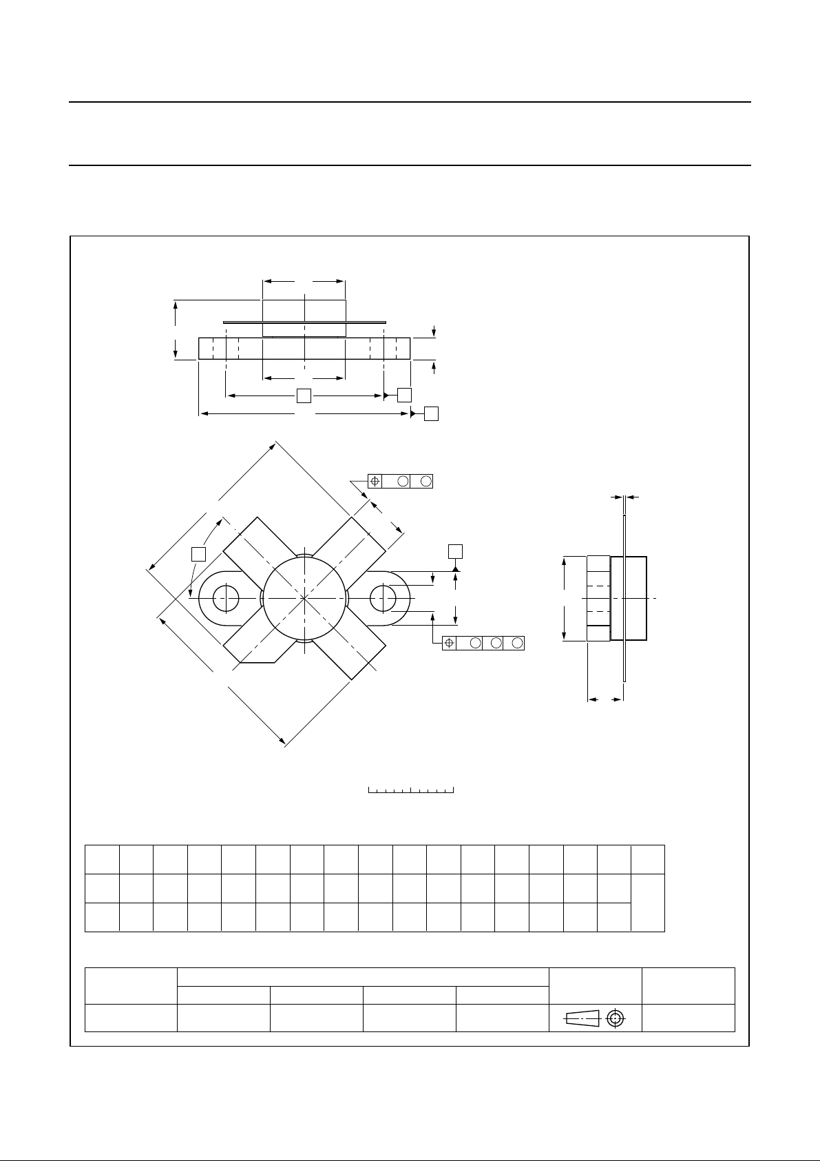
PACKAGE OUTLINE
Flanged ceramic package; 2 mounting holes; 4 leads SOT123A
D
A
F
D
1
H
43
α
q
U
1
C
B
w
C
M M
2
b
A
c
U
p
2
1
w
2
H
0 5 10 mm
scale
DIMENSIONS (millimetre dimensions are derived from the original inch dimensions)
5.82
5.56
c
Db
9.73
0.18
9.47
0.10
0.385
0.383
0.007
0.004
IEC JEDEC EIAJ
0.373
0.371
D
9.78
9.42
F
1
20.71
2.72
2.31
0.107
0.091
3.33
19.93
3.04
0.815
0.131
0.785
0.120
REFERENCES
Q
4.63
4.11
q
18.42
0.725
pH
0.182
0.162
UNIT
mm
inches
A
7.47
6.37
0.294
0.251
OUTLINE
VERSION
SOT123A
0.229
0.219
MM
1
24.87
24.64
0.980
0.970
M
A
B
U2U
1
6.48
9.78
6.22
9.39
0.255
0.385
0.245
0.370
U
3
Q
w
w
1
3
0.510.25
0.0200.010
EUROPEAN
PROJECTION
αU
2
45°
ISSUE DATE
99-03-29
2003 Oct 13 12
Page 13

Philips Semiconductors Product specification
HF-VHF power MOS transistor BLF242
DATA SHEET STATUS
LEVEL
DATA SHEET
STATUS
(1)
PRODUCT
STATUS
(2)(3)
DEFINITION
I Objective data Development This data sheet contains data from the objective specification for product
development. Philips Semiconductors reserves the right to change the
specification in any manner without notice.
II Preliminary data Qualification This data sheet contains data from the preliminary specification.
Supplementary data will be published at a later date. Philips
Semiconductors reserves the right to change the specification without
notice, in order to improve the design and supply the best possible
product.
III Product data Production This data sheet contains data from the product specification. Philips
Semiconductors reserves the right to make changes at any time in order
to improve the design, manufacturing and supply. Relevant changes will
be communicated via a Customer Product/Process Change Notification
(CPCN).
Notes
1. Please consult the most recently issued data sheet before initiating or completing a design.
2. The product status of the device(s) described in this data sheet may have changed since this data sheet was
published. The latest information is available on the Internet at URL http://www.semiconductors.philips.com.
3. Fordata sheets describingmultiple typenumbers, the highest-levelproduct status determinesthe datasheet status.
DEFINITIONS
DISCLAIMERS
Short-form specification The data in a short-form
specification is extracted from a full data sheet with the
same type number and title. For detailed information see
the relevant data sheet or data handbook.
Limiting valuesdefinition Limiting values givenare in
accordance with the Absolute Maximum Rating System
(IEC 60134). Stress above one or more of the limiting
values may cause permanent damage to the device.
These are stress ratings only and operation of the device
atthese orat anyotherconditions abovethose givenin the
Characteristics sectionsof the specification isnot implied.
Exposure to limiting values for extended periods may
affect device reliability.
Application information Applications that are
described herein for any of these products are for
illustrative purposes only. Philips Semiconductors make
norepresentation orwarrantythat suchapplicationswill be
suitable for the specified use without further testing or
modification.
Life support applications These products are not
designed for use in life support appliances, devices, or
systems where malfunction of these products can
reasonably beexpected toresult inpersonal injury.Philips
Semiconductorscustomers usingorselling theseproducts
for use in such applications do so at their own risk and
agree to fully indemnify Philips Semiconductors for any
damages resulting from such application.
Right to make changes Philips Semiconductors
reserves the right to make changes in the products including circuits, standard cells, and/or software described or contained herein in order to improve design
and/or performance.When theproduct isin full production
(status ‘Production’), relevant changes will be
communicated via a Customer Product/Process Change
Notification (CPCN). Philips Semiconductorsassumes no
responsibility or liability for the use of any of these
products, conveys no licence or title under any patent,
copyright, or mask work right to these products, and
makes no representations or warranties that these
products are free from patent, copyright, or mask work
right infringement, unless otherwise specified.
2003 Oct 13 13
Page 14

Philips Semiconductors – a w orldwide compan y
Contact information
For additional information please visit http://www.semiconductors.philips.com. Fax: +31 40 27 24825
For sales offices addresses send e-mail to: [email protected].
© Koninklijke Philips Electronics N.V. 2003
All rights are reserved. Reproduction in whole or in part is prohibited without the prior written consent of the copyright owner.
The information presented in this document doesnot form part of any quotation orcontract, is believed to be accurate andreliable and may be changed
without notice. No liability will be accepted by the publisher for any consequence of its use. Publication thereof does not convey nor imply any license
under patent- or other industrial or intellectual property rights.
Printed in The Netherlands 613524/03/pp14 Date of release: 2003Oct 13 Document order number: 9397 750 11583
SCA75
 Loading...