

Page 1
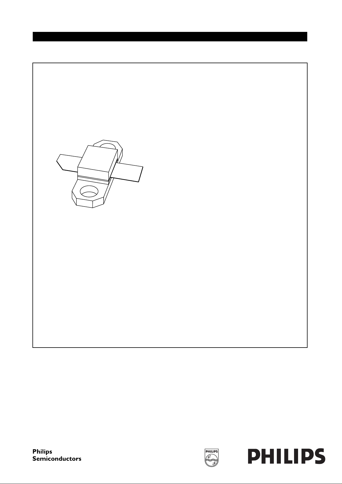
DISCRETE SEMICONDUCTORS
DATA SH EET
M3D381
BLF1046
UHF power LDMOS transistor
Product specification
Supersedes data of 2000 Oct 04
2000 Dec 20
Page 2
Philips Semiconductors Product specification
UHF power LDMOS transistor BLF1046
FEATURES
• High power gain
• Easy power control
• Excellent ruggedness
• Source on underside eliminates DC isolators, reducing
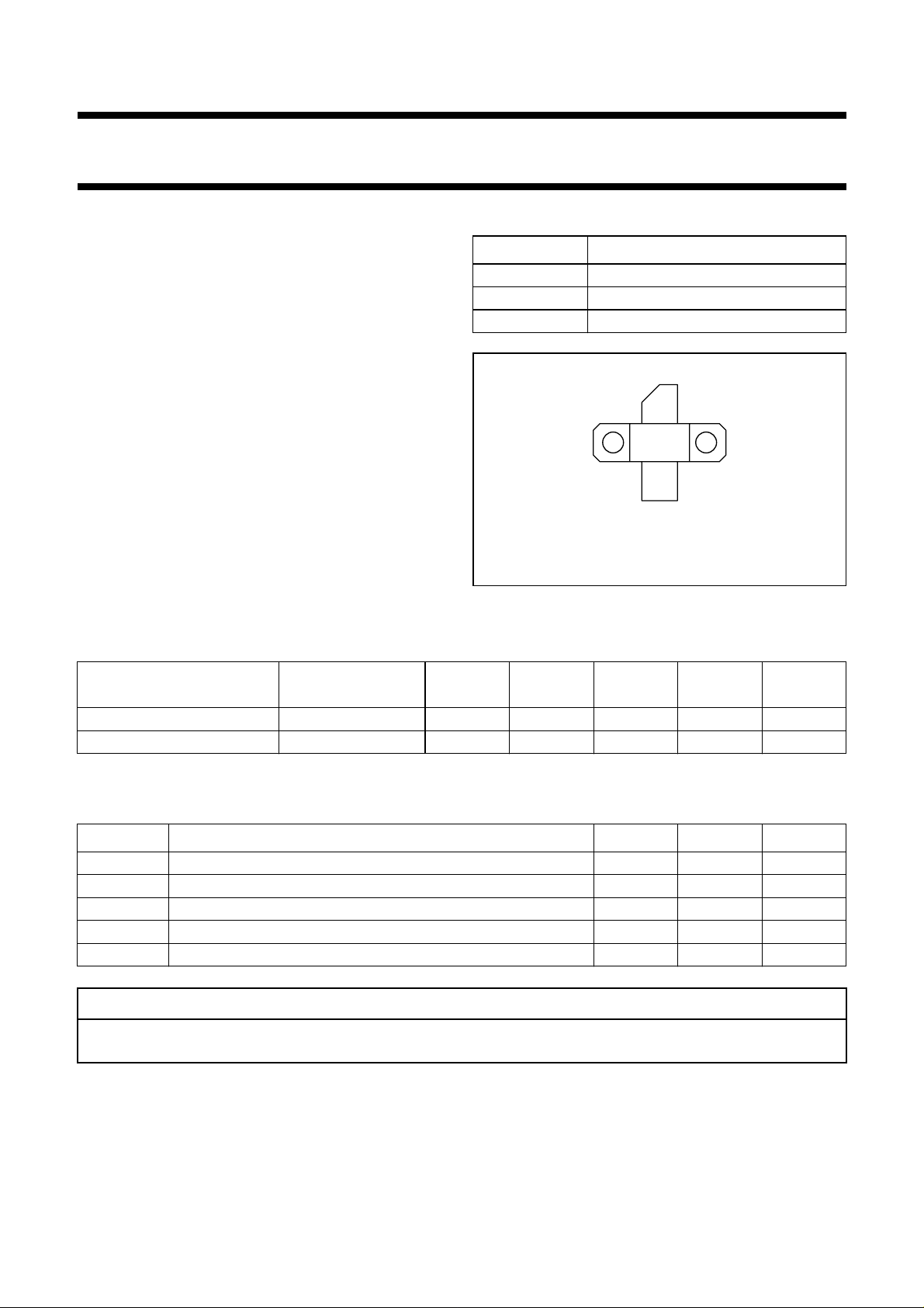
PINNING - SOT467C
PIN DESCRIPTION
1 drain
2 gate
3 source, connected to flange
common mode inductance
• Designed for broadband operation (HF to 1 GHz).
APPLICATIONS
• Communication transmitter applications in the UHF
frequency range.
DESCRIPTION
Silicon N-channel enhancement mode lateral D-MOS
transistor encapsulated in a 2-lead flange package
(SOT467C) with a ceramic cap. The common source is
connected to the mounting flange.
QUICK REFERENCE DATA
RF performance at Th=25°C in the common source broadband test circuit.
1
3
2
Top view
MBK584
Fig.1 Simplified outline.
MODE OF OPERATION
CW, class-AB (2-tone) f
f
(MHz)
= 960; f2= 960.1 26 45 (PEP) >14 >35 ≤−26
1
V
(V)
DS
P
(W)
L
G
(dB)
p
η
D
(%)
d
(dBc)
CW, class-AB (1-tone) 960 26 45 >14 >46 −
LIMITING VALUES
In accordance with the Absolute Maximum Rating System (IEC 60134).
SYMBOL PARAMETER MIN. MAX. UNIT
V
DS
V
GS
I
D
T
stg
T
j
drain-source voltage − 65 V
gate-source voltage −±20 V
drain current (DC) − 4.5 A
storage temperature −65 +150 °C
junction temperature − 200 °C
CAUTION
This product is supplied in anti-static packing to prevent damage caused by electrostatic discharge during transport
and handling. For further information, refer to Philips specs.: SNW-EQ-608, SNW-FQ-302A and SNW-FQ-302B.
im
2000 Dec 20 2
Page 3

Philips Semiconductors Product specification
UHF power LDMOS transistor BLF1046
THERMAL CHARACTERISTICS
SYMBOL PARAMETER CONDITIONS VALUE UNIT
R
th j-h
thermal resistance from junction to
heatsink
Note
1. Determined under specified RF operating conditions, based on maximum peak junction temperature.
CHARACTERISTICS
T
=25°C unless otherwise specified.
j
SYMBOL PARAMETER CONDITIONS MIN. TYP. MAX. UNIT
V
(BR)DSS
V
GSth
I
DSS
I
DSX
I
GSS
g
fs
R
DSon
C
is
C
os
C
rs
drain-source breakdown voltage VGS= 0; ID= 0.7 mA 65 −−V
gate-source threshold voltage VDS= 10 V; ID=70mA 4 − 5V
drain-source leakage current VGS= 0; VDS=26V −−1µA
drain cut-off current VGS=V
gate leakage current VGS= ±20 V; VDS=0 −−125 nA
forward transconductance VDS= 10 V; ID= 3.5 A − 2 − S
drain-source on-state resistance VGS=V
input capacitance VGS= 0; VDS= 26 V; f = 1 MHz − 46 − pF
output capacitance VGS= 0; VDS= 26 V; f = 1 MHz − 37 − pF
feedback capacitance VGS= 0; VDS= 26 V; f = 1 MHz − 1.5 − pF
Th=25°C; P
GSth
GSth
= 97 W; note 1 1.87 K/W
dis
+9V; VDS= 10 V 12.5 −−A
+9V; ID= 3.5 A − 300 − mΩ
APPLICATION INFORMATION
RF performance in the common source class-AB broadband test circuit. T
=25°C; R
h
= 1.87 K/W,
th j-h
unless otherwise specified.
MODE OF OPERATION
CW, class-AB (2-tone) f
f
(MHz)
= 960; f2= 960.1 26 300 45 (PEP) >14 >35 ≤−26
1
V
(V)
DS
I
DQ
(mA)
P
(W)
L
G
p
(dB)
η
(%)
D
d
im
(dBc)
CW, class-AB (1-tone) 960 26 300 45 >14 >46 −
Ruggedness in class-AB operation
The BLF1046is capable of withstanding a load mismatch corresponding to VSWR = 10 : 1 through all phases under the
following conditions: V
= 26 V; f = 960 MHz at rated load power.
DS
Tuning Procedure
For high gain and efficiency:
In CW mode (PD= 1 W; f = 960 MHz) tune C2 and C16 (see Figs. 13 and 14) until IRL < −15 dB, then adjust C6 and C8
for high gain until Gp> 14 dB at PL=50W.
For linear mode:
Tune for high gain and efficiency mode, then apply two tone signal (f1= 960 MHz; f2= 960.1 MHz) at PL= 45 W (PEP)
and tune first C2 and then C6 and C8 for lowest d3 (below −28 dBc).
2000 Dec 20 3
Page 4
Philips Semiconductors Product specification
UHF power LDMOS transistor BLF1046
20
handbook, halfpage
G
p
(dB)
15
10
5
0
020
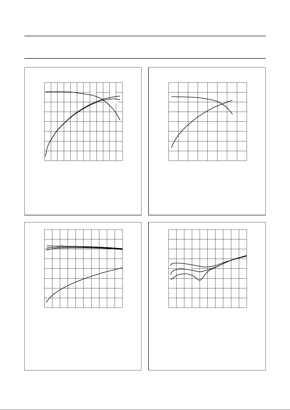
VDS= 26 V; IDQ= 330 mA; Th≤ 25 °C; f = 960 MHz;
tuned for high efficiency; see tuning procedure.
G
p
40
MLD455
η
D
PAE
P
(W)
L
Fig.2 Powergainanddrainefficiencyasfunctions
of load power; typical values.
60
P
MLD456
(W)
L
80
η
D
(%)
60
40
20
0
80
η
D
(%)
60
40
20
0
60
20
handbook, halfpage
G
p
(dB)
15
10
5
0
020
VDS= 26 V; IDQ= 330 mA; Th≤ 25 °C; f = 960 MHz;
tuned for high linearity; see tuning procedure
G
p
η
D
40 80
Fig.3 Powergainanddrainefficiencyasfunctions
of load power; typical values.
P
(PEP) (W)
L
MLD457
20
handbook, halfpage
G
p
(dB)
15
10
VDS= 26 V; Th≤ 25 °C; f1= 960 MHz; f2= 960.1 MHz;
tuned for high linearity; see tuning procedure.
(1) I
DQ
(2) IDQ= 300 mA.
(3) IDQ= 400 mA.
(3) (2)
(1)
η
5
0
010
= 240 mA.
D
20 30 40
Fig.4 Powergainanddrainefficiencyasfunctions
of peak envelope power; typical values.
P
(PEP) (W)
L
MLD458
50
80
η
D
(%)
60
40
20
0
50
handbook, halfpage
0
d
3
(dB)
−20
(1)
−40
−60
−80
010
VDS= 26 V; Th≤ 25 °C; f1= 960 MHz; f2= 960.1 MHz;
tuned for high linearity; see tuning procedure.
= 240 mA.
(1) I
DQ
(2) IDQ= 300 mA.
(3) IDQ= 400 mA.
(2)
(3)
20 30 40
Fig.5 Third order intermodulation distortion as a
function of peak envelope load power;
typical values.
2000 Dec 20 4
Page 5
Philips Semiconductors Product specification
UHF power LDMOS transistor BLF1046
P
(PEP) (W)
L
MLD459
handbook, halfpage
0
d
5
(dBc)
−20
−40
−60
−80
010
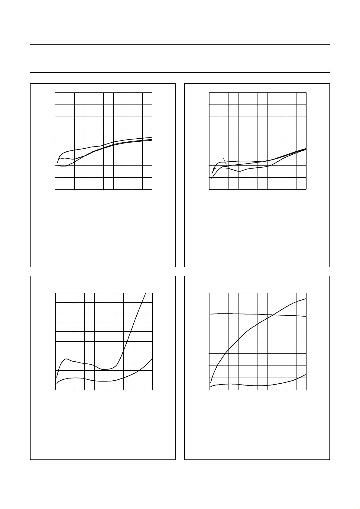
VDS= 26 V; Th≤ 25 °C; f1= 960 MHz; f2= 960.1 MHz;
tuned for high linearity; see tuning procedure.
= 240 mA.
(1) I
DQ
(2) IDQ= 300 mA.
(3) IDQ= 400 mA.
(1)
(3)
(2)
20 30 40
Fig.6 Fifth order intermodulation distortion as a
function of peak envelope load power;
typical values.
P
(PEP) (W)
L
MLD460
50
handbook, halfpage
50
0
d
7
(dBc)
−20
−40
(1)
(3)
−60
(2)
−80
010
VDS= 26 V; Th≤ 25 °C; f1= 960 MHz; f2= 960.1 MHz;
tuned for high linearity; see tuning procedure.
= 240 mA.
(1) I
DQ
(2) IDQ= 300 mA.
(3) IDQ= 400 mA.
20 30 40
Fig.7 Seventh order intermodulation distortion as
a function of peak envelope load power;
typical values.
10
handbook, halfpage
EVM
(%)
8
6
4
2
0
020
VDS= 26 V; IDQ= 300 mA; Th≤ 25 °C; f = 960 MHz;
tuned for high linearity; see tuning procedure.
4 8 12 16
peak
rms
Fig.8 Error vector magnitude (EVM) / EDGE
8PSK as a functions of load power; typical
values.
MLD461
PL (W)
20
handbook, halfpage
G
p
(dB)
15
10
5
EVM
(%)
0
04
VDS= 26 V; IDQ= 300 mA; Th≤ 25 °C; f = 960 MHz;
tuned for high linearity; see tuning procedure.
G
p
η
EVM
81216
MLD462
P
(W)
L
Fig.9 EDGE 8PSK EVM, gain and efficiency as
functions of load power; typical values.
40
η
(%)
30
20
10
0
20
2000 Dec 20 5
Page 6
Philips Semiconductors Product specification
UHF power LDMOS transistor BLF1046
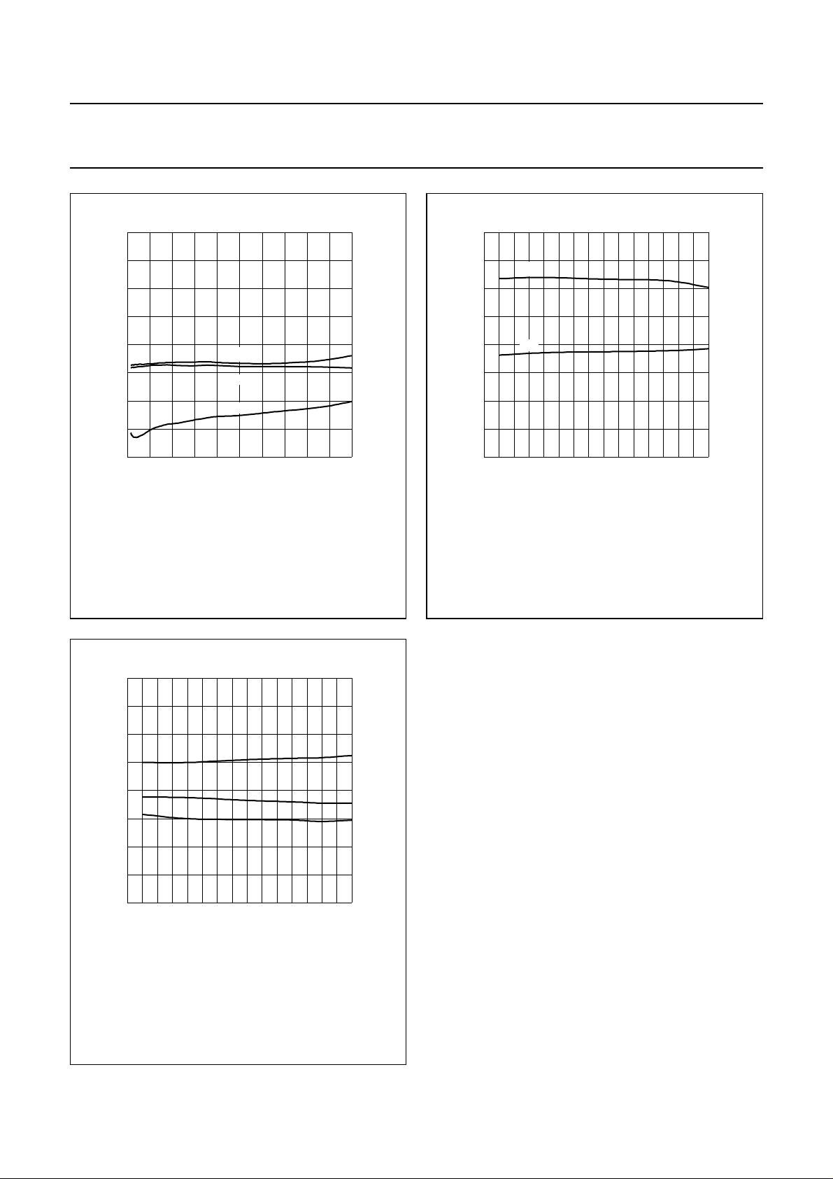
handbook, halfpage
0
ACPR
(dBc)
−20
−40
−60
−80
04
VDS= 26 V; IDQ= 300 mA; Th≤ 25 °C; f = 960 MHz;
tuned for high linearity; see tuning procedure.
Measured EDGE channel bandwidth 270 kHz and adjacent
channels bandwidth 30 kHz.
200 KHz
250 KHz
400 KHz
81216
MLD463
P
(W)
L
Fig.10 EDGE 8PSK adjacent channel power as a
function of load power; typical values.
MLD464
1000
80
(%)
60
40
20
0
η
D
20
handbook, halfpage
G
p
(dB)
15
10
5
0
20
850 900
VDS= 28 V; IDQ= 300 mA; PL= 45 W (PEP); Th≤ 25 °C;
tuned for high linearity; see tuning procedure
Measured in broadband test circuit; see Figs. 15 and 16.
G
p
η
D
950
f (MHz)
Fig.11 Power gain and drainefficiencyasfunctions
of frequency; typical values.
handbook, halfpage
0
d
im
(dBc)
−20
d
3
d
−40
−60
−80
850 900
VDS= 28 V; IDQ= 300 mA; PL= 45 W (PEP); Th≤ 25 °C;
tuned for high linearity; see tuning procedure
Measured in broadband test circuit; see Figs. 15 and 16.
5
d
7
950
MLD465
f (MHz)
Fig.12 Intermodulation distortion as a function of
frequency; typical values.
1000
2000 Dec 20 6
Page 7
Philips Semiconductors Product specification
UHF power LDMOS transistor BLF1046
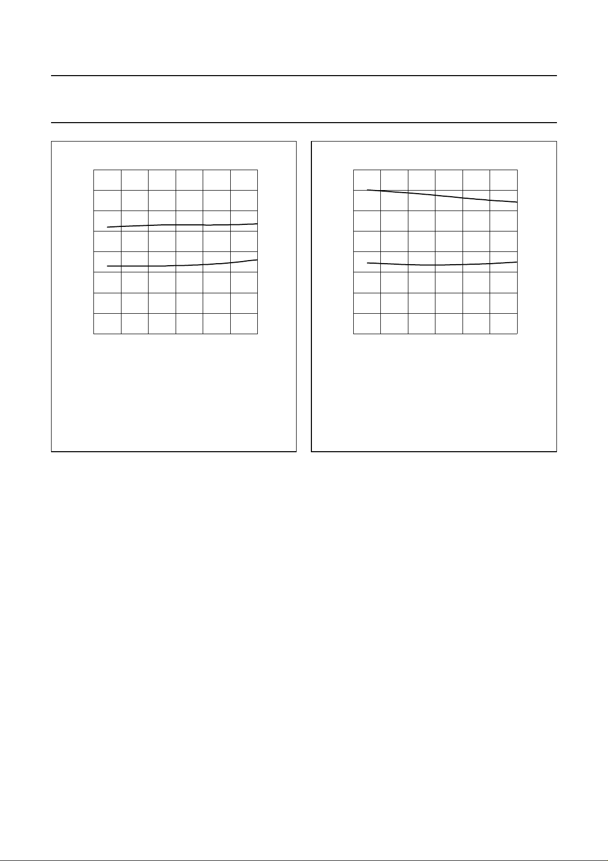
handbook, halfpage
4
Z
i
(Ω)
2
0
−2
−4
840 880
VDS= 26 V; IDQ= 300 mA; PL= 45 W; Th≤ 25 °C;
tuned for high linearity; see tuning procedure.
r
i
x
i
920 960
MLD468
f (MHz)
Fig.13 Optimal source impedance as a function of
frequency (series components);
typical values.
handbook, halfpage
4
Z
L
(Ω)
2
0
−2
−4
840 880
VDS= 26 V; IDQ= 300 mA; PL= 45 W; Th≤ 25 °C;
tuned for high linearity; see tuning procedure.
R
L
X
L
920 960
MLD469
f (MHz)
Fig.14 Optimal load impedance as a function of
frequency (series components);
typical values.
2000 Dec 20 7
Page 8
Philips Semiconductors Product specification
UHF power LDMOS transistor BLF1046
handbook, full pagewidth
C13
C10
C9
50 Ω
input
C16
L3
R5
C15C14
C11
L2
C5
L6
L8
L7
C6
C1
C2
R1
R2
F1
R3
R4
C3
L1
L4
L5
C4
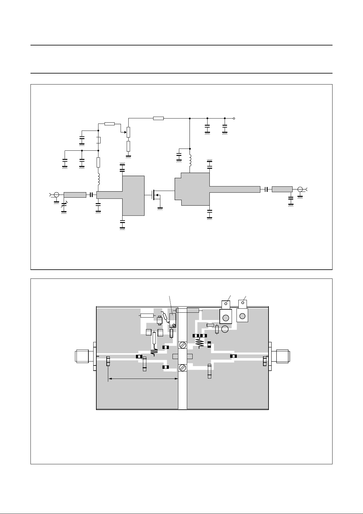
Fig.15 Class-AB broadband test circuit at f = 800 to 1000 MHz.
(26 V)
V
DS
L9
C7
C8
50 Ω
output
MLD466
+ 26 V
C7
ground
C8
MLD467
C13
C1
IDQ adjustment
F1
C9
C10
R4
L1
C2
R1
R3
C3
C4
R2
R5
C11
L2
TRGD
C12
C5
C14
C6
C15
handbook, full pagewidth
input
C16
39 mm
Dimensions in mm.
The components are situated on one side of the copper-clad printed-circuit board with Teflon dielectric (εr= 2.2), thickness 0.79 mm.
The other side is unetched and serves as a ground plane.
Fig.16 Component layout for 800 to 1000 MHz class-AB broadband test circuit.
output
2000 Dec 20 8
Page 9

Philips Semiconductors Product specification
UHF power LDMOS transistor BLF1046
List of components (see Figs 15 and 16)
COMPONENT DESCRIPTION VALUE DIMENSIONS CATALOGUE NO.
C1, C7 multilayer ceramic chip capacitor; note 1 33 pF
C2, C6 Tekelec variable capacitor 0.8 to 8.2 pF
C3, C4 multilayer ceramic chip capacitor; note 1 13 pF
C5 multilayer ceramic chip capacitor; note 1 7.5 pF
C8, C16 Tekelec variable capacitor 0.5 to 4.6 pF
C9, C11 multilayer ceramic chip capacitor; note 1 33 pF
C10, C12 multilayer ceramic chip capacitor; note 1 150 pF
C13, C14 multilayer ceramic chip capacitor 33 nF
C15 electrolytic capacitor 47 µF; 63 V
F1 Ferroxcube chip-bead 8DS3/3/8/9-4S2 4330 030 36301
L1 5 turns enamelled 0.6 mm copper wire int. dia.=4mm;
length = 5 mm
L2 2 turns enamelled 0.6 mm copper wire int. dia.=4mm;
length = 1.6 mm
L3 stripline; note 2 50 Ω 16 × 2.36 mm
L4 stripline; note 2 42.5 Ω 16× 3.1 mm
L5 stripline; note 2 14.3 Ω 6× 12 mm
L6 stripline; note 2 20.2 Ω 3× 8mm
L7 stripline; note 2 14.3 Ω 14× 12 mm
L8 stripline; note 2 40 Ω 17 × 3.4 mm
L9 stripline; note 2 50 Ω 7 × 2.36 mm
R1, R5 metal film resistor 10 kΩ, 0.6 W
R2 variable resistor 10 kΩ
R3 metal film resistor 1kΩ, 0.6 W
R4 metal film resistor 10Ω, 0.6 W
Notes
1. American Technical Ceramics type 100B or capacitor of same quality.
2. The striplines are on a double copper-clad printed-circuit board with Teflon dielectric (εr = 2.2); thickness 0.79 mm.
2000 Dec 20 9
Page 10
Philips Semiconductors Product specification
UHF power LDMOS transistor BLF1046
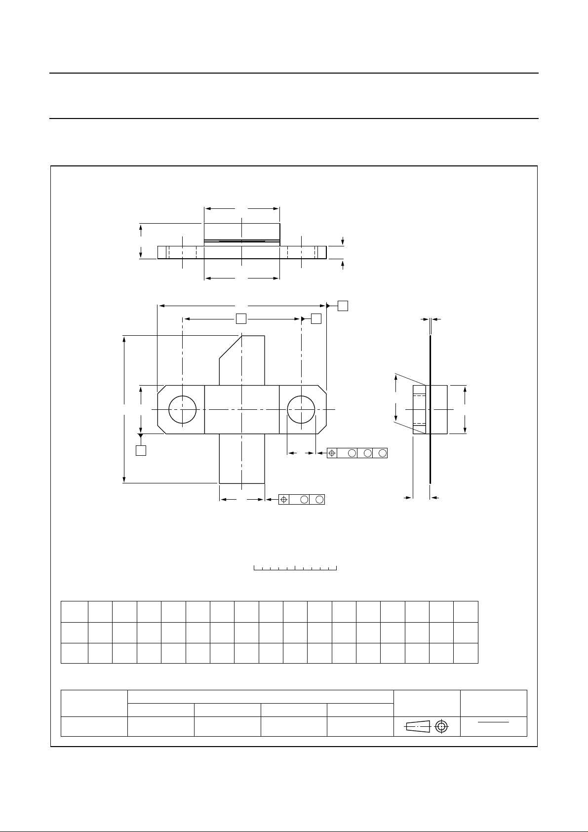
PACKAGE OUTLINE
Flanged LDMOST ceramic package; 2 mounting holes; 2 leads
D
A
3
D
1
F
SOT467C
U
q
1
B
C
c
1
E
H
U
2
A
p
w
M M M
AB
1
1
E
2
w
M M
scale
C
2
b
0 5 10 mm
Q
DIMENSIONS (millimetre dimensions are derived from the original inch dimensions)
UNIT
mm
inch
OUTLINE
VERSION
SOT467C
A
4.67
3.94
0.184
0.155
b
5.59
5.33
0.220
0.210
cD
0.15
0.10
0.006
0.004
IEC JEDEC EIAJ
9.25
9.04
0.364
0.356
D
1
9.27
9.02
0.365
0.355
E
5.92
5.77
0.233
0.227
0.235
0.225
REFERENCES
FH p q
E
1
5.97
1.65
1.40
0.065
0.055
18.54
17.02
0.73
0.67
5.72
2000 Dec 20 10
3.43
3.18
0.135
0.125
Q
2.21
1.96
0.087
0.077
14.27
0.562
U
20.45
20.19
0.805
0.795
1
U
w
2
5.97
0.25
5.72
0.235
0.010 0.020
0.225
EUROPEAN
PROJECTION
w
1
2
0.51
ISSUE DATE
99-12-06
99-12-28
Page 11

Philips Semiconductors Product specification
UHF power LDMOS transistor BLF1046
DATA SHEET STATUS
DATA SHEET STATUS
Objective specification Development This data sheet contains the design target or goal specifications for
Preliminary specification Qualification Thisdata sheet contains preliminary data, and supplementary data will be
Product specification Production This data sheet contains final specifications. Philips Semiconductors
Note
1. Please consult the most recently issued data sheet before initiating or completing a design.
DEFINITIONS
Short-form specification The data in a short-form
specification is extracted from a full data sheet with the
same type number and title. For detailed information see
the relevant data sheet or data handbook.
Limiting values definition Limiting values given are in
accordance with the Absolute Maximum Rating System
(IEC 60134). Stress above one or more of the limiting
values may cause permanent damage to the device.
These are stress ratings only and operation of the device
attheseoratany other conditions above those given in the
Characteristics sections of the specification is not implied.
Exposure to limiting values for extended periods may
affect device reliability.
Application information Applications that are
described herein for any of these products are for
illustrative purposes only. Philips Semiconductors make
norepresentationorwarrantythatsuchapplicationswillbe
suitable for the specified use without further testing or
modification.
PRODUCT
STATUS
DEFINITIONS
product development. Specification may change in any manner without
notice.
published at a later date. Philips Semiconductors reserves the right to
make changes at any time without notice in order to improve design and
supply the best possible product.
reserves the right to make changes at any time without notice in order to
improve design and supply the best possible product.
DISCLAIMERS
Life support applications These products are not
designed for use in life support appliances, devices, or
systems where malfunction of these products can
reasonably be expected to result in personal injury. Philips
Semiconductorscustomersusingorsellingtheseproducts
for use in such applications do so at their own risk and
agree to fully indemnify Philips Semiconductors for any
damages resulting from such application.
Right to make changes Philips Semiconductors
reserves the right to make changes, without notice, in the
products, including circuits, standard cells, and/or
software, described or contained herein in order to
improve design and/or performance. Philips
Semiconductors assumes no responsibility or liability for
theuseofanyoftheseproducts,conveysnolicenceortitle
under any patent, copyright, or mask work right to these
products,andmakes no representations or warranties that
these products are free from patent, copyright, or mask
work right infringement, unless otherwise specified
(1)
2000 Dec 20 11
Page 12

Philips Semiconductors – a w orldwide compan y
Argentina: see South America
Australia: 3 Figtree Drive, HOMEBUSH, NSW 2140,
Tel. +61 2 9704 8141, Fax. +61 2 9704 8139
Austria: Computerstr. 6, A-1101 WIEN, P.O. Box 213,
Tel. +43 1 60 101 1248, Fax. +43 1 60 101 1210
Belarus: Hotel Minsk Business Center, Bld. 3, r. 1211, Volodarski Str. 6,
220050 MINSK, Tel. +375 172 20 0733, Fax. +375 172 20 0773
Belgium: see The Netherlands
Brazil: see South America
Bulgaria: Philips Bulgaria Ltd., Energoproject, 15th floor,
51 James Bourchier Blvd., 1407 SOFIA,
Tel. +359 2 68 9211, Fax. +359 2 68 9102
Canada: PHILIPS SEMICONDUCTORS/COMPONENTS,
Tel. +1 800 234 7381, Fax. +1 800 943 0087
China/Hong Kong: 501 Hong Kong Industrial Technology Centre,
72 Tat Chee Avenue, Kowloon Tong, HONG KONG,
Tel. +852 2319 7888, Fax. +852 2319 7700
Colombia: see South America
Czech Republic: see Austria
Denmark: Sydhavnsgade 23, 1780 COPENHAGEN V,
Tel. +45 33 29 3333, Fax. +45 33 29 3905
Finland: Sinikalliontie 3, FIN-02630 ESPOO,
Tel. +358 9 615 800, Fax. +358 9 6158 0920
France: 51 Rue Carnot, BP317, 92156 SURESNES Cedex,
Tel. +33 1 4099 6161, Fax. +33 1 4099 6427
Germany: Hammerbrookstraße 69, D-20097 HAMBURG,
Tel. +49 40 2353 60, Fax. +49 40 2353 6300
Hungary: see Austria
India: Philips INDIA Ltd, Band Box Building, 2nd floor,
254-D, Dr. Annie Besant Road, Worli, MUMBAI 400 025,
Tel. +91 22 493 8541, Fax. +91 22 493 0966
Indonesia: PTPhilips DevelopmentCorporation, Semiconductors Division,
Gedung Philips, Jl. Buncit Raya Kav.99-100, JAKARTA 12510,
Tel. +62 21 794 0040 ext. 2501, Fax. +62 21 794 0080
Ireland: Newstead, Clonskeagh, DUBLIN 14,
Tel. +353 1 7640 000, Fax. +353 1 7640 200
Israel: RAPAC Electronics, 7 Kehilat Saloniki St, PO Box 18053,
TEL AVIV 61180, Tel. +972 3 645 0444, Fax. +972 3 649 1007
Italy: PHILIPS SEMICONDUCTORS,ViaCasati, 23 - 20052 MONZA (MI),
Tel. +39 039 203 6838, Fax +39 039 203 6800
Japan: Philips Bldg 13-37, Kohnan 2-chome, Minato-ku,
TOKYO 108-8507, Tel. +81 3 3740 5130, Fax. +81 3 3740 5057
Korea: Philips House, 260-199 Itaewon-dong, Yongsan-ku, SEOUL,
Tel. +82 2 709 1412, Fax. +82 2 709 1415
Malaysia: No. 76 Jalan Universiti, 46200 PETALING JAYA, SELANGOR,
Tel. +60 3 750 5214, Fax. +60 3 757 4880
Mexico: 5900 Gateway East, Suite 200, EL PASO, TEXAS 79905,
Tel. +9-5 800 234 7381, Fax +9-5 800 943 0087
Middle East: see Italy
Netherlands: Postbus 90050, 5600 PB EINDHOVEN, Bldg. VB,
Tel. +31 40 27 82785, Fax. +31 40 27 88399
New Zealand: 2 Wagener Place, C.P.O. Box 1041, AUCKLAND,
Tel. +64 9 849 4160, Fax. +64 9 849 7811
Norway: Box 1, Manglerud 0612, OSLO,
Tel. +47 22 74 8000, Fax. +47 22 74 8341
Pakistan: see Singapore
Philippines: Philips Semiconductors Philippines Inc.,
106 Valero St. Salcedo Village, P.O. Box 2108 MCC, MAKATI,
Metro MANILA, Tel. +63 2 816 6380, Fax. +63 2 817 3474
Poland: Al.Jerozolimskie 195 B, 02-222 WARSAW,
Tel. +48 22 5710 000, Fax. +48 22 5710 001
Portugal: see Spain
Romania: see Italy
Russia: Philips Russia, Ul. Usatcheva 35A, 119048 MOSCOW,
Tel. +7 095 755 6918, Fax. +7 095 755 6919
Singapore: Lorong 1, Toa Payoh, SINGAPORE 319762,
Tel. +65 350 2538, Fax. +65 251 6500
Slovakia: see Austria
Slovenia: see Italy
South Africa: S.A. PHILIPS Pty Ltd., 195-215 Main Road Martindale,
2092 JOHANNESBURG, P.O. Box 58088 Newville 2114,
Tel. +27 11 471 5401, Fax. +27 11 471 5398
South America: Al. Vicente Pinzon, 173, 6th floor,
04547-130 SÃO PAULO, SP, Brazil,
Tel. +55 11 821 2333, Fax. +55 11 821 2382
Spain: Balmes 22, 08007 BARCELONA,
Tel. +34 93 301 6312, Fax. +34 93 301 4107
Sweden: Kottbygatan 7, Akalla, S-16485 STOCKHOLM,
Tel. +46 8 5985 2000, Fax. +46 8 5985 2745
Switzerland: Allmendstrasse 140, CH-8027 ZÜRICH,
Tel. +41 1 488 2741 Fax. +41 1 488 3263
Taiwan: Philips Semiconductors, 5F, No. 96, Chien Kuo N. Rd., Sec. 1,
TAIPEI, Taiwan Tel. +886 2 2134 2451, Fax. +886 2 2134 2874
Thailand: PHILIPS ELECTRONICS (THAILAND) Ltd.,
60/14 MOO 11, Bangna Trad Road KM. 3, Bagna, BANGKOK 10260,
Tel. +66 2 361 7910, Fax. +66 2 398 3447
Turkey: Yukari Dudullu, Org. San. Blg., 2.Cad. Nr. 28 81260 Umraniye,
ISTANBUL, Tel. +90 216 522 1500, Fax. +90 216 522 1813
Ukraine: PHILIPS UKRAINE, 4 Patrice Lumumba str., Building B, Floor 7,
252042 KIEV, Tel. +380 44 264 2776, Fax. +380 44 268 0461
United Kingdom: Philips Semiconductors Ltd., 276 Bath Road, Hayes,
MIDDLESEX UB3 5BX, Tel. +44 208 730 5000, Fax. +44 208 754 8421
United States: 811 East Arques Avenue, SUNNYVALE, CA 94088-3409,
Tel. +1 800 234 7381, Fax. +1 800 943 0087
Uruguay: see South America
Vietnam: see Singapore
Yugoslavia: PHILIPS, Trg N. Pasica 5/v, 11000 BEOGRAD,
Tel. +381 11 3341 299, Fax.+381 11 3342 553
For all other countries apply to: Philips Semiconductors,
Marketing Communications, Building BE-p, P.O. Box 218, 5600 MD EINDHOVEN,
The Netherlands, Fax. +31 40 27 24825
© Philips Electronics N.V. SCA
All rights are reserved. Reproduction in whole or in part is prohibited without the prior written consent of the copyright owner.
The information presented in this document does not form part of any quotation or contract, is believed to be accurate and reliable and may be changed
without notice. No liability will be accepted by the publisher for any consequence of its use. Publication thereof does not convey nor imply any license
under patent- or other industrial or intellectual property rights.
2000
Internet: http://www.semiconductors.philips.com
70
Printed in The Netherlands 613524/07/pp12 Date of release: 2000 Dec 20 Document order number: 9397 750 07658
 Loading...