

Page 1

BFG520; BFG520/X; BFG520/XR
NPN 9 GHz wideband transistor
Rev. 04 — 23 November 2007 Product data sheet
IMPORTANT NOTICE
Dear customer,
As from October 1st, 2006 Philips Semiconductors has a new trade name
- NXP Semiconductors, which will be used in future data sheets together with new contact
details.
In data sheets where the previous Philips references remain, please use the new links as
shown below.
http://www.philips.semiconductors.com use http://www.nxp.com
http://www.semiconductors.philips.com use http://www.nxp.com (Internet)
[email protected] use [email protected]
(email)
The copyright notice at the bottom of each page (or elsewhere in the document,
depending on the version)
- © Koninklijke Philips Electronics N.V. (year). All rights reserved is replaced with:
- © NXP B.V. (year). All rights reserved. If you have any questions related to the data sheet, please contact our nearest sales
office via e-mail or phone (details via [email protected]). Thank you for your
cooperation and understanding,
NXP Semiconductors
Page 2
NXP Semiconductors Product specification
Rev. 04 - 23 November 2007
2 of 14
NPN 9 GHz wideband transistor BFG520; BFG520/X; BFG520/XR
FEATURES
• High power gain
• Low noise figure
• High transition frequency
• Gold metallization ensures
excellent reliability.
DESCRIPTION
NPN silicon planar epitaxial
transistors, intended for applications
in the RF frontend in the GHz range,
such as analog and digital cellular
telephones, cordless telephones
(CT1, CT2, DECT, etc.), radar
detectors, pagers and satellite TV
tuners (SATV) and repeater
amplifiers in fibre-optic systems.
The transistors are encapsulated in
4-pin, dual-emitter plastic SOT143
and SOT143R envelopes.
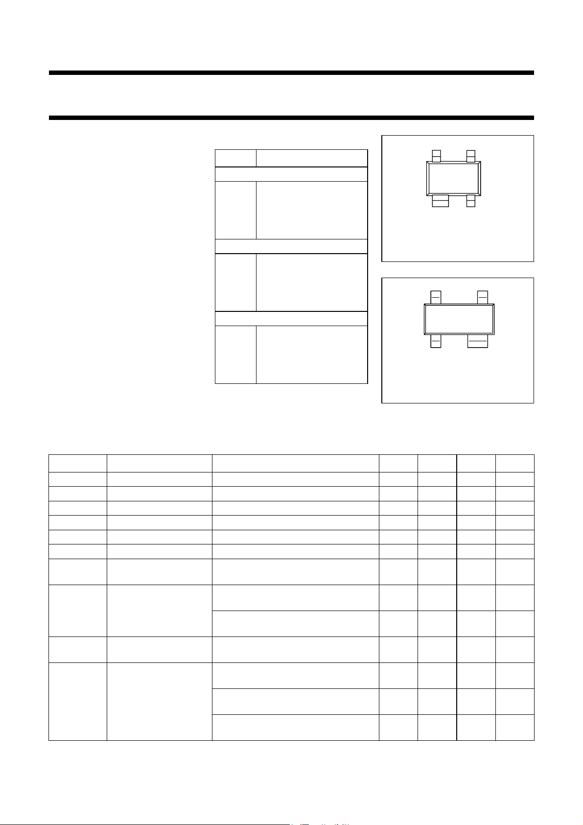
PINNING
PIN DESCRIPTION
BFG520 (Fig.1) Code: %MF
1 collector
2 base
3 emitter
4 emitter
BFG520/X (Fig.1) Code: %ML
1 collector
2 emitter
3 base
4 emitter
BFG520/XR (Fig.2) Code: %MP
1 collector
2 emitter
3 base
4 emitter
page
12
Top view
Fig.1 SOT143B.
handbook, 2 columns
Top view
Fig.2 SOT143R.
34
MSB014
43
12
MSB035
QUICK REFERENCE DATA
SYMBOL PARAMETER CONDITIONS MIN. TYP. MAX. UNIT
V
CBO
V
CEO
I
c
P
tot
h
FE
C
re
f
T
G
UM
2
S
21
F noise figure Γ
collector-base voltage open emitter −−20 V
collector-emitter voltage open base −−15 V
DC collector current −−70 mA
total power dissipation up to Ts=88°C; note 1 −−300 mW
DC current gain IC= 20 mA; VCE= 6 V; Tj=25°C 60 120 250
feedback capacitance IC = 0; VCB = 6 V; f = 1 MHz − 0.3 − pF
transition frequency IC= 20 mA; VCE= 6 V; f = 1 GHz;
=25°C
T
amb
maximum unilateral
power gain
IC= 20 mA; VCE= 6 V; f = 900 MHz;
T
=25°C
amb
I
= 20 mA; VCE= 6 V; f = 2 GHz;
C
T
=25°C
amb
insertion power gain IC= 20 mA; VCE= 6 V; f = 900 MHz;
T
=25°C
amb
= Γ
s
f = 900 MHz; T
Γ
s
f = 900 MHz; T
Γ
s
f = 2 GHz; T
; Ic= 5 mA; VCE=6V;
opt
=25°C
amb
= Γ
; IC= 20 mA; VCE=6 V;
opt
=25°C
amb
= Γ
; IC= 5 mA; VCE= 8 V;
opt
=25°C
amb
− 9 − GHz
− 19 − dB
− 13 − dB
17 18 − dB
− 1.1 1.6 dB
− 1.6 2.1 dB
− 1.9 − dB
Page 3
NXP Semiconductors Product specification
Rev. 04 - 23 November 2007
3 of 14
NPN 9 GHz wideband transistor BFG520; BFG520/X; BFG520/XR
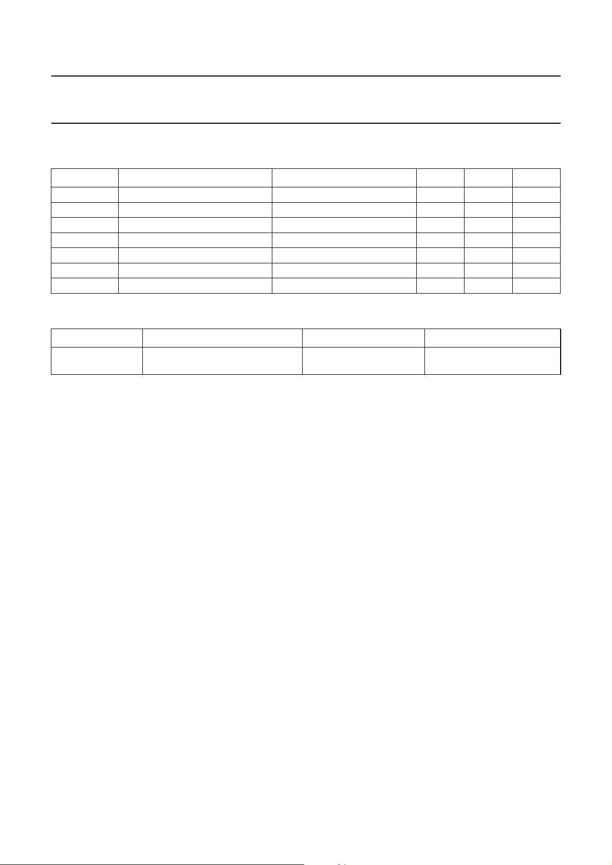
LIMITING VALUES
In accordance with the Absolute Maximum System (IEC 134).
SYMBOL PARAMETER CONDITIONS MIN. MAX. UNIT
V
CBO
V
CEO
V
EBO
I
C
P
tot
T
stg
T
j
THERMAL RESISTANCE
SYMBOL PARAMETER CONDITIONS THERMAL RESISTANCE
R
th j-s
collector-base voltage open emitter − 20 V
collector-emitter voltage open base − 15 V
emitter-base voltage open collector − 2.5 V
DC collector current − 70 mA
total power dissipation up to Ts = 88 °C; note 1 − 300 mW
storage temperature −65 150 °C
junction temperature − 175 °C
thermal resistance from junction to
up to Ts=88°C; note 1 290 K/W
soldering point
Note
1. T
is the temperature at the soldering point of the collector tab.
s
Page 4
NXP Semiconductors Product specification
Rev. 04 - 23 November 2007
4 of 14
NPN 9 GHz wideband transistor BFG520; BFG520/X; BFG520/XR
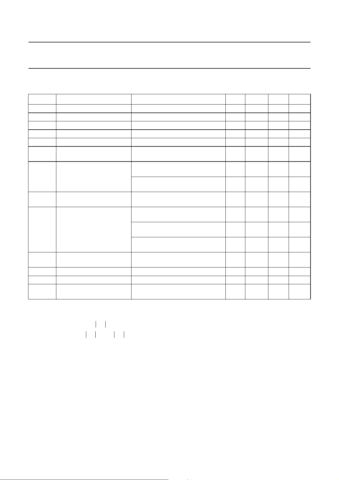
CHARACTERISTICS
T
= 25 °C unless otherwise specified.
j
SYMBOL PARAMETER CONDITIONS MIN. TYP. MAX. UNIT
I
CBO
h
FE
C
e
C
c
C
re
f
T
G
UM
S
21
F noise figure Γ
P
L1
ITO third order intercept point note 2 − 26 − dBm
V
o
d
2
collector cut-off current IE = 0; VCB = 6 V −− 50 nA
DC current gain IC= 20 mA; VCE= 6 V 60 120 250
emitter capacitance IC=ic=0;VEB= 0.5 V; f = 1 MHz − 1 − pF
collector capacitance IE=ie=0;VCB= 6 V; f = 1 MHz − 0.6 − pF
feedback capacitance IC=0;VCB= 6 V; f = 1 MHz − 0.3 − pF
transition frequency IC = 20 mA; VCE = 6 V; f = 1 GHz;
T
=25°C
amb
maximum unilateral
power gain (note 1)
2
insertion power gain IC= 20 mA; VCE= 6 V; f = 900 MHz;
output power at 1 dB gain
compression
IC= 20 mA; VCE= 6 V; f = 900 MHz;
T
= 25 °C
amb
I
= 20 mA; VCE= 6 V; f = 2 GHz;
C
T
= 25 °C
amb
T
= 25 °C
amb
= Γ
s
f = 900 MHz; T
= Γ
Γ
s
f = 900 MHz; T
Γ
= Γ
s
f = 2 GHz; T
= 5 mA; VCE=6V;
opt;IC
=25°C
amb
; IC= 20 mA; VCE=6 V;
opt
=25°C
amb
= 5 mA; VCE=6 V;
opt;IC
=25°C
amb
IC= 20 mA; VCE= 6 V; RL=50Ω;
f = 900 MHz; T
amb
=25°C
− 9 − GHz
− 19 − dB
− 13 − dB
17 18 − dB
− 1.1 1.6 dB
− 1.6 2.1 dB
− 1.9 − dB
− 17 − dBm
output voltage note 3 − 275 − mV
second order intermodulation
distortion
IC= 20 mA; VCE= 6 V; Vo= 75 mV;
T
amb
=25°C; f
(p+q)
= 810 MHz
−−50 − dB
Notes
1. G
2. I
is the maximum unilateral power gain, assuming S12is zero and
UM
G
UM
= 20 mA; VCE= 6 V; RL=50Ω; f = 900 MHz; T
C
--------------------------------------------------------------
10 log
1S
–
2
S
21
2
1S
–
11
22
dB.=
2
fp= 900 MHz; fq= 902 MHz;
measured at f
= 898 MHz and f
(2p−q)
(2q−p)
= 904 MHz.
3. dim= −60 dB (DIN 45004B);
Vp=Vo;Vq=Vo−6 dB; Vr=Vo−6 dB;
fp= 795.25 MHz; fq= 803.25 MHz; fr= 805.25 MHz;
measured at f
= 793.25 MHz
(p+q−r)
amb
=25°C;
Page 5
NXP Semiconductors Product specification
Rev. 04 - 23 November 2007
5 of 14
NPN 9 GHz wideband transistor BFG520; BFG520/X; BFG520/XR
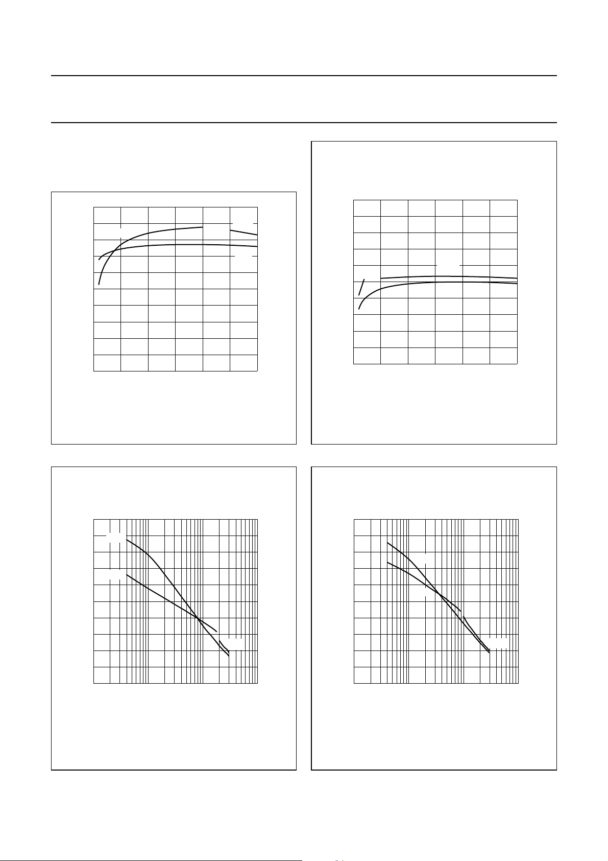
400
handbook, halfpage
P
tot
(mW)
300
200
100
0
0 50 100 200
150
Ts (oC)
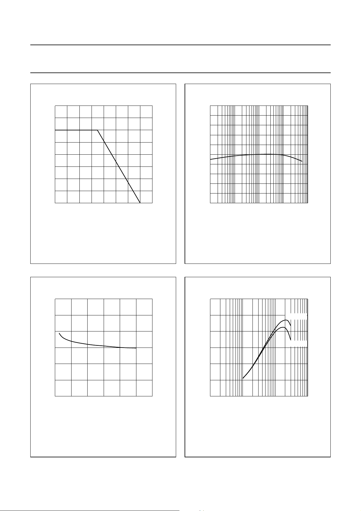
Fig.3 Power derating curve.
MRA670-1
250
handbook, halfpage
h
FE
200
150
100
50
0
−2
10
VCE= 6 V; Tj=25°C.
−1
10
11010
MRA671
IC (mA)
Fig.4 DC current gain as a function of collector
current.
2
0.6
handbook, halfpage
C
re
(pF)
0.4
0.2
0
0
IC= 0; f = 1 MHz.
4812
VCB (V)
Fig.5 Feedback capacitance as a function of
collector-base voltage.
MRA672
12
handbook, halfpage
f
T
(GHz)
8
4
0
−1
10
f = 1 GHz; T
amb
11010
=25°C.
V
V
IC (mA)
Fig.6 Transition frequency as a function of
collector current.
CE
CE
MRA673
= 6 V
= 3 V
2
Page 6
NXP Semiconductors Product specification
Rev. 04 - 23 November 2007
6 of 14
NPN 9 GHz wideband transistor BFG520; BFG520/X; BFG520/XR
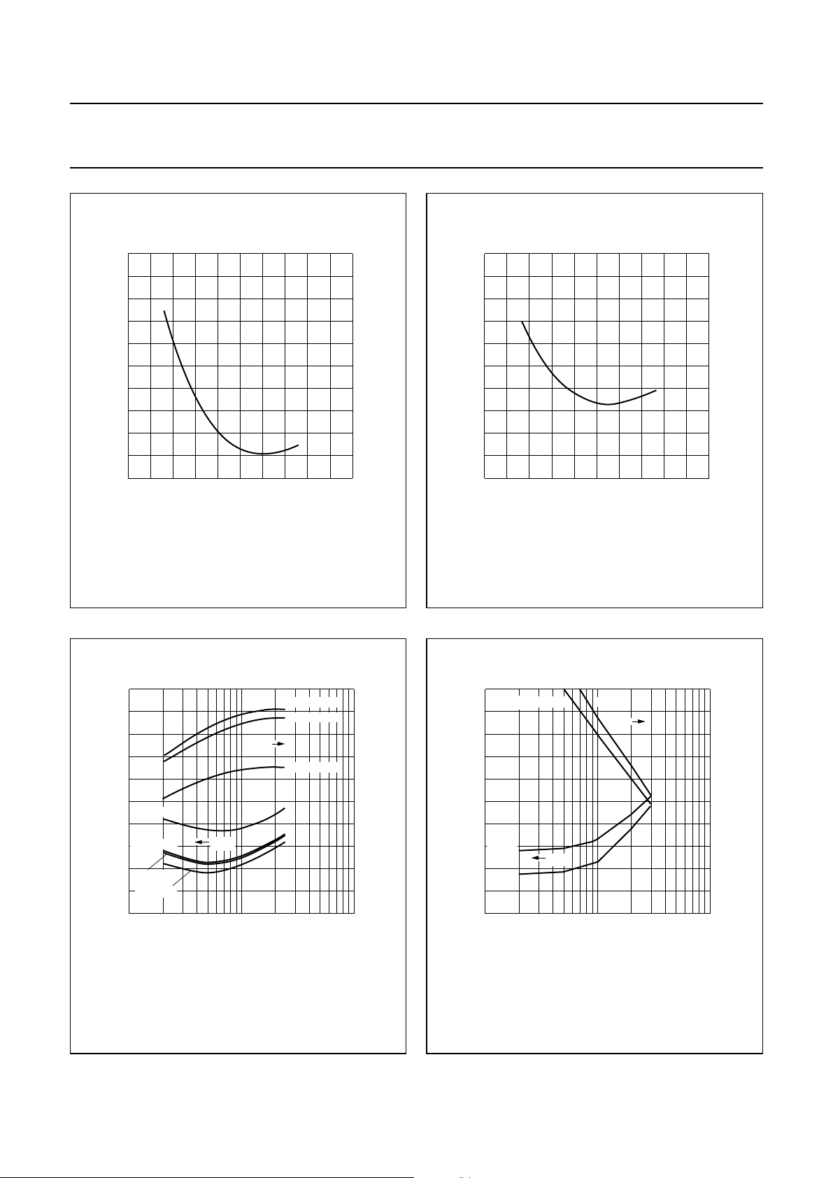
In Figs 7 to 10, GUM= maximum unilateral power gain;
MSG = maximum stable gain; G
gain.
= maximum available
max
25
handbook, halfpage
gain
(dB)
VCE= 6 V; f = 900 MHz; T
MSG
20
15
10
5
0
010
=25°C.
amb
20 30
Fig.7 Gain as a function of collector current.
MRA674
G
max
G
UM
I
(mA)
C
25
handbook, halfpage
gain
(dB)
20
15
MSG
10
5
0
010
VCE= 6 V; f = 2 GHz; T
amb
=25°C.
G
max
G
UM
20 30
Fig.8 Gain as a function of collector current.
MRA675
I
(mA)
C
50
handbook, halfpage
gain
G
(dB)
40
MSG
30
20
10
0
10
IC= 5 mA; VCE= 6 V; T
Fig.9 Gain as a function of frequency.
UM
10
amb
2
=25°C.
MRA676
G
max
3
10
f (MHz)
4
10
50
handbook, halfpage
gain
(dB)
40
30
20
10
0
10
IC= 20 mA; VCE= 6 V; T
10
amb
G
UM
MSG
2
=25°C.
3
10
G
max
f (MHz)
MRA677
4
10
Fig.10 Gain as a function of frequency.
Page 7
NXP Semiconductors Product specification
Rev. 04 - 23 November 2007
7 of 14
NPN 9 GHz wideband transistor BFG520; BFG520/X; BFG520/XR
40
MEA975
IC (mA)
−20
handbook, halfpage
d
im
(dB)
−30
−40
−50
−60
−70
050
10 20 30
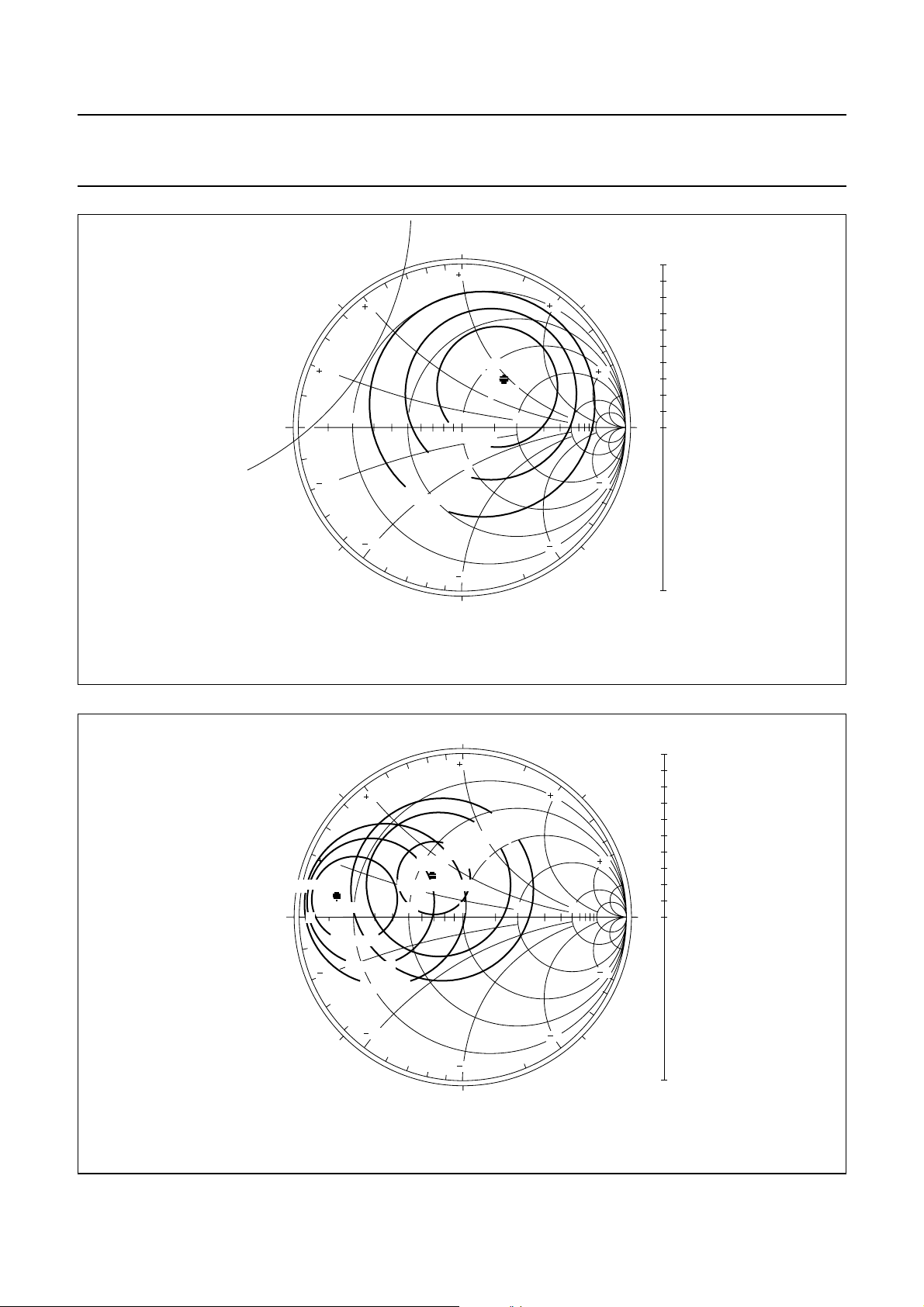
Fig.11 Intermodulation distortion as a function of
collector current.
40
MEA974
IC (mA)
−20
handbook, halfpage
d
2
(dB)
−30
−40
−50
−60
−70
050
10 20 30
Fig.12 Second order intermodulation distortion as
a function of collector current.
handbook, halfpage
5
F
min
(dB)
4
3
2000 MHz
2
1000 MHz
1
900 MHz
500 MHz
0
1
VCE= 6 V; T
amb
=25°C.
f = 900 MHz
1000 MHz
G
ass
2000 MHz
F
min
10
IC (mA)
Fig.13 Minimum noise figure and associated
available gain as functions of collector
current.
MRA682
20
G
ass
(dB)
15
10
5
0
−5
2
10
handbook, halfpage
5
F
min
(dB)
4
3
2
20 mA
1
5 mA
0
2
10
VCE= 6 V; T
amb
IC = 5 mA
=25°C.
20 mA
G
ass
F
min
3
10
f (MHz)
MRA683
20
G
ass
(dB)
15
10
5
0
−5
4
10
Fig.14 Minimum noise figure and associated
available gain as functions of frequency.
Page 8
NXP Semiconductors Product specification
Rev. 04 - 23 November 2007
8 of 14
NPN 9 GHz wideband transistor BFG520; BFG520/X; BFG520/XR
handbook, full pagewidth
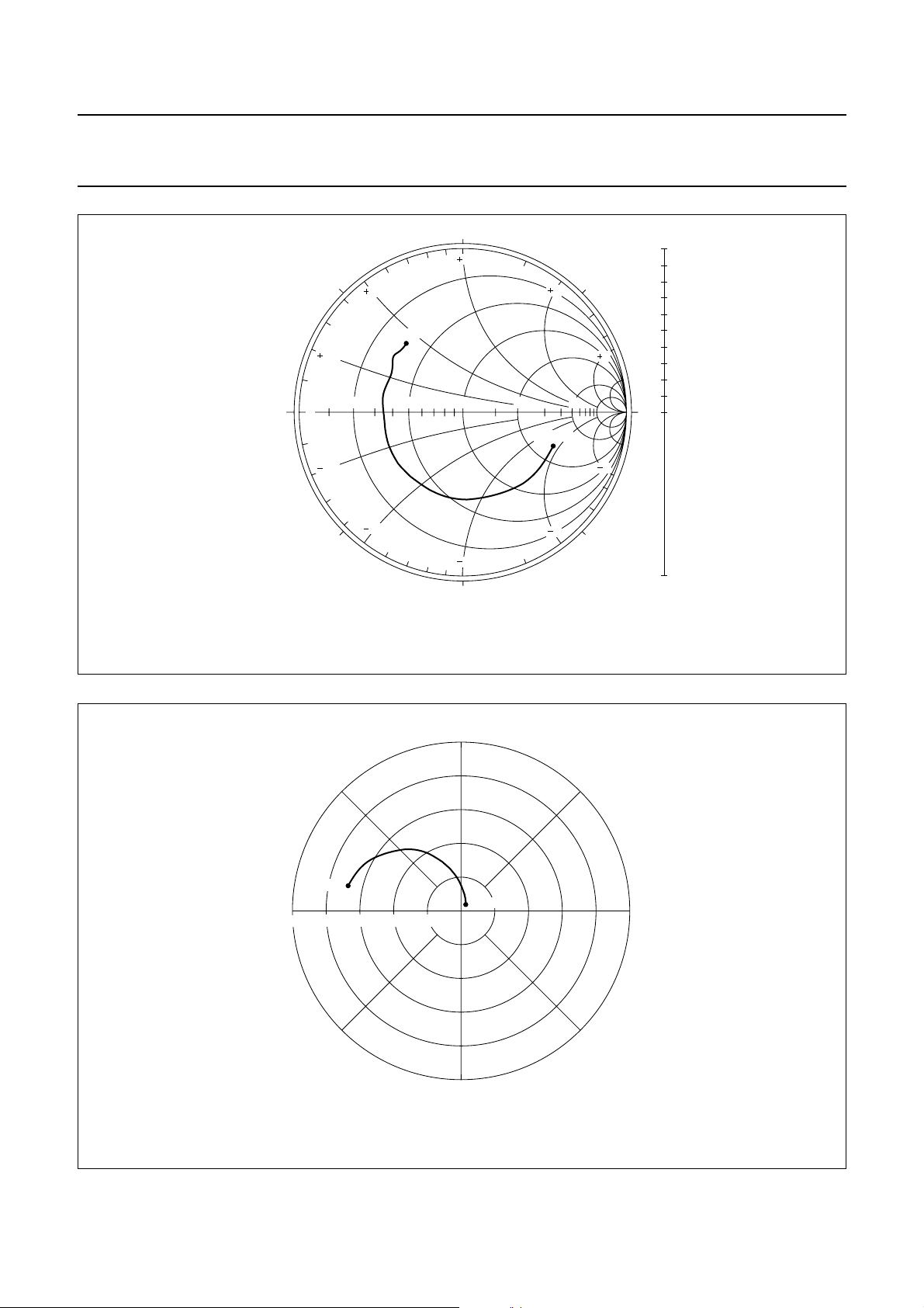
IC= 5 mA; VCE= 6 V;
f =900 MHz; Z
o
=50Ω.
pot. unst.
region
180°
stability
circle
135°
0
0.2
−135°
0.5
0.2
0.2 0.5 1 2 5
0.5
F = 2 dB
F = 3 dB
90°
1
F
min
F = 1.5 dB
1
−90°
Fig.15 Noise circle figure.
= 1. 1 dB
Γ
OPT
1.0
45°
2
5
5
2
−45°
MRA684
0.8
0.6
0.4
0.2
0°
0
1.0
handbook, full pagewidth
IC= 5 mA; VCE= 6 V;
f = 2 GHz; Z
=50Ω.
o
180°
G
max
135°
= 13 dB
Γ
0
0.2
−135°
0.5
0.2
0.2 0.5 1
MS
G = 12 dB
G = 11 dB
G = 10 dB
0.5
90°
1
F = 3 dB
F = 2.5 dB
F = 2 dB
Γ
OPT
F
= 1. 9 dB
min
2 5
1
−90°
Fig.16 Noise circle figure.
1.0
45°
2
5
5
2
−45°
MRA685
0.8
0.6
0.4
0.2
0°
0
1.0
Page 9
NXP Semiconductors Product specification
Rev. 04 - 23 November 2007
9 of 14
NPN 9 GHz wideband transistor BFG520; BFG520/X; BFG520/XR
handbook, full pagewidth
IC= 20 mA; VCE= 6 V.
Zo=50Ω.
90°
1
180°
135°
0
0.2
−135°
0.5
3 GHz
0.2
0.2 0.5 1 2 5
0.5
1
−90°
40 MHz
45°
2
2
−45°
Fig.17 Common emitter input reflection coefficient (S11).
5
5
MRA678
1.0
0.8
0.6
0.4
0.2
0°
0
1.0
handbook, full pagewidth
IC= 20 mA; VCE= 6 V.
90°
135°
45°
40 MHz
−90°
3 GHz
0°
−45°
MRA679
180°
50 40 30 20 10
−135°
Fig.18 Common emitter forward transmission coefficient (S21).
Page 10
NXP Semiconductors Product specification
Rev. 04 - 23 November 2007
10 of 14
NPN 9 GHz wideband transistor BFG520; BFG520/X; BFG520/XR
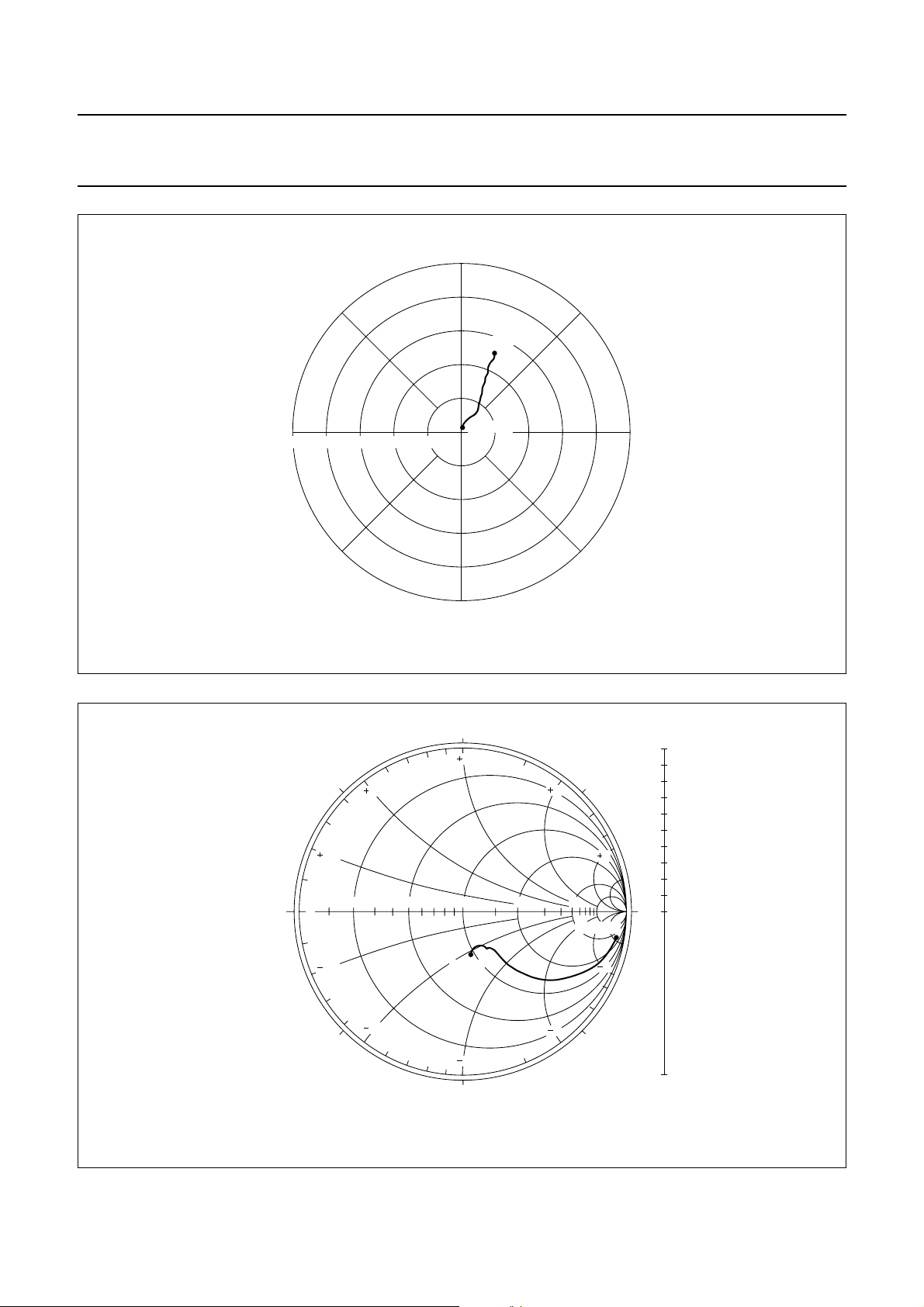
handbook, full pagewidth
IC= 20 mA; VCE= 6 V.
90°
135°
45°
3 GHz
180°
0.25 0.20 0.15 0.10 0.05
−135°
40 MHz
−45°
−90°
0°
MRA680
Fig.19 Common emitter reverse transmission coefficient (S12).
handbook, full pagewidth
IC= 20 mA; VCE= 6 V.
Zo=50Ω.
90°
1
180°
135°
0
0.5
0.2
0.2 0.5 1 2 5
45°
2
5
40 MHz
0.2
−135°
0.5
3 GHz
2
1
−90°
5
−45°
Fig.20 Common emitter output reflection coefficient (S22).
MRA681
1.0
0.8
0.6
0.4
0.2
0°
0
1.0
Page 11
NXP Semiconductors Product specification
Rev. 04 - 23 November 2007
11 of 14
NPN 9 GHz wideband transistor BFG520; BFG520/X; BFG520/XR
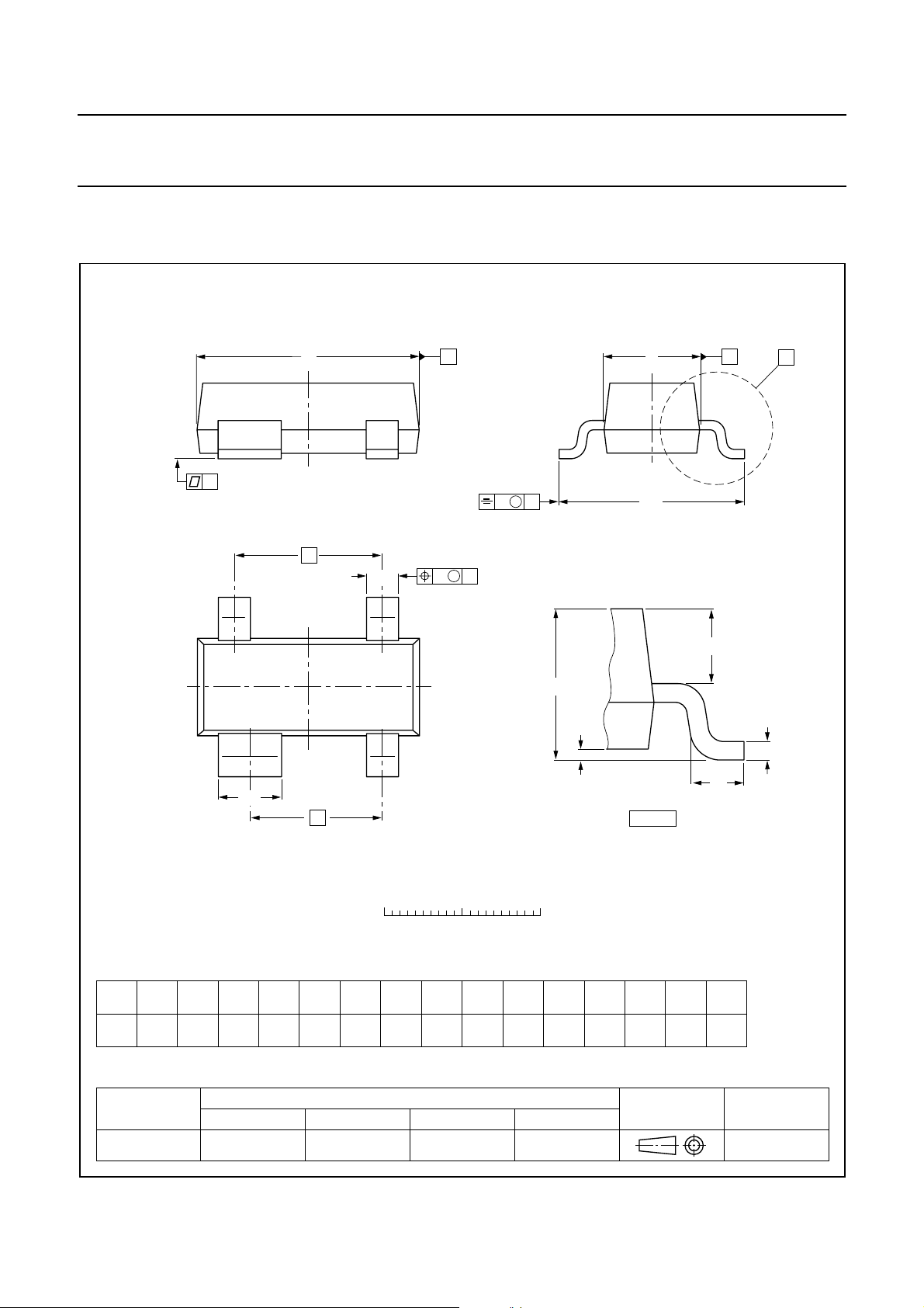
PACKAGE OUTLINES
Plastic surface mounted package; 4 leads SOT143B
D
y
e
b
p
B
w M
E
v M
A
B
H
E
A
X
34
Q
A
A
1
21
b
1
e
1
detail X
L
c
p
DIMENSIONS (mm are the original dimensions)
UNIT
mm
OUTLINE
VERSION
SOT143B
A
1.1
0.9
A
max
0.1
1
b
c
b
0.48
0.38
1
p
0.88
0.15
0.78
0.09
IEC JEDEC EIAJ
D
3.0
2.8
REFERENCES
0 1 2 mm
scale
1.4
1.2
E
e
1.9
e
1.7
H
E
1
2.5
2.1
L
0.45
0.15
p
0.55
0.45
EUROPEAN
PROJECTION
ywvQ
0.1 0.10.2
ISSUE DATE
97-02-28
Page 12
NXP Semiconductors Product specification
Rev. 04 - 23 November 2007
12 of 14
NPN 9 GHz wideband transistor BFG520; BFG520/X; BFG520/XR
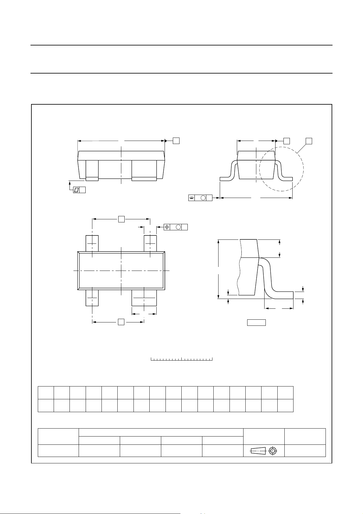
Plastic surface mounted package; reverse pinning; 4 leads SOT143R
D
y
e
b
p
B
w M
E
v M
A
B
H
E
A
X
43
Q
A
A
1
c
12
L
b
1
e
1
detail X
p
DIMENSIONS (mm are the original dimensions)
UNIT
mm
OUTLINE
VERSION
SOT143R
A
1.1
0.9
A
max
0.1
1
b
c
b
0.48
0.38
1
p
0.88
0.15
0.78
0.09
IEC JEDEC EIAJ
D
3.0
2.8
REFERENCES
0 1 2 mm
scale
1.4
1.2
E
e
1.9
e
1.7
H
E
1
2.5
2.1
L
0.55
0.25
p
0.45
0.25
EUROPEAN
PROJECTION
ywvQ
0.1 0.10.2
ISSUE DATE
97-03-10
Page 13

NXP Semiconductors
Rev. 04 - 23 November 2007
13 of 14
Legal information
Data sheet status
BFG520; BFG520/X; BFG520/XR
NPN 9 GHz wideband transistor
Document status
Objective [short] data sheet Development This document contains data from the objective specification for product development.
Preliminary [short] data sheet Qualification This document contains data from the preliminary specification.
Product [short] data sheet Production This document contains the product specification.
[1] Please consult the most recently issued document before initiating or completing a design.
[2] The term ‘short data sheet’ is explained in section “Definitions”.
[3] The product status of device(s) described in this documentmay have changed since this document was published and maydiffer in case of multiple devices. The latest product status
information is available on the Internet at URL
[1][2]
Product status
Definitions
Draft — The document is a draft version only. The content is still under
internal review and subject to formal approval, which may result in
modifications or additions. NXP Semiconductors does not give any
representations or warranties as to the accuracy or completeness of
information included herein and shall haveno liability for the consequencesof
use of such information.
Short data sheet — A short data sheet is an extract from a full data sheet
with the same product type number(s) and title. A short data sheet is intended
for quick reference only and should not be relied upon to contain detailed and
full information. For detailed and full information see the relevant full data
sheet, which is available on request via the local NXP Semiconductors sales
office. In case of any inconsistency or conflict with the short data sheet, the
full data sheet shall prevail.
Disclaimers
General — Information in this document is believed to be accurate and
reliable. However, NXP Semiconductors does not give anyrepresentations or
warranties, expressed or implied, as to the accuracyor completeness of such
information and shall have no liability for the consequences of use of such
information.
Right to make changes — NXP Semiconductors reserves the right to make
changes to information published in this document, including without
limitation specifications and product descriptions, at any time and without
notice. This document supersedes and replaces all information supplied prior
to the publication hereof.
Suitability for use — NXP Semiconductors products are not designed,
authorized or warranted to be suitable for use in medical, military, aircraft,
space or life support equipment, nor in applications where failure or
[3]
http://www.nxp.com.
Definition
malfunction of an NXP Semiconductors product can reasonably be expected
to result in personal injury, death or severe property or environmental
damage. NXP Semiconductors accepts no liability for inclusion and/or use of
NXP Semiconductors products in such equipment or applications and
therefore such inclusion and/or use is at the customer’s own risk.
Applications — Applications that are described herein for any of these
products are for illustrative purposes only. NXP Semiconductors makes no
representation or warranty that such applications will be suitable for the
specified use without further testing or modification.
Limiting values — Stress above one or more limiting values (as defined in
the Absolute Maximum Ratings System of IEC 60134) may causepermanent
damage to the device.Limiting valuesare stress ratings only andoperation of
the device at these or any other conditions above those given in the
Characteristics sections of this document is not implied. Exposure to limiting
values for extended periods may affect device reliability.
Terms and conditions of sale — NXP Semiconductors products are sold
subject to the general terms and conditions of commercial sale, as published
http://www.nxp.com/profile/terms, including those pertaining to warranty,
at
intellectual property rights infringement and limitation of liability, unless
explicitly otherwise agreed to in writing by NXP Semiconductors. In case of
any inconsistency or conflict between information in this document and such
terms and conditions, the latter will prevail.
No offer to sell or license — Nothing in this document may be interpreted
or construed as an offer to sell products that is open for acceptance or the
grant, conveyance or implication of any license under any copyrights, patents
or other industrial or intellectual property rights.
Trademarks
Notice: All referenced brands, product names, service names and trademarks
are the property of their respective owners.
Contact information
For additional information, please visit: http://www.nxp.com
For sales office addresses, send an email to: [email protected]
Page 14

NXP Semiconductors
BFG520; BFG520/X; BFG520/XR
NPN 9 GHz wideband transistor
Revision history
Revision history
Document ID Release date Data sheet status Change notice Supersedes
BFG520XR_N_4 20071123 Product data sheet - BFG520XR_CNV_3
Modifications:
BFG520XR_CNV_3 19950901 Product specification - BFG520XR_2
BFG520XR_2 - Product specification - BFG520XR_1
BFG520XR_1 - - - -
• Pinning table on page 2; changed code
Please be aware that important notices concerning this document and the product(s)
described herein, have been included in section ‘Legal information’.
© NXP B.V. 2007. All rights reserved.
For more information, please visit: http://www.nxp.com
For sales office addresses, please send an email to: [email protected]
Date of release: 23 November 2007
Document identifier: BFG520XR_N_4
 Loading...