

Philips BDP-9100 Service Manual

Service Manual
Service
Service
Blu-ray Disc Player
BDP 9100/12
1.1
3139 785 34881
Published by LO-YY 0921 AV System Printed in The Netherlands Subject to modification
Service
Service
Service
BDP5000/12 & BDP7300/12/51/93/98
©
Copyright 2009 Philips Consumer Electronics B.V. Eindhoven, The Netherlands
All rights reserved. No part of this publication may be reproduced, stored in a retrieval system or
transmitted, in any form or by any means, electronic, mechanical, photocopying, or otherwise
without the prior permission of Philips.
Published by LO-YY 0913 AV System Printed in The Netherlands Subject to modification
GB
Version 1.1
3139 785 34861

CONTENT
1 Technical Specifications and Connection Facilities
1-1 PCB Location 02
1-2 BDP-9100 Specification 03
2 Safety Information and General Notice
2-1 Safety Instructions 04
2-2 Laser Beam Safety Precautions 06
3 Quick Start Guide
3-1 Quick Start Guide 08
4 Mechanical Instructions
4-1 Dismantling Door of Driver (Loader) 11
4-2 Dismantling Front Panel 12
4-3 Dismantling Rear Panel 13
4-4 Dismantling Driver (Loader) 14
4-5 Dismantling Digital Board 15
4-6 Dismantling Analog Board 16
4-7 Dismantling PSU Board 17
Page
5 Firmware Upgrading Procedure
5-1 Upgrade Firmware of System and Loader 18
5-2 Service Diagnostics Process 24
6 Functional Test & Trouble Shooting Procedures
6-1 Flow Chart on How to Filter between Working and Defective Sets 26
6-2 Trouble Shooting 27
7 Block Diagram
7-1 Block diagram 31
7-2
7-3
7-4
7-5
7-6
8 Exploded View
8-1 BDP-9100 Exploded View 50
8-2 Packing Exploded View 51
9 Service Parts & Screws List
Front Board Diagrams
Digital Board Diagrams
Analog Board Diagrams
Standby Board Diagrams
PSU Board Diagrams
32
34
43
47
48
9-1 Parts & Screws List of BDP-9100 52
10 Revision List
10-1 Revision List 54
1

Technical Specifications & Connection Facilities
(
1. Technical Specifications and Connection Facilities
1-1.PCB Locations
Analog
Board
Digital
Board
PSU
Board
BD
DRIVER
(LOADER)
Standby Board
Behind the Front Cabinet)
Front Board
2
Rev. A

Technical Specifications & Connection Facilities
1-2 BDP 9100 Specifications
1-2-1 Playback Media
BD-Video,
DVD-Video,
DVD+/- R,
DVD +/- RW,
CD -R/CD-RW,
Audio CD, Video CD/SVCD,
Picture CD,
MP3 –CD,
MP3-DVD,
WMA-CD,
DivX (Ultra),
USB flash driver
1-2-2 Video
Signal system: PAL/NTSC
Composite video output: 1 Vp-p (75 ohm)
Component video output:
z Y: 1 Vp-p ( 75 ohm )
z Pb: 0.7 V-pp ( 75 ohm )
z Pr: 0.7 V-pp ( 75 ohm )
HDMI output:
480p/576p/720p/1080i/1080p
1-2-3 Audio
2 channel analogue output
z Audio Front L+R: 2Vrms (>1kohm)
5.1 channel analogue output
z Audio Front L+R: 2Vrms (>1kohm)
z Audio Surround L+R: 2Vrms
(>1kohm)
z Audio Center: 2Vrms (>1kohm)
z Audio Subwoofer: 1.15 Vrms
(>1kohm)
Digital output: 0.5 Vp-p (75 ohm )
z Optical / Coaxia
HDMI output:
Sampling Frequency:
z MP3 : 32 / 44.1 / 48 KHz
z WMA: 44.1 / 48 KHz
Constant bit rate:
z MP3 : 112 – 320 Kbps
z WMA: 48 – 192 Kbps
1-2-4 USB
Compatibility: Hi-Speed USB 2.0
Class Support:
z UMS (USB mass Storage Class)
z MTP (Media Transfer protocol)
1-2-5 Main Unit
Power supply rating: 110-240 V ~AC 50Hz
Power consumption: 30 W
Power consumption in standby mode:
0.2W
3
Rev. A
Safety Information & General Notice
2. Safety Information & General Notice
2-1 Safety Instructions
2-1-1 General Safety
Safety regulations are strongly required during repair action:
• Using isolation transformer to connect unit and mains.
• Replace safety components which have symbol
as same type as original one. Any other substitution component may cause risk of fire or electrical
short circuit issue.
Safety regulations are required after repair. You must return the unit back to original condition and
pay attention at the following points:
• Route the wires/cables correctly, and fix them with the mounted cable clamps.
• Check the insulation of the mains lead for external damage.
• Check the electrical DC resistance between the mains plug and the secondary side:
1. Unplug the mains cord, and connect a wire between the two pins of the mains plug.
2. To set the mains switch to the ‘on’ position (keep the mains cord unplugged!).
3. Measure the resistance value between the mains plug and the front panel, controls, and chassis
bottom.
4. Repair or correct unit when the resistance measurement is less than 1 M .Ω
5. Verify this, before you return the unit to the customer/user
6. Switch the unit ‘off’, and remove the wire between the two pins of the mains plug.
Laser Safety
The BD Driver is a laser device. Only allowed qualified service personnel to remove the cover and
repair action, because it might cause eye damage.
Laser Device Unit
Type : Semiconductor laser GaAlAs
Wavelength : 775-805 nm (CD)
: 640-663 nm (DVD)
: 400-410 nm (Blu-ray)
Output Power : 7 mW (CD)
: 7 mW (DVD)
: 20mW (Blu-ray)
Beam divergence : 60 degree
on it only allowed to change the component
REV. A
4

Safety Information & General Notice
2-1-2 Warnings
General
• All components which have been set on PCB board such as IC or Semiconductor are very
sensitive to static discharges (ESD
damage. Therefore, profession service man are not only to keep them at the same potential as the
mass of the set by a wristband with resistance but also have to keep components and tools at this
same potential while assembling or disassembling parts.
• Be careful during measurements in the live voltage section. The primary side of the power supply,
including the heats ink, carries live mains voltage when you connect the player to the mains (even
when the player is ‘off’!). It is possible to touch copper tracks and/or components in this unshielded
primary area, when you service the player. Service personnel must take precautions to prevent
touching this area or components in this area. A ‘lightning stroke’ and a stripe-marked printing on
the printed wiring board, indicate the primary side of the power supply.
• Never replace modules or components, while the unit is set at ‘on’ position.
Laser
• The laser products which been used at BD Player driver will cause eyes damage.
• Only qualified service engineer can remove the cover of laser product and maintain this device.
• Repair handling should put a disc inside the player.
). Careless handling during repair can cause component
REV. C
5

Safety Information & General Notice
2-2 LASER BEAM SAFETY PRECAUTIONS
This BD player uses a pickup which will emits laser beam.
Do not look laser beam which
comes from pickup directly
The laser beam will be emitted from pickup as shown above figure. Please be sure, there are more
then 30 cm away between your eyes and pickup lens, while laser equipment is turned on. Do not
look laser beam directly.
CAUTION: Use of controls and adjustments, or doing procedures other than those specified here in,
may result in hazardous radiation exposure.
REV. A
6
Safety Information & General Notice
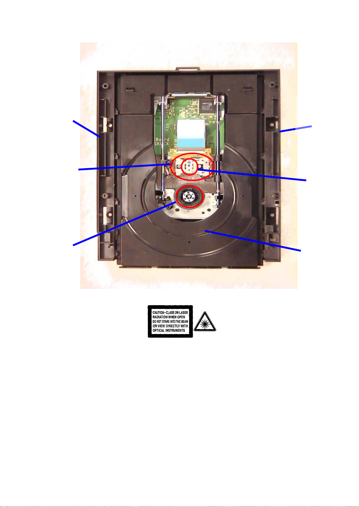
Driver
Mechanism
Assy.
Laser
Pickup
Turntable
Driver
Mechanism
Assy.
Laser Beam
Radiation
Tray Dish
Mechanism of BD Driver
REV. C
7

Quick Start Guide
8
3. QUICK START GUIDE
3-1 Quick Start Guide
The following excerpt of the Quick Start Guide serves as an introduction to the set.
The complete Direction for Use can be downloaded in different languages from the internet
site of Philips Consumer Care Center: www.p4c.philips.com
9

Quick Start Guide
9
BDP9100
10

Quick Start Guide
1
10
11

Mechanical Instructions
4 .Mechanical Instructions
4-1 Dismantling Door of Driver Loader
1) Up-side-down BD Player
2) Insert a stick into the slot which has been created at the bottom and moving the
stick to reverse direction to unlock loader’s tray. See figure 4-1-1
(Bottom of BD Player)
Action 1
Action 2
Action 3
Figure 4-1-1: Unlock Tray of Loader
3) Pull out the tray of Loader and remove the door on the up direction.
See figure 4-1-2
Figure 4-1-2: Removing Door
REV. A
11

Mechanical Instructions
4-2 Dismantling Front panel
1) Firstly remove DVD door. ( see Figure 4-1-1 &4-1-2)
2) Unlock 6 top cover screws and then remove Top cover
3) Finally, remove 7 hooks (See Figure 4-2-1 & Figure 4-2-2)
6 screws of
top cover
( Hooks )
(Top cover direction)
(Door out direction)
3
Figure 4-2-1
(Hooks)
Figure 4-2-2
REV. A
12

Mechanical Instructions
4-3 Dismantling Rear panel
1) Remove top cover (see Figure 4-2-1)
2) For BDP7300, Remove 9 screws of rear panel. (Figure 4-3-1)
9 screws of rear panel
Figure 4-3-1 Rear panel of BDP 7300
3) For BDP5000, Remove 7 screws of rear panel. (Figure 4-3-1)
7 screws of rear panel
Figure 4-3-2 Rear panel of BDP 5000
REV. A
13

Mechanical Instructions
4-4 Dismantling DRIVER (LOADER)
1) Remove Door. (See Figure 4-1-1)
2) Remove Cover. ( See Figure 4-2-1)
3) Unscrew 4 screws and 2 cables. (See Figure 4-4-1 )
4) Remove Driver
4 screws of
BD Player
PSU connector
Figure 4-4-1 Remove Driver
Digital board connector
REV. A
14
Mechanical Instructions
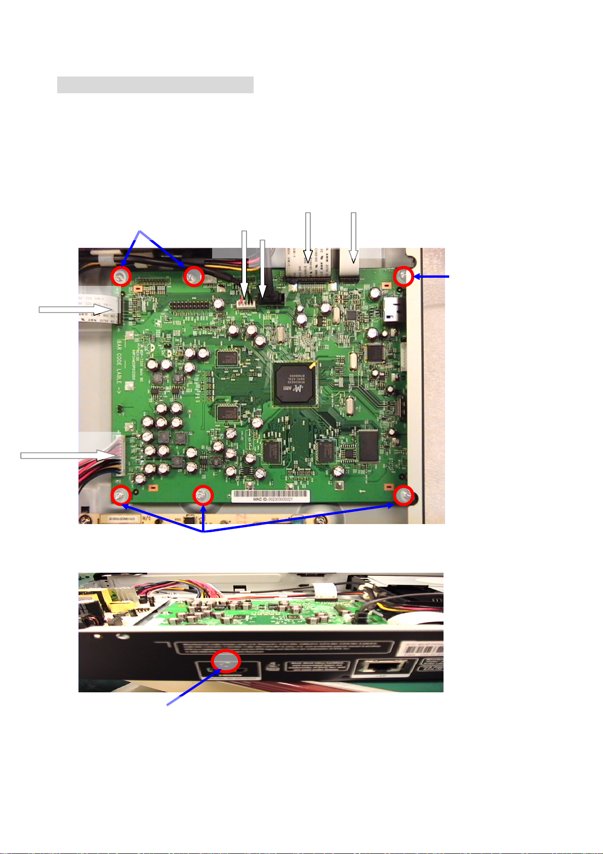
4-5 Dismantling Digital board
1) Detach 3 FFC Cables and 3 connecters. (See Figure 4-5-1)
2) Unscrew 6 screws of Digital Board
3) Remove HDMI screw at Real panel. (See Figure 4-5-2 )
Screw 1 & 2
PSU connector
Driver connector
FFC cable 1
FFC cable 3
PSU connector
FFC cable 2
Screw 3
Screw 4, 5, 6
Figure 4-5-1 Digital board
HDMI Screw
Figure 4-5-2
REV. A
15
Mechanical Instructions
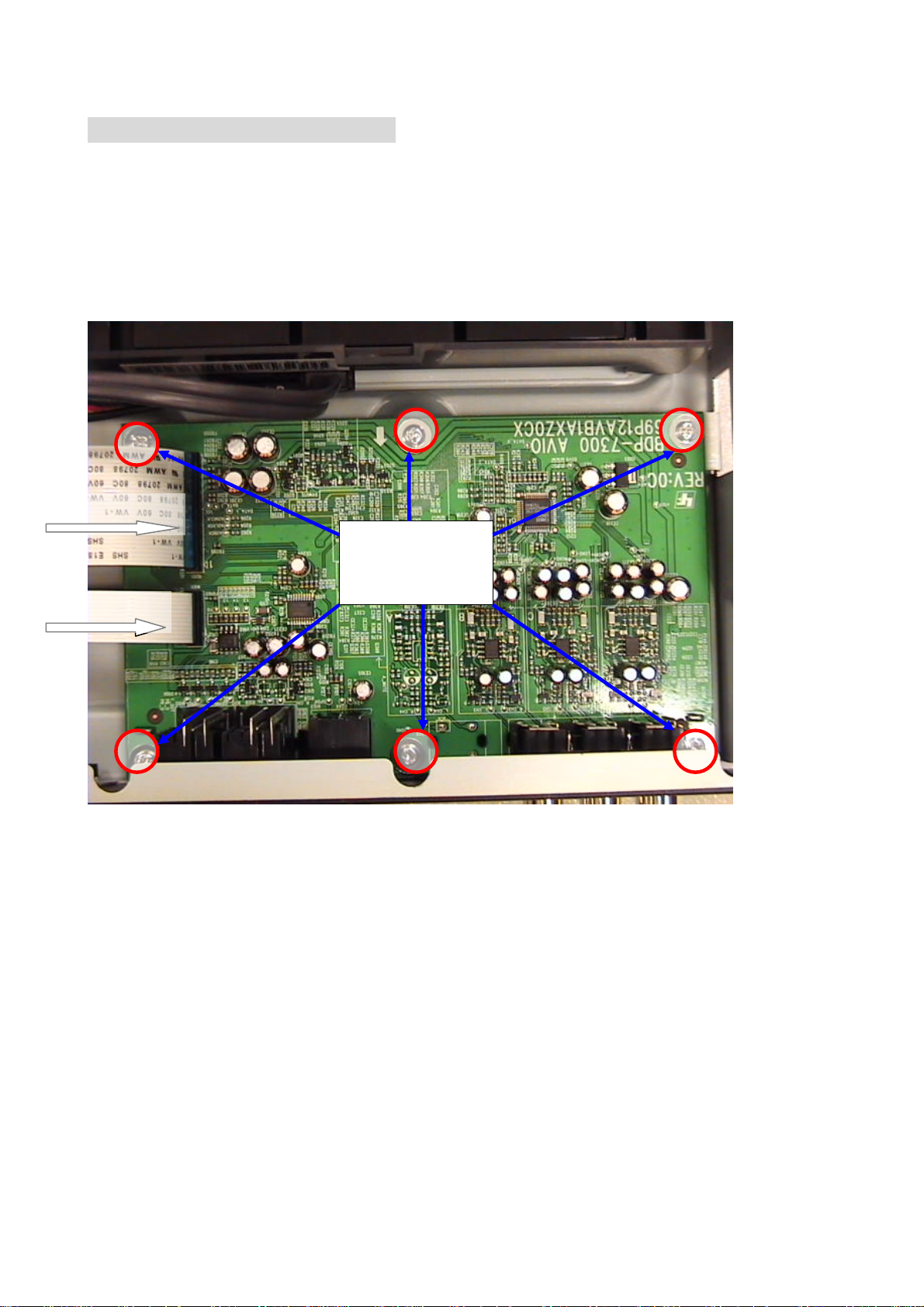
4-6 Dismantling Analog board
1) Remove 2 FFC cables and unscrew 6 screws on Analog board. (See figure 4-6-1)
2) Remove Real panel :
2-1) For BDP-7300 (See Figure 4-3-1)
2-2) For BDP-5000 (See Figure 4-3-2)
FFC cable 1
FFC cable 2
6 screws of
Analog Board
Figure 4-6-1 Analog board
REV. A
16
 Loading...