

Philips BA591 Datasheet
DISCRETE SEMICONDUCTORS
DATA SH EET
ook, halfpage
M3D049
BA591
Band-switching diode
Product specification
Supersedes data of 1998 Aug 18
1998 Aug 31

Philips Semiconductors Product specification
Band-switching diode BA591
FEATURES
• Very small plastic SMD package
• Low diode capacitance:
max. 1.05 pF
• Low diode forward resistance:
DESCRIPTION
The BA591 is a planar, high
performance band-switching diode in
the very small SOD323 SMD plastic
package.
PINNING
PIN DESCRIPTION
1 cathode
2 anode
max. 0.7 Ω
• Small inductance.
handbook, halfpage
12
APPLICATIONS
• Low loss band-switching in VHF
television tuners
• Surface mount band-switching
circuits.
Marking code: A1.
The marking band indicates the cathode.
MAM406
Fig.1 Simplified outline (SOD323) and symbol.
LIMITING VALUES
In accordance with the Absolute Maximum Rating System (IEC 134).
SYMBOL PARAMETER CONDITIONS MIN. MAX. UNIT
V
R
I
F
P
tot
T
stg
T
j
continuous reverse voltage − 35 V
continuous forward current − 100 mA
total power dissipation Ts=90°C − 500 mW
storage temperature −65 +150 °C
junction temperature −65 +150 °C
ELECTRICAL CHARACTERISTICS
= 25°C unless otherwise specified.
T
j
SYMBOL PARAMETER CONDITIONS TYP. MAX. UNIT
V
F
I
R
C
d
r
D
1/g
p
L
S
forward voltage IF=10mA − 1V
reverse current VR=20V − 20 nA
diode capacitance f = 1 MHz; note 1; see Fig.2
V
= 1 V 0.8 1.05 pF
R
V
= 3 V 0.65 0.9 pF
R
diode forward resistance f = 100 MHz; note 1; see Fig.3
I
= 3 mA 0.45 0.7 Ω
F
I
= 10 mA 0.36 0.5 Ω
F
reverse resistance VR= 1 V; f = 100 MHz; note 1 100 − kΩ
series inductance 2 − nH
Note
1. Guaranteed on AQL basis; inspection level S4, AQL 1.0.
1998 Aug 31 2
Philips Semiconductors Product specification
Band-switching diode BA591
THERMAL CHARACTERISTICS
SYMBOL PARAMETER VALUE UNIT
R
th j-s
GRAPHICAL DATA
thermal resistance from junction to soldering point 120 K/W
1.6
handbook, halfpage
C
d
(pF)
1.2
0.8
0.4
0
01020
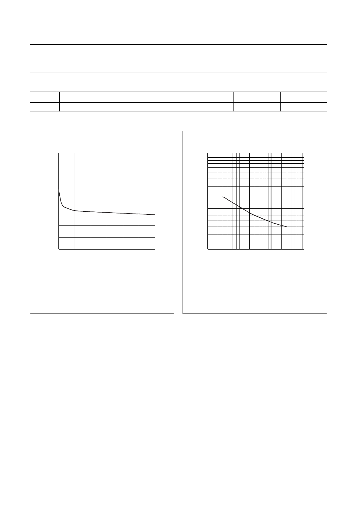
f =1 MHz; Tj=25°C.
MGL477
V
30
(V)
R
Fig.2 Diode capacitance as a function of reverse
voltage; typical values.
10
handbook, halfpage
r
D
(Ω)
1
−1
10
−1
10
f = 100 MHz; Tj=25°C.
110
MGL476
I
(mA)
F
Fig.3 Diode forward resistance as a function of
forward current; typical values.
2
10
1998 Aug 31 3
 Loading...